

Page 1

PN 4329967 (English) May 2013, Rev. 1 12/2013
2013 Fluke Corporation.
All product names are trademarks of their respective companies.
*4329967*
DSX
CableAnalyzer
™
Getting Started Guide
The DSX-5000 CableAnalyzer modules attach to Versiv™ main
and remote units to make rugged, hand-held testers that let you
certify, troubleshoot, and document twisted pair network
cabling.
Accessing the Product Manuals
This guide provides basic information to help you get started
using the tester. For more detailed information, see the latest
versions of the DSX CableAnalyzer Users Manual and the Versiv
Technical Reference Handbook provided on the Product
Manuals DVD and on the Fluke Networks website.
Safety Information
Warning
To prevent possible fire, electric shock, or personal injury:
Read all safety information before you use the
Product.
Carefully read all instructions.
Warning or Caution: Risk of damage or destruction to
equipment or software. See explanations in the
manuals.
Warning: Risk of fire, electric shock, or personal
injury.
This key turns the Product on and off.
Page 2

Do not connect the tester to telephony inputs,
systems, or equipment, including ISDN inputs.
Doing so is a misapplication of this product, which
could result in damage to the tester and create a
potential shock hazard to the user.
Do not open the case. You cannot repair or replace
parts in the case.
Do not modify the Product.
Use only replacement parts that are approved by
Fluke Networks.
Do not touch voltages > 30 V AC rms, 42 V AC peak,
or 60 V AC.
Do not use the Product around explosive gas, vapor,
or in damp or wet environments.
Use this Product indoors only.
Do not connect the Product to voltages that are
higher than the maximum voltage rating for the
Product.
For Products that have multiple connectors for
different types of tests on copper cabling,
disconnect unused test leads from the connectors
before you do a test.
Use the Product only as specified, or the protection
supplied by the Product can be compromised.
Do not use and disable the Product if it is damaged.
Do not use the Product if it operates incorrectly.
Batteries contain hazardous chemicals that can
cause burns or explode. If exposure to chemicals
occurs, clean with water and get medical aid.
Remove the batteries if the Product is not used for
an extended period of time, or if stored in
temperatures above 50 °C. If the batteries are not
removed, battery leakage can damage the Product.
The battery door must be closed and locked before
you operate the Product.
Repair the Product before use if the battery leaks.
Recharge the batteries when the low battery
indicator shows to prevent incorrect measurements.
Turn off the Product and disconnect all test leads,
patch cords, and cables before you replace the
battery.
Page 3
Do not disassemble or crush battery cells and
battery packs.
Do not put battery cells and battery packs near heat
or fire. Do not put in sunlight.
Do not operate the Product with covers removed or
the case open. Hazardous voltage exposure is
possible.
Remove the input signals before you clean the
Product.
Have an approved technician repair the Product.
Do not put metal objects into connectors.
For Products with rechargeable batteries, use only
AC adapters approved by Fluke Networks for use
with the Product to supply power to the Product
and charge the battery.
Caution
To prevent damage to the Product or cables under test
and to prevent data loss, read all safety information given
in all documentation supplied with the Product.
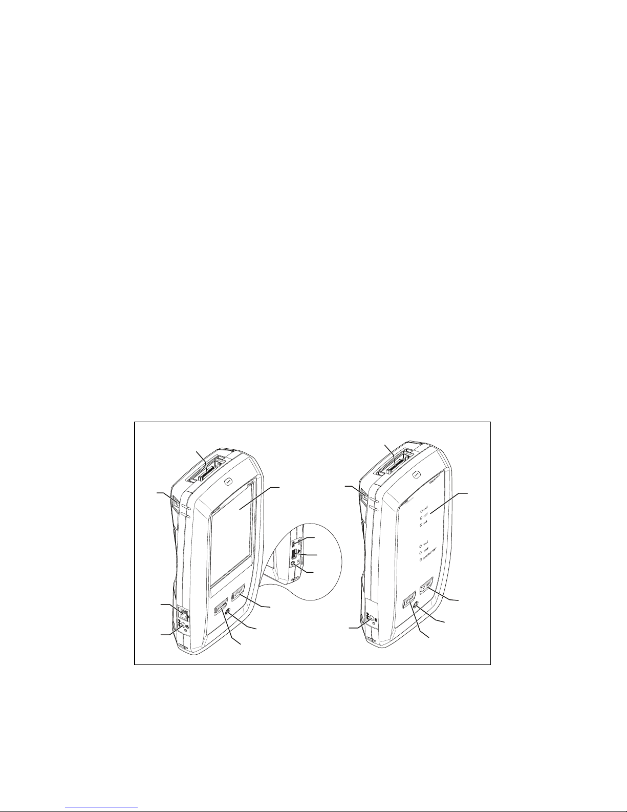
Connectors, Keys, and LEDs
HFO00EPS
Figure 1. Connectors, Keys, and LEDs
Connector for a link interface adapter.
RJ45 jack for communications between the main and remote
testers when you do alien crosstalk measurements.
LCD display with touchscreen.
A
B
H
G
C
I
K
J
D
E
F
A
B
G
L
D
E
M
Page 4

: Starts a test. To start a test, you can also tap TEST on the
display.
Power key.
: Press to go to the home screen.
Connector for the ac adapter. The LED is red when the battery
charges, and green when the battery is fully charged. The LED
is yellow if the battery will not charge.
RJ45 connector: For functions available in future software
releases.
Micro-AB USB port: This USB port lets you connect the tester to
a PC so you can upload test results to the PC and install
software updates in the tester.
Type A USB port: This USB host port lets you save test results on
a USB flash drive or connect a video probe to the tester.
Headset jack.
PASS LED comes on when a test passes.
TEST LED comes on during a test.
FAIL LED comes on when a test fails.
TALK LED comes on when the talk function is on (see ). To
adjust the volume, press
or the button on the headset’s
microphone.
TONE LED flashes and the toner comes on when you press
and a main tester is not connected to the remote.
LOW BATTERY LED comes on when the battery is low.
Note
The LEDs also operate as a battery gauge when
you turn on the remote. See the Users Manual.
: Press to use the headset to speak to the person
at the other end of the link. Press again to adjust the volume.
To turn off the talk function, hold down
.
How to Certify Twisted Pair Cabling
1.
Power the Tester
Charge the battery if necessary. Connect the ac adapter to
ac power and to the adapter connector () shown in Figure
1. You can use the tester while the battery charges.
2.
Select Settings
2-1
On the home screen, tap the test setup panel (see
Figure 2).
2-2
On the CHANGE TEST screen, tap a twisted pair test, then
tap EDIT.
Page 5

2-3
On the TEST SETUP screen, tap the panels to change
settings:
Cable Type: Select a cable type that is correct for the
type you will test.
Test Limit: Select the correct test limit for the job. To see a
different group of limits, tap MORE, then tap the name of
a group.
2-4
Outlet Configuration: Select the correct configuration for
the cable you will test.
2-5
To save the settings, tap SAVE on the TEST SETUP screen.
-continued-
Figure 2. Panels on the Home Screen
HFO01.EPS
To set up a project, tap the PROJECT panel.
To change settings for the test or select a different test, tap
the test setup panel.
To set up cable IDs and turn on Auto Save, tap the Next ID
panel.
To enter the operator name, tap the Operator panel.
A
B
C
D
Page 6

3.
Make Connections and Do a Test
3-1
Connect the testers to the link as shown in Figure 3 or 4.
3-2
Tap TEST on the main tester or press on the main
or remote tester.
GPU97.EPS
Figure 3. Permanent Link Connections
GPU96.EPS
Figure 4. Channel Connections
Patch
panel
Start permanent
link
End permanent
link
Horizontal cabling
Tester with
permanent link
adapter
Remote with
permanent link
adapter
Wall outlet
Optional
consolidation
point
Patch cord
from hub or
switch
Start channel End channel
Horizontal cabling
Tester with
channel adapter
Remote with
channel adapter
Wall outlet
Optional
consolidation
point
Hub or switch
Patch cord
from PC
Page 7

4.
Examine the Results
The tester shows multiple views of the test results (Figure 5):
WIRE MAP: Shows the connections between the ends of
the cable under test. The tester compares the connections
to the selected Outlet Configuration to get a PASS or FAIL
result.
PERFORMANCE: Shows the overall result for each test that
is required by the selected test limit. To see detailed results
for a test, tap the panel.
DIAGNOSTIC: Shows the HDTDR™ and HDTDX™ analyzer
results, which help you troubleshoot failures.
HFO02.EPS
Figure 5. Examples of Twisted Pair Results Screens
5.
Save the Results
5-1
Tap SAVE if the test passed or FIX LATER if the test
failed.
5-2
If the Cable ID box shows the correct ID, tap SAVE.
To enter a cable ID, tap the Cable ID box on the SAVE RESULT
screen, use the keyboard to enter a name for the results, tap
DONE, then tap SAVE.
The tester saves the results in the DEFAULT project, unless you
selected a different project.
About Projects
You can set up a project to specify the settings and tests
necessary for a job, monitor the status of a job, and organize the
test results.
To start a new project, tap PROJECT on the home screen, tap
CHANGE PROJECT, then tap NEW PROJECT. See the Users Manual
or Technical Reference Handbook on the DVD for more
information.
Page 8

About the AxTalk Analyzer Kit
The DSX-5000 kit includes the hardware and AxTalk Analyzer
software you need to do tests for alien crosstalk on twisted pair
cabling. Alien crosstalk is noise, or crosstalk, transmitted
between adjacent cables in a bundle or patch panel. Alien
crosstalk is a primary source of noise in cabling used for
10GBASE-T applications.
For instructions on how to do alien crosstalk tests, install the
AxTalk Analyzer software supplied on the Versiv/AxTalk
Analyzer DVD, then see the online help in the software.
Registration
Registering your product with Fluke Networks gives you access
to valuable information on product updates, troubleshooting
tips, and other support services.
To register, use LinkWare software.
Contact Fluke Networks
www.flukenetworks.com
support@flukenetworks.com
1-800-283-5853, +1-425-446-5500
Fluke Networks operates in more than 50 countries worldwide.
For more contact information, go to our website.
General Specifications
Battery Type Lithium-ion
Te mp er at ur e Operating: 0 °C to +45 °C
Storage: -30 °C to +60 °C
Altitude Operating: 4,000 m (3,200 m with AC
adapter)
Storage: 12,000 m
Page 9

Certifications and Compliance
Conformite Europeene. Conforms to the
requirements of the European Union and the
European Free Trade Association (EFTA).
Listed by the Canadian Standards Association.
Conforms to relevant Australian standards.
Conforms to relevant Russian standards.
KCC-REM-FKN-012001001: EMC approval for Korea
Class A Equipment (Industrial Broadcasting &
Communication Equipment)
This product meets requirements for industrial (Class
A) electromagnetic wave equipment and the seller or
user should take notice of it. This equipment is
intended for use in business environments and is not
to be used in homes.
A 급 기기 ( 업무용 방송통신기자재 )
이 기기는 업무용 (A 급 ) 전자파적합기기로서 판매자 또
는 사용자는 이 점을 주의하시기 바라며 , 가정외의 지역
에서 사용하는 것을 목적으로합니다 .
Page 10

LIMITED WARRANTY AND LIMITATION OF LIABILITY
Fluke Networks mainframe products will be free from defects in
material and workmanship for one year from the date of purchase.
Parts, accessories, product repairs and services are warranted for 90
days, unless otherwise stated. Ni-Cad, Ni-MH and Li-Ion batteries,
cables or other peripherals are all considered parts or accessories.
This warranty does not cover damage from accident, neglect, misuse,
alteration, contamination, or abnormal conditions of operation or
handling. Resellers are not authorized to extend any other warranty
on Fluke Networks’ behalf. To obtain service during the warranty
period, contact your nearest Fluke Networks authorized service
center to obtain return authorization information, then send your
defective product to that Service Center with a description of the
problem.
THIS WARRANTY IS YOUR ONLY REMEDY. NO OTHER WARRANTIES,
SUCH AS FITNESS FOR A PARTICULAR PURPOSE, ARE EXPRESSED OR
IMPLIED. FLUKE NETWORKS IS NOT LIABLE FOR ANY SPECIAL,
INDIRECT, INCIDENTAL OR CONSEQUENTIAL DAMAGES OR LOSSES,
ARISING FROM ANY CAUSE OR THEORY.
Since some states or countries do not allow the exclusion or
limitation of an implied warranty or of incidental or consequential
damages, this limitation of liability may not apply to you.
Fluke Networks
PO Box 777
Everett, WA 98206-0777
USA
4/04
 Loading...