

Page 1

AMH-38™/AMH-100™
Automated Mass Handling System
for PG7000 Piston Gauges
Operation and Maintenance Manual
© 2007 DH Instruments, a Fluke Company
Page 2

© 2007, DH Instruments, a Fluke Company All rights reserved.
Information in this document is subject to change without notice. No part of this document may be reproduced or transmitted in any
form or by any means, electronic or mechanical, for any purpose, without the express written permission of DH Instruments, a
Fluke Company 4765 East Beautiful Lane Phoenix AZ 85044-5318 USA.
DH Instruments makes every effort to ensure the accuracy and quality of its published materials; however, no warranty, expressed
or implied, is provided. DH Instruments disclaims any responsibility or liability for any direct or indirect damages resulting from the
use of the information in this manual or products described in it. Mention of any product or brand does not constitute an
endorsement by DH Instruments of that product or brand. This manual was originally composed in English and was subsequently
translated into other languages. The fidelity of subsequent translations cannot be guaranteed. In case of conflict between the
English version and another language version, the English version takes precedence.
DH Instruments, DH, DHI, AMH-38, AMH-100, PG7000, PG7xxx are trademarks of DH Instruments, a Fluke Company, registered
and otherwise.
Krytox is a registered trademark of the Dupont de Nemours Company.
Pyrex is a registered trademark of Dow Corning.
Document No. 550133-02
040726
Printed in the USA.
© 2007 DH Instruments, a Fluke Company
Page 3

TABLE OF CONTENTS
T
AABBLLEE
T
O
O
FF
C
OONNTTEENNTTS
C
S
TABLE OF CONTENTS ...............................................................I
TABLES.................................................................................III
FIGURES................................................................................III
ABOUT THIS MANUAL..............................................................V
1. INTRODUCTION ................................................................. 1
1.1 PRODUCT OVERVIEW ...........................................................................................................................1
1.2 LOCATION AND DESCRIPTION OF THE COMPONENTS....................................................................2
1.2.1 AMH-38..........................................................................................................................................................2
1.2.2 AMH-100........................................................................................................................................................3
1.3 SPECIFICATIONS ...................................................................................................................................4
2. PREPARATION FOR OPERATION ......................................... 5
2.1 UNPACKING AND INSPECTION ............................................................................................................5
2.2 SITE REQUIREMENTS............................................................................................................................7
2.2.1 SITE................................................................................................................................................................7
2.2.2 GAS SUPPLIES.............................................................................................................................................7
2.2.2.1 DRIVE AIR SUPPLY ..................................................................................................................................7
2.2.2.2 VACUUM SUPPLY (AMH-38 ONLY) .........................................................................................................8
2.3 SETTING UP THE AMH FOR OPERATION............................................................................................8
2.3.1 GENERAL CONSIDERATIONS.....................................................................................................................9
2.3.2 SETTING UP THE AMH.................................................................................................................................9
2.3.2.1 CONNECTING THE DRIVE AIR SUPPLY.................................................................................................9
2.3.2.2 CONNECTING THE DRIVE VACUUM SUPPLY (AMH-38 ONLY)..........................................................11
2.3.2.3 CONNECTING ELECTRICAL POWER....................................................................................................11
2.3.2.4 CONNECTING PG7000 PLATFORM COMMUNICATIONS....................................................................12
2.3.2.5 CONNECTING A REFERENCE VACUUM SUPPLY (AMH-38 ONLY)....................................................12
2.3.2.6 CONNECTING AN EXTERNAL REFERENCE VACUUM GAUGE (AMH-38 ONLY)..............................13
2.4 PREPARING THE PG7000 PLATFORM...............................................................................................13
2.4.1 PREPARING PG7102, PG7202, PG7302 PLATFORM HARDWARE FOR AMH-100................................13
2.4.2 PREPARING PG7601 PLATFORM HARDWARE FOR AMH-38................................................................13
2.4.3 VERIFYING PG7000 EMBEDDED SOFTWARE VERSION FOR AMH SUPPORT....................................14
2.5 CHECKING THE PG7000 PISTON-CYLINDER MODULES FOR AMH OPERATION..........................14
2.5.1 CHECKING THE PISTON CAP...................................................................................................................14
2.5.2 CHECKING THE PISTON STOP BUSHING ..............................................................................................15
2.6 INSTALLING THE AMH MASS SET......................................................................................................15
2.7 INITIAL START UP/VERIFICATION......................................................................................................17
3. OPERATION..................................................................... 19
3.1 GENERAL OPERATING PRINCIPLES .................................................................................................19
3.2 OPERATION..........................................................................................................................................22
3.2.1 INSTALLING THE AMH MASS HANDLER ON THE PG7000 PLATFORM ...............................................22
3.2.1.1 INSTALLING AMH-38 ..............................................................................................................................23
3.2.1.2 INSTALLING AMH-100 ............................................................................................................................24
3.2.2 REMOVING THE AMH MASS HANDLER FROM THE PG7000 PLATFORM............................................25
3.2.2.1 REMOVING AMH-38................................................................................................................................25
3.2.2.2 REMOVING AMH-100..............................................................................................................................25
3.2.3 REGULAR MASS TO PRESSURE OR PRESSURE TO MASS OPERATION...........................................26
3.2.4 DIRECT CONTROL OF AMH FUNCTIONS ................................................................................................26
Page I © 2007 DH Instruments, a Fluke Company
Page 4

AMH-38™ AND AMH-100™ OPERATION AND MAINTENANCE MANUAL
3.2.5 MAKING AND BREAKING THE REFERENCE VACUUM (AMH-38 ONLY)...............................................27
3.2.6 ACCESSING THE PG7000 PISTON-CYLINDER MODULE .......................................................................27
3.2.7 INDICATOR LED..........................................................................................................................................27
3.2.8 ERROR MESSAGES...................................................................................................................................28
4. REMOTE OPERATION ....................................................... 31
4.1 OVERVIEW............................................................................................................................................31
5. MAINTENANCE AND ADJUSTMENTS .................................. 33
5.1 MAINTENANCE.....................................................................................................................................33
6. TROUBLESHOOTING ........................................................ 35
7. WARRANTY STATEMENT .................................................. 37
7.1 WARRANTY STATEMENT....................................................................................................................37
© 2007 DH Instruments, a Fluke Company Page II
Page 5

TABLES AND FIGURES
T
AABBLLEES
T
Table 1. AHM-38 Parts List..........................................................................................................................5
Table 2. AHM-100 Parts List........................................................................................................................6
Table 3. Drive Air Pressure Requirement by Mass Set...............................................................................7
Table 4. AMH Errors ..................................................................................................................................28
Table 5. AMH Troubleshooting Checklist ..................................................................................................35
Table 6. DHI Authorized Service Providers...............................................................................................37
F
IIGGUURREES
F
Figure 1. AMH-38 Automated Mass Handler...............................................................................................2
Figure 2. AMH-100 Automated Mass Handler.............................................................................................3
Figure 3. PG7601 Vacuum Plate Detail.....................................................................................................13
Figure 4. Piston Cap Inspection.................................................................................................................15
Figure 5. Piston Cap/Bell Testing ..............................................................................................................15
Figure 6. Piston-Cylinder Module Piston Stop Bushing............................................................................15
Figure 7. AMH Mass Set............................................................................................................................16
Figure 8. AMH Schematic/Operating Principle..........................................................................................21
Figure 9. AMH Installation on PG7000 Platform........................................................................................23
S
S
Page III © 2007 DH Instruments, a Fluke Company
Page 6

AMH-38™ AND AMH-100™ OPERATION AND MAINTENANCE MANUAL
N
N
OOTTEES
S
© 2007 DH Instruments, a Fluke Company Page IV
Page 7
ABOUT THIS MANUAL
A
BBOOUUTT
A
This manual is designed to be used in conjunction with the PG7000 Piston Gauges Manual, to assist in
the set up, operation and maintenance of an AMH-38 or AMH-100 automated mass handling system.
(CAUTION) is used in throughout the manual to identify user warnings and cautions.
(NOTE) is used throughout the manual to identify operating and applications advice and
additional explanations.
T
T
HHIISS
M
AANNUUAAL
M
Manual Conventions
L
Page V © 2007 DH Instruments, a Fluke Company
Page 8

AMH-38™ AND AMH-100™ OPERATION AND MAINTENANCE MANUAL
N
N
OOTTEES
S
© 2007 DH Instruments, a Fluke Company Page VI
Page 9

1. INTRODUCTION
11.
.
I
NNTTRROODDUUCCTTIIOON
I
N
1.1 PRODUCT OVERVIEW
AMH-38 and AMH-100 are automated mass handling systems for PG7000 piston gauges. The AMH
system allows mass values to be loaded and unloaded automatically in response to mass or pressure
entries from the PG7000 terminal or over the PG7000’s COM1 or IEEE-488 interface.
The AMH system lifts the masses off the PG7000 piston, selects the masses to be loaded, and places the
selected masses back onto the piston. This is accomplished using pneumatic and electrical actuation
hardware.
The AMH must be used with a special AMH mass loading bell and mass set. Manipulation of
conventional manual masses cannot be automated.
Both AMH models are accessories to PG7000 Platforms that can be used with an existing manual system
or delivered as part of a new system. Some older PG7000 Platforms require modification before they can
accept the AMH system. Please consult DHI or your DHI representative to determine if an existing
PG7000 Platform is AMH ready.
AMH-38 is compatible with PG7601 and PG7607 Platforms and handles a mass set of nominally 13, 25
or 38 kg. It includes a vacuum chamber for the establishment of a vacuum reference around the masses
when operating in absolute by vacuum mode.
AMH-100 is compatible with PG7201, PG7202, PG7302 and PG7307 Platforms and handles a mass set
of nominally 40, 60, 80 or 100 kg. It does not include a vacuum chamber so the masses are always in
ambient pressure conditions.
Page 1 © 2007 DH Instruments, a Fluke Company
Page 10
AMH-38™ AND AMH-100™ OPERATION AND MAINTENANCE MANUAL
1.2 LOCATION AND DESCRIPTION OF THE COMPONENTS
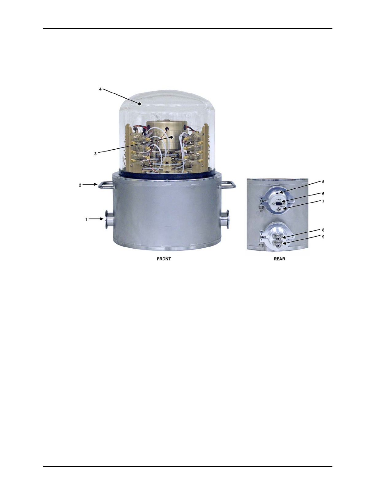
1.2.1 AMH-38
1. KF-40 vacuum connections (2)
2. Lifting handles (2)
3. Mass lifter and pneumatic actuation
solenoid valves
4. Vacuum bell jar (delivered with
PG7601 Platform)
Figure 1. AMH-38 Automated Mass Handler
5. AMH status indication LED
6. RS232 Port, COM1
7. DC power connection
8. Drive air pressure connection
9. Drive vacuum connection
© 2007 DH Instruments, a Fluke Company Page 2
Page 11
1. INTRODUCTION
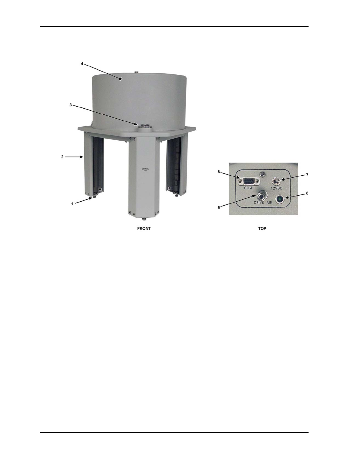
1.2.2 AMH-100
1. Platform engagement foot
2. Main mass manipulation column
3. Bubble level
4. Mass lifter and pneumatic
actuation cover
Figure 2. AMH-100 Automated Mass Handler
5. Drive air pressure connection
6. RS232 Port, COM1
7. DC power connection
8. AMH status indication LED
Page 3 © 2007 DH Instruments, a Fluke Company
Page 12

AMH-38™ AND AMH-100™ OPERATION AND MAINTENANCE MANUAL
1.3 SPECIFICATIONS
15 VDC @ 2 A, 30 W max. consumption
15 to 35 ºC
41 cm H x 37 cm W x 38 cm D (16.3 in. x 14.6 in. x 15 in.)
41 cm H x 41 cm W x 36 cm D (16.3 in. x 16.1 in. x 14.1 in.)
18 kg (40 lbs)
12 kg (25 lbs)
RS232 (COM1)
275 kPa (40 psi), ± 10%, minimal flow
550 kPa (80 psi), ± 10%, minimal flow
Quick connector equivalent to Swagelok QM Series (QM2-B-200),
Use with DESO (double end shut off) type stem
Quick connector equivalent to Swagelok QM Series (QM2-B-200),
Use with SESO (single end shut off) type stem only.
Power Requirements:
Operating Temperature:
Dimensions:
Weight:
Communications:
Drive Air Supply:
Vacuum Supply:
Pressure Connections:
CE conformance:
AMH-38:
AMH-100:
AMH-38:
AMH-100:
AMH-38:
AMH-100:
AMH-38 only: At least 50 kPa (7.5 pi) under atmosphere, minimal flow
Pressure:
Vacuum:
Available, must be specified
Due to a policy of continuous product improvement, all specifications are subject to change
without notice.
© 2007 DH Instruments, a Fluke Company Page 4
Page 13
22.
2. PREPARATION FOR OPERATION
.
P
RREEPPAARRAATTIIOONN FFOORR
P
O
PPEERRAATTIIOON
O
N
2.1 UNPACKING AND INSPECTION
AMH-38 and AMH-100 are delivered, along with their standard accessories, in a corrugated container
with foam cut outs to hold items in place.
Remove all parts from the shipping box. Be sure not to lose or discard the Accessory Kit.
Inspect all parts for damage. If damage is noted, report it to your Shipping & Receiving Department and
the delivering carrier for appropriate action.
Inspect for any missing components or accessories referring to Table 1 for AMH-38 or Table 2 for AMH-
100. Should any items be missing, contact DHI or your local DHI representative.
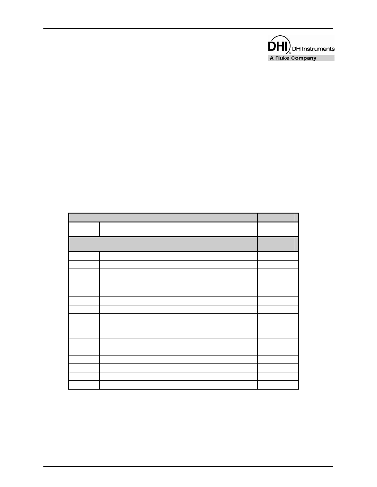
Table 1. AHM-38 Parts List
DESCRIPTION PART #
1 ea. AHM-38 Automated Mass Handler 402061 or
Accessory kit including: 402092 or
1 ea. Operation and Maintenance Manual 550133
1 ea. 15 VDC Power Supply 103986
1 ea. Power Cord 100770 or
1 ea. RS232 cable 100847 or
2 m. 1/8 in. PFA tubing 101392-Z
2 m. 1/4 in. PFA tubing 101450-Z
1 ea. Adaptor, 1/8 in. Swage x 1/4 in. NPT M 102189
1 ea. Tee, 1/4 in. Swage 101487
1 ea. Port Connector, 1/4 in. Swage 101984
1 ea. Quick Connector Stem, 1/8 in. Swage DESO (with red band) 402097
1 ea. Assembly: SESO Quick Connector Stem and Valve 402093
4 ea. Cable Tie, Hook and Loop 103485
1 ea. Tool, 3 mm Hex Wrench (with T handle) 103473
1 ea. O-ring, Viton, 2-273 103493
1 ea. Adaptor, 1/4 in. Swage x 1/4 in. NPT M 101477
402061-CE
402092-CE
100770-CE
100847-CE
Page 5 © 2007 DH Instruments, a Fluke Company
Page 14

AMH-38™ AND AMH-100™ OPERATION AND MAINTENANCE MANUAL
Table 2. AHM-100 Parts List
DESCRIPTION PART #
1 ea. AHM-100 Automated Mass Handler 402062 or
Accessory kit including: 402094 or
1 ea. Operation and Maintenance Manual 550133
1 ea. 15 VDC Power Supply 103986
1 ea. Power Cord 100770 or
1 ea. RS232 cable 100847 or
2 m. 1/8 in. PFA tubing 101392-Z
1 ea. Adaptor, 1/8 in. Swage x 1/4 in. NPTM 102189
1 ea. Quick Connector Stem, 1/8 in. Swage DESO (with red band) 402097
4 ea. Cable Tie, Hook and Loop 103485
1 ea. Tool, 3 mm Hex Wrench (with T handle) 103473
1 ea. Tool, 2.5 mm Hex Wrench (with straight handle) 102257
1 ea. Dust Cover 103503
402062-CE
402094-CE
100770-CE
100847-CE
© 2007 DH Instruments, a Fluke Company Page 6
Page 15

2. PREPARATION FOR OPERATION
2.2 SITE REQUIREMENTS
2.2.1 SITE
General site requirements are the same as for PG7000 piston gauge platforms (see the
PG7000 Operation and Maintenance Manual).
When planning the site for use of AMH, consider that the AMH mass handler will occasionally
be removed from the PG7000 Platform. A convenient place to put it down when it is removed
should be planned. In addition, it is more convenient to leave the pressure, power and other
utilities connected to the AMH when removing it so consider the length and path of these
lines.
2.2.2 GAS SUPPLIES
AMH-38 requires a compressed air source and a vacuum source (see Sections 2.2.2.1,
2.2.2.2).
AMH-100 requires a compressed air source only (see Section 2.2.2.1).
2.2.2.1 DRIVE AIR SUPPLY
The drive air supply provides power to operate the mass lifter and the binary
mass selector pins (see Section 3.1).
Drive air requirements are:
Flow rate: Very low, avoid restrictions or excessive length of connecting
tubing
Cleanliness: If air from a compressor is used it should be filtered and dried,
preferably with a filter regulator with a coalescing filter. The
recommendation is for a 5-micron filter upstream of a 0.01-micron
coalescing filter. The main concern is the elimination of humidity,
which could corrode the AMH pneumatic controls.
Drive air pressures required (± 10%) for different mass sets are listed in Table 3:
Table 3. Drive Air Pressure Requirement by Mass Set
MODEL MASS SET
AMH-38 MS-AMH-13 275 (40)
AMH-38 MS-AMH-25 275 (40)
AMH-38 MS-AMH-38 275 (40)
AMH-100 MS-AMH-40 275 (40)
AMH-100 MS-AMH-60 380 (55)
AMH-100 MS-AMH-80 450 (65)
AMH-100 MS-AMH-100 550 (80)
DRIVE AIR
[kPa (psi)]
Do not operate AMH with drive pressure lower than 275 kPa (40 psi).
Damage to the AMH could result.
Page 7 © 2007 DH Instruments, a Fluke Company
Page 16

AMH-38™ AND AMH-100™ OPERATION AND MAINTENANCE MANUAL
2.2.2.2 VACUUM SUPPLY (AMH-38 ONLY)
The vacuum supply is necessary for AMH-38 operation when there is vacuum in
the AMH-38 vacuum chamber and bell jar (absolute by vacuum mode PG7601
operation). The vacuum supply assures that the binary mass selection pins
remain in the correct position and evacuates internal AMH volumes to minimize
the likelihood of leaks into the reference vacuum.
The vacuum pump or vacuum supply for the pressure controller of the PG7601
system can be used for the AMH-38 vacuum supply.
Vacuum drive requirements are:
Flow rate: Very low, avoid restrictions or excessive length of connecting
tubing
Do not operate AMH-38 when using a PG7601 in “absolute by vacuum” mode
without having a vacuum supply connected to AMH-38. Always check that
AMH-38 is supplied with vacuum before establishing reference vacuum in the
AMH-38 vacuum chamber. Failure to do so may result in damage to the
binary mass pins and/or binary masses.
Vacuum pressure: At least 50 kPa (7.5 pi) under atmosphere
Do not plug the AMH drive vacuum connection. Use only a “SESO” type
quick-connector stem. Plugging the AMH drive vacuum connection will cause
serious damage to AMH internal components.
© 2007 DH Instruments, a Fluke Company Page 8
Page 17

2. PREPARATION FOR OPERATION
2.3 SETTING UP THE AMH FOR OPERATION
2.3.1 GENERAL CONSIDERATIONS
AMH-100 requires only three connections: drive air supply, electrical power, and RS232
cable for communications with PG7000 Platform. Consider these connections when setting
up the AMH-100.
AMH-38 requires at least three connections: drive air supply, electrical power, and RS232
cable for communications with PG7000 Platform. If the PG7000 on which the AMH-38 is
installed will be operated with a vacuum in the vacuum chamber, a drive vacuum connection
is also required. AMH-38 includes two KF40 connections that may be used for connection of
a vacuum pump and/or of an external vacuum gauge.
The AMH mass handler is removed from the PG7000 Platform to access the piston-cylinder.
Ease of removal and manipulation of the AMH should be considered in making the various
utility connections. In addition, a safe and convenient location to put it down when it is
removed should be planned.
2.3.2 SETTING UP THE AMH
To setup the AMH for operation, place the AMH bottom down on a sturdy, flat surface. Do
not install it on the PG7000 Platform until the AMH mass set has been installed and the AMH
itself has been it has been started up (see Section 2.7).
The setup of the AMH can be broken down into 6 steps:
• Connecting the drive air supply (see Section 2.3.2.1)
• Connecting the drive vacuum supply (AMH-38 only) (see Section 2.3.2.2)
• Connecting electrical power (see Section 2.3.2.3)
• Connecting PG7000 Platform communications (see Section 2.3.2.4).
• Connecting the reference vacuum supply (AMH-38 only) (see Section 2.3.2.5)
• Connecting an external vacuum gauge (AMH-38 only) (see Section 2.3.2.6).
There are two KF-40 pass throughs on the rear of the AMH-38 vacuum chamber for
electrical and pressure connections to the inside of the chamber. These are not intended
to be loosened or removed by the user. Only qualified service personnel should loosen the
KF- 40 pass through connections on the AMH-38 vacuum chamber.
2.3.2.1 CONNECTING THE DRIVE AIR SUPPLY
The AMH accessories kit includes hardware to facilitate the connection of the drive
air supply (see Tables 1, 2). Locate the drive air connection accessories including:
• Quick-connector stem (DESO type with red band).
• 2 m 1/8 in. O.D. clear PFA tubing.
• 1/8 in. Swage x 1/4 in. NPT M adaptor.
Page 9 © 2007 DH Instruments, a Fluke Company
Page 18

AMH-38™ AND AMH-100™ OPERATION AND MAINTENANCE MANUAL
To use the supplied accessories to make the AMH drive air supply connection
proceed as follows:
Connect the quick-connector to one end of the PFA tube. Loosen the 1/8 in.
Swage nut on the assembly slightly. Slip the PFA tube into the nut until it
stops. Tighten the nut to swage the tube.
Connect the other end of the PFA tube to an appropriate drive air supply (see
Section 2.2.2.1). If desired, use the 1/8 in. Swage x 1/4 in. NPT M adaptor.
Insert the quick-connector stem into the drive air connection quick-connector
(top connector, color coded with red band). Press firmly until the stem clicks
into place.
The quick-connector stem seals when disconnected so the drive air supply
may be applied before the quick-connector stem is inserted into the quickconnector.
Apply drive air pressure to the connection and check for leaks.
Do not operate AMH with drive pressure lower than 275 kPa (40 psi).
Damage to the AMH could result.
© 2007 DH Instruments, a Fluke Company Page 10
Page 19

2. PREPARATION FOR OPERATION
2.3.2.2 CONNECTING THE DRIVE VACUUM SUPPLY (AMH-38 ONLY)
The AMH-38 accessories kit includes hardware to facilitate the connection of the
drive vacuum supply (see Table 1). Locate the drive vacuum connection
accessories including:
• Quick-connector stem (with blue band) and three way sleeve valve assembly.
• 2 m 1/4 in. O.D. PFA tubing.
• 1/4 in. Swage x 1/4 in. NPT M adaptor.
• 1/4 in. Swage tee and 1/4 in. Swage Port Connector.
To use the supplied accessories to make the AMH drive vacuum supply
connection proceed as follows:
Connect the blue banded quick-connector/sleeve valve assembly to one end
of the PFA tube. Loosen the 1/4 in. Swage nut on the assembly slightly. Slip
the PFA tube into the nut until it stops. Tighten the nut to swage the tube.
Connect the other end of the PFA tube to an appropriate vacuum supply (see
Section 2.2.2.2). If desired, use the 1/4 in. Swage x 1/4 in. NPT M adaptor
and/or the 1/4 in. Swage Tee and Port Connector. The Tee and Port
Connector are particularly useful if the vacuum supply is from a DHI
PPC/MPC Vacuum Kit. Install the Tee on the vacuum pump side of the PFA
tube between the vacuum pump and the PPC or MPC, or where the vacuum
tube connects to the PPC or MPC.
Insert the quick-connector stem into the drive vacuum connection quick-
connector (color coded with blue band). Press firmly until the stem clicks
into place. Use only a “SESO” type stem (not self sealing).
Check that the three-way sleeve valve is in the GAUGE position (drive
vacuum not applied to the AMH-38). Apply drive vacuum and check for
leaks.
Do not plug the AMH drive vacuum connection. Use only a “SESO” type
quick-connector stem. Plugging the AMH drive vacuum connection will cause
serious damage to AMH internal components.
A drive vacuum supply must be connected to AMH-38 when using a PG7601
in “absolute by vacuum” mode. Always check that AMH-38 is supplied with
drive vacuum before establishing reference vacuum in the AMH-38 vacuum
chamber. Failure to do so may result in damage to the binary mass pins
and/or binary masses.
2.3.2.3 CONNECTING ELECTRICAL POWER
Connect the electrical power to the power connector on the AMH. Use the
supply pack provided in the AMH accessories. Power supply to the pack is 100 –
240V, 50/60 Hz.
When power is connected, the green LED near the electrical connector should
light and not flash. If the LED flashes, see Section 3.2.7. If the LED doesn’t
light, and you are sure power is connected, contact your DHI Authorized Service
Provider.
Page 11 © 2007 DH Instruments, a Fluke Company
Page 20

AMH-38™ AND AMH-100™ OPERATION AND MAINTENANCE MANUAL
2.3.2.4 CONNECTING PG7000 PLATFORM COMMUNICATIONS
Locate the 9 pin D-sub cable delivered with the AMH accessories.
The communications connection configuration depends upon whether the
PG7000 is being used with a PPC automated pressure controller.
AMH Communications Connection Without a PPC Automated Pressure
Controller
Connect the female end of the 9 pin D-sub cable to the AMH COM1 port.
Connect the male end of the 9 pin D-sub cable to the PG7000 COM3 port.
Set the PG7000 COM3 port to (see the PG7000 Operation and Maintenance
Manual):
− Baud rate: 9600
− Parity: None
− Data bits: 8
− Stop bits: 1
AMH Communications Connection With a PPC Automated Pressure
Controller
The AMH shares PG7000 COM3 with the PPC automated pressure controller.
Connect the female end of the 9 pin D-sub cable to the AMH COM1 port.
Connect the male end of the 9 pin D-sub cable to the PPC COM2 port.
Set the PPC COM2 port to (see the PG7000 Operation and Maintenance
Manual):
− Baud rate: 9600
− Parity: None
− Data bits: 8
− Stop bits: 1
Use another 9 pin D-sub cable to connect the PPC3 COM1 port to the PG7000
COM3 port.
Be sure that the COM3 port of the PG7000 Platform and the COM1 port of the
PPC have the same COM settings (see the PG7000 Operation and Maintenance
Manual).
2.3.2.5 CONNECTING A REFERENCE VACUUM SUPPLY (AMH-38 ONLY)
The AMH-38 vacuum chamber is equipped with two KF-40 vacuum connections.
One of these may be used as an alternate to the KF-25 connection built-in to the
PG7601 platform (see the PG7000 Operation and Maintenance Manual). This
may be desirable when a very low reference vacuum is desired, for example
when using a turbo molecular pump.
To use the KF-40 connection on the AMH-38 for the vacuum reference supply,
use a KF-40 vacuum hose. Plug the platform’s KF-25 connection. Consider the
need to shut-off the vacuum supply when vacuum is not desired in the vacuum
chamber and the need to remove the AMH-38 from the PG7601 Platform to
access the piston-cylinder module or the mass set.
© 2007 DH Instruments, a Fluke Company Page 12
Page 21

2. PREPARATION FOR OPERATION
2.3.2.6 CONNECTING AN EXTERNAL REFERENCE VACUUM GAUGE (AMH-38 ONLY)
The AMH-38 vacuum chamber is equipped with two KF-40 vacuum connections.
One of these may be used to connect an external vacuum gauge as an alternate
to the vacuum gauge built-in to the PG7601 platform. This may be desirable to
measure the reference vacuum with lower measurement uncertainty that the
PG7601’s internal vacuum gauge.
See the PG7000 Operation and Maintenance Manual for information on using an
external vacuum gauge to measure reference vacuum pressure.
2.4 PREPARING THE PG7000 PLATFORM
2.4.1 PREPARING PG7102, PG7202, PG7302 PLATFORM HARDWARE FOR AMH-100
Most PG7102, PG7202 and PG7302 Platforms delivered after 2004, January 1, are AMH
ready. AMH ready platforms have three machined holes in the top surface of the base
casting to seat the AMH-100 legs.
To prepare the AMH ready platform, loosen the three set screws on the sides of the base
casting until the screw is just past flush with the side (2.5 mm allen wrench). Remove the
two black plastic caps and the bubble level assembly, exposing the AMH-100 seating holes.
When AMH-100 is used, the bubble level on the AMH-100 center plate is used to level the
PG7000 system. Retain the casting level in case of future use of the platform without the
AMH accessory.
If your PG7102, PG7202 or PG7302 does not have the three AMH leg holes on the top
surface, the based casting must be replaced before AMH can be used with the platform.
Contact DHI or your local DHI representative.
2.4.2 PREPARING PG7601 PLATFORM HARDWARE FOR AMH-38
Most PG7601 platforms with a serial number higher than 124 are AMH ready. Serial
numbers 124 and lower (units delivered prior to 1994) may require a new vacuum plate. To
determine if a PG7601 vacuum plate is AMH ready, measure the width of the flat horizontal
surface from the outermost diameter of the plate to the inner chamfer. (see Figure 3) If this
width is 12.2 mm, the vacuum plate will accept AMH; if the width is 7.2 mm, the vacuum
place must be replaced. Contact a DHI Authorized Service Provider.
The vacuum plate of an AMH ready PG7601 must be inspected for damage prior to
attempting to install AMH-38. The AMH-38 vacuum chamber fits over the outside diameter of
the vacuum plate. Displaced material from
dents or dings on the outside corner of the
plate could increase the effective diameter
making it difficult or impossible for the
AMH-38 vacuum chamber to fit over the
plate. Inspect the outside diameter of the
vacuum plate (see Figure 3). Remove any
material on the outside surface and return
to a finish of approximately 0.8
micrometers or better. If you are not
comfortable performing this task with inhouse capabilities, contact an Authorized
DHI Service Provider.
Figure 1. PG7601 V a cuum Plate Detail
Figure 2. PG7601 V a cuum Plate Detail
Figure 3. PG7601 V a cuum Plate Detail
Figure 4. PG7601 V a cuum Plate Detail
Figure 5. PG7601 V a cuum Plate Detail
Figure 6. PG7601 V a cuum Plate Detail
Figure 7.
PG 7601 V acu um P late Det
Figure 3. PG7601 Vacuum Plate Detail
Page 13 © 2007 DH Instruments, a Fluke Company
Page 22

AMH-38™ AND AMH-100™ OPERATION AND MAINTENANCE MANUAL
2.4.3 VERIFYING PG7000 EMBEDDED SOFTWARE VERSION FOR AMH SUPPORT
To use a PG7000 Platform with AMH, the PG7000 Platform embedded software must
support AMH. PG7000 embedded software versions 2.05 or higher support AMH. The
software version can be viewed by pressing and holding the PG7000 [ESCAPE] key from the
main run screen.
If your PG7000 Platform is not running embedded software version 2.05 or higher, the
PG7000 embedded software must be upgraded before AMH can be used. For most
PG7000s, this can be accomplished by downloading a software flashing utility and the
embedded software from the DHI web site,
PG7000 Platforms running an embedded software version lower than 2.02 require hardware
changes to upgrade to version 2.05. Contact a DHI Authorized Service Provider to have this
service performed. Do not attempt to flash new software until the necessary hardware
upgrade has been performed.
www.dhinstruments.com.
2.5 CHECKING THE PG7000 PISTON-CYLINDER MODULES FOR AMH OPERATION
2.5.1 CHECKING THE PISTON CAP
The AMH mass handler lifts the mass loading bell completely off of the piston and lowers it
back down each time the mass load is changed. When adding AMH to an existing PG7000
system, it is important to check the outer circumference of the piston cap for displaced
material from dents or dings that might interfere with the free removal and replacement of the
bell. In this case, in particular, when the bell is lowered back onto the piston with little or no
additional mass, the weight of the bell alone may not cause it to seat properly on the piston
cap, which could cause poor performance.
Before using AMH with existing piston-cylinder modules, examine the outside circumference
of the piston cap (see Figure 4). Remove any material on the outside surface and return to a
finish of approximately 0.8 micrometers or better. Note that the piston mass is a calibrated
value so after removing material, the mass should be redetermined. Also, apply and wipe off
a very thin film of Krytox® lubricant on the inside surface of the top of the mass loading bell
where it contacts the outside perimeter of the piston cap (a tube of Krytox lubricant is
included in the PG7000 Platform accessories). If you are not comfortable performing this
task with in-house capabilities, contact an Authorized DHI Service Provider.
Test the piston-cylinder modules with the AMH mass set bell. To do this, install the pistoncylinder module and binary mass carrier on the PG7000 Platform (see the PG7000 Operation
and Maintenance manual). Then slip the AMH mass bell down over the binary mass carrier.
The bell should seat smoothly and easily. If you push the bottom of the seated bell to one
side, it should naturally and easily fall back to its normal seated position (see Figure 5). If the
bell does not seat easily and/or does not reseat naturally when pushed to one side, there is
likely to be difficulty operating AMH with the piston. If this cannot be corrected locally, the
piston-cylinder module should be returned to a DHI Authorized Service Provider.
© 2007 DH Instruments, a Fluke Company Page 14
Page 23

2. PREPARATION FOR OPERATION
Figure 4. Piston Cap Inspection
Figure 5. Piston Cap/Bell Testing
2.5.2 CHECKING PISTON STOP BUSHING
Piston-cylinder modules used with AMH must be
equipped with the newer style of piston stop bushing
that is threaded and made of white or cream colored,
static dissipative acetal. Before using a PG7000
piston-cylinder module with AMH, inspect the piston
stop bushing (see Figure 6). Verify that the bushing is
made of the required white or cream-colored material.
Black bushings must be replaced before the pistoncylinder module is used with AMH. Contact a your DHI
representative or a DHI Authorized Service Provider
for assistance.
To view the piston stop bushing, the piston cap must
be removed. See the PG7000 Operation and
Maintenance Manual; Piston-Cylinder Modules,
Disassembly, Cleaning and Maintenance.
Figure 6.
Piston-Cylinder Module
Piston Stop Bushing
2.6 INSTALLING THE AMH MASS SET
PG7000 AMH masses are shipped in reusable, molded shipping and storage cases. One of the cases
contains the binary masses, binary mass carrier, mass bell and lifting shaft/trim mass tray. The other
cases contain the main masses of 6.2 (AMH-38) or 10 kg (AMH-100) (see PG7000 Operation and
Maintenance Manual, Inspecting Contents, Mass Set for mass set composition detail). Each mass is
packed in a sealed plastic bag and then placed in a protective shipping insert.
The stability over time of PG7000 pressure measurements is a function of the stability of the
masses loaded on the piston. Precautions should be taken in handling the masses to minimize
influences that may change their mass. This includes always wearing protective gloves when handling
the masses to avoid contaminating them with body oils and perspiration. Protective gloves are
provided in the accessory kits of PG7000 Platforms.
Page 15 © 2007 DH Instruments, a Fluke Company
Page 24

AMH-38™ AND AMH-100™ OPERATION AND MAINTENANCE MANUAL
To install the AMH mass set, follow the order of operation below carefully (refer to Figure 7):
Prepare the masses: Open the shipping cases and remove all the masses and mass set elements
from their plastic bags.
Install a piston-cylinder module in the PG7000 Platform: See the PG7000 Operation and
Maintenance Manual, Installing a Piston-Cylinder Module Into the Platform.
Install the binary mass carrier: Place the pyramidal shaped carrier on top of the piston cap.
Install the mass loading bell: Slip the mass loading bell over the binary mass carrier and slide it
down until the inside top of the bell sits on the binary mass carrier.
Install the main mass discs: Load the main mass discs (6.2 kg each with AMH-38, 10 kg each with
AMH-100) onto the mass bell starting with mass #1 and loading in sequential order. Mass #1
should be at the bottom of the stack and the highest number mass at the top. The mass sequence
numbers are lazer marked on the top surface of each mass. Pass the mass disc over and down the
mass loading bell and center it on the ledge at the bottom of the bell. Load the rest of the main
masses, sequentially, onto the bottom mass.
Install the binary mass tubes: Load the binary mass tubes concentrically from the largest to
smallest, outside to inside. The largest, long tubes slip down between the main mass stack and the
bell and rest on the ledge at the bottom of the mass bell. The smaller masses load onto the
pyramidal steps of the binary mass carrier.
The mass loading process is complete: The mass set is in the all loaded position. The mass lifting
shaft/trim mass tray assembly is not yet installed. It will be attached after the AMH autmomated
mass handler is installed over the masses on the platform.
Create the mass set and mass loading bell in the PG Terminal: See the PG7000 Operation and
Maintenance Manual, Add Mass Set and Add Mass Loading Bell Sections.
SHOWN IS THE MS-AMH-38 MASS SET FOR THE AMH-38 MASS HANDLER. SMALLER MASS SETS MAY INCLUDE LESS
MAIN MASS DISCS. MASS SETS FOR THE AMH-100 MASS SET ARE IDENTICAL TO AMH-38 BUT THE MAIN MASSES
ARE LARGER 10 KG DISCS AND A 7TH BINARY MASS TUBE OF 6.2 KG IS INCLUDED.
Figure 7. AMH Mass Set
© 2007 DH Instruments, a Fluke Company Page 16
Page 25

2. PREPARATION FOR OPERATION
2.7 INITIAL START UP/VERIFICATION
Perform the initial verification of the AMH mass loading system with the AMH sitting on a flat surface next
to the PG7000 Platform. Do not install the AMH onto the platform until steps through below have
been completed.
To verify the AMH mass handler prior to installing it on the PG7000 Platform, proceed as follows:
Make the necessary pressure, power and communications connections: Complete the set up
procedure described in Section 2.3.2. Do not open the valve to apply vacuum to the AMH-38 until a
vacuum is being established in the vacuum chamber.
Do not operate AMH with drive pressure lower than 275 kPa (40 psi). Damage to the AMH could
result.
Insert the mass lifting shaft into the AMH: Insert the shaft into the hole in the center of the AMH
mass lifter and slide it down until the trim mass tray sits on the top of the lifter. This arrangement trips
the AMH’s internal proximity sensor allowing the AMH system to be operated off of the PG7000
Platform without an actual mass load.
Select an AMH mass set and mass bell as the active mass set and bell for the PG7000: This
step can be skipped if the AMH mass set and bell have already been selected, if so go directly to step
. On the PG Terminal, press [SPECIAL], <1PC/MS>, <3mass bell>, <5select> and select the
mass bell of the AMH mass set. Using [SPECIAL], <1PC/MS>, <2mass set>, <5select>, select an
AMH mass set (mass set designated by S/N nnnnA). Selecting the AMH mass set causes the
PG7000 Platform to attempt to establish communication with the AMH system. If the communication
fails, an error message occurs (see Sections 3.2.8, 6).
If communication succeeds, the PG7000 initializes the AMH mass handler. The trim mass tray should
rise approximately 2.5 cm (1 in.) above the top of the lifter; followed by the sound of the main mass
selection columns rotating. Then the trim mass tray should be lowered back down. The steps of this
procedure are commented on the PG Terminal display as they execute. If the sequence does not
complete and/or any error messages are observed, see Section 6 and Table 4 for troubleshooting
assistance. If the sequence completes, the AMH system has been cleared and put into a known
state in which all mass holding ledges and pins are retracted so that it can safely be slipped down
over the AMH mass set and installed on the PG7000 Platform.
The PG7000 Platform must be able to initialize the AMH system before start up can proceed.
Clear the AMH and test its operation: Press [SPECIAL], <8AMH>, <2control>, <3loadall>. The
trim mass tray should rise approximately 2.5 cm (1 in.) above the top of the lifter, followed by the
sound of the main mass selection columns rotating. Then the trim mass tray should be lowered back
down. The steps of this procedure are commented on the PG Terminal display as they occur. If the
sequence does not complete and/or any error messages are observed, see Section 6 and Table 4 for
troubleshooting assistance. If the sequence completes, the AMH mass handler has been cleared
and put into a known state in which all mass holding ledges and pins are retracted so that it can
safely be slipped down over the mass set and installed on the PG7000 Platform.
If desired, visually inspect the condition of the AMH mass handler by carefully tipping the AMH to look
inside. The main mass selection columns should have their all flat surfaces (no ledges) oriented
towards the center and all binary mass selection pins should be retracted (see Section 3.1).
When this step is complete, the AMH mass handler is ready to be installed on the PG7000 Platform
(see Section 3.2.1).
Page 17 © 2007 DH Instruments, a Fluke Company
Page 26

AMH-38™ AND AMH-100™ OPERATION AND MAINTENANCE MANUAL
N
N
OOTTEES
S
© 2007 DH Instruments, a Fluke Company Page 18
Page 27

3. OPERATION
33.
.
O
PPEERRAATTIIOON
O
N
3.1 GENERAL OPERATING PRINCIPLES
Numerical reference in this section refers to Figure 8.
The purpose of the AMH-38 or AMH-100 system is to automatically load specified values of mass onto
the PG7000 piston. This is accomplished by lifting the complete mass set up off and above the pistoncylinder to the mass selection position, selecting the individual masses to be loaded and retained, and
then placing the masses to be loaded back onto the piston.
To accomplish the mass lifting, selection and lowering function, the AMH mass handler uses four main
sub-systems. These systems are present in both the AMH-38 and AMH-100 models.
1. Electronic and electrical controls(7): The AMH electronic and electrical controls are located
just above the mass lifter, under a protective cap. These support the AMH operating logic, a
proximity sensor to detect mass load position, reading of the main mass selection column
switches, operation of the column rotating motor and actuation of the pneumatic control solenoid
valves.
2. Mass lifter(8): The mass lifter is used to lift the entire mass load to the mass selection position
and then to lower the selected masses onto the piston. The mass lifter is pneumatically actuated.
A flexible diaphragm(4) is connected to a lifting assembly(5). A three-way solenoid valve (e.g. 9)
can be actuated to admit or exhaust drive air pressure to and from the volume under the
diaphragm. Admitting drive pressure forces the lifting assembly up. Exhausting the pressure
lowers it. With AMH-38, the pressure is exhausted outside the vacuum chamber, to the AMH
drive vacuum supply when there is vacuum in the chamber.
As the mass lifting assembly (5) rises, it engages a ledge on the mass lifting shaft(6), pushing it
up. The mass lifting shaft is connected to the binary mass carrier(10) and the mass bell(1) sits
on the binary mass carrier. As the mass lifting shaft goes up, it lifts the binary carrier and the bell,
which in turn lifts the main masses(14) and the binary mass tubes(2). When the lifting assembly
reaches the top of its stroke, the entire mass load is lifted completely off the piston cap(12) and
the masses are in the mass selection position. In this position, the ledges on the main mass
selection columns(13) align with the gaps between the main masses and the binary mass
selector pins(e.g. 3) align with the holding grooves in the binary mass tubes. When gas is
exhausted from the volume under the lifting assembly, it descends, lowering the selected masses
onto the piston.
3. Main mass disc selection columns(13): The three main mass selection columns are used to
retain the main mass discs(14) that are not to be loaded onto the piston. The columns are
rotated synchronously by a DC motor and a drive belt(11). Contact switches are used to monitor
the column position. Each column has a number of sides equal to the maximum number of main
masses plus one (six sides for AMH-38, ten sides for AMH-100). One side, which retains all the
masses so that none are loaded, has a ledge for each mass. Each subsequent side has one less
ledge, moving from the bottom up. The last side has no ledges and is used to select all the main
masses for loading. When the mass load is lifted to the mass selection position, the motor is
operated to rotate the columns to retain the desired number of masses. The rest of the main
masses are free and are lowered onto the piston when the lifting assembly descends.
Page 19 © 2007 DH Instruments, a Fluke Company
Page 28

AMH-38™ AND AMH-100™ OPERATION AND MAINTENANCE MANUAL
4. Binary mass tube selection pins(3): The binary mass selection pins are used to retain the
binary mass tubes that are not to be loaded onto the piston. Three pins for each mass are
located in a circular pattern around the top of each mass. The pins are pneumatically actuated
and double acting. Two three-way solenoid valves(e.g. 9) control drive pressure to each set of
three pins. One valve admits pressure to one side of the pin to extend it and the other admits
pressure to the other side of the pin to retract it. Once the pins have been moved, the pressure is
exhausted; the exhaust is to vacuum when there is vacuum in the vacuum chamber of AMH-38.
When the mass load is lifted to the mass selection position, the pins are operated to retain the
binary masses that are not to be loaded. The rest of the binary masses are free and are placed
onto the piston when the lifting assembly descends.
Do not put your fingers or anything else beneath the AMH trim mass tray. AMH may lower up
to 100 kg (220 lbs) onto anything that is under the trim mass tray. This could cause
damage and/or injury.
© 2007 DH Instruments, a Fluke Company Page 20
Page 29

3. OPERATION
1. Mass loading bell
2. Binary mass tubes
3. Binary mass selection pins
4. Flexible diaphragm
5. Mass lifting assembly
6. Lifting ledge on mass lifting shaft
7. Electronics and electrical controls
Figure 8. AMH Schematic/Operating Principle
Page 21 © 2007 DH Instruments, a Fluke Company
8. Mass lifter
9. Solenoid valve
10. Binary mass carrier
11. Main mass column rotation belt
12. Piston cap
13. Main mass column
14. Main masses
Page 30

AMH-38™ AND AMH-100™ OPERATION AND MAINTENANCE MANUAL
3.2 OPERATION
Once the AMH mass set has been installed (see Section 2.6) and the AMH mass handling system has
been initialized (see Section 2.7) and installed, regular operation of the AMH is controlled by the P7000
Platform in response to local commands entered on the PG Terminal or remote commands received over
the PG7000 Platform’s COM1 or IEEE-488 interface.
Generally, AMH operation is transparent to the operator. The AMH system changes the mass load on
the piston automatically as needed when a pressure or mass load setting command is given to the
PG7000. The AMH mass handler and mass set are removed only when it is necessary to access the
piston-cylinder assembly, for example to change ranges.
Subsections of this section describe various aspects of AMH operation.
See Sections 3.2.1 and 3.2.2 for instructions on installing and removing the AMH mass handler.
See Section 3.2.3 for information on regular pressure to mass or mass to pressure operation.
See Section 3.2.4 for information on controlling the AMH mass handling system directly, outside of
pressure to mass or mass to pressure operation.
See Section 3.2.5 for information on making and breaking the reference vacuum in AMH-38.
See Section 3.2.6 for information on accessing the piston-cylinder module when an AMH is installed.
See Section 2.3.7 and 3.2.8 for a description of the indications of the AMH LED and a listing of AMH
related error messages.
See Section 4 for information on controlling PG7000 equipped with AMH by remote commands from a
computer.
3.2.1 INSTALLING THE AMH MASS HANDLER ON THE PG7000 PLATFORM
To avoid possible damage to the AMH automated mass handler, always perform the
initial start/verification procedure described in Section 2.7 BEFORE attempting to install
AMH on the PG7000 Platform. Failing to do so, may result in attempting to install AMH
with mass selection columns or pins in the incorrect position, which can damage the
AMH mass handler.
© 2007 DH Instruments, a Fluke Company Page 22
Page 31

3. OPERATION
Figure 9. AMH Installation on PG7000 Platform
3.2.1.1 INSTALLING AMH-38
To install the AMH-38 mass handler on the PG7601 platform, proceed as follows
(see Figure 9).
Prepare the AMH-38: Perform the AMH start up/verification procedure
describe in Section 2.7. This assures that the AMH mass selection columns
and pins are all correctly positioned.
Make sure that the mass lifting shaft is NOT installed on the mass bell.
If the KF-40 port on the side of the AMH is being used for the vacuum
reference connection, consider waiting to connect it after the AMH is on the
PG7601 platform.
Check that the large O-ring at the bottom inside circumference of the AMH-
38 vacuum chamber is well seated.
Lift the AMH-38 onto the PG7601 platform: Using the handles on the side of
the AMH-38 vacuum chamber, lift the AMH-38 above the PG7601 platform and
masses. Center it over the mass load and gently lower it down until the bottom
circumference of the AMH-38 vacuum chamber reaches the PG7601 vacuum
Page 23 © 2007 DH Instruments, a Fluke Company
Page 32

AMH-38™ AND AMH-100™ OPERATION AND MAINTENANCE MANUAL
plate. Check that the vacuum chamber is well aligned on the vacuum plate.
The AMH may be rotated on the platform to the most convenient position.
Install the mass lifting shaft: Slip the threaded end of the shaft down through
hole in the center of the mass lifter. Thread the shaft into the binary mass
carrier by holding and rotating the trim mass tray. NOTE THAT SHAFT HAS A
LEFT HAND THREAD SO IT MUST BE ROTATED COUNTER-CLOCKWISE
TO TIGHTEN IT. Use the 3 mm allen wrench supplied in the AMH-38
accessories to tighten the assembly until you feel the mass start to rotate.
Be sure that the mass lifting shaft is fully threaded into the binary
mass carrier. Thread it by hand, then tighten it using the allen wrench
supplied with the AMH-38 until you feel the masses rotate. If the
mass lifting shaft is not fully threaded, the mass will not align properly
with the AMH mass handling columns and pins and damage may result.
Install the bell jar: Install the PG7601 Pyrex® bell jar over the upper
portion of the AMH mass handler. Make the reference vacuum connection
if the KF40 connection on the side of the AMH is being used.
If preparing to operate w ith vacuum in the AMH-38 bell jar, open the
AMH vacuum supply valve to admit drive vacuum to the AMH-38 (see
Section 2.3.2.5). If operating without vacuum in the AMH-38 bell jar,
vent the AMH-38 vacuum supply port atmosphere.
Do not operate AMH-38 when using a PG7601 in “absolute by vacuum” mode
without having a vacuum supply connected to AMH-38. Always check that
AMH-38 is supplied with vacuum before establishing reference vacuum in the
AMH-38 vacuum chamber. NEVER plug the AMH drive vacuum port. Failure
to do so may result in damage to the binary mass pins and/or binary
masses (see Section 2.3.2.5).
The PG7601 with AMH-38 is now ready to operate (see Section 3).
3.2.1.2 INSTALLING AMH-100
To install the AMH-100 mass handler on the PG7000 Platform, proceed as
follows (see Figure 9).
Prepare the AMH-100 and PG7000 Platform: Perform the AMH start
up/verification procedure describe in Section 2.7. This assures that the
AMH mass selection columns and pins are all correctly positioned.
Loosen the set screws that are across from the AMH mounting holes on the
PG7000 vertical sides. Use a 2.5 mm allen wrench to loosen the set
screws until they extend just beyond side of the PG7000 Platform.
Make sure that the mass lifting shaft is NOT installed on the mass bell.
Lift the AMH-100 onto the PG7000 Platform: Grasping the AMH-100 by
the horizontal platform in its middle, lift the AMH-100 above the PG7601
platform and masses. Align it so that the bubble level on the AMH is at the
front of the PG7000 Platform. Center it over the mass load and gently lower
it down until the AMH feet enter the holes in the PG7000 Platform. Assure
that all three feet fully enter and seat in the platform holes. Tighten the
platform set screws using a 2.5 mm allen wrench provided in the AMH-100
accessories, one for each of the feet.
© 2007 DH Instruments, a Fluke Company Page 24
Page 33

3. OPERATION
Install the mass lifting shaft: Slip the threaded end of the shaft down through
hole in the center of the mass lifter. Thread the shaft into the binary mass
carrier by holding and rotating the trim mass tray. NOTE THAT SHAFT HAS A
LEFT HAND THREAD SO IT MUST BE ROTATED COUNTER-CLOCKWISE
TO TIGHTEN IT. Use the 3 mm allen wrench supplied in the AMH-100
accessories to tighten the assembly until you feel the masses begin to rotate.
Be sure that the mass lifting shaft is fully threaded into the binary
mass carrier. Thread it by hand, then tighten it using the allen wrench
supplied with the AMH-100 until you feel the masses rotate. If the
mass lifting shaft is not fully threaded, the mass will not align properly
with the AMH mass handling columns and pins and damage may result.
The PG7000 with AMH-100 is now ready to operate (see Section 3).
3.2.2 REMOVING THE AMH MASS HANDLER FROM THE PG7000 PLATFORM
3.2.2.1 REMOVING AMH-38
To remove the AMH-38 mass handler from the PG7601 platform, proceed as
follows (see Figure 9).
Load all the mass: Use [SPECIAL], <8AMH>, <2control>, <3loadall> to
load all the masses of the AMH mass set. This assures that no masses are
retained in the AMH so it will be able to be lifted off the platform freely.
Open the vacuum chamber and bell jar to atmospheric pressure:
Check that the vacuum chamber and bell jar are open to atmosphere. It is
not possible to remove the AMH with internal pressure less than
atmospheric pressure.
Remove the bell jar: Remove the PG7601 Pyrex® bell jar and set aside. If
the KF-40 connection on the side of the AMH vacuum chamber is being
used for the vacuum reference, consider disconnecting it before lifting the
AMH off the platform.
Remove the mass lifting shaft: Use the 3 mm allen wrench supplied in the
AMH-38 accessories to loosen and unscrew the shaft. NOTE THAT
SHAFT HAS A LEFT HAND THREAD SO IT MUST BE ROTATED
CLOCKWISE TO LOOSEN IT. Slip the shaft up and out of the mass
handler.
Lift the AMH-38 off of the PG7601 platform: Using the handles on the
side of the AMH-38 vacuum chamber, lift the AMH-38 straight up until it
clears the masses and set it on a flat surface. The AMH-38 mass handler
weighs about 18 kg (40 lb.).
3.2.2.2 REMOVING AMH-100
To remove the AMH-100 mass handler from the PG7000 Platform, proceed as
follows (see Figure 9).
Load all the mass: Use [SPECIAL], <8AMH>, <2control>, <3loadall> to
load all the masses of the AMH mass set. This assures that no masses are
retained in the AMH so it will be able to be lifted off the platform freely.
Loosen the mass handler column set screws: Loosen the set screws that
are across from the AMH mass selection columns on the PG7000 Platform
Page 25 © 2007 DH Instruments, a Fluke Company
Page 34

AMH-38™ AND AMH-100™ OPERATION AND MAINTENANCE MANUAL
vertical sides. Use the 2.5 mm allen wrench supplied in the AMH accessories
to loosen the set screws until they extend just beyond side of the PG7000
Platform.
Remove the mass lifting shaft: Use the 3 mm allen wrench supplied in the
AMH-38 accessories to loosen and unscrew the assembly. NOTE THAT
SHAFT HAS A LEFT HAND THREAD SO IT MUST BE ROTATED
CLOCKWISE TO LOOSEN IT. Slip the shaft up and out of the mass
handler.
Lift the AMH-100 off of the PG7000 Platform: Grasping the AMH-100 by
the horizontal platform in its middle, lift the AMH-100 straight up until it
clears the masses and set it on a flat surface. The AMH-100 mass handler
weighs about 12 kg (25 lb.).
3.2.3 REGULAR MASS TO PRESSURE OR PRESSURE TO MASS OPERATION
See the PG7000 Operation and Maintenance Manual, General Operation, for details on
PG7000 operation. If the PG7000 is equipped with AMH, AMH automatically loads the
requested mass values transparently to the operator.
Generally, the PG7000 is used to set pressures by loading mass onto the piston and
adjusting the pressure under the piston to float the piston. The PG7000 supports this
operation locally from its main run screen in pressure entry or mass entry mode (see the
PG7000 Operation and Maintenance Manual, [M or S]). In pressure entry mode, when AMH
is installed and initialized, when the operator enters the pressure to set, the corresponding
mass load is loaded automatically with the AMH’s 0.1 kg mass loading resolution. If the
PG7000 is set for finer than 0.1 kg resolution (see the PG7000 Operation and Maintenance
Manual, [RES], the operator is prompted to load a trim mass value manually. In mass entry
mode, if a mass value with resolution higher than 0.1 kg is entered, after AMH loads the
value within 0.1 kg, the operator is prompted to load the remaining trim mass value manually.
Do not put your fingers or anything else beneath the AMH trim mass tray. AMH may
lower up to 100 kg (220 lbs) onto anything that is under the trim mass tray. This could
cause injury and/or damage.
3.2.4 DIRECT CONTROL OF AMH FUNCTIONS
In normal PG7000 operation, the AMH mass handler is operated transparently to the
operator when a mass change is necessary.
For AMH to be operated it must first be initialized by selecting an AMH mass set (see
PG7000 Operation and Maintenance Manual, Select Mass Set.
The status of the AMH (current masses loaded) can be viewed and its operation controlled
directly using [SPECIAL], <8AMH>.
Select <1status> to view which AMH masses are loaded.
Select <2control>, <1up/down> to raise and lower the mass load without changing the
selected masses.
Select <2control>, <2discreet> to select specific masses to load and unload.
Select <2control>, <3loadall> to clear the AMH and load all the masses on the piston. This
is the condition used to remove and install the AMH. In this state, the AMH retains no
masses.
Select <2control>, <1unloadall> to clear the AMH and unload all the masses from the
piston. In this state, the AMH retains all the masses.
© 2007 DH Instruments, a Fluke Company Page 26
Page 35

3. OPERATION
3.2.5 MAKING AND BREAKING THE REFERENCE VACUUM (AMH-38 ONLY)
When making and breaking the reference vacuum in the AMH 38 vacuum chamber to switch
the PG7000 between absolute and gauge mode operation, it is important that the AMH mass
manipulation actuators also be exposed to the correct pressure. The correct pressure is
vacuum in absolute mode and atmosphere in gauge mode.
If AMH-38 is to be operated with a vacuum in its vacuum chamber, a vacuum supply must be
connected to the drive vacuum connection quick connector so that the AMH actuators (mass
lifter, mass selector pins) are evacuated when they are not pressurized. See Section 2.3.2.2
for information on correctly connecting the drive vacuum supply to AMH-38.
When using AMH-38 in absolute mode, the drive vacuum supply sleeve valve must be set to
the VACUUM position just before establishing the reference vacuum.
When operating with atmosphere in the vacuum chamber, set the drive vacuum supply
sleeve valve to GAUGE so that the AMH actuators vent to atmosphere.
Failure to supply vacuum to the AMH-38 before establishing a vacuum in its vacuum
chamber may cause unexpected operation of the binary mass selector pins which could
result in damage to the AMH mass handler and or masses (see Section 2.3.2.5). NEVER
plug the AMH drive vacuum port.
3.2.6 ACCESSING THE PG7000 PISTON-CYLINDER MODULE
To access the piston-cylinder module in a PG7000 Platform with AMH installed, the AMH
mass handler and mass set must be removed.
First, remove the AMH mass handler as described in Section 3.2.2.
Then, remove the AMH mass set following the instructions in Section 2.6 in reverse order.
Once the AMH mass handler and mass set are removed, the piston-cylinder module can be
accessed and removed by simply unscrewing it from the mounting post following the
standard procedure (see the PG7000 Operation and Maintenance Manual).
3.2.7 INDICATOR LED
There is a green indicator LED located on AMH-38 and AMH-100 near the power supply
connection. It is on the rear electrical, vacuum chamber pass through of AMH-38 and on the
top cover of AMH-100 (see Figures 1, 2).
The indicator has four possible conditions:
• Off: AMH is not powered.
• Solid green: AMH is powered and operation is normal.
• Slow flashing green: AMH is powered and is in an unknown state. To recover use
[SPECIAL], <8AMH>, <2control>, <3loadall> or <4unloadall> or initialize AMH by
selecting an AMH mass set (see Section 2.7., Step ).
• Fast flashing green: AMH is powered and has encountered a known error condition.
The error is displayed on the PG Terminal (see Section 3.2.8) and available remotely
using the “AMHERR” command. To recover use [SPECIAL], <8AMH>, <2control>,
<3loadall> or <4unloadall> or initialize AMH by selecting an AMH mass set (see Section
2.7, Step ).
Page 27 © 2007 DH Instruments, a Fluke Company
Page 36

AMH-38™ AND AMH-100™ OPERATION AND MAINTENANCE MANUAL
3.2.8 ERROR MESSAGES
The AMH mass handler can inform the PG7000 of certain error conditions.
An AMH error condition is indicated on the PG Terminal by an error message and listing of
the error number on the bottom right hand of the display.
An AMH error is indicated remotely by the PG7000 return string including the character “E” in
the third “Ready indicator position”. The “Ready” indication is included in the “PR” and
“STATUS” commands. When an “E” has been returned, the error identification can then be
retrieved using the “AMHERR” command. See the PG7000 Operation and Maintenance
Manual, Remote Operation for additional information.
The possible errors are listed in table 4.
Table 4. AMH Errors
AMH
ERROR
NUMBER
None
(Remote
error #29)
None
(Remote
error #28)
2 None Text argument is too long.
6 None Argument out of range.
7 None Missing or improper argument.
9 None Unknown Command.
10 None Invalid command suffix.
13 None Receive buffer overflow. Buffer has been flushed.
18 None Command not available.
60 None Watchdog reset has occurred.
100 None Present mass setting unknown.
102 None 6.2 kg binary mass not available on AMH-38.
103
104
105
106 None Mass load must first be lifted.
107
108
110
111
112
113
114
115
116
117
118
119
PG TERMINAL MESSAGE COMMENT
<AMH response fault>
<AMH not responding>
<AMH memory failure>
<AMH memory failure>
<AMH logic failure>
<AMH logic failure>
<AMH logic failure>
<AMH unable to rotate column
motor>
<AMH unable to rotate column
motor>
<AMH unable to rotate column
motor>
<AMH unable to rotate column
motor>
<AMH logic failure>
<AMH logic failure>
<AMH logic failure>
<AMH logic failure>
<AMH logic failure>
<AMH logic failure>
The AMH has returned a string that the PG7000 cannot
identify. This is a PG7000 generated error.
The PG7000 has not received a response from the AMH.
This is a PG7000 generated error as a consequence of a time
out while attempting to communicate with AMH.
Mass memory.
Non-volatile memory is corrupt.
Fatal electronics error.
Incorrect CPLD version.
CPLD logic error.
Column motor switch error on column 0 (C0).
Column motor switch error on column 1 (C1).
Column motor switch error on column 2 (C2).
Wrong column switch detected.
JTAG buffer overflow.
JTAG max retries.
JTAG TDO mismatch.
JTAG illegal state.
JTAG ENDxR state unknown.
JTAG unknown error.
© 2007 DH Instruments, a Fluke Company Page 28
Page 37

3. OPERATION
Table 4. AMH Errors (continued)
AMH
ERROR
NUMBER
120
121
122
123
124
125
126
130
131
132
133
134
135
136
137
138
139
140
141
142
143
PG TERMINAL MESSAGE COMMENT
<AMH unable to lift mass load>
<AMH unable to lower mass load>
<AMH unable to lift mass load>
<AMH unable to lower mass load>
<AMH unable to lift mass load>
<AMH unable to rotate column
motor>
<AMH unable to rotate column
motor>
<AMH valve failure>
<AMH valve failure>
<AMH valve failure>
<AMH valve failure>
<AMH valve failure>
<AMH valve failure>
<AMH valve failure>
<AMH valve failure>
<AMH valve failure>
<AMH valve failure>
<AMH valve failure>
<AMH valve failure>
<AMH valve failure>
<AMH valve failure>
Mass lift valve not sensed.
Mass is dropping unexpectedly.
Mass never lifted.
Mass is not dropping when it should.
IR beam malfunction. AMH will not attempt lift
Column motor switch on column 1 is misaligned.
Column motor switch on column 2 is misaligned.
6.2 kg binary mass pin engage valve (VLV#14) not sensed.
3.2 kg binary mass pin engage valve (VLV#6) not sensed.
1.6 kg binary mass pin engage valve (VLV#12) not sensed.
0.8 kg binary mass pin engage valve (VLV#4) not sensed.
0.4 kg binary mass pin engage valve (VLV#10) not sensed.
0.2 kg binary mass pin engage valve (VLV#2) not sensed.
0.1 kg binary mass pin engage valve (VLV#8) not sensed.
6.4 kg binary mass pin disengage valve (VLV#15) not
sensed.
3.2 kg binary mass pin disengage valve (VLV#7) not sensed.
1.6 kg binary mass pin disengage valve (VLV#13) not
sensed.
0.8 kg binary mass pin disengage valve (VLV#5) not sensed.
0.4 kg binary mass pin disengage valve (VLV#11) not
sensed.
0.2 kg binary mass pin disengage valve (VLV#3) not sensed.
0.1 kg binary mass pin disengage valve (VLV#9) not sensed.
Page 29 © 2007 DH Instruments, a Fluke Company
Page 38

AMH-38™ AND AMH-100™ OPERATION AND MAINTENANCE MANUAL
N
N
OOTTEES
S
© 2007 DH Instruments, a Fluke Company Page 30
Page 39

4. REMOTE OPERATION
.
44.
4.1 OVERVIEW
The AMH mass handling system is equipped with an RS232 interface (COM1). The interface is used for
communications between the AMH mass handler and the PG7000 Platform’s COM3 (directly, or through
a DHI pressure controller). The AMH mass handler is not intended to be addressed directly with remote
commands from a computer. Its functionality is achieved by commands addressed to the PG7000
Platform. For example, sending a “PS=” command to the PG7000 Platform when an AMH is already
initialized, causes the AMH to load mass automatically. Certain AMH specific commands can be sent to
the PG7000 Platform, for example a command to clear the AMH and load all the mass on the piston.
These commands are listed in the PG7000 Operation and Maintenance Manual, Remote Operation along
with the other PG7000 remote commands.
MOOTTEE
RREEM
OOPPEERRAATTIIOONN
Page 31 © 2007 DH Instruments, a Fluke Company
Page 40

AMH-38™ AND AMH-100™ OPERATION AND MAINTENANCE MANUAL
N
N
OOTTEES
S
© 2007 DH Instruments, a Fluke Company Page 32
Page 41

55.
5. MAINTENANCE AND ADJUSTMENTS
.
M
AAIINNTTEENNAANNCCEE AANNDD
M
A
DDJJUUSSTTMMEENNTTS
A
S
5.1 MAINTENANCE
The AMH mass handler is designed for long term, maintenance free operation.
Certain day-to-day procedures are required for proper operation.
• Lubricate the threads of the mass lifting shaft: Occasionally, and especially after cleaning,
lubricate the threads on the bottom of the mass lifting shaft. Wipe on a very thin film of Krytox®
grease (supplied with the PG7000 Platform accessories). Wipe off all excess grease.
• Lubricate the inside of the mass bell: Occasionally perform the bell positioning test described
in Section 2.5.1. If the test fails, or if any sign of the bell not disengaging and engaging from the
piston when the mass load is lifted is observed in operation, apply and wipe off a very thin film of
Krytox® grease (supplied with the PG7000 Platform accessories) to the inside surface of the top
of the mass loading bell where it contacts the outside perimeter of the piston cap.
If AMH returns no errors and no operational issues are observed, no regular maintenance is required. To
avoid any planned downtime, an AMH overhaul is recommended every 10000 hours of operation or three
years. Contact a DHI Authorized Service Provider to have this service performed.
Page 33 © 2007 DH Instruments, a Fluke Company
Page 42

AMH-38™ AND AMH-100™ OPERATION AND MAINTENANCE MANUAL
N
N
OOTTEES
S
© 2007 DH Instruments, a Fluke Company Page 34
Page 43

6. TROUBLESHOOTING
66.
.
T
RROOUUBBLLEESSHHOOOOTTIINNG
T
G
Identify the symptom or unexpected behavior you are observing from the SYMPTOM list below.
A PROBABLE CAUSE is provided and a SOLUTION is proposed including references to manual
sections that provide information that may be of assistance.
This troubleshooting guide is for the AMH mass handler. For general PG7000 troubleshooting, see the
PG7000 Operation and Maintenance Manual.
Table 5. AMH Troubleshooting Checklist
SYMPTOM PROBABLE CAUSE SOLUTION
PG Terminal displays <AMH not
responding>.
PG Terminal displays <AMH unable
to lift mass load ERR#122>.
Mass handling system will not go down
over the masses to be installed on the
platform.
AMH masses rock back and forth
when lifted to the mass selection
position.
Main masses move when mass is in
mass selection position and main
mass selection columns are rotating.
PG Terminal displays <AMH unable
to rotate column motor> and
ERR#110, ERR#111 or ERR#112.
Poor behavior of PG7000 with
symptoms such as inconsistent
indication of piston position, unstable
pressure when piston is floating.
Mass handling error occurs with AMH38 in absolute mode due to binary
mass selection pins being extended
when they should be retracted.
Cannot remove bell jar from AMH-38
though there is no vacuum in the bell
jar.
When setting pressures, PG Terminal
stops to instruct to load masses rather
than completing all mass loading
automatically.
PG Terminal displays a message and
<ERR #nnn> on the bottom right hand
corner.
PG7000 is unable to establish
communications with the AMH mass
handler due to incorrect cable connection
or COM port settings.
AMH mass lifter is unable to lift mass load
fully up to the mass selection position.
Drive air pressure is too low or flow to
AMH is excessively restricted.
Main mass columns are not in correct
position because AMH has not been
properly prepared for installation.
AHM is not correctly seated on the
PG7000 Platform and is misaligned
relative to the mass load.
The mass lifting shaft is not fully threaded
into the binary mass carrier or the trim
mass tray has become loose from the
mass lifting shaft.
Mechanical interface between mass bell
and piston cap is not operating well
causing bell not to seat properly on piston
when AMH lowers mass.
Operating with a vacuum reference in the
vacuum chamber without applying drive
vacuum to the AMH. Operating with drive
vacuum port plugged.
When vacuum drive is applied to the AMH
without vacuum in the vacuum chamber,
vacuum may leak through the tubular
mass pin actuators and accumulate in the
vacuum chamber.
PG7000 pressure setting resolution is set
finer than 0.1 kg.
An AMH error has occurred. Determine AMH error in Table 4. Reset
Check that the correct cables are being used
to make the interface connections between
the PG7000 and the AMH (and PPC if a
pressure controller is present), that the
cables are connected to the correct ports
and that the COM ports are set correctly.
2.3.2.4
Increase drive air pressure and improve
drive air flow conditions. 2.2.2.1, 2.3.2.1
Perform the AMH start up/verification
procedure prior to attempting to install it on
the PG7000 Platform. 2.7
With AMH-100, check that there is no foreign
matter in the column holes in the platform and
the AMH column feet are fully engaged with
feet set screws tightened. 3.2.1.2
With AMH-38, check that the large O-ring on
the bottom inner circumference of the bell is
well seated and that the AMH is properly
centered on the PG7601 vacuum plate.
3.2.1.1
Tighten the parts. Note that the mass lifting
shaft has a left hand thread. 3.2.1
Check condition of piston cap and correct if
necessary, lubricate inside of bell. 2.5.1
Apply drive vacuum to the AMH when
operating with vacuum in the vacuum
chamber. NEVER plug the drive vacuum
port. 2.3.2.2
Remove vacuum drive from the AMH when
there is no vacuum in the vacuum chamber.
3.2.5
Set PG7000 resolution to 0.1 kg. PG7000
Operation and Maintenance Manual, [RES].
AMH by selecting AMH mass set or using
[SPECIAL], <8AMH>, <2control>,
<1loadall>.
Page 35 © 2007 DH Instruments, a Fluke Company
Page 44

AMH-38™ AND AMH-100™ OPERATION AND MAINTENANCE MANUAL
N
N
OOTTEES
S
© 2007 DH Instruments, a Fluke Company Page 36
Page 45

7. WARRANTY STATEMENT
77.
.
W
AARRRRAANNTTYY
W
S
TTAATTEEMMEENNT
S
T
7.1 WARRANTY STATEMENT
Except to the extent limited or otherwise provided herein, DH Instruments, a Fluke Company (DHI)
warrants for one year from purchase, each new product sold by it or one of its authorized distributors,
only against defects in workmanship and/or materials under normal service and use. Products which
have been changed or altered in any manner from their original design, or which are improperly or
defectively installed, serviced or used are not covered by this warranty.
DHI and any of its Authorized Service Providers’ obligations with respect to this warranty are limited to
the repair or replacement of defective products after their inspection and verification of such defects.
All products to be considered for repair or replacement are to be returned to DHI, or it’s Authorized
Service Provider, freight prepaid, after receiving authorization from DHI or it’s Authorized
Service Provider.
The buyer assumes all liability vis-à-vis third parties with respect to its acts or omissions involving use of
the products. In no event shall DHI be liable to purchaser for any unforeseeable or indirect damage,
it being expressly stated that, for the purpose of this warranty, such indirect damage includes, but is not
limited to, loss of production, profits, revenue, or goodwill, even if DHI has been advised of
the possibility thereof, and regardless of whether such products are used individually or as components
in other products.
Items returned to DHI under warranty claim but determined to not have a defect covered under warranty
or to not have a defect at all are subject to an evaluation and shipping charge as well as applicable repair
and/or calibration costs.
The provisions of this warranty and limitation may not be modified in any respect except in writing signed
by a duly authorized officer of DHI.
The above warranty and the obligations and liability of DHI and its Authorized Service Providers exclude
any other warranties or liabilities of any kind.
Table 6. DHI Authorized Service Providers
DH INSTRUMENTS, A FLUKE COMPANY
AUTHORIZED SERVICE PROVIDERS
COMPANY
DH Instruments, a Fluke
Company
Minerva Meettechniek B.V Chrysantstraat 1
Ohte Giken
DHI Products Technical
Service Division
4765 East Beautiful Lane
Phoenix AZ 85044-5318
USA
3812 WX Amersfoort
the NETHERLANDS
2-9-1 Sengen, Tsukuba-Shi
Ibaraki Prefecture 305
JAPAN
National Institute of Metrology
Heat Division
Pressure & Vacuum Lab
NO. 18, Bei San Huan Donglu
Beijing 100013
PR CHINA
ADDRESS
TELEPHONE,
FAX & EMAIL
Tel 602.431.9100
Fax 602.431.9559
cal.repair@dhinstruments.com
Tel (+31) 33.46.22.000
Fax (+31) 33.46.22.218
info@minervaipm.com
Tel 0298-55-8778
Fax 0298-55-8700
tohte@ohtegiken.co.jp
Tel 010-64291994 ext 5
Tel 010-64218637 ext 5
Fax 010-64218703
cxcen@mx.cei.gov.cn
NORMAL SUPPORT
REGION
Worldwide
European Union
Japan/Asia
Peoples Republic of
China
Page 37 © 2007 DH Instruments, a Fluke Company
Page 46

AMH-38™ AND AMH-100™ OPERATION AND MAINTENANCE MANUAL
N
N
OOTTEES
S
© 2007 DH Instruments, a Fluke Company Page 38
 Loading...