

Page 1

RPM4/HPMS A70M/A20M-AF™
Reference Pressure Monitor with
High Pressure Mounting System
Operation and Maintenance Manual
NSN 6685-01-529-6990 RN
(2 of 3)
© 2007 DH Instruments, a Fluke Company
Page 2

RPM4/HPMS A70M/A20M-AF OPERATION AND MAINTENANCE MANUAL
High pressure liquids and gases are potentially hazardous. Energy stored in these liquids and gases can
be released unexpectedly and with extreme force. High pressure systems should be assembled and operated
only by personnel who have been instructed in proper safety practices.
This instrument is not to be operated in any other manner than that specified by the manufacturer.
© 2007 DH Instruments, a Fluke Company All rights reserved.
Information in this document is subject to change without notice. No part of this document may be reproduced or transmitted in any
form or by any means, electronic or mechanical, for any purpose, without the express written permission of DH Instruments, a
Fluke Company 4765 East Beautiful Lane, Phoenix AZ 85044-5318, USA.
DH Instruments makes sincere efforts to ensure accuracy and quality of its’ published materials; however, no warranty, expressed
or implied, is provided. DH Instruments disclaims any responsibility or liability for any direct or indirect damages resulting from the
use of the information in this manual or products described in it. Mention of any product or brand does not constitute an
endorsement by DH Instruments of that product or brand. This manual was originally composed in English and was subsequently
translated into other languages. The fidelity of the translation cannot be guaranteed. In case of conflict between the English version
and other language versions, the English version predominates.
Products described in this manual are manufactured under international patents and one or more of the following U.S. patents:
5,142,483; 5,257,640; 5,331,838; 5,445,035. Other U.S. and international patents pending.
AutoRange, AutoZ, DH Instruments, DH, DHI, CalTool, COMPASS, GPC1-1000, PGC-1000-AF, RPM4, QDUT, Q-RPT, RPM4 and
SDS are trademarks, registered and otherwise, of DH Instruments, a Fluke Company.
Document No. 550136b-01
070627
Printed in the USA
© 2007 DH Instruments, a Fluke Company
Page 3

TABLE OF CONTENTS
T
AABBLLEE
T
O
O
FF
C
OONNTTEENNTTS
C
S
TABLE OF CONTENTS ...............................................................I
TABLES.................................................................................. V
FIGURES................................................................................VI
ABOUT THIS MANUAL............................................................ VII
1. INTRODUCTION ................................................................. 1
1.1 PRODUCT OVERVIEW ...........................................................................................................................1
1.2 SPECIFICATIONS ...................................................................................................................................2
1.2.1 GENERAL SPECIFICATIONS.......................................................................................................................2
1.2.2 PRESSURE MEASUREMENT SPECIFICATIONS .......................................................................................3
1.2.2.1 QUARTZ REFERENCE PRESSURE TRANSDUCERS (Q-RPT)..............................................................3
1.2.2.2 ON-BOARD BAROMETER ........................................................................................................................3
2. INSTALLATION .................................................................. 5
2.1 UNPACKING AND INSPECTION............................................................................................................5
2.1.1 REMOVING FROM PACKAGING .................................................................................................................5
2.1.2 INSPECTING CONTENTS.............................................................................................................................6
2.2 PGC-10000-AF SYSTEM.........................................................................................................................6
2.3 SITE REQUIREMENTS............................................................................................................................7
2.4 SETUP .....................................................................................................................................................8
2.4.1 PREPARING FOR OPERATION...................................................................................................................8
2.4.2 RPM4/HPMS FRONT, REAR AND SIDE VIEWS..........................................................................................8
2.4.2.1 RPM4/HPMS FRONT VIEW ......................................................................................................................8
2.4.2.2 RPM4/HPMS REAR VIEW.........................................................................................................................9
2.4.2.3 RPM4/HPMS SIDE VIEW ........................................................................................................................10
2.4.3 RPM4 FRONT AND REAR PANELS ..........................................................................................................10
2.4.3.1 RPM4 FRONT PANEL .............................................................................................................................10
2.4.3.2 RPM4 REAR PANEL................................................................................................................................11
2.4.4 POWER CONNECTION...............................................................................................................................11
2.4.5 FOOTSWITCH CONNECTION....................................................................................................................11
2.4.6 TEST PORT CONNECTION........................................................................................................................11
2.4.6.1 THE ATM PORTS OF RPM4 ...................................................................................................................12
2.4.7 CHECK/SET SECURITY LEVEL.................................................................................................................12
2.4.8 SETTING UP AUTOTEST FILES ................................................................................................................12
2.5 POWER-UP AND VERIFICATION.........................................................................................................13
2.5.1 SWITCH POWER ON ..................................................................................................................................13
2.5.2 CHECK PRESSURE MEASUREMENT OPERATION ................................................................................13
2.5.2.1 CHECKING ABSOLUTE MODE PRESSURE MEASUREMENT.............................................................13
2.5.2.2 CHECKING GAUGE MODE PRESSURE MEASUREMENT...................................................................13
2.6 SHORT TERM STORAGE.....................................................................................................................14
2.7 LONG TERM STORAGE AND/OR PREPARATION FOR SHIPPING ..................................................14
3. OPERATION..................................................................... 15
3.1 USER INTERFACE................................................................................................................................15
3.1.1 MAIN RUN SCREEN....................................................................................................................................15
3.1.2 FUNCTION / DATA KEYPAD LAYOUT AND PROTOCOL........................................................................17
3.1.3 REMOTE [ENT] (ENTER) FOOTSWITCH...................................................................................................18
3.1.4 SOUNDS......................................................................................................................................................18
Page I © 2007 DH Instruments, a Fluke Company
Page 4

RPM4/HPMS A70M/A20M-AF OPERATION AND MAINTENANCE MANUAL
3.2 GENERAL OPERATING PRINCIPLES.................................................................................................18
3.2.1 PRESSURE READY/NOT READY..............................................................................................................18
3.2.2 GAUGE MODE, DYNAMIC COMPENSATION FOR ATMOSPHERIC PRESSURE ..................................19
3.2.3 MULTIPE RANGES (Q-RPTS, AUTORANGE AND INFINITE RANGING) ................................................19
3.2.4 AUTOMATED TEST AND CALIBRATION SEQUENCES ..........................................................................20
3.2.5 HPMS (HIGH PRESSURE MOUNTING SYSTEM) .....................................................................................20
3.2.6 DIRECT FUNCTION KEYS SUMMARY......................................................................................................24
3.3 DIRECT FUNCTION KEYS....................................................................................................................24
3.3.1 [RANGE]......................................................................................................................................................24
3.3.2 [UNIT]...........................................................................................................................................................26
3.3.3 [MODE] ........................................................................................................................................................27
3.3.4 [AUTORANGE]............................................................................................................................................27
3.3.5 [LEAK CK]...................................................................................................................................................29
3.3.6 [DISPLAY]....................................................................................................................................................31
3.3.6.1 AVG (AVERAGE).....................................................................................................................................32
3.3.6.2 RATE........................................................................................................................................................33
3.3.6.3 DEV (DEVIATION) ...................................................................................................................................34
3.3.6.4 RPT ..........................................................................................................................................................35
3.3.6.5 HI/LO........................................................................................................................................................36
3.3.6.6 FREEZE ...................................................................................................................................................37
3.3.6.7 CLEAN .....................................................................................................................................................37
3.3.7 [HEAD].........................................................................................................................................................38
3.3.8 [SDS]............................................................................................................................................................39
3.3.9 [AUTOZ].......................................................................................................................................................39
3.3.9.1 [AUTOZ] IN GAUGE MODE.....................................................................................................................39
3.3.9.2 [AUTOZ] IN ABSOLUTE MODE...............................................................................................................40
3.3.10 [ENT] (RUN AUTOTEST)............................................................................................................................43
3.3.10.1 AUTOTEST INITIALIZATION...................................................................................................................44
3.3.10.2 TEST EXECUTION ..................................................................................................................................45
3.4 [SETUP].................................................................................................................................................47
3.4.1 <1RANGE> ..................................................................................................................................................47
3.4.1.1 SAVING AN AUTORANGE RANGE ........................................................................................................47
3.4.1.2 DELETING AUTORANGE RANGES .......................................................................................................48
3.4.2 <2RES> (RESOLUTION).............................................................................................................................48
3.4.3 <3STAB>......................................................................................................................................................49
3.4.4 <4UL> (UPPER LIMIT) ................................................................................................................................50
3.4.4.1 OVER PRESSURE FUNCTION...............................................................................................................50
3.4.5 <5ATEST>....................................................................................................................................................51
3.4.5.1 DATA........................................................................................................................................................51
3.4.5.2 FILE..........................................................................................................................................................52
3.5 [SPECIAL] .............................................................................................................................................54
3.5.1 <1AUTOZ>...................................................................................................................................................55
3.5.1.1 EDIT AUTOZ............................................................................................................................................58
3.5.2 <2REMOTE>................................................................................................................................................58
3.5.2.1 <1COM1, 2COM2> ..................................................................................................................................59
3.5.2.2 <3IEEE-488>............................................................................................................................................59
3.5.2.3 <4FORMAT>............................................................................................................................................59
3.5.2.4 <5RS232 SELF-TEST>............................................................................................................................59
3.5.3 <3HEAD>.....................................................................................................................................................60
3.5.4 <4SDS>........................................................................................................................................................60
3.5.5 <5PREFS> ...................................................................................................................................................60
3.5.5.1 <1SCRSVR> ............................................................................................................................................61
3.5.5.2 <2SOUND> ..............................................................................................................................................61
3.5.5.3 <3TIME>...................................................................................................................................................62
3.5.5.4 <4ID>........................................................................................................................................................62
3.5.5.5 <5LEVEL> (SECURITY) ..........................................................................................................................63
3.5.6 <6PUNIT>.....................................................................................................................................................65
3.5.7 <7INTERNAL>.............................................................................................................................................66
3.5.7.1 <1BARO>.................................................................................................................................................67
3.5.7.2 <2READRT> ............................................................................................................................................67
3.5.7.3 <3RPT2X>................................................................................................................................................68
3.5.7.4 <4LO VNT> ..............................................................................................................................................68
3.5.7.5 <5LOG>....................................................................................................................................................68
3.5.8 <8CAL>........................................................................................................................................................69
3.5.9 <9RESET> ...................................................................................................................................................69
3.5.9.1 <1SETS>..................................................................................................................................................69
3.5.9.2 <2 UNITS> ...............................................................................................................................................70
3.5.9.3 <3ATEST>................................................................................................................................................70
3.5.9.4 <4 CAL> ...................................................................................................................................................71
3.5.9.5 <5 ALL>....................................................................................................................................................71
© 2007 DH Instruments, a Fluke Company Page II
Page 5

TABLE OF CONTENTS
4. REMOTE OPERATION ....................................................... 73
4.1 OVERVIEW............................................................................................................................................73
4.2 INTERFACING.......................................................................................................................................73
4.2.1 RS232 INTERFACE.....................................................................................................................................73
4.2.1.1 COM1.......................................................................................................................................................73
4.2.1.2 IEEE-488..................................................................................................................................................74
4.2.1.3 COM2.......................................................................................................................................................74
4.3 PROGRAMMING FORMATS.................................................................................................................74
4.3.1 CLASSIC PROGRAM MESSAGE FORMAT ..............................................................................................75
4.3.2 ENHANCED PROGRAM MESSAGE FORMAT..........................................................................................75
4.3.2.1 USING COMMAND TYPE COMMANDS .................................................................................................75
4.3.2.2 USI NG Q U E R Y T Y P E C O M M A N D S...................................................................................................76
4.4 COMMANDS..........................................................................................................................................77
4.4.1 PROGRAMMING MESSAGES....................................................................................................................77
4.4.2 ERROR MESSAGESS.................................................................................................................................78
4.4.3 PROGRAM MESSAGE DESCRIPTION OVERVIEW..................................................................................79
4.4.4 PROGRAM MESSAGE DESCRIPTIONS....................................................................................................80
4.5 STATUS REPORTING SYSTEM...........................................................................................................97
4.5.1 ERROR QUEUE...........................................................................................................................................97
4.5.2 STATUS BYTE REGISTER.........................................................................................................................98
4.5.3 STANDARD EVENT REGISTER.................................................................................................................99
4.5.4 READY STATUS REGISTER....................................................................................................................100
4.6 IEEE STD. 488.2 COMMON AND STATUS PROGRAM MESSAGES ...............................................101
4.6.1 PROGRAM MESSAGE DESCRIPTIONS..................................................................................................101
5. MAINTENANCE, ADJUSTMENTS AND CALIBRATION ..............105
5.1 OVERVIEW..........................................................................................................................................105
5.2 RPM4 MAINTENANCE........................................................................................................................105
5.2.1 AUTOZERO OF Q-RPTS ...........................................................................................................................105
5.2.1.1 GAUGE MODE AUTOZERO..................................................................................................................105
5.2.1.2 ABSOLUTE MODE AUTOZERO ...........................................................................................................106
5.2.2 ADJUSTMENT OF THE ON-BOARD BAROMETER................................................................................106
5.3 RPM4 Q-RPT CALIBRATION..............................................................................................................107
5.3.1 PRINCIPLE ................................................................................................................................................107
5.3.1.1 PA AND PM COEFFICIENTS ................................................................................................................107
5.3.1.2 AS RECEIVED AND AS LEFT DATA ....................................................................................................108
5.3.2 EQUIPMENT REQUIRED..........................................................................................................................108
5.3.3 SET-UP AND PREPARATION ..................................................................................................................109
5.3.4 RECOMMENDED CALIBRATION POINT SEQUENCE ...........................................................................110
5.3.5 TURNING OFF ABSOLUTE MODE CAPABILITY FOR A Q-RPT ...........................................................110
5.3.6 Q-RPT CALIBRATION USING CALTOOL FOR Q-RPTS SOFTWARE...................................................111
5.3.7 EDITING AND VIEWING Q-RPT CALIBRATION INFORMATION...........................................................111
5.3.8 Q-RPT ADJUSTMENT WITHOUT CALTOOL FOR Q-RPTS SOFTWARE..............................................112
5.4 RPM4 REPAIR.....................................................................................................................................114
5.4.1 REMOVING RPM4 FROM HPMS..............................................................................................................114
5.4.2 OPENING AND CLOSING THE RPM4 ENCLOSURE..............................................................................115
5.4.3 RELOADING EMBEDDED SOFTWARE INTO FLASH MEMORY...........................................................115
5.4.4 SUBASSEMBLY DESCRIPTION AND LOCATION..................................................................................116
5.4.4.1 MICRO BOARD......................................................................................................................................116
5.4.4.2 POWER SUPPLY MODULE ..................................................................................................................117
5.4.4.3 DRIVER BOARD....................................................................................................................................117
5.4.4.4 ON-BOARD BAROMETER ....................................................................................................................117
5.4.4.5 Q-RPT MODULE....................................................................................................................................117
5.4.4.6 DISPLAY ................................................................................................................................................117
5.4.4.7 COOLING FAN.......................................................................................................................................118
5.4.5 Q-RPT MODULE PNEUMATIC SCHEMATIC...........................................................................................118
5.5 RPM4 ILLUSTRATED PARTS BREAKDOWN ...................................................................................118
5.6 HPMS MAINTENANCE........................................................................................................................124
5.6.1 HPMS OVERHAUL....................................................................................................................................124
5.7 HPMS ILLUSTRATED PARTS BREAKDOWN...................................................................................125
Page III © 2007 DH Instruments, a Fluke Company
Page 6

RPM4/HPMS A70M/A20M-AF OPERATION AND MAINTENANCE MANUAL
6. TROUBLESHOOTING .......................................................129
7. APPENDIX......................................................................133
7.1 UNIT CONVERSION............................................................................................................................133
7.1.1 PRESSURE................................................................................................................................................133
8. WARRANTY ....................................................................135
8.1 OVERVIEW..........................................................................................................................................135
9. GLOSSARY .....................................................................137
© 2007 DH Instruments, a Fluke Company Page IV
Page 7

TABLES & FIGURES
T
AABBLLEES
T
Table 1. RPM4/HPMS A70M/A20M-AF Parts List.......................................................................................6
Table 2. Settings and what they are specific to (range, measurement mode, Q-RPT, system)................20
Table 3. Summary of RPM4 function key operation..................................................................................24
Table 4. Settings made by AutoRange......................................................................................................28
Table 5. AutoZ ON and OFF......................................................................................................................56
Table 6. Security levels.............................................................................................................................. 64
Table 7. UNIT function - available units of measure..................................................................................66
Table 8. READRT - display update rates...................................................................................................68
Table 9. Reset – Sets.................................................................................................................................70
Table 10. Reset – Cal ................................................................................................................................71
Table 11. Reset – All..................................................................................................................................71
Table 12. COM1 pin designations and connections..................................................................................73
Table 13. COM2 DB-9F pin designations..................................................................................................74
Table 14. Program message list ................................................................................................................77
Table 15. Error #s and descriptions...........................................................................................................78
Table 16. 8 Bit status byte register ............................................................................................................98
Table 17. 8 bit standard event register ......................................................................................................99
Table 18. 8 bit ready status register.........................................................................................................100
Table 19. Program message list ..............................................................................................................101
Table 20. Calibration point sequence for A20M and A70M Q-RPTs.......................................................110
Table 21. RPM4 Front Panel Illustrated Parts Breakdown (see Figure 15)............................................118
Table 22. RPM4 Rear Panel Illustrated Parts Breakdown (see Figure 16) ............................................119
Table 23. RPM4 Illustrated Parts Breakdown of Display Assembly (see Figure 17).............................120
Table 24. RPM4 Illustrated Parts Breakdown of Internal Assembly (see Figure 18) ............................121
Table 25. RPM4 Illustrated Parts Breakdown of Internal Assembly (see Figure 19) ............................122
Table 26. RPM4 Illustrated Parts Breakdown of Electronic Chassis (see Figure 20) ...........................123
Table 27. HPMS Assembly Illustrated Parts Breakdown (see Figure 21 and 22)..................................125
Table 28. Troubleshooting guide .............................................................................................................129
Table 29. Pressure unit of measure conversion coefficients ...................................................................133
Table 30. DHI Authorized Service Providers ...........................................................................................135
S
Page V © 2007 DH Instruments, a Fluke Company
Page 8

RPM4/HPMS A70M/A20M-AF OPERATION AND MAINTENANCE MANUAL
F
IIGGUURREES
F
Figure 1. Typical PGC-10000-AF installation layout....................................................................................7
Figure 2. RPM4/HPMS front view................................................................................................................8
Figure 3. RPM4/HPMS rear view.................................................................................................................9
Figure 4. RPM4/HPMS side view...............................................................................................................10
Figure 5. RPM4 front panel........................................................................................................................10
Figure 6. RPM4 rear panel......................................................................................................................... 11
Figure 7. MAIN RUN screen display fields.................................................................................................16
Figure 8. Keypad layout.............................................................................................................................17
Figure 9. RPM4/HPMS front view..............................................................................................................22
Figure 10. HPMS pneumatic schematic.....................................................................................................23
Figure 11. Status register schematic .........................................................................................................98
Figure 12. RPM4/HPMS disassembly view .............................................................................................115
Figure 13. RPM4 internal view.................................................................................................................116
Figure 14. Pneumatic schematic of RPM4 Q-RPT Module ......................................................................118
Figure 15. RPM4 Illustrated Parts Breakdown of Front Panel..................................................................118
Figure 16. RPM4 Illustrated Parts Breakdown of Rear Panel...................................................................119
Figure 17. RPM4 Illustrated Parts Breakdown of Display Assembly........................................................120
Figure 18. RPM4 Illustrated Parts Breakdown of Internal Assembly........................................................121
Figure 19. RPM4 Illustrated Parts Breakdown of Internal Assembly........................................................122
Figure 20. RPM4 Illustrated Parts Breakdown of Electronic Chassis.......................................................123
Figure 21. HPMS Schematic.....................................................................................................................126
Figure 22. RPM4/HPMS-AF Assembly.....................................................................................................127
S
© 2007 DH Instruments, a Fluke Company Page VI
Page 9
ABOUT THIS MANUAL
A
BBOOUUTT
A
This manual is intended to provide the user with the basic information necessary to operate an
RPM4/HPMS A70M/A20M reference pressure monitor with high pressure mounting system. It also
includes a great deal of additional information provided to allow you to optimize the use of the instrument
and take full advantage of its many features and functions.
Before using the manual, take a moment to familiarize yourself with the Table of Contents structure:
Sections 1, 2 and 3 should be read by all first time RPM4 users. Section 3 is most important for those
using the local front panel interface but should be read over by all users to familiarize themselves with
general RPM4 operating principles. Section 4 is for remote operation from an external computer. Section
5 provides maintenance and calibration information. Section 6 is a quick troubleshooting guide. Use it to
troubleshoot unexpected RPM4 behavior based on the symptom of that behavior. Certain words and
expressions have specific meaning as they pertain to RPM4. The Glossary, Section 9, is useful as a
quick reference for exact definition of specific words and expressions as they are used in the manual.
For those of you who “don’t read manuals”, go directly to Section 2.3 to set up your RPM4/HPMS and
then go to Section 2.4 for power-up and verification. This will get you up and running quickly with a minimal risk
of causing damage to yourself or your new instrument. THEN… when you have questions or start to wonder
about all the great features you might be missing, get into the manual!
T
T
HHIISS
M
AANNUUAAL
M
L
RPM4/HPMS A70M/A20M-AF is usually delivered as part of an PGC-10000-AF system which includes a
PGC1-10000-AF pneumatic pressure controller and a GB-152-AF gas booster. The PGC1 and the GB-152 have
their own Operation and Maintenance Manuals.
Manual Conventions
(CAUTION) is used in throughout the manual to identify user warnings and cautions.
(NOTE) is used throughout the manual to identify operating and applications advice and additional
explanations.
[ ] indicates direct function keys (e.g., [RANGE]).
< > indicates RPM4 screen displays (e.g., <1yes>).
Page VII © 2007 DH Instruments, a Fluke Company
Page 10

RPM4/HPMS A70M/A20M-AF OPERATION AND MAINTENANCE MANUAL
N
N
OOTTEES
S
© 2007 DH Instruments, a Fluke Company Page VIII
Page 11

1. INTRODUCTION
.
11.
I
NNTTRROODDUUCCTTIIOON
I
N
1.1 PRODUCT OVERVIEW
RPM4/HPMS A70M/A20M-AF is the combination of an RPM4 A70M/A20M-AF reference pressure
monitor and an HPMS High Pressure Mounting System.
RPM4 A70M/A20M-AF is a stand-alone, microprocessor driven, reference pressure monitor intended to
accurately measure gas pressure in a variety of pressure calibration, measurement and testing
applications. It has been designed to provide very high performance and extensive features combined
with maximum versatility, ease of use and durability. RPM4 A70M/A20M-AF covers the range from 0 to
10 000 psi gauge and atmosphere to 10 000 psi absolute using two high accuracy quartz reference
pressure transducers (Q-RPTs) and an on-board barometer to measu re p ressure.
RPM4 A70M/A20M-AF is controlled locally by the operator using its front panel display, keypad and foot
pedal or remotely by a computer using ASCII character command strings over its RS-232 and IEEE-488
interfaces.
RPM4 A70M/A20M-AF uses an AutoRange feature to automatically select the most appropriate Q-RPT
and to optimize the RPM4 setup to cover the range.
The HPMS mounts the RPM4 at a convenient viewing angle and contains the hardware to isolate the
RPM4’s low pressure Q-RPT (A20M (3 000 psi)) when the high pressure Q-RPT (A70M (10 000 psi) ) is
in use.
RPM4/HPMS A70M/A20M-AF is typically delivered as part of a PGC-10000-AF Pneumatic Gauge
Calibrator. The PGC-10000-AF system includes a GPC1-10000-AF pneumatic pressure controller and a
GB-152-AF gas booster that have their own Operation and Maintenance Manuals.
Page 1 © 2007 DH Instruments, a Fluke Company
Page 12

RPM4/HPMS A70M/A20M-AF OPERATION AND MAINTENANCE MANUAL
1.2 SPECIFICATIONS
1.2.1 GENERAL SPECIFICATIONS
Power Requirements: 85 to 264 VAC, 50/60 Hz, 25 VA max consumption
Operating Temperature Range: 18 to 28 °C
Storage Temperature Range: - 20 to 70 °C
Weight: 11 kg (22 lb) approx.
Dimensions: 23.5 cm H x 29.4 cm W x 37.5 cm D (9.3 in. x 11.6 in. x 14.8 in.)
Communication Ports
Pressure Range: 0 to 10 000 psi (70 MPa) in gauge mode
Operating Medium: Any clean, dry, non-corrosive gas
Pressure Connections: DH500 female
Pressure Limits: Maximum Working Pressure: 10 000 psi (70 MPa)
PGC-10000-AF SYSTEM
Fuses:
and 12VDC, 1.2 A
RS232 (COM1, COM2), IEEE-488.2
1 A, 250 VAC fuse, 5 x 20 mm, time lag type fuse
Internal power supply fuse not replaceable by operator: 2.5A, 250 VAC
Atmosphere to 10 000 psi (70 MPa) in absolute mode
DH500 is a gland and collar type fitting for 6mm (1/4 in.) coned and left
hand threaded tubes equivalent to AE F250C, HIP HF4, etc.
Maximum Pressure Without Damage: 12 000 psi (83 MPa)
When low Q-RPT is connected to pressure:
Maximum Working Pressure: 3 000 psi (20 MPa)
Maximum Pressure Without Damage: 3 600 psi (24 MPa)
Temperature: Operating:
Storage:
Relative Humidity: Operating: 15 to 70%RH (non-condensing)
Storage: 10 to 90%RH (non-condensing)
© 2007 DH Instruments, a Fluke Company Page 2
18 to 28 °C
-20 to 70 °C
Page 13

1. INTRODUCTION
1.2.2 PRESSURE MEASUREMENT SPECIFICATIONS
1.2.2.1 QUARTZ REFERENCE PRESSURE TRANSDUCERS (Q-RPT)
RPM4 A70M/A20M is configured with two quartz reference pressure transducers
(Q-RPT) modules to measure pressure.
The Q-RPTs can measure absolute and gauge pressure. Gauge pressure is
defined by offsetting atmospheric pressure and applying dynamic compensation
for atmospheric changes using the on-board barometer (see Section 3.2.2).
Warm Up Time 30 minute temperature stabilization recommended from
Compensated Temperature Range 5 to 35 °C
Operating Temperature Range 8 to 28 °C
Maximum Range 3 000 psi (20 MPa)
Resolution
Precision
Predicted Stability
Measurement Uncertainty
1. Combined linearity, hysteresis, repeatability.
2. Predicted Q-RPT measurement stability limit (k=2) over one year assuming regular use of AutoZero function. As stabi lity
can only be predicted and varies from Q-RPT to Q-RPT, stability for a specific Q-RPT should be established from
experience.
3. Maximum deviation of the Q-RPT indication from the true value of applied press ure including precision, predicted one
year stability, temperature effect and calibration uncertainty (assumes calibr ation reference uncertainty of ±0.005% of
reading), combined and expanded (k=2) following the ISO “Guide to the Expression of Uncertainty in Measurement.”.
cold power up.
A20M Q-RPT A70M-QRPT
10 000 psi (70 MPa)
user adjustable to 1 ppm of Q-RPT maximum or 10 ppm
of active AutoRange, whichever is larger,
1
± 0.0175 % of reading, or
0.13 psi, whichever
is larger
2
3
± 0.02 % of reading, or
0.15 psi, whichever
is larger
± 0.004 of reading
± 0.0175 % of reading, or
0.44 psi, whichever
is larger
± 0.02 % of reading, or
0.5 psi whichever
is larger
1.2.2.2 ON-BOARD BAROMETER
The measurement uncertainty of the on-board barometer is not significant to
RPM4 Q-RPT measurement uncertainty. It is used only to measure small, short
term changes in atmospheric pressure to provide dynamic compensation of the
Q-RPT’s atmospheric pressure offset when in gauge pressure measurement
mode (see Section 3.2.2)
Sensor Technology: Micro-machined silicon
Warm Up Time: None required
Resolution: 0.1 Pa (0.000015 psi)
Page 3 © 2007 DH Instruments, a Fluke Company
Page 14

RPM4/HPMS A70M/A20M-AF OPERATION AND MAINTENANCE MANUAL
N
N
OOTTEES
S
© 2007 DH Instruments, a Fluke Company Page 4
Page 15
2. INSTALLATION
.
22.
I
NNSSTTAALLLLAATTIIOON
I
N
2.1 UNPACKING AND INSPECTION
RPM4/HPMS A70M/A20M-AF is usually delivered as part of an PGC-10000-AF system which includes a
GPC1-10000-AF gas pressure controller and a GB-152-AF gas booster.
2.1.1 REMOVING FROM PACKAGING
RPM4/HPMS A70M/A20M-AF is delivered, along with its accessories, in a reusable molded
plastic, shipping container with polyurethane inserts to hold it in place.
Remove the RPM4/HPMS A70M/A20M-AF and its accessories from the shipping container
and remove each element from its protective plastic bag.
Retain the shipping container for repacking the RPM4/HPMS A70M/A20M-AF when it is
shipped for recalibration or repair.
Page 5 © 2007 DH Instruments, a Fluke Company
Page 16
RPM4/HPMS A70M/A20M-AF OPERATION AND MAINTENANCE MANUAL
2.1.2 INSPECTING CONTENTS
Check that all items are present and have no visible damage. If damage is noted, report it to
your Receiving Department for appropriate action.
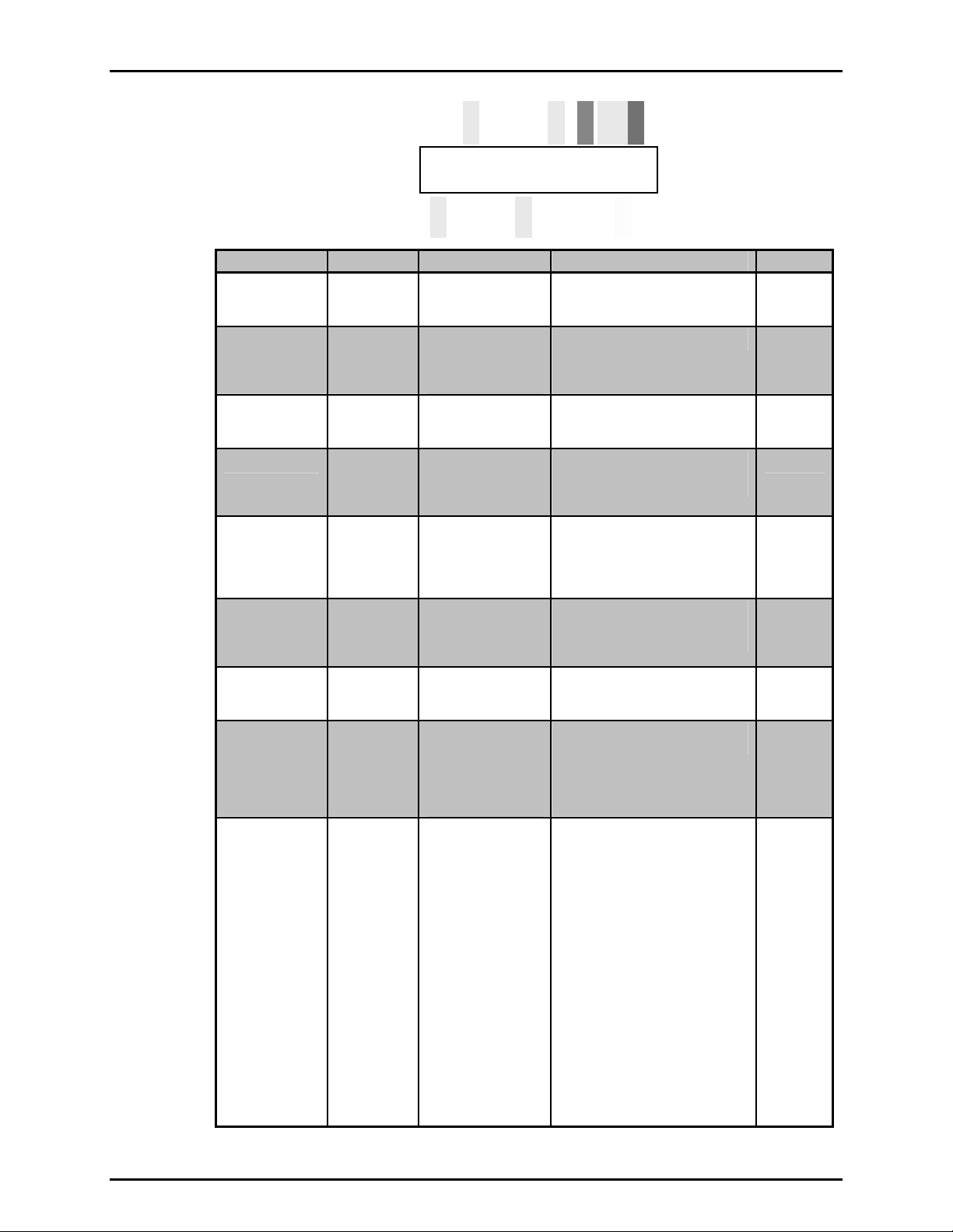
A new RPM4/HPMS A70M/A20M-AF includes all items listed in Table 1.
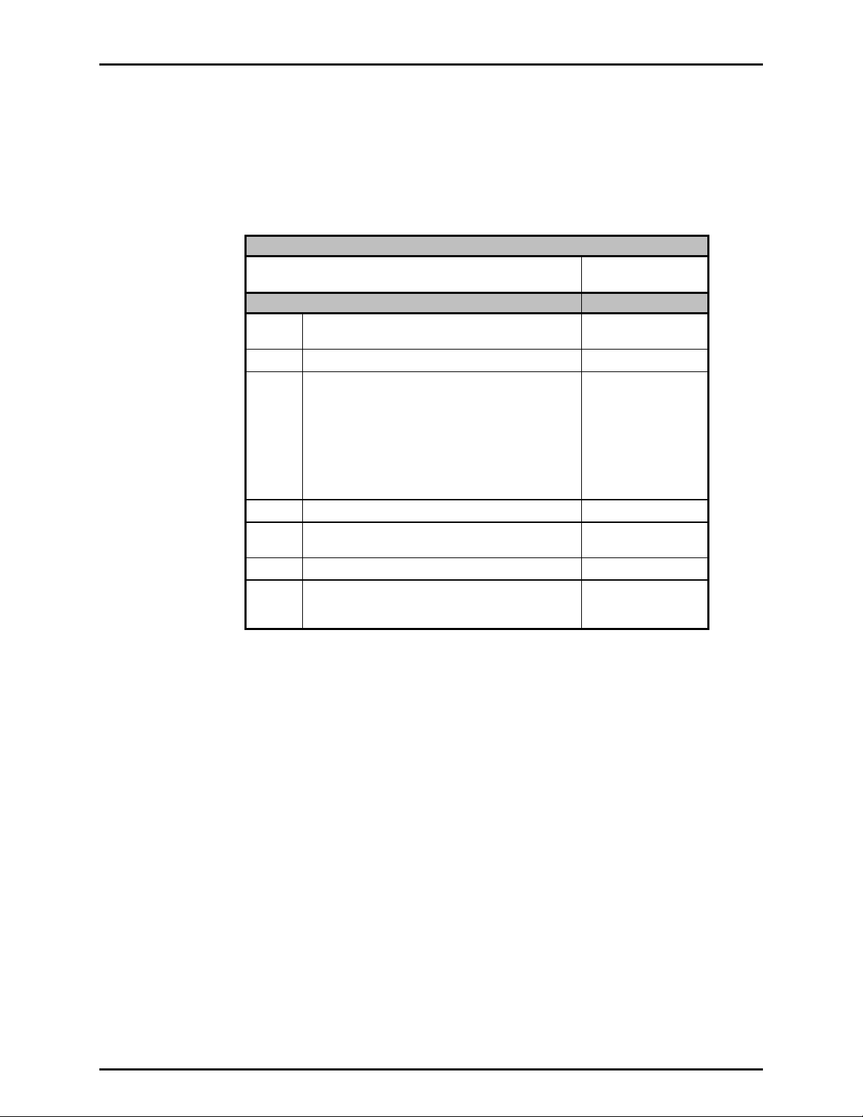
Table 1. RPM4/HPMS A70M/A20M-AF Parts List
DESCRIPTION PART NO.
RPM4/HPMS A70M/A20M-AF Reference Pressure
Monitor/High Pressure Mounting System
ACCESSORIES:
1 ea. Transport case (with inserts) (used for original
shipment)
1 ea. Foot switch assembly 401613
1 ea. PGC-10000-AF Documentation Disk including:
• RPM4/HPMS A70M/A20M-AF Operation and
Maintenance Manual, p/n 550136
• GPC1-10000-AF Operation and Maintenance
Manual, p/n 550135
• GB-152-AF Operation and Maintenance Manual,
p/n 550137
1 ea. Calibration Report 550100
1 ea. Test Report (PGC-10000-AF) (if the RPM4/HPMS is
delivered as part of an PGC-10000-AF system)
1 ea. Power cord (7.5 ft) 100770
1 ea. General Accessories Disk (white CD) (Important :
Includes system support software and
documentation)
402192
124198
402189
550138
102987
2.2 PGC-10000-AF SYSTEM
RPM4/HPMS A70M/A20M-AF is usually delivered as the reference pressure measurement component of
a PGC-10000-AF Pneumatic Gauge Calibrator. The PGC-10000-AF system includes:
• RPM4/HPMS A70M/A20M-AF: Reference pressure monitor and high pressure mounting system used
as the pressure measuring reference of the calibration system.
• GPC1-10000-AF: Gas pressure controller used to set and adjust high pressure gas in the calibration
system.
• GB-152-AF: Gas booster package used to supply gas pressure up to 10 000 psi (70 MPa) to the
GPC1-10000-AF pressure controller.
© 2007 DH Instruments, a Fluke Company Page 6
Page 17
2. INSTALLATION
Each of the three components of the PGC-10000-AF system has its own Operation and Maintenance
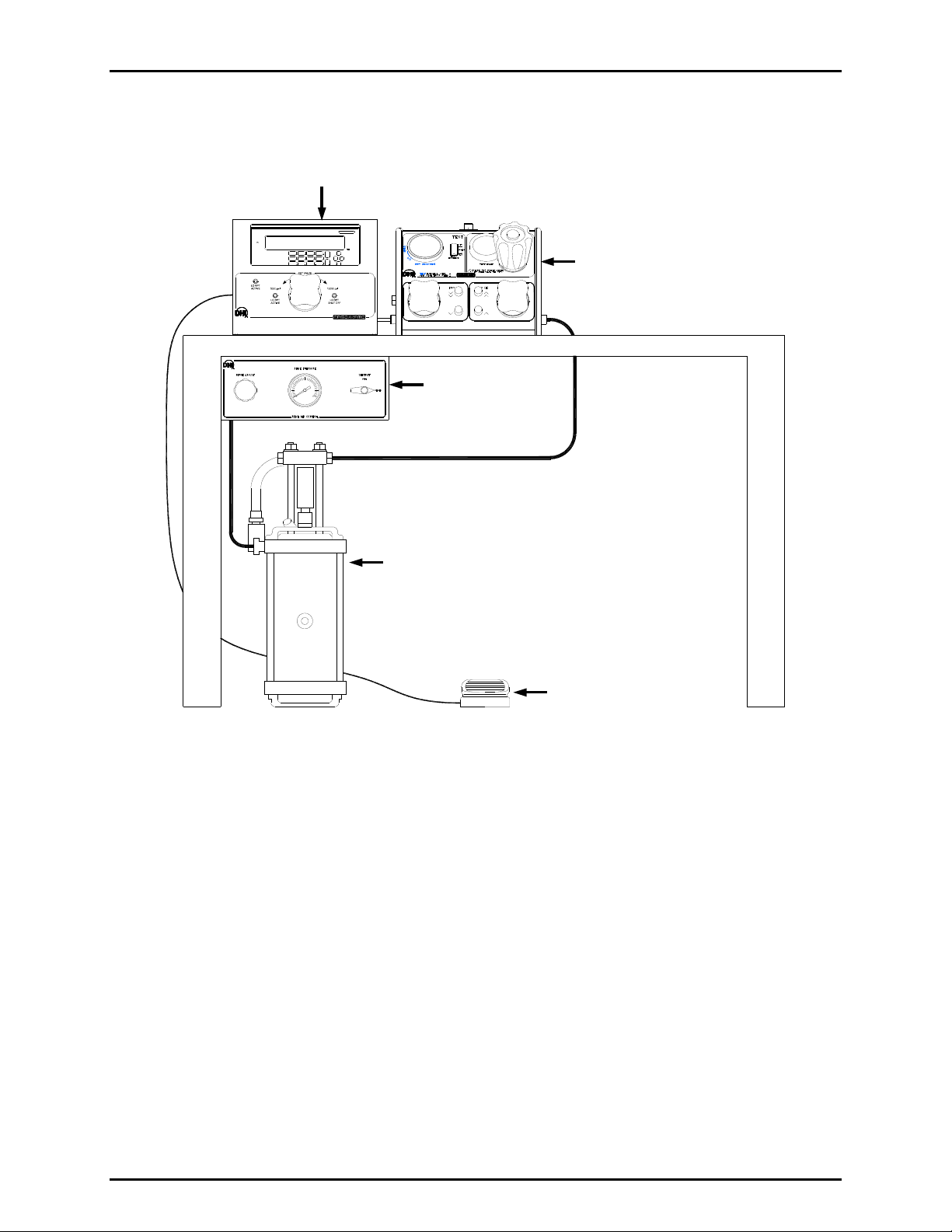
Manual and individual setup and start up instructions. Figure 1 shows the typical setup configuration of a
complete PGC-10000-AF system.
RPM4/HPMS A70M/A20M Reference Pressure Monitor
RPM4/HPMS A70M/A20M Reference Pressure Monitor
GPC1-10000-AF
CAUTION
CAUTION
CAUTION
CAUTION
GB152-AF
GB152-AF
GB152 Setting
GB152 Setting
Drive Air Control Kit
Drive Air Control Kit
GPC1-10000-AF
Gas Pressure Controller
Gas Pressure Controller
GB152 Pressure Generation Component
GB152-AF Gas
GB152 Pressure Generation Component
GB152-AF Gas
Booster
Booster
Remote ENTER Footswitch
Remote ENTER Footswitch
Figure 1. Typical PGC-10000-AF installation layout
2.3 SITE REQUIREMENTS
The RPM4/HPMS A70M/A20M-AF is usually delivered as part of an PGC-10000-AF pneumatic gauge
calibrator. The PGC-10000-AF also includes a GPC1-10000-AF and a GB-152-AF that each have their
own Operation and Maintenance Manual. See the GPC1 and GB-152 Operation and Maintenance
Manuals for information on their site requirements. Also see Section 2.2 for information on setup of a
complete PGC-10000-AF system.
Install RPM4 on a flat, stable surface at a convenient height. The front feet can be extended so that the
unit can be inclined for easier viewing. Consider the placement of the FOOT SWITCH which may need to
be accessed frequently while running calibrations.
Support facilities required for RPM4/HPMS A70M/A20M-AF include an electrical power source of 85 to
264 VAC, 47 to 440 Hz.
Page 7 © 2007 DH Instruments, a Fluke Company
Page 18
RPM4/HPMS A70M/A20M-AF OPERATION AND MAINTENANCE MANUAL
2.4 SETUP
2.4.1 PREPARING FOR OPERATION
To prepare RPM4 for check out and operation:
Remove the plastic plug from the RPM4/HPMS rear panel TEST connection.
Remove the protective plastic sheet from the front panel display.
Familiarize yourself briefly with the RPM4 and HPMS front and rear panels (see Sections
2.4.2, 2.4.3).
2.4.2 RPM4/HPMS FRONT, REAR AND SIDE VIEWS
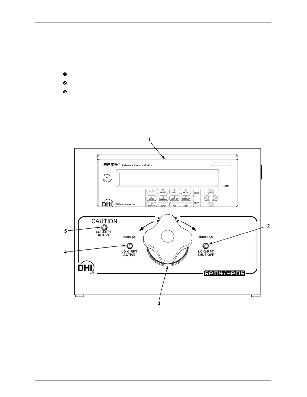
2.4.2.1 RPM4/HPMS FRONT VIEW
1. RPM4 A70M/A2 0M-AF Reference Pressure Monitor
2. Lo Q-RPT shut-off valve position LED
3. Lo Q-RPT shut-off valve
Figure 2. RPM4/HPMS front view
© 2007 DH Instruments, a Fluke Company Page 8
4. Lo Q-RPT active valve position LED
5. Lo Q-RPT active caution LED
Page 19

2. INSTALLATION
2.4.2.2 RPM4/HPMS REAR VIEW
1. Foot switch (remote [ENT])
cable connector
Figure 3. RPM4/HPMS rear view
2. TEST port (DH500 F)
Page 9 © 2007 DH Instruments, a Fluke Company
Page 20
RPM4/HPMS A70M/A20M-AF OPERATION AND MAINTENANCE MANUAL
2.4.2.3 RPM4/HPMS SIDE VIEW
1. Lo Q-RPT shut off valve
2. RPM4/HPMS A70M/A20M Reference
Pressure Monitor
3. Pressure relief valve (3 300 psi)
4. Foot switch (remote [ENT]) cable connector
5. TEST port (DH500 F)
Figure 4. RPM4/HPMS side view
2.4.3 RPM4 FRONT AND REAR PANELS
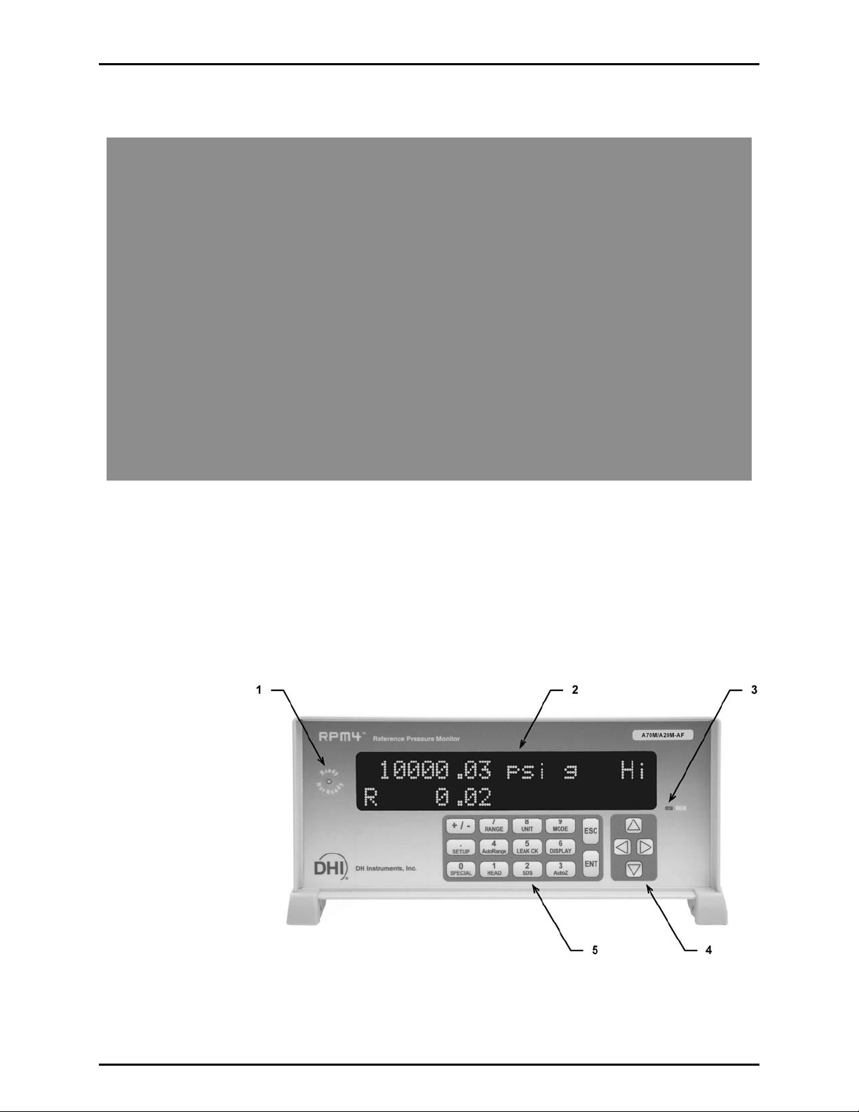
2.4.3.1 RPM4 FRONT PANEL
1. Ready/Not Ready indicator
2. Display
3. Remote activity indicator
Figure 5. RPM4 front panel
© 2007 DH Instruments, a Fluke Company Page 10
4. Cursor control keys
5. Multi-function keypad
Page 21
2. INSTALLATION
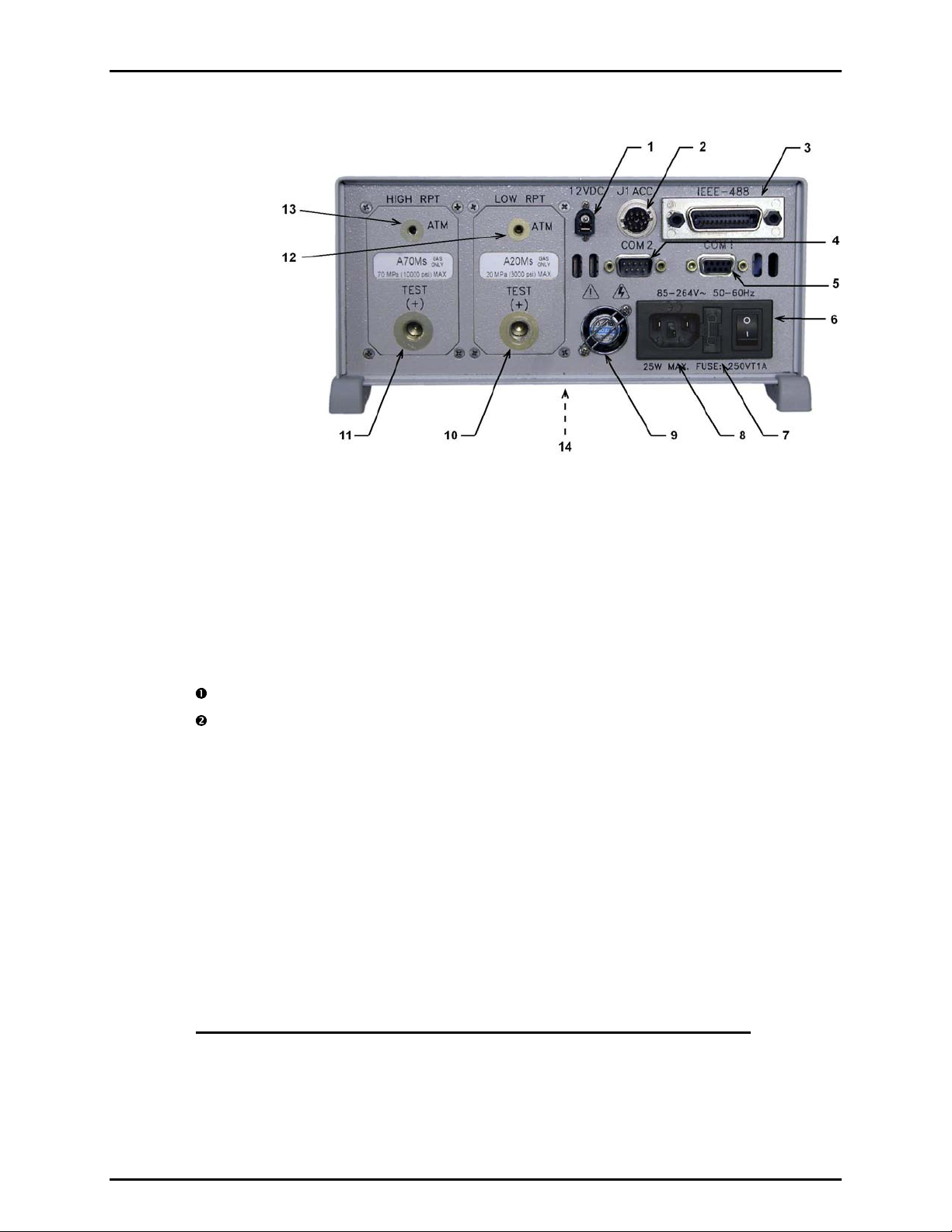
2.4.3.2 RPM4 REAR PANEL
1. 12VDC Power Supply Connection
2. Accessories connector (to HPMS rear
panel FOOTSWITCH and LEDs)
3. IEEE-488 Connector
4. COM2 Connector
5. COM1 Connector
6. Power Switch
7. Fuse
Figure 6. RPM4 rear panel
8. Electrical Power Connector
(IEC-320-C13)
9. Fan
10. TEST(+) Pressure Port, Lo Q-RPT
11. TEST(+) Pressure Port, Hi Q-RPT
12. ATM Pressure Port, Lo Q-RPT
13. ATM Pressure Port, Hi Q-RPT
14. Product Label (bottom of case)
2.4.4 POWER CONNECTION
Connect the supplied power cable to the RPM4 rear panel power module.
Connect the other end of the power cable to an electrical supply of 85 to 264 VAC,
50/60 Hz.
2.4.5 FOOTSWITCH CONNECTION
Connect the foot switch supplied in the RPM4/HPMS accessories to the HPMS rear panel
electrical connection labeled FOOT SWITCH. Place the foot switch on the floor at a convenient
location (see Section 2.2, Figure 1). The FOOT SWITCH function is equivalent to the RPM4 front
panel [ENT] key and may be used frequently while running tests and calibrations.
2.4.6 TEST PORT CONNECTION
A single high pressure TEST port is provided on the rear panel of the HPMS.
The test port connection is a DH500 F. DH500 is a gland and collar type fitting for 1/4 in.
(6 mm) coned and left hand threaded tube. DH500 is equivalent to AE F250C, HIP HF4, etc.
Connection to GPC1 if the RPM4/HPMS is Part of an PGC-10000-AF System
If the RPM4/HPMS was delivered as part of a PGC-10000-AF Pneumatic Gauge Calibrator, a
GPC1 Gas Pressure Controller was delivered with it. The GPC1 includes a fittings kit with
the necessary fittings to interconnect the RPM4/HPMS and GPC1 as well as instructions on
making the connection. See the GPC1-10000-AF manual.
Page 11 © 2007 DH Instruments, a Fluke Company
Page 22
RPM4/HPMS A70M/A20M-AF OPERATION AND MAINTENANCE MANUAL
USE THE CORRECT PRESSURE CONNECTORS: The RPM4/HPMS TEST port fitting is a
DH500 F (see Section 1.2.1). It is NOT a 1/8 in. NPT F. Never use a fitting other than the
corresponding male fitting in these connectors. Damage to the connectors and dangerous failure
under pressure could result from using incorrect fittings.
DO NOT APPLY PRESSURE UNTIL YOU ARE FAMILIAR WITH OPERATION: The RPM4/HPMS
rear panel test port connects internally to both the RPM4’s 3 000 psi (20 MPa) and 10 000 psi
(70 MPa) Q-RPTs. The valve on the front of the HPMS isolates the low pressure Q-RPT when the
high pressure Q-RPT is in use. Do not apply pressure to the RPM4/HPMS until you are familiar
with its operation and know how to protect the low pressure Q-RPT from overpressure (see
Section 3.2.5). FAILURE TO PROTECT THE LOW PRESSURE Q-RPT FROM OVERPRESSURE MAY
DESTROY IT. DAMAGE DUE TO Q-RPT OVERPRESSURE IS NOT COVERED BY THE PRODUCT
WARRANTY.
2.4.6.1 THE ATM PORTS OF RPM4
The ATM ports on the RPM4 Q-RPT modules are connected to the RPM4’s
internal barometer to assure that the RPM4 gauge pressure measurements are
relative to ambient pressure. These ports should always be left completely
unobstructed and open to atmosphere.
NEVER plug, obstruct or connect a supply pressure to the RPM4 Q-RPT module
ATM ports. This may adversely affect GAUGE mode operation and AutoZeroing
functions.
2.4.7 CHECK/SET SECURITY LEVEL
RPM4 has a security system based on user levels. By default, the security system is set to
“low”, which includes access restriction to internal calibration coefficients, and there is no
password required to change the security level. See Section 3.5.5.5 for information on the
security level system. As part of the RPM4 startup, determine the security level that is
appropriate for the RPM4 and set a password if desired.
RPM4 is delivered with the security level set to “low” to avoid inadvertent altering of critical
internal settings but with access to changing security levels unrestricted. It is recommended that the
low security level be maintained at all times and password protection be implemented if control
over setting of security levels is desired.
2.4.8 SETTING UP AUTOTEST FILES
RPM4 supports automated test/calibration sequences. AutoTest sequence
parameters for testing specific DUTs can be stored in File AutoTest files and
recalled to run a test. Consider setting up File AutoTest files for frequently tested
DUTs as part of the RPM4 set up process (see Section 3.3.10, 3.4.5.2).
© 2007 DH Instruments, a Fluke Company Page 12
Page 23

2. INSTALLATION
2.5 POWER-UP AND VERIFICATION
2.5.1 SWITCH POWER ON
Actuate the power switch on the RPM4 rear panel. Observe the front panel display as RPM4
initializes, error checks and goes to the MAIN RUN screen (see Section 3.1.1). If the RPM4
fails to reach the main run screen, service is required. Record the sequence of operations
and displays observed and contact a DHI Authorized Service Provider (see Section 8,
Table 23).
Check that one of the two green Valve Status LEDs on the front panel of the HPMS is lit (the
red LED should NOT be ON). If neither of the green LEDs on the HPMS front panel lights,
check that the 12 pin circular connector at the rear of the RPM4 itself is properly connected to
the ACC. J1 connector.
2.5.2 CHECK PRESSURE MEASUREMENT OPERATION
2.5.2.1 CHECKING ABSOLUTE MODE PRESSURE MEASUREMENT
Let the RPM4 warm up with power ON for approximately 30 minutes.
Press [MODE] on the RPM4 and select absolute. If desired, change the
pressure unit of measure using [UNIT] (see Section 3.3.2).
Open the RPM4/HPMS TEST port to atmosphere. Put the valve knob in the
HPMS front panel into the Lo Q-RPT Active position. This opens the Lo and Hi
Q-RPTs to the HPMS TEST port.
Use [RANGE] (see Section 3.3.1) to select the Lo Q-RPT. Observe the RPM4
indicated pressure. Check that the agreement of the RPM4 indicated value with
a calibrated barometer in the same room is ± 0.15 psi. The calibrated barometer
must have a measurement uncertainty of ± 0.25% of better.
Use [RANGE] to select the Hi Q-RPT Check that the agreement of the RPM4
indicated value with a calibrated barometer in the same room is ± 0.5 psi.
If a Q-RPT does not agree within tolerance, it may need to be AutoZeroed (see
Section 3.3.9), calibrated (see Section 5.3) or repaired.
2.5.2.2 CHECKING GAUGE MODE PRESSURE MEASUREMENT
Let the RPM4 warm up with power ON for at approximately 30 minutes.
Open the RPM4/HPMS TEST port to atmosphere. Put the valve knob in the
HPMS front panel into the Lo Q-RPT Active position. This opens the Lo and Hi
Q-RPTs to the HPMS TEST port.
Use [RANGE] (see Section 3.3.1) to select the Lo Q-RPT. Press [MODE] on the
RPM4 and select gauge. If desired, change the pressure unit of measure using
[UNIT] (see Section 3.3.3).
The value indicated should be near zero. Press [AutoZ]. This runs AutoZ to
zero the Q-RPT reading (see Section 3.3.9.1). Upon return to the main run
screen, observe that the indication of measured pressure has zeroed.
Use [RANGE] to select the Hi Q-RPT and repeat the zeroing process.
Page 13 © 2007 DH Instruments, a Fluke Company
If the display fails to zero properly for either Q-RPT, RPM4 may need repair.
Page 24

RPM4/HPMS A70M/A20M-AF OPERATION AND MAINTENANCE MANUAL
It is normal for RPM4 to indicate a value other than zero when vented when
gauge mode is first entered or ranges are changed, especially if AutoZ is OFF, RPM4
has been OFF for some time or its location has changed.
2.6 SHORT TERM STORAGE
The following is recommended for short term storage of RPM4/HPMS:
• Vent the RPM4/HPMS TEST port.
• Switch the RPM4 power OFF.
2.7 LONG TERM STORAGE AND/OR PREPARATION FOR SHIPPING
The following is recommended for long term storage and or shipping of RPM4/HPMS:
• Plug the HPMS TEST port.
• Place the RPM4/HPMS in a plastic bag.
• Place the RPM4/HPMS in the custom shipping/storage case in which it was delivered.
© 2007 DH Instruments, a Fluke Company Page 14
Page 25

3. OPERATION
.
33.
O
PPEERRAATTIIOON
O
N
3.1 USER INTERFACE
RPM4/HPMS is designed to offer the optimum balance between simple, straight forward operation and
the availability of a wide variety of functions with a high level of operator discretion if desired.
The local operator interface is through the RPM4 front panel 2 x 20 character alpha-numeric display, a
function/data keypad, a cursor control pad, an [ENTER] footswitch and a Ready/Not Ready indicator.
Remote communications are also available via RS-232 or IEEE-488 interfaces (see Section 4).
The HPMS mounts the RPM4 at a convenient viewing angle and includes a valve and visual indicators to
isolate and protect the RPM4’s 3 000 psi Q-RPT (A20M) when using the 10 000 psi Q-RPT (A70M) (see
Section 3.2.5).
3.1.1 MAIN RUN SCREEN
The RPM4 MAIN RUN screen is its home display that is reached on power-up and from which
other functions and menus are accessed. It is the very top level of all menu st ructures.
The MAIN RUN screen is where RPM4 is left in normal operation. It displays the current
measured pressure as well as a variety of additional information if desired.
Figure 7 and its legend summarize the RPM4 MAIN RUN screen fields and their function s.
RPM4 has a screen saver function which causes the display to dim if no key is pressed for
10 minutes. Pressing a key restores full power to the display. The screen saver time can be
changed or screen saving can be completely suppressed (see Section 3.5.5.1).
Page 15 © 2007 DH Instruments, a Fluke Company
Page 26
RPM4/HPMS A70M/A20M-AF OPERATION AND MAINTENANCE MANUAL
↑
PRESSURE1UNITM hzRR
DDISPLAYFUCNIONnn/nn
DISPLAY FIELD NAME PURPOSE CONTENTS SECTION
1. PRESSURE1 Measured
pressure
Displays pressure
measured by the
Numerical pressure value and
sign.
1.2.2.1,
3.3.1
active Q-RPT
2. UNIT Unit of
measure
Identifies unit of
measure in which
Pressure unit symbol 3.3.2
pressure values are
displayed
3. M Measurement
mode
Identifies
measurement mode
<a> absolute
<g> gauge
3.3.3
of displayed pressure
4. h Head
pressure
indicator
Indicates whether a
fluid head correction
is applied to
<h> the fluid head is not
zero
<blank> fluid head is zero
3.3.7
PRESSURE1
5. z AutoZero
indicator
Indicates whether
the AutoZero function
<z> AutoZ is ON
<blank> AutoZ is OFF
3.5.1,
3.3.9
is ON or OFF for the
active Q-RPT and
measurement mode
6. RR Active
Q-RPT
position
Indicates the position
of the active Q-RPT in
the RPM4
<Hi> Internal Hi
<Lo> Internal Lo
3.2.3
indicator
7. nn/nn Sequence
progress
indicator
8. DISPLAY
FUNCTION
Information
specific to
the DISPLAY
mode
Indicates progress of
an ATest sequence,
during test execution
Pressure indication
depending on current
RPM4 DISPLAY
function. Leading
<nn/nn> Number of this point
over total number of points
in the sequence
Numerical pressure value
and sign.
3.3.10
3.3.6
character identifies
the value
9. D Pressure
information
indicator
Pressure information
indicator depending
on current RPM4
DISPLAY function.
<σ> Display mode is
AVERAGE and value is
standard deviation
<R> Display mode is RATE
3.3.6
and value is pressure rate
of change per second
<H> Display mode is HI/LO and
value is high, then low
<D> Display mode is
DEVIATION and value is
difference from current target
<),
,↓ > Display mode is Q-
RPT and value is
measurement of inactive
Q-RPT
<F> Display mode is FREEZE
and value is last captured
reading
Blank, no character Current
display mode is CLEAN
Figure 7. MAIN RUN screen display fields
© 2007 DH Instruments, a Fluke Company Page 16
Page 27

3. OPERATION
3.1.2 FUNCTION / DATA KEYPAD LAYOUT AND PROTOCOL
The RPM4 has a function/data keypad for local operator access to direct
functions, function menus and for data entry.
1. The Function/Data keys allow very
commonly used functions to be accessed
directly by a single keystroke when pressed
from the MAIN RUN screen (see Section
3.1.1).
The name of the function is on the bottom
half of the key. These keys enter numerical
values when editing.
2. The Editing and Execution keys are for
starting and suspending command
execution, cursor control in menus and
editing entries.
3. The Menu/Data keys provide access to
function menus when pressed from the
MAIN RUN screen. The menu name is on
the bottom half of the key. The SETUP
menu is for more frequently used functions
(see Section 3.4). The SPECIAL menu is
for functions that are not generally used as
a part of day to day operation (see Section
3.5). These keys enter numerical values
when editing.
Figure 8. Keypad layout
Pressing the [ENT] key generally causes execution or forward movement in the
menu tree.
Pressing the [ESC] key moves back in the menu tree and/or causes execution to
cease or suspend. Pressing [ESC] repeatedly eventually returns to the MAIN RUN
screen and, from there, allows momentary viewing of the RPM4 introduction screen.
Pressing the [+/-] key changes a numerical sign when editing. It also toggles
through multiple screens when available and, from some run screens, is a
shortcut to a momentary display of active RANGE.
Pressing the [
], [ ], [ ] and [ ] keys allows up, down, reverse and
forward cursor movement when editing data entry or moving in menus.
Some screens go beyond the two lines provided by the display. This is
indicated by a flashing arrow in the second line of the display. Press the cursor
control keys to move the cursor to access the lines that are not visible or directly
enter the number of the hidden menu choice if you know it.
Page 17 © 2007 DH Instruments, a Fluke Company
Page 28

RPM4/HPMS A70M/A20M-AF OPERATION AND MAINTENANCE MANUAL
3.1.3 REMOTE [ENT] (ENTER) FOOTSWITCH
Operating the footswitch is the equivalent of pressing [ENT] on the front panel.
The remote ENTER feature can be particularly convenient when running AutoTests (see
Section 3.3.10) in which the operator’s hands are not free or attention is on the device under
test rather than the RPM4.
3.1.4 SOUNDS
RPM4 is equipped with a variable frequency tone device to provide audible feedback and
alarms. The beeper is used for the following indications.
Valid key press
Invalid key press
Change HPMS Lo Q-RPT
shut-off valve setting
Leak check completed
Upper or lower limit exceeded
Pmax! (overpressure limit)
exceeded
Hi Q-RPT is selected but Lo
Q-RPT is being pressurized
AutoTest in/out of tolerance
reading
Brief beep. Choice between three frequencies or NO
sound is available (see Section 3.5.5.2).
Descending two tone “blurp”.
Four one second beeps (see Section 3.2.5, 3.3.1).
Three two second beeps (see Section 3.3.5).
Intermittent one second beeps (see Section 3. 4.4).
Eight second high frequency beep (see Section 3.4.4.1).
Intermittent two second high frequency beep. The audible
alarm is combined with flashing of the red, Lo Q-RPT
Active LED on the HPMS (see Section 3.2.5, 3.3.1).
Ascending triad/descending triad ( see Section 3.3.10).
3.2 GENERAL OPERATING PRINCIPLES
3.2.1 PRESSURE READY/NOT READY
There is a Ready/Not Ready indicator LED on the RPM4 front panel. It is intended to provide
the user with a clear and objective indication of when a stable pressure has been achieved.
Ready is indicated when the current stability (rate of change) of pressure is less than the
stability limit. The user can set the stability limit (see Section 3.4.3) and the stability limit can
be set automatically by a AutoRange or AutoTest (see Section 3.3.4, 3.3.10). The Ready
indication is often used when comparing the RPM4 and a test device to indicate when a valid
reading can be made.
The Ready/Not Ready LED indications are:
<Green > Pressure Ready The pressure stability is within the stability limit.
<Red> Pressure Not Ready The pressure stability is NOT within the stability limit.
© 2007 DH Instruments, a Fluke Company Page 18
Page 29

3. OPERATION
3.2.2 GAUGE MODE, DYNAMIC COMPENSATION FOR ATMOSPHERIC PRESSURE
The RPM4 A70M/A20M-AF Q-RPTs are intrinsically absolute but they are also used for gauge
measurement mode (see Section 3.3.3, PR INCIPLE ). Gauge measurement mode is achieved by
subtracting the value of atmospheric pressure, P
using AutoZ (see Section 3.2.2). The AutoZ routine that measures P
[AutoZ] whenever RPM4 is in the vented condition. This assures the continuous updating of the
value corresponding to atmospheric pressure. Gauge pr e s s u r e is the mea sur ed ab solut e
P
offset,G
pressure, P
, minus the atmospheric offset, P
u
P
gauge
offset,G
= Pu - P
However, atmospheric pressure may change between opportunities to run AutoZ and update
the value of P
, for example when running an extended test without venting. RPM4 uses
offset,G
dynamic compensation for atmospheric pressure to correct for changes in atmospheric
pressure between opportunities to run AutoZ and update P
P
is determined, the reading of RPM4’s on board barometer, P
offset,G
Later, when no longer vented, the change in atmospheric pressure, ΔP
updated, is the difference between the current barometer reading, P
atm
atm,0
= P
:
atm
reading at the time of AutoZ execution, P
ΔP
Dynamic compensation for atmospheric pressure uses ΔP
thus always compensating real time for changes in atmospheric pressure:
, from the Q-RPT’s absolute reading
offset,G
, is run by pressing
offset,G
.
offset,G
. When AutoZ runs, and
offset,G
, is also recorded.
atm,0
, since P
atm
, and the barometer
atm
- P
atm,0
to correct the value of P
atm
offset,G
was
offset,G
,
P
gauge
= Pu - P
offset,G
- ΔP
atm
The additional uncertainty in gauge pressure mode due to the dynamic compensation for
atmospheric pressure technique is a function of the resolution and short term stability of the
on-board barometer, not its absolute measurement uncertainty. This additional uncertainty is
completely insignificant in the range of pressure covered by the RPM4 A70M/A20M-AF.
3.2.3 MULTIPE RANGES (Q-RPTS, AUTORANGE AND INFINITE RANGING)
RPM4 A 7 0 M/ A2 0 M- A F has two Quartz Reference Pressure Transducers (Q-RPTs). The A70M
(10 000 psi) Q-RPT is designated the Hi Q-RTP. The A20M (3 000 psi) Q-RPT is designated
the Lo Q-RTP. Which Q-RPT is currently active is continuously by characters in the upper
right hand corner of the MAIN RUN screen and most other screens.
Each RPM4 Q-RPT has a default range which is its maximum range. Additional ranges, lower
than the Q-RPT’s maximum, may also be created using AutoRange and AutoTest (see
Sect ion 3.3.4 , 3. 3.10). Ranges created using AutoRange are temporary but may be saved with
all their settings for reactiv ation (see Se ction 3. 4.1.1).
An RPM4 range is identified by a range screen showing the Q-RPT used by the range, its current unit
of measure and its full scale pressure in gauge an d absolute measurement modes. The range
screen is:
1. Q-RPT designator.
2. Type of range. DF for the Q-RPT’s default r ange; AR for a range
created by AutoRange.
3. Q-RPT position designator.
4. Current pressure unit of measure.
5. Full scale pressure in current unit of measure in gauge (<g>) and/or
absolute (<a>) measurement mode.
Active A70M DF Hi
psi 10000g/10000a
Page 19 © 2007 DH Instruments, a Fluke Company
Page 30
RPM4/HPMS A70M/A20M-AF OPERATION AND MAINTENANCE MANUAL
The ranges available on the RPM4 are accessed using [RANGE] (see Section 3.3.1) and/or
created using [AutoRange] (see Section 3.3.4).
Most settings made in an RPM4 range, such as unit of measure, measurement mode, display
resolution, and stability setting are specific to the range. Settings selected while one range is
active apply to that range and not to other ranges. The range specific settings are stored with
the range and recalled whenever the range is made active. This makes setting up ranges a
convenient way to store and recall frequently used operating configurations. See Table 2 f or a li sti ng
of RPM4 adjustments and settings and whether they are range, Q-RPT or system specific.
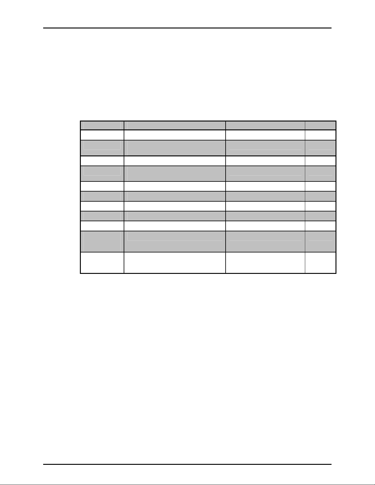
Table 2. Settings and what they are specific to
(range, measurement mode, Q-RPT, system)
SETTING PURPOSE SPECIFIC TO SECTION
[UNIT] Set pressure unit of measure Range 3.3.2
[MODE] Set pressure measurement mode
[DISPLAY] Set bottom line display function System 3.3.6
[HEAD] Set fluid head correction height, fluid, unit
[AutoZ] Run AutoZ Q-RPT and measurement mode 3.3.9
Resolution Set pressure display resolution Range 3.4.2
Stability Set Ready/Not Ready stability test. Range 3.4.3
Upper Limit (UL) Set upper limit alarm Range and measurement mode 3.4.4
AutoZ AutoZ, ON/OFF, set and view values Q-RPT and measurement mode 3.5.1
Screen Saver,
Sound, Time,
ID, Level
Cal Various Q-RPT and barometer calibration
(absolute, gauge)
of measure
Set system user preferences System 3.5.5
functions, including turning off absolute and
negative gauge modes
Range 3.3.3
System 3.3.7
Q-RPT or barometer 3.5.8
3.2.4 AUTOMATED TEST AND CALIBRATION SEQUENCES
The RPM4 AutoTest function supports “Quick” and “File” automated calibration sequences.
These automatically AutoRange the RPM4, setting its resolution, stability limit and upper limit
based on the characteristics of the device under test. They also prompt the user through the
increments of the calibration sequence and log calibration data. The AutoTest function
should be used for most common calibration tasks, especially calibration of analo g pressure
gauges (see Section 3.3.10).
3.2.5 HPMS (HIGH PRESSURE MOUNTING SYSTEM)
The HPMS (high pressure mounting system) holds the RPM4 at a convenient viewing angle
and includes a valve and visual indicators to isolate and protect the RPM4’s 2 000 psi (A20M)
Q-RPT when using the 10 000 psi (A70M) Q-RPT.
See Figure 10 for an HPMS schematic.
OPERATION
Numerical references in this Section refer to Figure 9.
In normal use, the operator’s only interaction with the HPMS is to operate the isolation valve
knob to connect and disconnect the Lo Q-RPT from the TEST port. The valve’s operation is
prompted by the Valve Position LEDs (2, 4).
© 2007 DH Instruments, a Fluke Company Page 20
Page 31

3. OPERATION
The Lo Q-RPT isolation valve (3) isolates and protects the Lo Q-RPT from the TEST port
when it is closed (knob fully CCW) and opens the Lo Q-RPT to the TEST port when it is open
(knob fully CW).
The Valve Position LEDs (2, 4) indicate the position in which the valve knob should be set
based on the current Q-RPT selection on the RPM4. If the Hi Q-RPT is selected, the LO Q-
RPT SHUT OFF LED (2) is lit indicating that the valve knob should be turned fully CW to
close the valve, protecting the Lo Q-RPT from high pressure. If the Lo Q-RPT is selected,
the LO Q-RPT ACTIVE LED (4) is lit indicating that the valve knob should be turned fully
CCW to open the valve, connecting the Lo Q-RPT to the test pressure.
The HPMS isolation valve (3) must always be in the closed position (knob fully CCW) when
operating at pressure greater than 3 000 psi (20 MPa).
The CAU TION LO Q-RPT ACTIVE LED (5) is used to indicate tha t the Lo Q-RPT is active and
provide an alert when the Lo Q-RPT is active but a Hi Q-RPT ra nge is selected on th e RPM4.
The CAUTION LO Q-RPT ACTIVE LED (5) is driven by the value of pressure current ly measured
by the Lo Q-RPT , it is not driven by the val ve positio n as the re is no se nsing of t he valve p osition.
The CAUTION LO Q-RPT ACTIVE LED (5) has three possible conditions:
• LED is OFF: The Lo Q-RPT is NOT active. The Lo Q-RPT is considered active when it
measures a pressure greater than about 30 psig (200 kPa).
• LED ON continuously: The Lo Q-RPT IS active and the Lo Q-RPT is selected on
the RPM4. The LED is lit as a reminder that the Lo Q-RPT is active and pressure over its
maximum working pressure of 3 000 psi (20 MPa) should not be applied.
• LED is flashing ON/OFF accompanied by high frequency beeps and <!!LO Q-RPT
ACTIVE!!> displayed by RPM4: Lo Q-RPT IS active and the Hi Q-RPT is selected on
RPM4. The Lo Q-RPT should NOT be exposed to pressure when the Hi Q-RPT is
selected. Exposing the Lo Q-RPT to pressures for which the Hi Q-RPT is normally used,
will overpressure and damage the Lo Q-RPT Vent pressure from the RPM4 and shut off
the Lo Q-RPT with the Lo Q-RPT shut off valve before continuing to use the Hi Q-RPT.
If the Hi RPT is selected with the Lo Q-RPT active, RPM4 goes into an alarm condition to avoid
accidental overpressure of the Lo Q-RPT while using a Hi Q-RPT. The pressure on the Lo Q-RPT must be
reduced to less than 30 psig (200 kPa) so that the CAUTION LO Q-RPT ACTIVE LED is OFF before
shutting the Lo Q-RPT shut off valve and selecting the Hi Q-RPT.
The HPMS pressure relief valve (Figure 10, Ref 3) is set to open at 110 % of the RPM4 Lo
Q-RPT maximum range. When the pressure applied to the Lo RPT reaches approximately
3 300 psi (23 MPa), the pressure relief valve will open exhausting gas to atmosphere and
reducing pressure. Prior to opening the pressure relief valve, the RPM4 will have gone into
an overpressure condition (see Section 3.4.4.1). If an overpressure condition occurs, reduce
pressure as soon as possible. The pressure relief valve will reseat automatically and close
when pressure is reduced.
Do NOT overpressure the Lo Q-RPT. The Lo Q-RPT may be damaged beyond repair by
pressure greater than 3 300 psi (23 MPa). Q-RPT damage from overpressure is logged in user
and factory maintenance pages and is not covered by the product warranty. The HPMS pressure
relief valve should only be considered a last resort means of protecting the Lo Q-RPT. Following
proper operating procedures, the Lo Q-RPT should never be overpressured.
Page 21 © 2007 DH Instruments, a Fluke Company
Page 32

RPM4/HPMS A70M/A20M-AF OPERATION AND MAINTENANCE MANUAL
1. RPM4 A70M/A2 0M-AF Reference Pressure Monitor
2. Lo Q-RPT shut-off valve position LED
3. Lo Q-RPT shut-off valve
Figure 9. RPM4/HPMS front view
4. Lo Q-RPT active valve position LED
5. Lo Q-RPT active caution LED
© 2007 DH Instruments, a Fluke Company Page 22
Page 33

3. OPERATION
1. HPMS TEST port (DH500 F)
2. Connection to R PM4 Lo Q-RPT (A20M)
(3 000 psi)
3. Lo Q-RPT pressure relief valve (3 300 psi)
5. RPM4 A70M/A2 0M-AF
Reference Pressure Monitor
6. Connection to RPM4 Hi Q-RPT
(A70M) (10 000 psi)
4. Lo Q-RPT shut off valve
Figure 10. HPMS pneumatic schematic
Page 23 © 2007 DH Instruments, a Fluke Company
Page 34

RPM4/HPMS A70M/A20M-AF OPERATION AND MAINTENANCE MANUAL
3.2.6 DIRECT FUNCTION KEYS SUMMARY
Table 3 provides a brief summary of RPM4 direct function key operation. It may be useful to
keep a copy of this summary near the RPM4/HPMS, especially when first becoming acquainted with its
operation.
Local operation of RPM4 is through the front panel keypad. To minimize multi-layered menu
structures, the keypad numerical keys also provide direct access to the most commonly used
functions. The function accessed is labeled on the bottom half of the key. Direct function
keys are active whenever RPM4 is in its MAIN RUN screen. Table 3 summarizes the
operation of the direct function keys.
Table 3. Summary of RPM4 function key operation
DIRECT FUNCTION KEYS ARE ACTIVE FROM THE MAIN RUN SCREEN
See corresponding manual Sections for full detail.
Adjust height of fluid head
correction. Set to zero to defeat
correction.
The SDS function is not used in
the A70M/A20M-AF configuration
of RPM4.
Run the AutoZ function to
AutoZero the active Q-RPT and
measurement mode.
Set up and optimize RPM4
features for a specific operating
range and measurement mode.
Run automated leak checking
routine.
View active range and toggle
through available ranges. [ENT] on
a range activates it.
Select pressure unit of measure for
the active range. Choice of units
available in this menu can be
customized.
Select the pressure measurement
mode for the active range (absolute,
or gauge).
Menu of less commonly used internal
functions and settings.
Menu of commonly used setup
features including save/delete
AutoRange ranges, set display
resolution, set stability limit, set
upper/lower, set up File AutoTest
sequences and view AutoTest data.
Select the display function for the
bottom line of the RPM4 display.
3.3 DIRECT FUNCTION KEYS
3.3.1 [RANGE]
PURPOSE
To view and/or change the active pressure measurement range and associated settings.
PRINCIPLE
An RPM4 range is defined as a pressure span and associated settings (see Sect ion 3.2.3).
An RPM4 may have multiple ranges. Each Q-RPT in the RPM4 system has a default range
which is its maximum span. The default ranges of the RPM4 A70M/A20M are 10 000 psi
(A70M) and 3 000 psi (A20M). Additional ranges, lower than the Q-RPT’s maximum span,
may also be created using AutoRange (see Section 3.3.4) or AutoTest (see Section 3.3.10).
© 2007 DH Instruments, a Fluke Company Page 24
Start or set functions such as Leak
Check, AutoTest and Freeze.
ENTER values when editing.
Page 35

3. OPERATION
Ranges created using AutoRange or AutoTest may be saved, with their settings, for
reactivation (see Section 3.4.1).
The [RANGE] function key allows the available RPM4 pressure ranges to be viewed and selected.
OPERATION
Pressing the [RANGE] function key activates the range viewing and selecting function. When
the [RANGE] function key is first pressed, the active range is displayed. For example:
1. Q-RPT designator.
2. Type of range. DF for the Q-RPT’s default range; AR for a range
created by AutoRange.
3. Q-RPT position designator.
4. Current pressure unit of measure.
5. Range’s full scale pressure in current unit of measure in gauge and/or
absolute measurement mode depending on type of Q-RPT and range .
Active A20M DF Lo
psi 3000g/3000a
Pressing the [+/-] key or the [RANGE] key again while in the RANGE functions toggles
through displays of the other available ranges, from lo west range to high est range.
To select a range to become the active range, press [ENT] while the range is displayed.
Any time a range change causes the active Q-RPT to change, the HPMS Lo Q-RPT
Isolation valve must be operated to connect or disconnect the Lo RPT from the TEST port.
The green Lo Q-RPT Valve Position LEDs indicate the correct position of the Lo Q-RPT
Valve Isolation Knob based on the RPM4 Q-RPT currently in use (see Section 3.2.5).
Pressing [ESC] while in the RANGE function returns to the MAIN RUN screen without
making a range change.
The HPMS Lo Q-RPT Isolation valve protects the Lo Q-RPT (3 000 psi max) from
overpressure when the Hi RPT is in use. Familiarize yourself with HPMS operation (see Section
3.2.5) before changing ranges and applying pressures. Always turn the Lo RPT Isolation Valve fully
in the direction of the lighted green LED before applying pressure.
Range full scale limits are given in the pressure unit that is currently active for that range.
Pressing [+/-] from the MAIN RUN screen provides a shortcut to a momentary view of the
active range.
Many RPM4 settings and functions are range specific. See Table 2 for identification of
range specific settings.
For best metrological performance, vent the RPM4 Q-RPT before changing ranges.
Page 25 © 2007 DH Instruments, a Fluke Company
Page 36

RPM4/HPMS A70M/A20M-AF OPERATION AND MAINTENANCE MANUAL
3.3.2 [UNIT]
PURPOSE
To select the measurement mode (absolute, gauge), use [MODE] (see Section 3.3.3).
To select the unit of measure in which RPM4 displays pressure values.
PRINCIPLE
RPM4 allows the unit of measure in which pressure values are displayed to be changed.
RPM4 A70M/A20M-AF supports 13 standard pressure units of measure as well as user
defined units. To simplify operation, quick access to six units is made available under the
[UNIT] key. The [UNIT] key contents can be customized by the user to any configuration of
six units (see Section 3.5.6).
Internally, RPM4 always operates in Pascal (Pa), the SI unit of pressure. Values of pressure
are represented in other units by the application of conversion factors to convert from Pa (see
Section 7.1.1).
OPERATION
To change the active pressure unit of measure for a
range, press [UNIT] from the MAIN RUN screen while
the range is active. The display is:
1psi 2MPa 3kPa
4bar
The cursor is on the number correspo nding to the active pre ssure unit of measure for t he active range.
To change the pressure unit of measure, select the desired unit. Making the selection returns
to the MAIN RUN screen with the selected unit active.
The pressure unit of measure selected is range specific. When in a given range, all functions
and settings are represented in the current measurement unit for that range. However, certain
internal and/or metrological functions (e.g., Q-RPT calibration coefficients) are always represented
in Pa regardless of the current range unit.
See Section 7.1.1 for tables of the conversion factors used by RPM4.
If the pressure unit selected is inWa (inches of water), the reference temperature for water
density must we specified in a separate menu (choices are 4ºC, 20ºC 60ºF). No reference
temperature selection is necessary for the unit mmWa as the only reference temperature
commonly used for mmWa is 4 ºC.
The choice of up to six units available under the UNIT function can be customized from a
wider selection by the user (see Section 3.5.6). The units available under the UNIT function can be
reset to default by reset (see Section 3.5.9.2).
© 2007 DH Instruments, a Fluke Company Page 26
Page 37

3. OPERATION
3.3.3 [MODE]
PURPOSE
To select the unit of measure, use [UNIT] (see Section 3.3.2).
To set the measurement mode (absolute, gauge) for the active range.
PRINCIPLE
RPM4 A70M/A20M-AF supports simple, one-step switching between two measurement
modes:
Absolute Measures pressure relative to vacuum (zero is hard vacuum). Range is
from zero absolute to full scale.
Gauge Measures pressure relative to atmosphere (zero is ambient pressure).
Range is from zero gauge to full scale, full scale must be greater than zero.
The RPM4 A70M/A20M-AF Q-RPTs measure pressure relative to a sealed vacuum reference
and are intrinsically absolute. Gauge mode is accomplished by offsetting of atmospheric
pressure with dynamic compensation for atmospheric pressure changes between offsets
using an on-board barometer (see Section 3.2.2). Access to absolute operation can be
turned OFF (see Section 5.3.5).
When changing modes for a range, if the full scale of the range is 100 psi (700 kPa) or greater,
the full scale is the same in both absolute and gauge modes. If the full scale is less than 100 psi,
the gauge mode full scale is 14.5 psi (100 kP a) lower than the absol ute mode full sca le.
Measurement mode selection is range specific.
OPERATION
To change the active measurement mode for a range,
press [MODE] from the MAIN RUN screen while the
range is active. The display is:
Measurement mode:
1absolute 2gauge
Select the desired measurement mode and operation returns to the main run screen with the
selected measurement mode active. If absolute measurement mode has been turned OFF in
calibration (see Section 5.3.5), absolute mode is not available.
Certain RPM4 settings, including AutoZ ON/OFF (see Section 3.5.1) are range AND
measurement mode specific. See Table 2 for a listing of settings and what they are specific to.
Absolute mode capability can be turned OFF in the calibration function (see Section 5.3.5).
When absolute mode is turned OFF, only gauge mode can be activated. <Gauge mode only, other
modes OFF> is displayed when [MODE] is pressed.
3.3.4 [AUTORANGE]
PURPOSE
To automatically set up RPM4 to optimize its measurement characteristics and features for a
specific, user defined pressure range of operation.
Page 27 © 2007 DH Instruments, a Fluke Company
Page 38

RPM4/HPMS A70M/A20M-AF OPERATION AND MAINTENANCE MANUAL
PRINCIPLE
RPM4 A70M/A20M-AF is designed to support the calibration and test of a very wide variety of
test ranges in absolute and gauge measurement modes.
The AutoRange function simplifies the task of selecting the Q-RPT best suited to cover a
specific test range and setting measurement parameters appropriately for that specific range.
These a re set automatically based on operator entry of desired measurement mode, pressure unit
of measure and range full scale. The selections and settings made by AutoRange are summarized
in Table 4.
A range set up using AutoRange and all its range specific settings, may be saved for recall
using [SETUP], <1range> (see Section 3.4.1). Saved ranges are available for later selection
using [RANGE] (see Section 3.3.1). If a range created by AutoRange is not saved, it is
overwritten by the next AutoRange or erased when another range is selected.
Press [ENT] from the main run screen in Rate DISPLAY mode to use the [AutoTest]
function to AutoRange RPM4 based on DUT tolerance (see Section 3.3.10).
Table 4. Settings made by AutoRange
SETTING/
SELECTION
Unit Set pressure unit of
Mode Set pressure
Full scale Establish span
Q-RPT Select most
Upper limit Set maximum pressure
Resolution Set display resolution 10 ppm of AutoRange
Stability Limit Set Ready/Not Ready
PURPOSE
measure
measurement mode
(absolute, gauge)
maximum
appropriate Q-RPT to
cover range and mode.
alarm limit.
stability criterion.
SETTING BY
[AUTORANGE]
Operator specified
during AutoRange
Operator specified
during AutoRange
Operator specified
during AutoRange
Q-PRT with lowe s t
default full scale that is
greater than the
AutoRange full scale
105 % of AutoRange
full scale pressure
span or
1 ppm of default QRPT span, whichever is
larger
50 ppm of AutoRange
span or 2 ppm of
default Q-RPT span,
whichever is larger
SETTING BY
[AUTOTEST[
(see Section 3.3.10)
Operator specified in
AutoTest definition
Operator specified in
AutoTest definition
Maximum pressure of
AutoTest definition
Q-PRT with lowe s t
default full scale that is
greater than the
maximum pressure of
AutoTest definition
105% of maximum
pressure of AutoTest
definition
10% of DUT tolerance
or
1 ppm of default QRPT span, whichever is
larger.
10% of DUT tolerance
or
2 ppm of default QRPT span, whichever is
larger
RELATED
SECTION
3.3.2
3.3.3
None
1.2.2.1
3.4.4
3.4.2
3.4.3,
3.2.1
© 2007 DH Instruments, a Fluke Company Page 28
Page 39
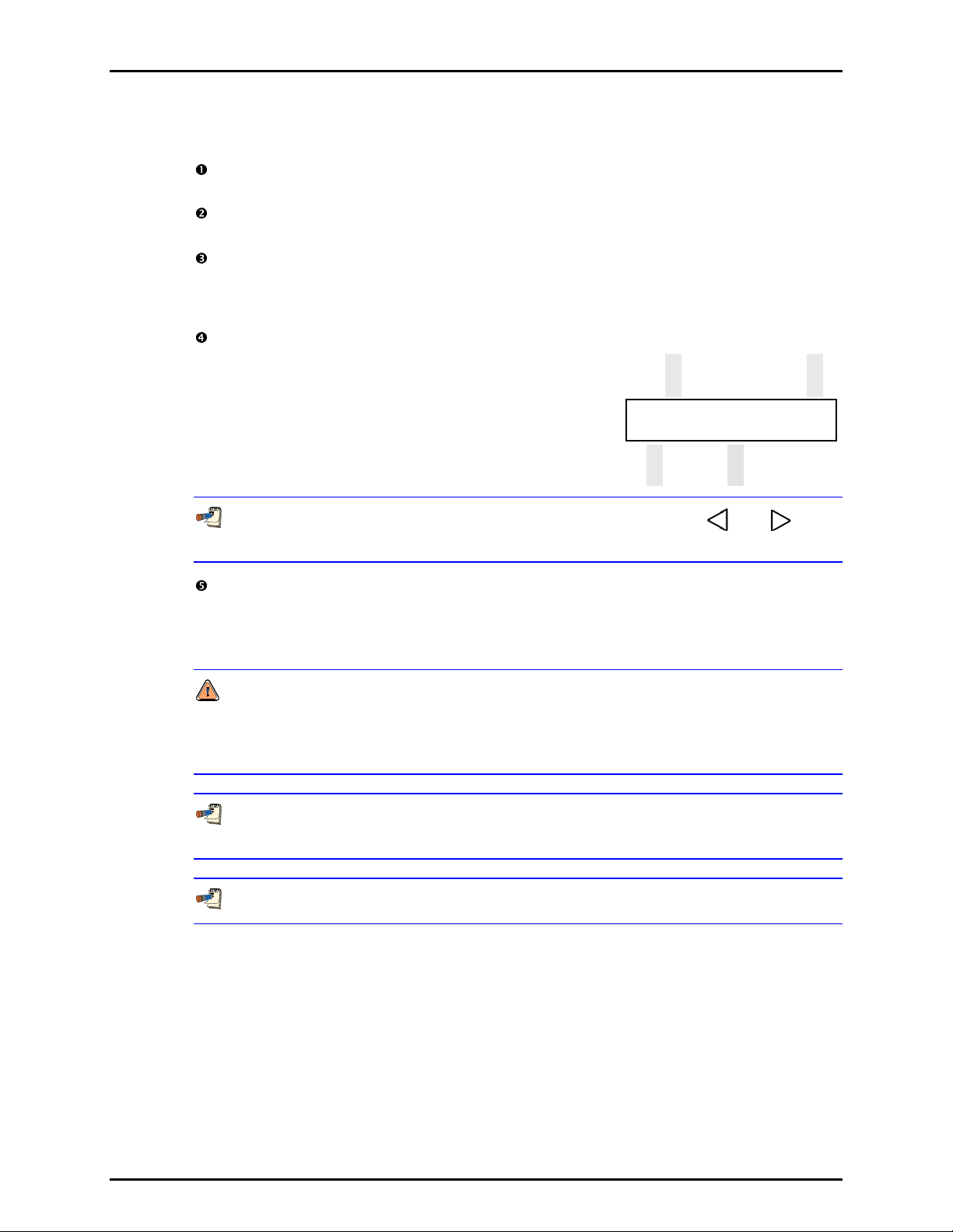
3. OPERATION
OPERATION
To use the AutoRange function, press [AutoRange] and respond to the RPM4’s prompt s.
Select AutoRange measurement mode: The screen is identical in appearance and
function to the [MODE] screen (see Section 3.3.3).
Select pressure unit of measure: The screen is identical in appearance and function
to the [UNIT] screen (see Section 3.3.2).
Enter the AutoRange full scale pressure: Enter the full scale pressure value in the
<------> entry field and press [ENT]. If the full scale value entered cannot be covered by
RPM4, an error message appears. If the full scale value can be covered, AutoRange
proceeds to the range display.
View proposed AutoRange range: The proposed AutoRange range screen is:
1. Indication that this is a screen of the proposed AutoRange range.
2. Designator and position of the Q-RPT that AutoRange has selected
to cover the AutoRange full scale and measurement mode.
3. Pressure unit of measure specified in AutoRange.
4. AutoRange full scale pressure in gauge mode and absolute.
AutoRange A70M Hi
psi 5000g/5000a
If AutoRange selects a Q-RPT but you would like to use the other one, the [ ] and [ ] cursor
control keys may be used to toggle between Q-RPTs so that the other can be selected.
Accept proposed AutoRange: To accept the proposed AutoRange and go to the MAIN
RUN screen with the new AutoRange range active, press [ENT] or [AutoRange]. To
modify the AutoRange full scale, measurement mode or pressure unit of measure, use
[ESC] to back through the AutoRange screens and make changes.
The HPMS Lo Q-RPT Isolation Valve protects the Lo Q-RPT (3 000 psi max) from
overpressure when the Hi Q-RPT is in use. Familiarize yourself with HPMS operation (see Section
3.2.5) before changing ranges and applying pressures. Always turn the Lo Q-RPT Isolation Valve
fully in the direction of the lighted green LED before applying pressure.
To verify or confirm the range from the MAIN RUN screen, use [+/-] or [RANGE] to view the
active range (see Section 3.3.1).
See Table 4 for a listing of all selections and settings affected by AutoRange and their values.
3.3.5 [LEAK CK]
PURPOSE
To run an automated leak check routine that determines the leak rate of the system
connected to the RPM4/HPMS TEST port.
PRINCIPLE
The LEAK CHECK function is provided as a means of checking and quantifying the leaks that
may be present in the system connected to the RPM4/HPMS TEST port.
Page 29 © 2007 DH Instruments, a Fluke Company
Page 40

RPM4/HPMS A70M/A20M-AF OPERATION AND MAINTENANCE MANUAL
The principle of the LEAK CHECK function is the measurement of the natural decrease or
increase of pressure in a fixed volume over time. The LEAK CHECK function allows a leak
check time to be set. The total pressure change and the average rate of change over the
leak check time are calculated and displayed.
OPERATION
Changing the pressure in a test system causes adiabatic temperature changes in the
pressurized medium that need to have dissipated before a valid leak measurement can be made.
In general, a 0.5 to 1 minute wait before running a leak check is adequate to allow the adiabatic
temperature change to dissipate and valid leak measurements to be made. However, stabilization
time may be much longer for large pressure changes and as volume and pressure increases.
To run a leak check, first set the pressure to the desired leak check pressure.
To access the LEAK CHECK function, press [LEAK CHECK] from the MAIN RUN screen.
Select <1run> to run a leak test. The display is:
Set leak check time:
1. Edit field for the time over which the leak rate will be
determined, in seconds.
15 s
Edit the leak check time if desired (minimum 1, maximum 999 seconds) and press [ENT].
Press [ENT] again when ready to start the leak test. The leak test display is:
1. Standard MAIN RUN screen first line showing measured
pressure.
2. Active Q-RPT position indicator
3. Indication that leak test is running and countdown of time
remaining.
4566.8 psi g Hi
Leak testing 13 s
[ESC] can be used to abort the running leak test. [ENT] while the leak test is running restarts
the leak check timer. When the leak check timer countdown has completed,
RPM4 beeps three times and the leak check results screen is displayed:
1. Total pressure change from start to finish of leak check time.
2. Indicator of Q-RPT used to run the leak check.
3. Average rate of change of pressure over the leak check
time period (∆P/time in seconds).
∆P - 0.12 psi g Hi
Rate 0.008 psi/sec
From the leak check results screen, press [ENT] to repeat the leak test.
Press [ESC] to return to leak check main menu and exit to the MAIN RUN screen.
To view the results of the most recently completed leak check, press <2view>. If NO leak
check data is stored (i.e., if the RPM4 has never run a leak test or a reset has cleared
previous leak test results), the results screen displays <Data NOT available> briefly and
returns to MAIN RUN screen. Press [ENT] or [ESC] to return to the MAIN RUN screen.
© 2007 DH Instruments, a Fluke Company Page 30
Page 41

3. OPERATION
Leak check is range specific in the sense that a leak check is run using the active range.
However, only one set of leak check results is maintained in memory and each leak test completed
overwrites the memory. View leak check always shows the results of the last leak check run
regardless of the range that is now active. The results screen includes the range indicator to
indicate the range in which the leak check was run.
3.3.6 [DISPLAY]
PURPOSE
To select, from a variety of choices, the information that is displayed on the second line of the
RPM4 display.
PRINCIPLE
RPM4 supports a variety of advanced pressure measurement functions that are displayed on
the second (bottom) line of the RPM4 display. In summary, the available display functions
included are:
AVERAGE Calculates the average measured pressure over a user specified period of
time and displays the average, the standard deviation about the mean and a
countdown in seconds to the next average (see Section 3.3.6.1). This function is
often used to filter out pressure noise in an unstable system. The magnitude of
the noise is quantified by the standard deviation about the mean. A second Avg
screen allows the instantaneous pressure values to be viewed during an
averaging cycle.
RATE Calculates and displays the current rate of change of pressure in current
pressure units/second (see Section 3.3.6.2). This function is a useful
indication of the stability of the pressure being measured. It is often used as
an indication of positive or negative leak rate and as a go/no go criterion of
when to take data when comparing RPM4 and a device under test, for
example in a calibration. Rate is used by the Ready/Not Ready function to
determine when a Ready condition exists (see Section 3.2.1).
DEVIATION Continuously calculates and displays the difference between the pressure
measured by RPM4 and a target pressure entered by the user (see Section
3.3.6.3). This function is useful in monitoring the evolution of pressure around
and/or away from a desired set point.
RPT Allows pressure measurement from the RPM4’s two Q-RPTs to be displayed
simultaneously (see Section 3.3.6.4).
HI/LO Records and displays maximum and minimum pressures measured (see
Section 3.3.6.5). This function is used to keep track of the minimum and
maximum pressure observed in a system over a period of time or to monitor
if a pressure min/max limit has been exceeded..
FREEZE Captures and displays the pressure measured by the active range of RPM4
when the [ENT] key is pressed (see Section 3.3.6.6). This function is useful
to record the pressure present at the time of an operator observed trigger
event, for example when the needle of an analog gauge is on the nominal
point or when a switch activates.
CLEAN Blanks out the second line of the display (see Section 3.3.6.7). This function
is used when a simple display of pressure measured by the RPM4 active
range with minimal additional information is desired.
Page 31 © 2007 DH Instruments, a Fluke Company
Page 42
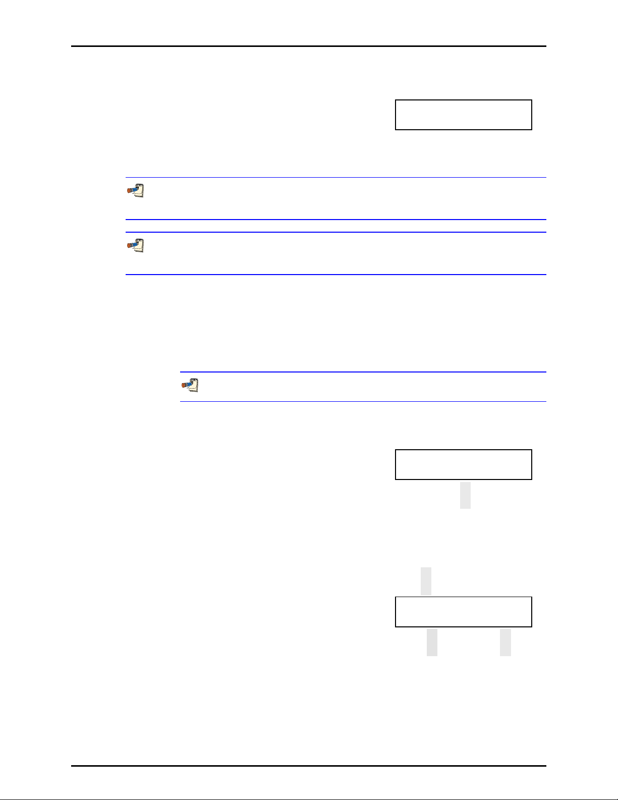
RPM4/HPMS A70M/A20M-AF OPERATION AND MAINTENANCE MANUAL
OPERATION
To set the DISPLAY function press [DISPLAY] from the main run screen.
The display is:
The cursor is on the active DISPLAY function. Selecting a DISPLAY function returns to the
main run screen with the selected function active. See Sections 3.3.6.1 to 3.3.6.7 for
information on each of the DISPLAY choices.
The DISPLAY selection is NOT range specific. A DISPLAY selection made in one range
applies to all ranges.
The default DISPLAY function is Rate which causes the second line of the display to show “R”
followed by the current rate of change of pressure in current pressure units per second.
3.3.6.1 AVG (AVERAGE)
1avg 2rate 3dev 4RPT
5HiLo 6freeze 7clean
PURPOSE
To activate the Average DISPLAY and/or adjust the period of time over which
averaging occurs.
See Section 3.3.6. Principle.
OPERATION
To access the Average DISPLAY, press [DISPLAY], <1Avg>. The display is:
Averaging Period:
1. Edit field for averaging period in seconds.
Default is 20. Minimum 1, maximum 999.
20 s
Edit the averaging time period if desired. Press [ENT] to return to the main run
screen with the Average DISPLAY active.
With the Average DISPLAY active the main run screen is:
1. Average measured pressure over last
completed averaging period.
2. Standard deviation in active pressure unit of
measure of last completed averaging period.
3. Countdo wn in seconds until completion of ongoing averaging period.
3001.57 psi a Hi
δ 0.03 18Avg
© 2007 DH Instruments, a Fluke Company Page 32
Page 43
3. OPERATION
The Average DISPLAY has a second screen that allows the instantaneous
pressure readings to be viewed while an averaging cycle is running.
The instantaneous Average screen is:
1. Instantaneous pressure values at RPM4’s
normal update rate.
2. Current rate of change of pressure in active
pressure unit/second.
3. Countdo wn in seconds until completion of ongoing averaging period.
3001.51 psi a Hi
R 0.01 18Avg
The [+/-] key toggles between the main run Average screen and the
instantaneous values Average screen.
Pressing [ENT] while in the Average DISPLAY aborts the current averaging
period and causes a new one to begin. [ENT] can thus be use to trigger a new
averaging period on demand.
In the Average DISPLAY the Ready/Not Ready indication applies to the result
of the previous averaging period (see Section 3.2.1). Ready indicates that all
readings during the previous averaging period met the stability criterion. Not Ready
indicates that one or more readings were outside of the stability criterion.
Changing the pressure unit of measure, measurement mode or range while the
averaging screen is active, starts a new averaging period.
To go to a DISPLAY other than Average, press [DISPLAY] and make a new
DISPLAY choice (see Section 3.3.6).
3.3.6.2 Rate
PURPOSE
To activate the Rate DISPLAY.
See Section 3.3.6, Principle.
The AutoTest function (see Section 3.3.10) to AutoRange RPM4 based on DUT
characteristics and run an automated test sequence is accessed by pressing [ENT]
from the Rate run screen.
Page 33 © 2007 DH Instruments, a Fluke Company
Page 44

RPM4/HPMS A70M/A20M-AF OPERATION AND MAINTENANCE MANUAL
OPERATION
To activate the Rate DISPLAY press [DISPLAY], <2Rate>. Pressing <2Rate>
returns to the main run screen with the Rate DISPLAY active.
With the Rate DISPLAY active the main run screen is:
1. Current rate of change of pressure in current
pressure unit per second.
8455.25 psi a Hi
R 0.03/sec
The Rate DISPLAY is different and separate from the stability setting which is
used to set the stability criterion on which the Ready/Not Ready indication is based
(see Sections 3.4.3 and 3.2.1). The Rate DISPLAY only causes the current rate of
change to be displayed and has NO affect on the stability setting or the Ready/Not
Ready condition.
The Rate DISPLAY is the default RPM4 main run screen display.
To go to a DISPLAY other than Rate, press [DISPLAY] and make a new
DISPLAY choice (see Section 3.3.6).
3.3.6.3 Dev (Deviation)
PURPOSE
To activate the Deviation DISPLAY and/or set the deviation target value.
See Section 3.3.6, Principle.
OPERATION
To activate the Deviation DISPLAY press
[DISPLAY], <3Dev>. The display is:
Edit the desired target value. Pressing [ENT] returns to the main run screen with
the Deviation DISPLAY active using the entered target value.
The target value is the value from which deviations (D) are measured by the
Deviation DISPLAY following:
D = current pressure - target pressure
© 2007 DH Instruments, a Fluke Company Page 34
Target:
9000.0 psi a
Page 45

3. OPERATION
With the Deviation DISPLAY active the main run screen is:
1. Deviation of current pressure from the target
value.
2. Target value.
D -1.8 T9000.0
Pressing [ENT] from the main run screen when the Deviation DISPLAY is active
goes directly to the Target editing screen. This allows the target value to be changed
and without going through the DISPLAY menu.
8998.2 psi a zH3
If the pressure measurement unit or mode is changed while the Deviation
DISPLAY is active the target value remains at the same numerical value. It is NOT
converted.
To go to a DISPLAY other than Deviation, press [DISPLAY] and make a new
DISPLAY choice (see Section 3.3.6).
3.3.6.4 RPT
PURPOSE
To activate the RPT DISPLAY.
See Section 3.3.6, Principle.
OPERATION
For the sake of clarity, when describing the RPT DISPLAY, the Q-RPT displayed on
the top line of the display when the RPT function is selected is referred to as the “active”
Q-RPT. The other Q-RPT to be displayed on the second (bottom) line of the RPM4 display
is referred to as the “inactive” Q-RPT. It is “inactive” in the sense that all RPM4 functions
and settings such as UNIT and RES still apply to the “active” Q-RPT. To make changes to
the “inactive” Q-RPT, for example to change its pressure measurement unit, it must be
made the active Q-RPT by a conventional range change (see Section 3.3.1).
To activate the RPT DISPLAY, press [DISPLAY], <4RPT>. Operation returns to
the MAIN RUN screen with the inactive Q-RPT displayed on the display’s bottom
line. The range of the inactive Q-RPT is always the default range, not an
AutoRanged range (see Section 3.2.3).
Page 35 © 2007 DH Instruments, a Fluke Company
Page 46

RPM4/HPMS A70M/A20M-AF OPERATION AND MAINTENANCE MANUAL
With the RPT DISPLAY active the main run screen is:
1. Active Q-RPT display.
2. Inactive Q-RPT display with Ready/Not Ready
indicator on far left (<*> indicates Ready).
2010.66 psi a zHi
*14.27 psi g zLo
When the RPT display is active, executing a range change to a range on the
inactive Q-RPT makes the inactive Q-RPT the active Q-RPT. The DISPLAY defaults
back to Rate ( Section 3.3.6.2).
To go to a DISPLAY other than RPT , press [DISPLAY] and make a new DISPLAY
choice (see Section 3.3.6).
3.3.6.5 Hi/Lo
PURPOSE
To activate the Hi/Lo DISPLAY.
See Section 3.3.6, Principle..
OPERATION
To activate the Hi/Lo DISPLAY press [DISPLAY], <5Hi/ Lo>. Pressing <5Hi/Lo>
resets the Hi/Lo values and returns to the main run screen with the Hi/Lo
DISPLAY active.
With the Hi/Lo DISPLAY active the main run screen is:
9989.2 psi a zHi
1. Highest pressure observed since Hi/Lo reset.
2. Lowest pressure observed since Hi/Lo reset.
H 9991.5 L 9987.3
The Hi/Lo values change each time a new Hi or Lo pressure is observed.
The Hi/Lo record can be reset at any time by pressing [ENT]. This allows a
Hi/Lo reset without going back through the DISPLAY menu.
If the pressure measurement unit, mode or range is changed while the Hi/Lo
DISPLAY is active, Hi/Lo resets.
To go to a DISPLAY other than Hi/Lo, press [DISPLAY] and make a new
DISPLAY choice (see Section 3.3.6).
© 2007 DH Instruments, a Fluke Company Page 36
Page 47

3. OPERATION
3.3.6.6 Freeze
PURPOSE
See Section 3.3.6, Principle.
To activate the Freeze DISPLAY.
OPERATION
To activate the Freeze DISPLAY press [DISPLAY], <6Freeze>. Pressing
<6Freeze> returns to the main run screen with the Freeze DISPLAY active.
With the Freeze DISPLAY active the main run screen is:
1. Pressure measured by active range of RPM4
when [ENT] was pressed (displays 0.00 by
default when Freeze DISPLAY is first
activated).
4435.6 psi a zHi
F 4420.7
Pressing [ENT] causes the current pressure measured by the active RPM4 Q-RPT
to be captured and displayed.
If the pressure measurement unit, mode or range is changed while the Freeze
DISPLAY is active, the Freeze value defaults back to zero.
To go to a DISPLAY other than Freeze, press [DISPLAY] and make a new
DISPLAY choice (see Section 3.3.6).
3.3.6.7 Clean
PURPOSE
To activate the Clean DISPLAY.
See Section 3.3.6, Principle..
OPERATION
To activate the Clean DISPLAY press [DISPLAY], <7Clean>. Pressing <7Clean>
returns to the main run screen with the Clean DISPLAY active.
With the Clean DISPLAY active the main run screen is:
1. Conventional main run screen first line.
2. “Clean” second line.
99.76 psi a zHi
To go to a DISPLAY other than Clean, press [DISPLAY] and make a new
DISPLAY choice (see Section 3.3.6).
Page 37 © 2007 DH Instruments, a Fluke Company
Page 48
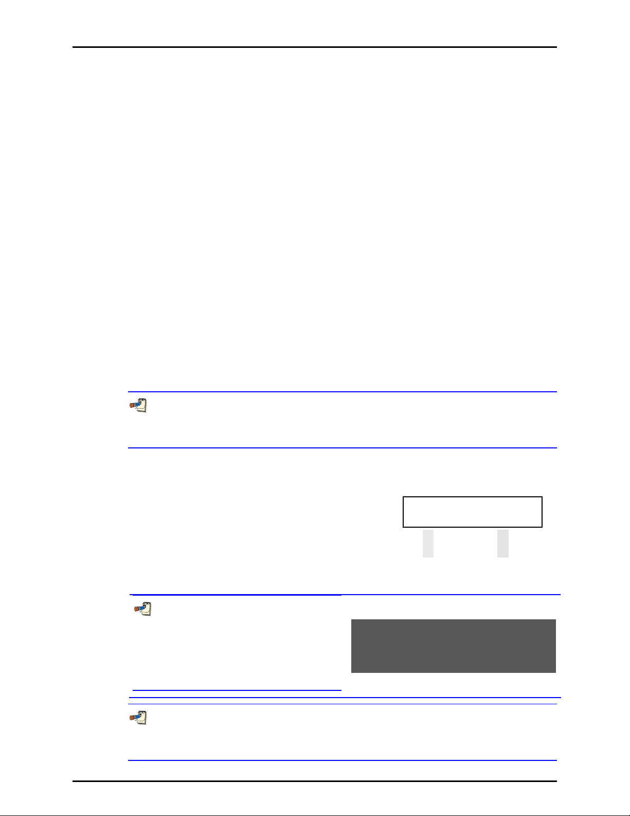
RPM4/HPMS A70M/A20M-AF OPERATION AND MAINTENANCE MANUAL
3.3.7 [HEAD]
PURPOSE
To cause a pressure fluid head correction to be added to or subtracted from the pressure
measured by the RPM4 reference pressure transducer in order to predict the pressure at a
height other than the RPM4/HPMS’s reference level.
PRINCIPLE
RPM4/HPMS measures gauge or absolute pressure at the height of the rear panel TEST port.
Frequently, when performing a calibra tion or tes t, the de vice or system under test is at a diffe rent
height than the RPM4/HPMS’s TEST port. This difference in height, frequently called head, can
cause a significant difference between the pressure measured by the RPM4/HPMS at its TEST
port height and the pressure actually appl ied t o the devi ce under te st whic h is at a d ifferent heig ht.
In this case, it is useful to make a head correction to the pressure measured by the RPM4 in order
to predict the pressure actually applied at a different hei ght.
RPM4 can accurately determine “head” pressures for gases (nitrogen, helium and air) and
liquids (oil, water) as the pressurized medium. In calculating the head value, standard gravity
(9.80665 m/s
density correcting for temperature of 20°C and the measured pressure using the gas’s
compressibility factor to 100 MPa (15 000 psi) and extrapolated above 100 MPa. Oil density
is taken to be 850 kg/m
to be 998.2321kg/m
2
) is used. Gas densities are calculated from the selected gas’s standard
3
, the density of typical calibration oils at 20°C. Water density is taken
3
(20°C). A custom liquid density may also be specified.
The [HEAD] function key is used to specify the height difference between the RPM4/HPMS
TEST port and another height. Entering a height of zero turns the function off. The height
units and the test medium can be changed using [SPECIAL], <3Head> (see Section 3.5.3).
As a general rule with RPM4 A20M/A70M-AF, use of the HEAD function to assure in
tolerance measurements with RPM4 A70M/A20M-AF is necessary only when the head exceeds 10
in. (25 cm) if the medium is a gas.
OPERATION
To access the HEAD function, press [HEAD]. The display is:
Edit head height:
1. Edit field for head height.
2. Test gas currently specified for the head correction.
+ 8 in N2
Edit the head height to the desired value. Press [ENT] to return to the MAIN RUN screen
with the new head correction active. Press [ESC] to return with no changes.
The reference height of the RPM4
pressure measurement is the middle of the
RPM4 TEST port. The head height should be
entered as a positive value if the device or
system under test is higher than the RPM4
and negative if it is lower.
The HEAD function is NOT range specific. The HEAD ON or OFF status remains the same
as Q-RPTs and ranges are changed. Edits made to the head settings are independent of active
range or Q-RPT.
© 2007 DH Instruments, a Fluke Company Page 38
Page 49

3. OPERATION
When a head correction is being applied, it is indicated by <h> in the fourth character from
the right in the top line of the MAIN RUN screen (see Section 3.1.1). When the head correction is
zero, the <h> is not shown.
The default head height unit is inches and the fluid species is Nitrogen (N2).To change units
of head height between inches and centimeters and to change the test fluid species, use
[SPECIAL], <3head> (see Section 3.5.3).
3.3.8 [SDS]
PURPOSE
The SDS function is not used in RPM4 A70M/A20M-AF.
3.3.9 [AUTOZ]
PURPOSE
See Section 3.5.1, Principle for a full explanation of the AutoZ function.
To run the AutoZ function that rezeros the active Q-RPT between full calibrations.
PRINCIPLE
Run AutoZ is the function by which the current Q-RPT reading is compared to a reference,
P
, at atmospheric pressure to determine a new value of P
std,0
. The value of P
offset
offset
is then
used by AutoZ to automatically correct the Q-RPT for possible changes in zero over time
(see Section 3.5.1, PRINCIPLE).
3.3.9.1 [AUTOZ] IN GAUGE MODE
PURPOSE
To “rezero” the active Q-RPT in gauge measurement mode.
See Section 3.51, Principle for a full explanation of the AutoZ function.
OPERATION
For the AutoZ function key to run AutoZ, AutoZ must be turned ON for the
active range and measurement mode. AutoZ ON is indicated by <z> to the left of the
Q-RPT designator on the first line of the main run screen. AutoZ ON and OFF is set
using [SPECIAL], <1AutoZ> (see Section 3.51). If AutoZ is OFF for the active Q-RPT,
and measurement mode, <AutoZ is off> is displayed when [AutoZ] is pressed.
To run AutoZ in gauge measurement mode, use [MODE] to set gauge as the
measurement mode (see Section 3.3.3) and press [AutoZ] from the main run
screen. <Running gauge AutoZ> is displayed briefly before returning to the
main run screen.
Page 39 © 2007 DH Instruments, a Fluke Company
Page 50

RPM4/HPMS A70M/A20M-AF OPERATION AND MAINTENANCE MANUAL
Before running AutoZ in gauge mode, ensure that the pressure applied to the
Q-RPT is truly zero gauge (atmospheric pressure). If running AutoZ in gauge mode
results in a zero offset that RPM4 considers unusually large, <Confirm 0 gauge P!> is
displayed. Check that zero gauge pressure is applied to the Q-RPT module rear panel
TEST(+) port and the ATM port is open to atmosphere and unobstructed.
Allow the RPM4 to stabilize at atmospheric pressure and ambient temperature
for 2 to 3 minutes before running AutoZ in gauge mode.
3.3.9.2 [AUTOZ] IN ABSOLUTE MODE
PURPOSE
See Section 3.5.1, Principle for a full explanation of the AutoZ function.
To “rezero” the active Q-RPT in absolute measurement mode
OPERATION
For the AutoZ function key to run AutoZ, AutoZ must be turned ON for the
active Q-RPT and measurement mode. AutoZ ON is indicated by <z> to the left of
the range designator on the first line of the main run screen. AutoZ ON and OFF is
set using [SPECIAL], <1AutoZ> (see Section 3.5.1). If AutoZ is OFF for the active
range, and measurement mode, <AutoZ OFF> is displayed when [AutoZ] is pressed.
To run AutoZ in absolute measurement mode, use [MODE] to set absolute
measurement mode (see Section 3.3.3) and press [AutoZ] from the main run
screen. The display is:
1. Active Q-RPT designator.
2. Current measurement mode (absolute).
3. Selection of source of P
to AutoZ.
reference to which
std,0
AutoZ Hi abs by:
13ntry 2COM2 3Lo RPT
Selecting <1entry> allows the value of P
Selecting <2COM2> allows the value of P
DHI RPMx connected to RPM4’s COM2 communications port.
Selecting <3Lo RPT > is shown only if the Hi Q-RPT is active. This selection
allows the value of P
for the Hi Q-RPT to be read automatically from the
std,0
RPM4s Lo Q-RPT.
Allow the RPM4 to stabilize at atmospheric pressure and ambient temperature
for 5 to 10 minutes before running AutoZ in absolute mode.
© 2007 DH Instruments, a Fluke Company Page 40
to be entered from the front panel keypad.
std,0
to be read automatically from another
std,0
Page 51

3. OPERATION
If running AutoZ results in a value of P
that is greater than ± 0.005 % FS
offset
of the span of the Q-RPT that is being AutoZeroed, the Q-RPT and/or the reference used
as the source of P
Before activating a new P
may be out of tolerance or the AutoZ process may have been faulty.
std,0
greater than ± 0.005 % FS of the active Q-RPT, check to
offset
be sure that both the Q-RPT and the reference were in good working order, properly
vented to stable atmospheric pressure, at the same height, and reading in the same
pressure units when AutoZ was run.
When the run AutoZ selection is made, if a HEAD correction is currently active (see
Section 3.3.7) the head correction is momentarily disabled while running AutoZ to
avoid “zeroing out” the head value.
The value of P
is always displayed and entered in Pascal (Pa).
offset
Run AutoZ by Entry
Before running AutoZ in absolute mode, use <SETUP>, <2res> to set the
resolution of the active range to 0.001 or 0.0001%FS.
AutoZ by entry allows the value of P
(see Section 3.5.1, PRINCIPLE) to be
std,0
entered manually from the RPM4 front panel. This provides a simple way of
AutoZeroing relative to an independent reference device such as a house
barometer that does not interfaced directly with RPM4.
To run AutoZ by entry press [AutoZ], <1entry>. The display is:
1. Real time pressure reading (without head
correction), pressure unit of measure and
measurement mode of the active Q-RPT.
2. Active Q-RPT position designator.
3. Entry field for the value of P
pressure unit of measure.
. in the current
std,0
Enter the value of the AutoZ reference (P
std,0
14.03 psi a Hi
Pstd,0:0.00
) in the same unit of measure as the
top line display and press [ENT]. RPM4 logs the reading and calculates a new
AutoZ offset value. The next display is:
Press [ENT] to activate the new value of
or [ESC] to start over with entry of a
P
offset
new AutoZ reference (P
The value of P
offset
) value.
std,0
is always in Pascal (Pa). The value of P
Old P
New P
: 0 Pa
offset
: 2745 Pa
offset
std,0
is entered in the
current pressure unit of measure.
Page 41 © 2007 DH Instruments, a Fluke Company
Page 52

RPM4/HPMS A70M/A20M-AF OPERATION AND MAINTENANCE MANUAL
Run AutoZ by COM2
AutoZ by COM2 allows the value of P
(see Section 3.5.1 Principle) to be read
std,0
automatically from a DHI RPMx connected to the RPM4 COM2 communications
port. The RPMx is read and the new P
is calculated automatically.
offset
To access run AutoZ by COM2 press [AutoZ], <2COM2>. The display is:
1. Real time pressure reading (without head
correction), pressure unit of measure and
measurement mode of the active Q-RPT.
2. Active Q-RPT position designator.
3. Real time reading from the RPMx connected
to RPM4’s COM2 communications port.
14.03 psi a Hi
Pstd,0:0.00
Observe the displayed pressures and verify that they are stable. When ready,
press [ENT] to cause AutoZ to run. RPM4 logs both readings and calculates a
new AutoZ offset value. The display is:
Press [ENT] to activate the new value of
or [ESC] to start over.
P
offset
Old P
New P
: 0.0 Pa
offset
: 2745 Pa
offset
For RPM4 to communicate with an RPMx connected to its COM2 port, the
RPM4 and the RPMx RS-232 interfaces must be set up properly
(see Section 3.5.2). If, the RPM4 is unable to communicate with an RPMx via COM2
when running AutoZ by COM2, it times out after 6 seconds and displays <RPM NOT
detected>.
The value of P
is always displayed and entered in Pascal (Pa).
offset
Run AutoZ by Lo RPT
AutoZ by Lo RPT is available only when the active Q-RPT is the Hi Q-RPT.
AutoZ by Lo RPT allows the Lo Q-RPT in an the RPM4 to serve as the AutoZ
reference (source of P
The Lo Q-RPT is read and the new P
) (see Section 3.5.1, PRINCIPLE).
std,0
is calculated automatically.
offset
To access run AutoZ by Lo Q-RPT press [AutoZ], <3Lo RPT >. The display is:
1. Real time pressure reading (without head
correction), pressure unit of measure and
measurement mode of the active Q-RPT.
2. Active Q-RPT position designator.
3. Real time reading from the Lo Q-RPT.
14.03 psi a Hi
Pstd,0: 14.08
Observe the displayed pressures and verify that they are stable. When ready,
press [ENT] to cause AutoZ to run. RPM4 logs both readings and calculates a
new AutoZ offset value. The display is:
: 0 Pa
offset
: -345 Pa
offset
Old P
New P
Press [ENT] to activate the new value of
or [ESC] to start over.
P
offset
The value of P
© 2007 DH Instruments, a Fluke Company Page 42
is always displayed and entered in Pascal (Pa).
offset
Page 53

3. OPERATION
3.3.10 [ENT] (RUN AUTOTEST)
PURPOSE
Run AutoTest is accessed by pressing [ENT] from the Rate or Clean DISPLAY mode (see
Section 3.3.6). In other DISPLAY modes, the function of [ENT] is specific to the mode.
To run the AutoTest function which runs a calibration test sequence (Quick Test or File Test).
PRINCIPLE
RPM4 supports AutoTest automated sequences to assist in the testing or calibration of
analog gauges and other pressure sensitive devices.
The AutoTest function is intended to:
• AutoRange the RPM4 (see Section 3.3.4) to the range of the DUT being tested with
settings appropriate for the tolerance of the DUT.
• Step the operator through a planned sequence of test pressure increments if desired.
• Alert the operator to possible out of tolerance conditions at each test point.
• Log test data in RPM4 that can be viewed following the test.
There are two types of AutoTest: Quick AutoTest and File AutoTest.
• Quick AutoTest: The DUT and test parameters are entered “on the fly” during the
initialization of the test, then the test is executed if desired. In Quick AutoTest tests, the
test points are defined in % of test FS pressure.
• File AutoTest: The DUT and test parameters are stored in a file (see Section 3.4.5.2) and
retrieved when a DUT is to be te sted. In File AutoTe sts, test p oints ar e defined individua lly.
AutoTest operation is oriented towards running tests in which the pressure is set to the DUT
cardinal point indication and then the actua l reference pressu re present is read from the RP M4.
AutoTest Settings and Calculations
The data required to initialize an AutoTest is either entered “on the fly” (Quick AutoTest) or
retrieved from a file (File AutoTest). The data items required are:
• Pressure measurement mode (gauge or absolute).
• Pressure unit of measure.
• DUT full scale in pressure unit of measure.
• DUT tolerance in ± % FS (full scale).
• Test increment in % FS (Quick AutoTest) or number of test increments and the value of
each increment in the pressure unit of measure (File AutoTest).
• Test point sequence: ascending, descending or both (Quick AutoTest only).
The initialization data is used to AutoRange the RPM4 appropriately for the DUT and test to
be run. At the end of the AutoTest initialization, the RPM4 is AutoRanged as follows (see
Section 3.3.4, Table 4):
• Q-RPT: The Lo Q-RPT is active if the maximum pressure in the Au toTest is less than
20 MPa (3 000 psi), the Hi Q-RPT is active if the maximum pressure in the AutoTest is
greater than 20 MPa (3 000 psi).
• Pressure measurement mode and unit: As specified in the AutoTest initialization.
• Display resolution: The DUT tolerance divided by 10 and rounded to the nearest digit, or
1 ppm of Q-RPT span, whichever is greater.
Page 43 © 2007 DH Instruments, a Fluke Company
Page 54

RPM4/HPMS A70M/A20M-AF OPERATION AND MAINTENANCE MANUAL
R
• Stability test for Ready/Not Ready indication(see Section 3.2.1): The DUT tolerance
divided by 10, or 2 ppm of Q-RPT span, whichever is greater.
• Upper limit (UL): The DUT full scale plus 5 %, or the Q-RPT’s maximum UL, whichever is
less (see Section 3.4.4).
To AutoRange the RPM4 based on DUT characteristics but not execute an AutoTest, the
AutoTest can be aborted just after the initialization. Then the RPM4 is set up appropriately
for the DUT to be tested but the AutoTest increments don’t execute.
See OPERATION in this Section for information on running a Quick or File AutoTest.
See Section 3.4.5.2 for information on setting up File AutoTest files.
See Section 3.4.5.1 for information on viewing the data files that result from running a File
AutoTest.
OPERATION
To run an AutoTest, press [ENT] from the Rate, RPT
or Clean run screen (DISPLAY modes that do not use
[ENT] (see Section 3.3.6)). The display is:
Run AutoTest:
1Quick 2File
Select <1Quick> to run a Quick AutoTest or <2File> to run a File AutoTest (see PRINCIPLE
above in this Section).
If <2File> is selected, the File AutoTest file number must be specified (see Section 3.4.5.2).
The test is initialized automatically using the information in the File AutoTest file and test
execution begins with the <SET VALVE FOR RPT> screen (see Section 3.2.10.2).
If <1Quick> is selected, test initialization begins with the <Measurement mode:> screen
(see Section 3.2.10.1)
3.3.10.1 AUTOTEST INITIALIZATION
When <2File> is selected to run a File AutoTest, the test initialization information
is obtained from the file selected. Operation proceeds directly to the test
confirmation. The RPM4 asks the operator to confirm the range of the AutoTest
(<ENTER to run…>), AutoRanges (see Section 3.3.4) and operation proceeds
directly to test execution (see Section 3.3.10.2).
When <1Quick> is selected to run a
Quick AutoTest, the display is:
This selection provides the choice between running the last Quick AutoTest,
including AutoRanging the RPM4 based on the previously entered DUT
characteristics or setting up a new Quick AutoTest definition. Select <1yes> to
rerun the last Quick AutoTest (see below in this Section). Select <2no> to define
a new Quick AutoTest.
un current Quick
AutoTest: 1yes 2no
When <2no> is selected from the <Run current Quick AutoTest> screen, the
AutoTest set-up/edit routine is accessed. The information needed to AutoRange
RPM4 based on the DUT characteristics is then collected in successive screens
as follows.
• <Measurement mode:>: Select <1gauge> or <2absolute> depending on
the measurement mode of the DUT being tested (see Section 3.3.3).
• <Press ure units of measure>: The units of measure screen from the [UNIT]
function key is presented (see Section 3.3.2). Select the desired pressure unit of
measure. The choice of units m ay be modifi ed (see Se ction 3. 5.6).
• <DUT full scale:>: Enter the full scale pressure (maximum pressure) of the
DUT in the measurement mode and pressure units that have been specified
in the previous two steps.
© 2007 DH Instruments, a Fluke Company Page 44
Page 55

3. OPERATION
S
S
• <DUT tolerance:>: Enter the DUT measurement uncertainty, accuracy or
precision specification as desired in ± % FS (percent of full scale). This value will
be used to determine appropriate RPM4 resolution and stability test settings.
• <Test increment:>: Enter the test increment in % FS of the DUT.
When executing the test, the test increments will be from zero to the DUT full
scale, dividing by the value of the increment. If a non-even increment value is
entered, the actual increments will be rounded to the lower number of
increments. For example, if the DUT full scale is 10 000 psi and the increment
specified is 42 %, the Sequence will run points of 0, 5 000 and 10 000 psi
because 42 % goes into 100 less than three but more than two times.
• <Test point sequence:>: Select <1up> for the AutoTest sequence to run
from zero to the DUT full scale; <2down> for the sequence to start at the
DUT full scale and run down to zero, <3u&d> for the sequence to run from
zero to the DUT full scale and back to zero; <4d&u> for the sequence to run
from the DUT full scale down to zero and back to the DUT full scale.
After the last test definition entry, a screen is offered for the user to check that
the correct test has been defined or selected and that it does not exceed the
range of the device or system being tested. :
1. Indication of minimum and maximum
pressure included in the sequence which is
about to run.
ENTER to run psi g
0.000 to 5000.0
Pressing [ESC] returns to the AutoTest selection screen without AutoRanging the
RPM4 and without sequence execution. Pressing [ENT] causes the RPM4 to
AutoRange based upon the DUT characteristics (see Section 3.3.4) and the
AutoTest proceeds to text execution (see Section 3.3.10.2). To AutoRange the
RPM4 based on DUT characteristics but not run a test sequence, [ESC] right
after AutoRanging completes (at the <Set valve for …> screen).
3.3.10.2 TEST EXECUTION
The last step of test initialization is to AutoRange the RPM4 (see Section
3.3.10.1), then test execution begins.
The first step of test execution is to set
the HPMS Lo Q-RPT isolation valve
correctly for the Q-RPT that will be used
to run the test (see 3.2.5). The RPM4
et valve for XX RPT
et supply to DUT FS
display is (<XX> is Lo or Hi):
Set the HPMS isolation valve to shut off or use the RPM4’s Lo Q-RPT as indicated
by the HPMS valve indicator LED (see Section 3.2.5). Turn the valve knob fully
towards the lit valve indicator LED until it reaches its stop. If using a GPC1 to adjust
pressure, set the GPC1 supply regulator so the GPC1 supply is equal to the DUT full
scale pressure (see the GPC1 Operation and Maintenance Manual). Press [ENT]
when ready to proceed with the test.
To abort the test but use the RPM4 with the settings for the DUT that was
initialized, press [ESCAPE] from the <SET VALVE FOR xx PRT> screen. This can be
useful for setting up the RPM4 to make DUT adjustments or run tests other than
the one defined by the AutoTest.
Page 45 © 2007 DH Instruments, a Fluke Company
Page 56

RPM4/HPMS A70M/A20M-AF OPERATION AND MAINTENANCE MANUAL
E
The display is:
0.0 psi g Lo
xercise DUT & [ENT]
The top line is the standard RPM4 run screen indicating the current measured
pressure (see Section 3.1.1). Exercise th e DUT if desi red using th e top line in dicati on
of the measured pressure and press [ENT] when complete.The display is:
1. Standard RPM4 run screen indicating current
measured pressure.
2. Number of this test point/the total number of
test points in the sequence.
3. Pressure to set for this increment in current
pressure unit of measure and measurement
mode.
0.0 psi g Lo
Set 0.0 1/11
Adjust the pressure to the <Set nnnn> value indicated. Set the pressure so
that the DUT, NOT the RPM4, indicates the <Set nnnn> value.
Once the specified pressure has been set, press [ENT]. If the RPM4 pressure
reading is in Not Ready condition (see Section 3.2.1), the RPM4 makes an
invalid entry sound and displays <Pressure NOT READY, TRY AGAIN>.
Correct the conditions that are causing the RPM4 reading to be excessively
unstable and press [ENT] again. If the RPM4 pressure reading is in Ready
condition, the RPM4 makes a valid entry sound and the display is:
1. Standard RPM4 run screen indicating current
measured pressure.
2. Number of this test point/the total number of
test points in the sequence.
3. <F> to indicate freeze (see Section 3.3.6.7)
followed by the RPM4 pressure reading in
current units of measure captured when [ENT]
was pressed in the previous <Set> screen.
This is the reference pressure that was
applied to the DUT when the DUT indicated
the cardinal point. The frozen pressure value
flashes if the reading was out of tolerance
(definition of out of tolerance is: Set point –
RPM4 reading > DUT tolerance)..
497.7 psi g Lo
F497.6 OT 2/11
Press [ENT] to accept this test point and proceed to the next test point or [←] to
repeat the point.
Repeat the set pressure, take reading and accept data procedure until all points
in the sequence have been accepted.
After the last pressure point in the sequence
has been accepted the display is:
AutoTest complete
1data 2new 3repeat
Select <1data> to view the data collected in the AutoTest that was just
completed (see Section 3.4.5.1).
Select <2new> to run a new Quick or File AutoTest.
Select <3repeat> to repeat the AutoTest that was just completed.
Press [ESCAPE] to return to the main run screen.
© 2007 DH Instruments, a Fluke Company Page 46
Page 57

3. OPERATION
3.4 [SETUP]
PURPOSE
[SETUP] accesses a menu of functions and features commonly used in setting up and using RPM4.
OPERATION
To access the SETUP menu, press [SETUP] from the MAIN RUN
screen. The display is:
1range 2res 3stab
4UL 5ATest
SETUP menu choices include:
<1range> Save and delete ranges created by AutoRange (see Section 3.4.1).
<2res> Adjust the resolution of pressure displays (see Section 3.4.2).
<3stab> Adjust the pressure stability limit that is the criterion for the Ready/Not Ready indication
(see Section 3.4.3).
<4UL> Adjust upper pressure limit alarm (see Section 3.4.4).
<5ATest> Set up File AutoTest files and view data files resulting from running AutoTests (See
Section 3.4.5).
3.4.1 <1RANGE>
PURPOSE
Save AutoRange ranges and associated settings for recall. Delete previously saved AutoRange ranges.
PRINCIPLE
The RPM4 AutoRange function creates a range and automatically sets various operating
parameters proportionally to the range (see Section 3.3.4). Operating settings can then be
changed by the user. Many operating settings are specific to the cu rrent range (see Tabl e 2).
[SPECIAL], <1range> allows the AutoRange range and associated settings to be saved for
recall using the [RANGE] key (see Section 3.3.1). This can avoid having to recreate
frequently used ranges and settings.
[SPECIAL], <1range> is also used to delete ranges that have been saved but are no longer needed.
3.4.1.1 SAVING AN AUTORANGE RANGE
OPERATION
To save a range created by AutoRange, the range must be the active range.
Use AutoRange or AutoTest to create the range (sees Sections 3.3.4, 3.3.10)
and then make any desired feature and setting adjustments.
Once the AutoRange range is set up as desired, press [SETUP], <1range>,
<1save>. The display is:
1. Indication that this is a range to be saved.
2. Designator and position of the Q-RPT used by
the range to be saved.
3. Pressure unit of measure of the range to be
saved.
4. Full scale pressure of the range to be saved in
gauge mode and absolute mode if available.
Page 47 © 2007 DH Instruments, a Fluke Company
Save range A70M Hi
psi 4000g/4000a
Page 58

RPM4/HPMS A70M/A20M-AF OPERATION AND MAINTENANCE MANUAL
Press [ENT] to save the range or [ESC] to re turn to the MAIN RUN s cr e en w it h ou t
saving the range.
Default (<DF>) Q-RPT ranges cannot be saved. They are permanent.
Duplicate AutoRange ranges cannot be saved. A duplicate AutoRange range is
a range that has the same measurement mode and full scale and uses the same QRPT as a range that has already been saved.
3.4.1.2 DELETING AUTORANGE RANGES
OPERATION
To delete a single saved AutoRange range, press [SE TUP ], <1range>, <2delete>.
If there are any saved ranges available to delete, the display is:
1. Indication that the cursor control keys may be
used to toggle through the saved ranges to
select the one to be deleted.
2. Designator and position of the Q-RPT used by
the range to be deleted.
3. Pressure unit of measure of the range to be
deleted.
4. Full scale pressure of the range to be deleted
in gauge mode and absolute mode if available.
< and > A70M Hi
psi 4000g/4000a
Use the cursor control keys to toggle through the ranges available to be deleted.
When the desired range to be deleted is displayed, press [E N T]. If you are sure you
want to delete this range, press [ENT] again in response to the <Delete?> query.
[ESC] returns to the <AutoRange:> screen without deleting a range.
To delete all of the saved AutoRange ranges, press [SETUP], <1range>,
<3delete a ll> . If you are sure you want to delete all the ranges, respond <1yes>
to the <Delete all saved ranges?> query. If not, respond <2no>.
3.4.2 <2RES> (RESOLUTION)
PURPOSE
To set the resolution with which measured pressures and other pressure indications and
settings are displayed.
PRINCIPLE
The resolution with which RPM4 displays pressure values can be adjusted. This feature can be
used to reduce the resolu tion when lower precision measur ements are being made and excess
resolution might confuse or dist ract the op erator.
The resolution setting determines the number of digits with which pressure is displayed. The
resolution is calculated based on the span of the range and then rounded to the furthest digit to
the right. For example, resolution of 0.001 % on a range of 1 500 psi is 1 500 X 0.001 % = 0.015
which is rounded down to 0.01 psi.
Default resolution is 10 ppm of active range span. Resolution is set automatically by
AutoRange (see Section 3.3.4) and by AutoTest initialization (see Section 3.3.10).
© 2007 DH Instruments, a Fluke Company Page 48
Page 59

3. OPERATION
OPERATION
To access the resolution function, press [SETUP],
<2res>. The display is:
Display resltn: Hi
0.0010 %FS < and >
Use the cursor control keys to set the desired level of resolution. Press [ENT] to return to the
MAIN RUN screen with the new resolution setting active or [ESC] to make no changes.
The resolution setting is range specific. A resolution setting made in one range does NOT
affect other ranges.
The maximum resolution setting is limited in AutoRange ranges that are less than 10% of
the Q-RPT default full scale.
3.4.3 <3STAB>
PURPOSE
To view and/or adjust the stability test that is the Ready/Not Ready criterion for the active QRPT and range.
See Section 3.2.1 Pressure Ready/Not Ready.
PRINCIPLE
RPM4 continuously monitors the rate of change of pressure measured by the active Q-RPT
and compares this rate to the active stability limit to make a Ready/Not Ready determination
(see Section 3.2.1). The stability function allows the stability limit to be adjusted by the user
to increase or decrease the stability required for a Ready condition to occur.
Default stability when using AutoRange is + 0.005% FS of active range span. Default
statbility when AutoRanging as part of an AutoTest is 10% of the DUT tolerance (see Section
3.3.4, Table 4).
The stability limit is separate and different from the Rate DISPLAY function (see Section
3.3.6.2) which allows the current rate of change of pressure to be displayed.
OPERATION
To access the stability setting adjustment, press
[SETUP], <3stab>. The display is:
Stability limit: Hi
0.5 psi/s
Edit the desired stability limit setting. [ENT] activates the stability limit for the active range
and returns to the main run screen Press [ESC] to return to the MAIN RUN screen with no
change to the stability limit.
The stability setting is range specific. A stability setting made in one range does NOT
affect other ranges.
Page 49 © 2007 DH Instruments, a Fluke Company
Page 60

RPM4/HPMS A70M/A20M-AF OPERATION AND MAINTENANCE MANUAL
3.4.4 <4UL> (UPPER LIMIT)
PURPOSE
To set the upper pressure limit value for a pressure range and measurement mode.
PRINCIPLE
The UPPER LIMIT function provides the user with a settable pressure limit at which an alarm
sounds.
When the limit is reached, RPM4’s beeper sounds intermittently as long as pressure is above
the limit.
The UPPER LIMIT function has two purposes. First, when UL is set to its default value, it serves
as a warning that the maximum pressure of the active range is about to be exceeded.
Second, UL can be set by the user to a value other than the default value to provide an alarm
that a specific pressure limit has been exceeded. This feature is often used to help protect a
system to which RPM4 is connected. For example, it might be set just over the full scale of a
device under test (DUT) that is being calibrated. Note that using AutoRange or AutoTest
automatically sets the UL to just above the AutoRange full scale (see Sections 3.3.4, 3.3.10).
The default upper limit is 105 % of AutoRange span or 102 % of Q-RPT default (maximum)
range when AutoTest is used, whichever is lower.
OPERATION
To view or edit upper limit of the active range press [SETUP], <4UL>.
The display is:
Upper limit: Hi
1. Entry field for upper limit value in active pressure unit of
measure and measurement mode.
10200 psi a
Edit the upper limit value as desired. The maximum upper limit is 105 % of span in an
AutoRange range or 102 % of default Q-RPT full scale, whichever is smaller. Press [ENT] to
return to the MAIN RUN screen with the new upper limit active. Press [ESC] to return to the
MAIN RUN screen with no change to the upper limit.
When the upper limit has been exceeded, the display of current pressure flashes and a beep
sounds for 3 seconds on/2 seconds off intervals. Reduce the pressure applied to RPM4 so
that it is below the upper limit to return to normal operation.
Upper limit values are specific to each range and measurement mode. Be careful not to
assume that the upper limit set in one measurement mode will apply to the other.
For example, if you change the upper limit in gauge mode, the upper limit will not be changed in
absolute mode.
3.4.4.1 OVER PRESSURE FUNCTION
In addition to the UL function, RPM4 has an over pressure function.
The over pressure function executes when a Q-RPT measures a pressure that is
greater than 104 % of the Q-RPT’s default span. This is 3120 psi (215.2 MPa)
for the A20M Q-RPT and 10400 psi (717.2 MPa) for the A70M Q-RPT.
© 2007 DH Instruments, a Fluke Company Page 50
Page 61

3. OPERATION
The over pressure function ca uses the measured pressure display to flash. The
overpressure function also logs the time and date of the overpressure condition in
both user and factory logs to assist in incident diagnosis (see Section 3.5.7.5).
To recover from an overpressure condition, cycle RPM4 power. Before cycling
power, be sure to correct the condition that caused the overpressure.
3.4.5 <5ATEST>
PURPOSE
To view data collected while running an AutoTest and/or to view and edit File AutoTest
definition files.
See Section 3.3.10, PRINCIPLE for information on the AutoTest function.
OPERATION
To access the ATest menu select [SETUP], <5ATest>. The display is:
Select <1data> to view AutoTest results data (see
Section 3.4.5.1).
Select <2file> to view or edit an AutoTest definition
file (see Section 3.4.5.2).
AutoTest:
1data 2file
3.4.5.1 DATA
PURPOSE
To view the data files that are created when an AutoTest is run.
PRINCIPLE
RPM4 supports AutoTest automated tests (see Section 3.3.10). When an
AutoTest is run, the RPM4 pressure measurement accepted by the operator at
each point is logged. The logged pressure measurements and an identifying
header are stored in a data file. The data file can be viewed immediately
following the last point of the sequence by selecting <1data>. In addition, the
last ten data files recorded can be viewed anytime by selecting [SETUP],
<5ATest>, <1data>.
Data File Protocol
Up to ten data files are buffered, ten at a time, in RPM4 memory. When a new
AutoTest run is completed, its data file goes to the back of the queue and the
oldest data file is deleted.
Data files are identified by a header whose first line is the full scale of the DUT
and the number of test points in the AutoTest. The second line is the date
(YYYYMMDD) and time (HH:MM:SS) at which the last point of the sequence
was accepted.
Following the data file header, each test point is recorded including the pressure
reading of the RPM4 with head, AutoZ and range status as well as an indication
of whether the reading was out of tolerance and the test point number over the
total number of test points in the Sequence.
OPERATION
To access the AutoTest results data file viewing function press [SETUP],
<5ATest>, <1data>.
The first display is the data file header which can be used to toggle through
data files:
Page 51 © 2007 DH Instruments, a Fluke Company
Page 62
RPM4/HPMS A70M/A20M-AF OPERATION AND MAINTENANCE MANUAL
1. Full scale of the AutoTest with pressure unit of
measure and measurement mode.
2. Number of test points executed/total number
of points in the AutoTest.
3. Date and time that the last point in the
AutoTest was executed.
Press [+/-] or [→] to scroll through the headers of the other AutoTest data files
available. RPM4 stores up to ten AutoTest data files in order of execution with a
new data file pushing all the files back and deleting the oldest one. When the
header of the AutoTest data file you would like to view appears, press [ENT] to
view the first point of the identified AutoTest data file.
The display is:
1. RPM4 reading logged for the test point.
2. Head, AutoZ and Q-RPT indicator (same as in
the RPM4 main run screen) (see Section
3.1.1).
3. Indication that this is an AutoTest data file
view screen.
4. <FA> indicating that the AutoTest was a File
AutoTest or <QA> indicating a Quick
AutoTest. This is preceded by <OT> if the
test point was out of tolerance (definition of
out of tolerance is Set point – RPM4 reading >
DUT tolerance).
5. Number of this test point over total number of
points in the AutoTest.
6000 psig 6/6
20050922 10:51:01 am
0.00 psig hzHi
View data FA 1/10
Press [ENT] to move to the next data point. Press [←] or [→] to scroll backward
and forward through the test points. The data file header is between the first
point and the last point.
Press [ESC] to exit the data file. Confirmation is required to exit the data view
function.
Up to ten data files are buffered, ten at a time, in RPM4 memory. When a new
AutoTest run is completed, its data file goes to front of the queue and the oldest
data file is deleted.
3.4.5.2 FILE
PURPOSE
To view and edit File AutoTest definition files.
PRINCIPLE
RPM4 supports AutoTests (see Section 3.3.10, PRINCIPLE). There are two
types of AutoTests:
• Quick AutoTests in which the DUT and test parameters are entered “on the
fly” during the initialization of the test.
• File AutoTests in which the DUT and test parameters are stored in a file and
retrieved when the file is selected to run an AutoTest.
File AutoTest parameters are stored in definition files. [SETUP], <5AutoTest>,
<2file> allows File AutoTest definition files to be viewed and edited. Up to 40
File AutoTest definition files with up to 21 test points in each file can be created.
© 2007 DH Instruments, a Fluke Company Page 52
Page 63
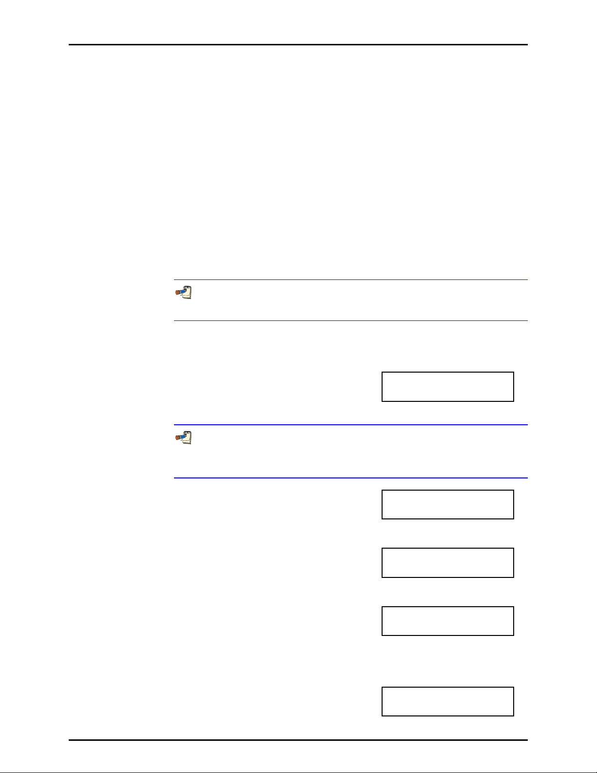
3. OPERATION
A File AutoTest definition file defines:
• The identifying number of the File AutoTest definition file.
• Pressure measurement mode (gauge or absolute).
• Pressure unit of measure.
• DUT full scale in pressure unit of measure and measurement mode.
• DUT tolerance (% FS).
• Number of test points or pressure targets to include in the AutoTest.
• Numerical value of each test point or pressure target.
See Section 3.3.10, OPERATION for information on running a Quick or File
AutoTest.
See Section 3.4.5.1 for information on viewing the data files that result from
running a Sequence.
See Section 3.3.10, OPERATION, for information on RUNNING a Quick or File
AutoTest.
OPERATION
To access the AutoTest definition viewing and editing functions press [SETUP],
<5ATest>, <2file>. Select <1view> to view an AutoTest definition file. Select
<2edit> to edit an AutoTest definition file.
When <2edit> is selected the display is:
Edit File AutoTest #
1
Enter the number (1 - 40) of the File AutoTest to be edited.
To create a File AutoTest definition file similar to an existing definition file
without entering all the definition information, edit an existing definition file and at
the end of the editing process, save it as a different file number.
The display is:
Measurement mode:
1absolute 2gauge
The cursor is on the current selection. Select the desired pressure measurement
mode for the AutoTest (see Section 3.3.3).
The display is:
1psi 2MPa 3kPa
4bar
The unit of measure selection screen is the current [UNIT] selection screen (see
Section 3.3.2). Select the desired pressure measurement unit for the AutoTest.
The display is:
DUT full scale:
6000 psi g File1
Enter the full scale pressure of the DUT to be calibrated with this File AutoTest.
The value entered will be used along with the DUT tolerance to AutoRange
RPM4 settings when the File AutoTest is run (see Section 3.3.10,
PRINCIPLE).
The display is:
DUT tolerance:
0.25% FS File1
Page 53 © 2007 DH Instruments, a Fluke Company
Page 64

RPM4/HPMS A70M/A20M-AF OPERATION AND MAINTENANCE MANUAL
Enter the tolerance in % of full scale (measurement uncertainty, precision or
accuracy as desired) of the DUT to be calibrated using this File AutoTest. The
value entered will be used along with the DUT full scale to determine RPM4
AutoRange settings when the AutoTest is run (see Section 3.3.10,
PRINCIPLE).
The display is:
Enter the total number of pressure points or target pressures to be included in
the AutoTest. The maximum number of points is 21. If data is to be taken at
“zero” pressure, include the “zero” points in the point count.
The display is:
Enter the numerical value of the target pressure point <N>. Repeat until all of the
points in the File AutoTest have been defined.
After entering the last pressure target, the
display is:
Enter the identifying number under which this File AutoTest definition file should
be saved. A confirmation is required to overwrite and existing sequence.
While editing a File AutoTest, pressing [ESC] backs through entries until editing
of the pressure target values has begun. Then [ESC] can only be used to
abandon editing.
3.5 [SPECIAL]
PURPOSE
Number of targets:
1 File1
Pressure target N:
0.00 psi g File1
Save as File
AutoTest #:1
[SPECIAL] accesses a menu of RPM4 functions and features that are less commonly used or not
normally used in regular operation.
OPERATION
1AutoZ 2remote 3head
Press [SPECIAL] from the MAIN RUN screen to access the
SPECIAL menu. The display is:
4SDS 5prefs 6Punit
7intern 8cal 9reset
Some screens, such as the SPECIAL menu, go beyond the two lines provided by the display. This is indicated
by a flashing arrow in the second line of the display. Press the cursor control keys to move the cursor to access the
lines that are not visible or directly enter the number of the hidden menu choice if you know it.
SPECIAL menu choices include:
<1AutoZ> Manage the AutoZero function for the active Q-RPT (see Section 3.5.1).
<2remote> View and edit COM port (RS-232) and IEEE-488 interface settings. Select remote syntax
style (see Section 3.5.2).
<3head> Set HEAD function fluid and height unit of measure (see Section 3.5.3).
<4SDS> Feature not used in this RPM4 model.
<5prefs> View and set screen saver time, keypad sound frequency, unit ID number, time/date,
security protection level (see Section 3.5.5).
<6Punit> Customize the [UNIT] key pressure unit of measure selections (See section 3.5.6).
© 2007 DH Instruments, a Fluke Company Page 54
Page 65

3. OPERATION
<7intern> Access internal functions including on-board barometer viewing, read rate adjustment, incid ent
log viewing (see Section 3.5.7).
<8cal> View and adjust RPM4 Q-RPT and barometer calibration coefficients (see Sections 3. 5.8, 5.2, 5.3).
<9reset> Access RPM4’s various reset functions (see Se ct ion 3.5.9).
3.5.1 <1AUTOZ>
PURPOSE
To turn ON and OFF the AutoZ function that offsets the RPM4 Q-RPT readings relative to a
reference value in order to compensate for possible Q-RPT zero drift between full
recalibrations. To view and adjust the value of the AutoZ offset.
To RUN the AutoZ routine that rezeroes the Q-RPT, use [AutoZ] (see Section 3.3.9).
PRINCIPLE
AutoZ Purpose and Principle
The main component of the change over time of the RPM4 Q-RPTs is change in zero or
offset, independent of span. Offsetting or “rezeroing” RPM4 Q-RPTs relative to a reference
between recalibrations allows measurement uncertainty specifications to be maintained with
less frequent full calibrations. The RPM4 AutoZero function (AutoZ) provides full on-board
support for the rezeroing process to simplify its regular application by the user.
The AutoZero function uses three values:
1. P
: The pressure value indicated by the AutoZ reference, the device that is acting as th e
std,0
reference relative to which to off set the RPM4 Q-RP T.
In absolute measurement mode, the pressure at which AutoZ is performed is normally
atmospheric pressure and the P
value can be supplied a) by manual entry, b)
std,0
automatically from a DHI RPMx connected to RPM4’s COM2 communications port, or c)
automatically from the Lo Q -RPT for t he Hi Q-RPT.
In gauge measurement mode, P
is always zero (atmospheric pressure) which is
std,0
supplied by definition when the Q-RPT is vented to atm osphere.
2. P
: The pressure reading of the Q-RPT, with no AutoZ offset, at the time AutoZ is
u,0
performed.
3. P
P
offset
(P
std,0
(P
and P
offset,G
) and the AutoZ standard (P
u,0
represents the difference between the Q-RPT reading (P
: The difference between the reading of the Q-RPT with no AutoZ offset
offset,A
) for gauge (G) and absolute(A) measurement mode:
std,0
P
offset
= P
u,0
- P
std,0
) and the AutoZ standard
u,0
). The AutoZ function manages the determination, storage and application of P
offset
to
correct the zero offset in absolute and gauge measurement modes.
When the Q-RPT is calibrated, P
intervals using the AutoZ function. The most recent value of P
is set to zero. P
offset
is then redetermined at regular
offset
is applied to the Q-RPT
offset
reading to correct for zero drift.
The AutoZ function can be turned ON and OFF. Table 5 summarizes the effect of AutoZ ON
and OFF in absolute and gauge measurement modes.
AutoZ in absolute measurement mode
The RPM4 A70M/A20M-AF Q-RPTs are intrinsically absolute. They have an evacuated and
sealed reference and naturally measure absolute pressure (difference from vacuum).
In absolute measurement mode, the source of P
must be an absolute pressure, nominally
std,0
atmospheric pressure, with uncertainty significantly better than that of the Q-RPT that is
Page 55 © 2007 DH Instruments, a Fluke Company
Page 66
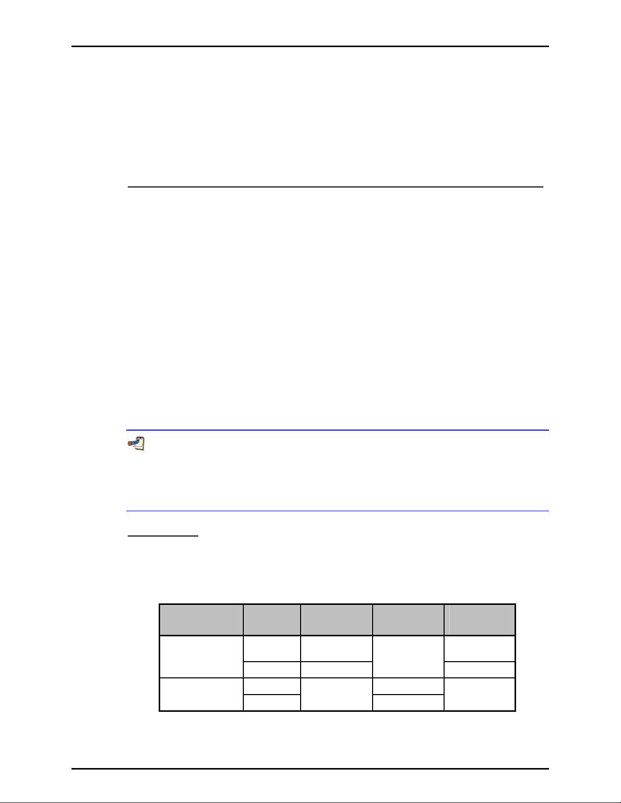
RPM4/HPMS A70M/A20M-AF OPERATION AND MAINTENANCE MANUAL
being AutoZeroed. Given the high pressure range of the RPM4 Q-RPTs, adequate
uncertainty is easily available from a variety of digital barometers or, for the Hi Q-RPT, by the
Lo Q-RPT.
In absolute measurement mode, with AutoZ ON, absolute pressure is calculated as:
P
= Pu - P
abs
offset,A
In absolute measurement mode, running the AutoZ function to update the AutoZ value
(P
), is initiated by the operator using [AutoZ] (see Section 3.3.9.1).
offset,A
AutoZ in gauge measurement mode, dynamic compensation for atmospheric pressure
The RPM4 A70M/A20M-AF Q-RPTs are intrinsically absolute but they are also used in gauge
measurement mode (difference from atmosphere). Gauge measurement mode is achieved
by subtracting the value of atmospheric pressure from the Q-RPT’s absolute reading using
AutoZ and by dynamically compensating for changes in atmospheric pressure between
opportunities for AutoZ to execute (see Section 3.2.2, PRINCIPLE).
In gauge measurement mode, the value of P
is always zero gauge pressure. Zero gauge
std,0
pressure, by definition, is applied to the Q-RPT when it is vented to atmosphere. Gauge
pressure is the measured absolute pressure, P
P
= Pu - P
gauge
, minus P
u
offset,G
offset,G
.
When AutoZ is ON, dynamic compensation for atmospheric pressure is also applied to
compensate for changes in atmosph eric pressure as measured by RPM4’s o n-board barometer
) between AutoZ updates (see Section 3.2.2). The measured gauge pressure is
(ΔP
atm
calculated using ΔP
to correct the value of P
atm
P
= Pu - P
gauge
offset.G
offset.G
.
- ΔP
atm
In gauge measurement mode, running AutoZ is initiated by the operator pressing [AutoZ]
(see Section 3.3.9.1) when the RPM4 is vented. This assures regular updating of the value
offset,G
and P
of P
When gauge mode is first activated, the value of P
atm,0
. ΔP
is continuously updated automatically.
atm
offset.G
subtracted from the absolute
pressure reading to achieve gauge pressure is standard atmosphere of 101.325 kPa. This can
cause a large zero error when gauge mode is activated if atmospheric pressure is significantly
different from standard atmospheric pressure. When gauge mode is activated, always vent the
RPM4 Q-RPT and press [AutoZ] to run AutoZ and obtain an actual value of P
offset.G
.
AutoZ ON/OFF
The AutoZ function can be turned ON and OFF separately for gauge and absolute
measurement modes. Table 5 summarizes the effect of AutoZ ON and OFF. Generally,
AutoZ should always be left ON.
Table 5. AutoZ ON and OFF
MEASUREMENT
MODE
Absolute
Gauge
© 2007 DH Instruments, a Fluke Company Page 56
AutoZ
STATUS
ON YES
OFF NO
ON YES
OFF
P
offset
APPLIED
YES
ΔP
atm
APPLIED
Not Applicable
NO
AutoZ
ROUTINE
RUNS
When initiated
by operator
Not available
When initiated
by operator
Page 67

3. OPERATION
Recommendations for the Use of the AutoZ Function
The AutoZ function provides a powerful and easy to use tool for improving the stability over
time of RPM4 Q-RPTs and maximizing the recalibration interval by compensating for zero
drift between full recalibrations. The following simple recommendations will help assure that
you use this feature to best advantage.
• In gauge mode: Always leave AutoZ ON. Use [AutoZ] to run AutoZ whenever RPM4 is
vented and displays a significantly non-zero value. Wait at least 2 minutes after venting before
running AutoZ.
• In absolute measurement mode: Always leave AutoZ ON. Use [AutoZ] to run AutoZ every
approximately every 30 days or when RPM4 has been exposed to a temperature change
exceeding 15 ºC (36 ºF). AutoZero the Lo Q-RPT against a barometer with measurement
uncertainty of ± 0.04 psi (275 Pa) or better (note that this is only 0.3% of atmospheric pressure
so a relatively low accuracy barometer is adequate). AutoZero the Hi Q-RPT against the Lo QRPT. Wait 5 to 10 minutes before running AutoZero in absolute mode.
The AutoZ function and values are Q-RPT AND measurement mode (gauge or absolute)
specific.
OPERATION
To RUN the AutoZ routine that rezeroes the Q-RPT, use [AutoZ] (see Section 3.3.9).
To access the RPM4 AutoZ function press [SPECIAL], <1AutoZ>. The display is:
1. Active Q-RPT designator.
2. Indication of active measurement mode ( <abs> for absolute,
<gage> for gauge).
3. Indication of whether AutoZ is currently ON or OFF for this
Q-RPT and measurement mode.
1off 2view Hi
3edit abs ON
Select <1off> (or <1on>) to change the AutoZ status for the current Q-RPT and
measurement mode from ON to OFF or vice versa.
AutoZ ON is indicated by a <z> in the MAIN RUN screen, top line, third character from the
right. When AutoZ is OFF, the character is blank.
Select <2view> to view the current value of P
P
calibrated. P
should be zero in absolute measurement mode when the RPM4 is new or has just been
offset
should be roughly equal to atmospheric pressure when the Q-RPT is in gauge
offset
for the active Q-RPT and measurement mode.
offset
measurement mode.
Select <3edit> to edit the value of P
(see Section 3.5.1.1).
The value of P
Page 57 © 2007 DH Instruments, a Fluke Company
is always displayed and entered in Pascal (Pa).
offset
for the active Q-RPT and measurement mode
offset
Page 68

RPM4/HPMS A70M/A20M-AF OPERATION AND MAINTENANCE MANUAL
3.5.1.1 EDIT AUTOZ
The edit AutoZ function should be used only with great care as entering
inappropriate values may result in out of tolerance measurements. In normal
operation, the value of the AutoZ offset, P
using [AutoZ] (seen Section 3.3.9).
PRINCIPLE.
To edit the current P
value for the active Q-RPT and measurement mode,
offset
press [SPECIAL], <1AutoZ>, <3edit>. The display is:
offset
Before editing P
, should be changed by running AutoZ
, see Section 3.5.1,
offset
1. Indication of active measurement mode
(<abs> for absolute, <gage> for gauge).
2. Active Q-RPT for which P
3. Edit field for value of P
Edit P
as desired and press [ENT] to activate the new value. Press [ESC] to
offset
is being viewed.
offset
.
offset
Poffset, Abs Hi
275 Pa
abandon changes.
The value of P
is always displayed and entered in Pascal (Pa).
offset
3.5.2 <2REMOTE>
PURPOSE
To configure the RPM4 COM1, COM2 and IEEE-488 (GPIB) communication ports. To test COM1
and COM2 communications. To select the remote programming communications format.
PRINCIPLE
The RPM4 has two RS-232 communications ports referred to as COM1 and COM2 and a
single IEEE-488 (GPIB) port. COM1 or the IEEE-488 port is for communicating with a host
computer (see Section 4), and COM2 is reserved for communicating with an external device
(e.g. an RPMx, a multimeter, etc.). These ports’ settings can be viewed and changed using
[SPECIAL], <2remote>.
RPM4 has two remote communications formats, classic and enhanced (see Section 4.3). Th e
active format can be selected.
A self test is supplied for RS-232 communications. The self test allows verification that the
RPM4 RS232 ports (COM1 and COM2) are operating properly and that a valid interface
cable is being used.
OPERATION
To access the communications settings, press [SPECIAL], <2Remote>.
• Select <1COM1> to view and edit COM1 settings (see Section 3.5.2.1.).
• Select <2COM2> to view and edit COM2 settings (see Section 3.5.2.1.).
• Select <3IEEE> to view and edit IEEE-488 settings (see Section 3.5.2.2).
• Select <4format> to select the remote communications command format (see Section 3.5.2.3).
• Select <5RS232test> to run the COM1 and COM2 communications test (see Section 3.5.2.4).
© 2007 DH Instruments, a Fluke Company Page 58
Page 69

3. OPERATION
3.5.2.1 <1COM1, 2COM2>
The COMx ports can be set for specific communications settings. The settings
are baud rate, parity, data bits and stop bits. The available options are:
Baud 300, 600, 1 200, 2 400, 4 800, 9 600, 19 200, 28 800, 38 400
Parity NONE, ODD or EVEN
Length 7 or 8
Stop Bit 1 or 2
The default is <2 400, E, 7,1> for both COM1 and COM2.
The user can also specify one or two termination characters, referred to as
“Term1” and “Term2”, as well as define these characters. These define the
characters that mark the end of commands that are sent to the RPM4 as well as
mark the end of replies sent back to the host computer. The RPM4 typically uses
the <Term1> character to mark the end, and will ignore the <Term2> character.
The characters can be any decimal number from 1 to 255. The defaults are
<13> (carriage return) and <10> (line feed) and usually should not be changed.
3.5.2.2 <3IEEE-488>
The IEEE-488 port’s primary address can be set from 1 to 31 in this screen.
The factory default value is 10. Secondary addressing is not used or supported.
This address must not conflict with the address of any other device on the same
IEEE-488 bus.
The receiving terminating character must be a line feed and EOI. Carriage returns
are ignored if received. The RPM4 sends a line feed and asserts the EOI line to
terminate a reply. These settings are fixed to agree with IEEE Std. 488 .2. If you
change the address, the IEEE inte rface wi ll reset (PON) and becom e idle.
3.5.2.3 <4FORMAT>
The RPM4 has two different syntax formats available for the remote program
commands.
The classic remote command format is highly intuitive and conforms with previous DHI
PPC and RPM products.
The enhanced remote command format generally uses the same commands as the
classic format, but in addition it follows the syntax, format, and status reporting
features of IEEE Std 488.2.
The details of each format are covered in Section 4.3.
[SPECIAL], <2remote>, <4format> allows the remote program command syntax to
be selected. The cursor is on the active format. Select <1classic> or <2enhanced>
as desired.
3.5.2.4 <5RS232 SELF-TEST>
The RS232 self-test is provided to check the RPM4 COM ports and the interface
cable independently of an external device or computer.
If you are having difficulty communicating with RPM4 from a host computer
using RS232, the RS232 self test can help establish that the RPM4 COM1 port
you are trying to communicate with and the interface cable you are using are good.
To run a self test of the RS232 ports (COM1 and COM2), press [SPECIAL],
<2remote>, <5RS232test>.
Page 59 © 2007 DH Instruments, a Fluke Company
Page 70

RPM4/HPMS A70M/A20M-AF OPERATION AND MAINTENANCE MANUAL
The display prompts you to connect COM1 to COM2 using a standard pin-to-pin
DB-9F to DB-9M RS232 cable (see Section 4.2.1.1, 4.2.1.3).
Once the cable has been installed, press [ENT] to run the self-test. The test is first
executed in the COM1→COM2 di rection and th en in the COM2→COM1 direction.
If the COM1→COM2 test passes: <PASSED> displays briefly and the test
proceeds to COM2→COM1.
If COM2→COM1 passes: <PASSED> is displayed briefly followed by the
conclusion, <The RS232 test has PASSED>.
If a test fails: Execution is suspended until [ENT] is pressed.
The RPM4 RS232 test can fail for three reasons:
1. The RS232 cable being used is incorrect (Section 4.2.1.1, 4.2.1.3 for information
on the correct cable).
2. COM1 and COM2 do NOT have the same serial communications settings and
therefore cannot communicate together (see Section 3.5.2.1 to set the
COM ports).
3. COM1 or COM2 is defective.
The reason for failed communications is almost always a cable or incorrect RS232
interface settings. Be sure that these are correct before concluding that a COM port
is defective.
3.5.3 <3HEAD>
PURPOSE
To view or change the properties of the HEAD function (see Section 3.3.7) including the unit of
measure of length for head height entry and the test fluid type and species for density calculations.
OPERATION
From the MAIN RUN screen, press [SPECIAL], <3Head>.
Select the desired height unit of measure and press [ENT].
Select <1gas> or <2liqud> depending on the pressurized medium between the RPM4 and
the height at which pressure is to be calculated. Select the gas or liquid species. The liquid
selection <3User>, is to create a custom liquid with a user entered density.
Use [HEAD] to set a head height if desired.
3.5.4 <4SDS>
PURPOSE
This feature is not used in RPM4 A70M/A20M-AF.
3.5.5 <5PREFS>
PURPOSE
To access a menu of RPM4 operational preferences and functions.
OPERATION
© 2007 DH Instruments, a Fluke Company Page 60
Page 71
3. OPERATION
To access the PREFS menu press [SPECIAL],
<5prefs>. The display is:
1ScrSvr 2sound 3time
4ID 5level
The PREFS menu includes:
<1ScrSvr> View and change the screen saver activation time (see Section 3.5.5.1).
<2sound> View and change the key press sounds (see Section 3.5.5.2).
<3time> View and edit the internal time and date settings (see Section 3.5.5.3).
<4ID> View the RPM4 serial number (SN) and view or edit the ID number
(see Section 3.5.5.4).
<4level> View and set the user security level and/or password (see Section 3.5.5.5).
3.5.5.1 <1SCRSVR>
PURPOSE
To adjust the idle time after which RPM4’s SCREEN SAVER activates.
PRINCIPLE
RPM4 has a SCREEN SAVER function which causes the display to dim after a
front panel key is NOT pressed for a certain amount of time . The default is for the
screen saver to activate after 10 idle minutes. The screen saver activation time
can be adjusted by the user or screen saving can be completely eliminated.
Setting screen saver time to zero eliminates the SCREEN SAVER function so
that the display permanently remains at full brightness.
OPERATION
To access the SCREEN SAVER function, press [SPECIAL], <5prefs>,
<1ScrSav>. Edit, in minutes, the idle time after which screen saver will activate
to dim the screen. Set the time to zero to eliminate t he SCREEN SAVER function.
3.5.5.2 <2SOUND>
PURPOSE
To adjust or suppress the RPM4 valid key press sound.
See Section 3.1.4 for information on the complete list of sounds made by
RPM4 and their meanings.
PRINCIPLE
RPM4 provides audible feedback by a brief “beep” when a valid key press is
made. The tone frequency of this beep may be selected from three choices or it
may be completely suppressed. Invalid key presses are indicated by a
descending two tone “blurp” which cannot be suppressed.
OPERATION
To access the keypad sound adjustment function press [SPECIAL], <5prefs>, <2sound>.
Select between <2lo>, <3mid> or <4hi> to adjust the valid key press tone frequency.
Select <1none> to suppress the valid key press tone.
Page 61 © 2007 DH Instruments, a Fluke Company
Page 72
RPM4/HPMS A70M/A20M-AF OPERATION AND MAINTENANCE MANUAL
The sound function only affects the valid key press tone. The invalid key press
tone and other RPM4 sounds cannot be adjusted or suppressed.
3.5.5.3 <3TIME>
PURPOSE
To view and edit the RPM4 internal time and date settings.
OPERATION
To access the TIME function
press [SPECIAL], <5prefs>, <3time>.
The display is:
Edit: 1time 2date
08:32:11 am 20030125
Select <1time> to edit the time. Edit hours, then minutes, then am/pm by
pressing [ENT] after each entry. Seconds go to zero when minutes are entered.
This can be used to synchronize the time with a time standard.
Select <2date> to edit the date. The date must be specified in YYYYMMDD format.
The RPM4 date and time are set to United States Mountain Standard Time in
the final test and inspection process at the factory. If desired, use the TIME and
DATE function to set your local time and date.
3.5.5.4 <4ID>
PURPOSE
To view or edit the RPM4 user ID and to view the RPM4 serial number.
OPERATION
To access the ID function press [SPECIAL], <5prefs>, <2ID>.
Select <1view> to view the current ID.
Select <2edit> to edit the ID.
The ID has twelve characters. When the edit screen is opened, the cursor is on
the first character. Numerical values can be entered directly from the keypad. In
addition, the cursor control keys can be used to toggle through a list of available
alphanumeric characters. Holding the key slews through the characters.
Character order going up is: blank space, symbols, lower case letters, upper
case letters, numbers. After selecting a character, press [ENT] to activate it and
move to the next character field.
When a character is selected the cursor moves to the next character. To leave a
blank character, press [ENT] with the field for that character blank. Use this for
the trailing characters if the ID being entered is less than twelve characters.
After the last of the twelve characters has been entered, the <Save ID?> option is offered.
Select <1no> to return to the ID edit screen. Select <2yes> to save the edited ID.
The ID can be set remotely from a computer which is quite a bit more
convenient than entering characters from the keyboard (see Section 4.4.4, “ID”
command). The ID is not cleared or reset by any RESET function
(see Section 3.5.9).
© 2007 DH Instruments, a Fluke Company Page 62
Page 73

3. OPERATION
3.5.5.5 <5LEVEL> (SECURITY)
PURPOSE
To set user protection levels to restrict access to certain functions and to edit the
password required for changing user levels.
PRINCIPLE
RPM4’s front panel user interface provides the means to access all RPM4 user
defined data, settings and functions including calibration data. Inadvertent,
uninformed or unauthorized altering or deleting of data, settings and functions
could require extensive reconfiguration by the user and might cause invalid
readings and behavior. For these reasons, depending upon the application in
which RPM4 is being used, it may be desirable to restrict access to some
functions. The user level function pr ovides a means of restrictin g ac ce s s to c er ta i n
functions. Four different levels of security are available.
Access to changing security levels can be left open, or be protected by a password.
Security Levels
The security levels are structured to support typical operating environments as follows:
None This level is intended for use only by the system manager and/or
calibration facility. It allows access and editing in all areas including
critical metrological information.
Low Low security is designed to protect the specific metrological
information and SYSTEM DIAGNOSTIC AND MAINTENANCE
functions of the system against accidental alteration. It is intended for
an advanced operator performing many different tasks. Low security
is the default user level setting.
Medium Medium security is designed to protect specific metrological
information in the system and to assure that the RPM4 is operated
using consistent operational parameters.
High High security is designed to protect all operating parameters. It is
intended to minimize operator choices, for example to perform
repeated identical calibrations under consistent conditions.
RPM4 is delivered with the security level set at low to avoid inadvertent altering
of critical internal settings but with access to changing security levels unrestricted.
It is recommended that the low security level be maintained at all times. If there is a
risk of unauthorized changing of the security level, changing authority should be
password protected (see OPERATION of this section).
Page 63 © 2007 DH Instruments, a Fluke Company
Page 74

RPM4/HPMS A70M/A20M-AF OPERATION AND MAINTENANCE MANUAL
The security levels are structured to support typical levels of operation as shown
in Table 6. Specifically, the security levels prevent execution of the functions
accessed by the key strokes marked by “•”:
Table 6. Security levels
FUNCTION LOW MEDIUM HIGH
[RANGE]
[ENT] (AutoTest)
[UNIT]
[MODE]
[AutoRange]
[LEAK CK]
[DISPLAY]
[HEAD]
[SDS] (NOT USED IN THIS RPM4 MODEL)
[AutoZ] (in absolute mode)
[SETUP]
[SETUP], <1range>
[SETUP], <2res>
[SETUP], <4UL>
[SETUP], <5ATest>
[SPECIAL]
[SPECIAL], <1AutoZ>
[SPECIAL], <1AutoZ>, <1on/1off>
[SPECIAL], <1AutoZ>, <3edit>
[SPECIAL], <2remote>
[SPECIAL], <2remote>, make changes
[SPECIAL], <3head>
[SPECIAL], <4SDS> (NOT USED IN THIS RPM4 MODEL)
[SPECIAL], <5pref>, <1ScrSvr>
[SPECIAL], <5pref>, <2sound>
[SPECIAL], <5pref>, <3time>
[SPECIAL], <5pref>, <3time>, make changes
SPECIAL], <5pref>, <4ID>, <2edit>
[SPECIAL], <6Punit>
[SPECIAL], <7internal>
[SPECIAL], <7internal>, <3RPT2x> (NOT USED))
[SPECIAL], <7interrnal>, <5log>, clear log
[SPECIAL], <8cal>
[SPECIAL], <8cal>, <2edit> under any selection
[SPECIAL], <4reset>
[SPECIAL], <4reset>, <4cal>
[SPECIAL], <4reset>, <5all>
Remote communications disabled
“•” indicates the function/menu is NOT accessible.
•
•
•
•
• •
•
• •
•
• •
•
• •
• •
• •
• •
•
• •
• • •
• • •
•
• •
• •
• •
• •
• •
• •
• • •
• • •
• •
• •
• • •
• • •
• •
• • •
• •
• • •
• • •
•
© 2007 DH Instruments, a Fluke Company Page 64
Page 75
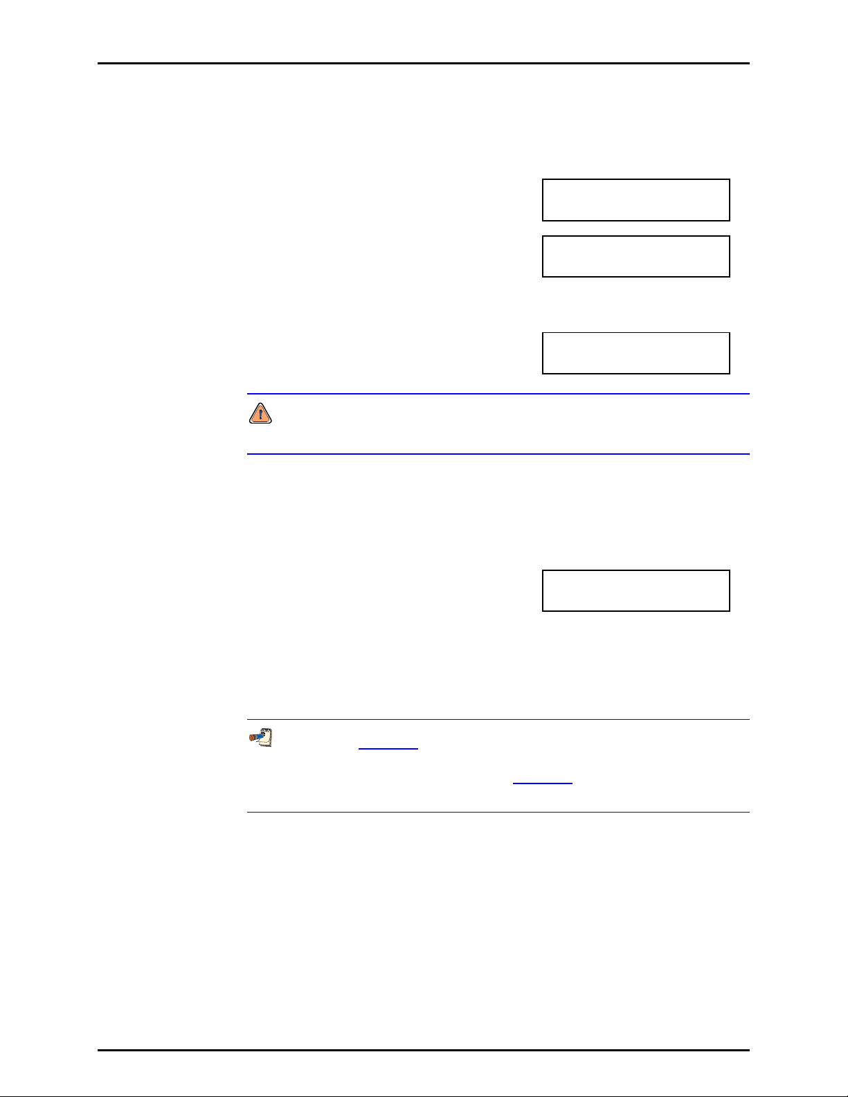
3. OPERATION
OPERATION
RPM4 is delivered with no active password and access to the User Level menu is
open. The use r le vel is set t o <1Low>. User levels can be changed freely until a
password has been created.
To access the LEVEL function
press [SPECIAL], <5prefs>, <5level>.
The display is:
Selecting <1change user level> brings
up the restriction menu:
1change user level
2edit password
Restrictions: 1none
2low 3medium 4high
The cursor is on the current restriction level. Select a different level or
or [ESC] back to the MAIN RUN screen.
If no password is active, selecting
<2edit password> displays the user
password and allows it to be edited.
Password: pppppp
0 disables password
Once a password has been entered, the user level cannot be changed without
reentering the password.
Passwords can be up to six numbers in length and cannot start with a zero.
If <0> is entered, the password is made inactive and the user will not be required
to enter a password to access the user level menu. This condition, with a
security level of <2low>, is the factory default.
If there is an active password, the
RPM4 password entry screen appears.
The user must enter the user defined
password or the factory secondary
RPM4 SNnnnn-xx
Password: pppppp
password to proceed further:
The first field, <nnnn>, is the serial number of the RPM4, followed by a second field,
<xx>, that represents the number of times that a secondary password has been
used. The second field, <xx>, increments each time a secondary password is
used. The third field, <pppppp> is for user entry of the normal password.
The factory secondary password is available in case the user’s password has
been misplaced or forgotten. It can be obtained by contacting a DHI Authorized
Service Center (see Table 23). The factory secondary
password is different for all
RPM4’s and changes each time it is used.
3.5.6 <6PUNIT>
PURPOSE
To customize the selection of pressure units of measure that are available in the [UNIT] key menu.
PRINCIPLE
The [UNIT] function key makes available a choice of four default pressure units (psi, MPa,
kPa, bar) (see Section 3.3.2). RPM4 also supports many commonly used units other than those
included in the default set up. These units can be made available for active selection by
customizing the UNIT function using [SPECIAL], <6PresU>. This allows RPM4 to offer a
very wide selection of units while simplifying day to day operation. The typical user
Page 65 © 2007 DH Instruments, a Fluke Company
Page 76

RPM4/HPMS A70M/A20M-AF OPERATION AND MAINTENANCE MANUAL
customizes the [UNIT] function key to support his/her most commonly used units. Up to six
units can be included in the [UNIT] screen.
OPERATION
To customize the [UNIT] function key, press [SPECIAL], <6PresU> from the MAIN RUN
screen. The display is:
1. Entry field to specify which unit position (1 to 6) of the [UNIT]
function key menu is to be changed.
Enter the number of the unit position that you would
like to change. The display becomes:
Set up unit #6
Unit#6 1SI 2other
3altitude 4user
Select the desired pressure unit category (SI units include units based on SI units such as
mmHg), then select the desired unit from the unit menu. Note: <3altitude> is not available in
this RPM4 model.
The units of measure available are listed in Table 7.
Table 7. UNIT function - available units of measure
<1SI> <2OTHER> <3ALTITUDE
<1Pa>
<2hPa>
<3kPa>
<4MPa>
<5mbar>
<6bar>
<7mmHg>
<8mmWa>
<1psi>
<2psf>
<3inHg>
<4inWa>
<5kcm2>
>
Not available
in this RPM4
model
<4USER>
If <4user> is selected, the user unit must be defined. The display is:
Define user unit:
1. Entry field.
1.000000 unit/Pa
Enter the number of user units per Pascal (Pa) in the entry field. Pressing [ENT] defines the
user unit and returns to the <Set up unit #n> screen.
The user defined unit label can be customized to any alphanumeric, four character label
using the remote command “UDU” (see Section 4.4.4).
See Section 7.1.1 for the pressure unit conversion factors used by RPM4.
3.5.7 <7INTERNAL>
PURPOSE
To view, set, adjust, and maintain various aspects of RPM4’s internal operation.
OPERATION
To access the internal selections press [SPECIAL],
<7internal>. The display is:
© 2007 DH Instruments, a Fluke Company Page 66
1baro 2ReadRt 3RPT2x
4lo vnt 5log
Page 77
3. OPERATION
The INTERNAL menu choices include:
<1baro> View the real time output of the RPM4 on-board barometer (see Section
3.5.7.1).
<2ReadRt> Turn ON and OFF RPM4’s automated, rate of change dependent, reading
and integration and display rate feature (see Section 3.5.7.2).
<3RPT2x> Feature not used in this RPM4 model.
<4lo vnt> Feature not used in this RPM4 model.
<5log> View the RPM4 incident log (see Section 3.5.7.5).
3.5.7.1 <1BARO>
PURPOSE
To view the value of atmospheric pressure as measured by the RPM4 on-board
barometer.
PRINCIPLE
RPM4 A70M/A20M-AF is equipped with an on-board barometer. The atmospheric
pressure measurements made by the on-board barometer are used for dynamic
compensatio n o f a t mos p h er ic pressure w hen making gauge pressure measurements
(see Sections 3.2.2, 3.3.3, PRINCIPLE).
See Section 5.4,4 Figure 13 and Section 5.4.5, Figure 14 for a photo and
schematics showing the position of the on-board barometer in RPM4.
The on-board barometer is a low accuracy sensor used only for measuring
small changes in atmospheric pressure over short periods of time
(see Section 3.2.2). RPM4 measurement uncertainty does not depend on the
measurement uncertainty of the on-board barometer.
OPERATION
To view the current reading of the on-board barometer press [SPECIAL],
<7internal>, <1baro>. The display is in the active pressure unit of measure
(see Section 3.3.2). The display resolution is fixed to 0.1 Pa, or its equivalent.
3.5.7.2 <2READRT>
PURPOSE
To turn ON and OFF RPM4’s automated, rate of change dependent, reading
integration and display rate feature.
PRINCIPLE
To obtain maximum resolution from RPM4 Q-RPT pressure measurements, an
integration time of about 1.2 second per reading is used. In most situations,
maximum precision is needed when pressures are stable so a relatively slow
display update rate presents no disadvantage. However, when pressure is
changing quickly, more rapid pressure updates are usually more important than
obtaining maximum precision on individual readings. The RPM4 read rate
function automatically adjusts pressure measurement integration time depending
on the rate of change of pressure. When pressure is changing rapidly, reading
rate is increased. When pressure is evolving slowly, reading rate is decreased
and maximum precision is obtained.
Page 67 © 2007 DH Instruments, a Fluke Company
Page 78
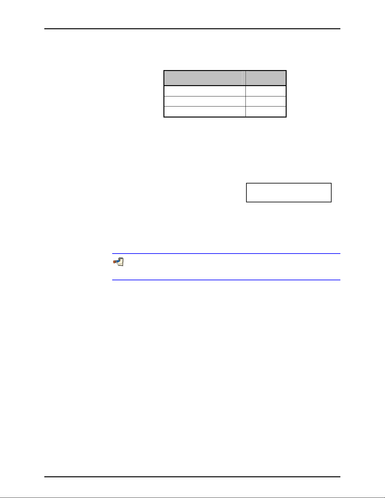
RPM4/HPMS A70M/A20M-AF OPERATION AND MAINTENANCE MANUAL
When the automated read rate function is ON, three pressure rate of change
dependent read rates are used. The result is three display update rates:
Table 8. READRT - display update rates
PRESSURE
RATE OF CHANGE
> 3 % of range span/s
> 0.5 and < 3 % of range span/s
< 0.5 % of range span/s
DISPLAY
UPDATE
≈ 0.2 s
≈ 0.6 s
≈ 1.2 s
For situations in which maximum reading precision is desired regardless of pressure
rate of change, the RPM4 automated read rate function can be turned OFF.
In this case, the reading rate is always the high resolution rate of about 1.2 readings
per second.
OPERATION
To turn the automated read rate function ON or OFF or check its current status,
press [SPECIAL], <7internal>, <3ReadRt>.
The display is:
Auto read rate: H3
1on 2off
The cursor is on the current selection.
Selecting <1on> activates the automated reading rate and returns to the MAIN
RUN screen. Selecting <2off> turns OFF the automated reading rate and
returns to the MAIN RUN screen.
The default RPM4 condition is auto read rate ON.
Auto read rate ON/OFF is NOT Q-RPT or range specific. Turning auto read rate
ON or OFF in one range turns it ON or OFF for all RPM4 ranges.
3.5.7.3 <3RPT2X>
PURPOSE
This feature is not used in this RPM4 model.
3.5.7.4 <4LO VNT>
PURPOSE
This feature is not used in this RPM4 model.
3.5.7.5 <5LOG>
PURPOSE
To view and/or clear the RPM4 event log.
PRINCIPLE
RPM4 records to a log each time one of the following events occurs:
• Pmax! of an internal RPM4 Q-RPT is exceeded (see Section 3.4.4.1).
• A memory fault occurs.
© 2007 DH Instruments, a Fluke Company Page 68
Page 79

3. OPERATION
OPERATION
To view the event log press [SPECIAL], <7internal>, <5log>. The oldest logged
event appears. Pressing [ENT] steps through the logged events from the oldest
to the most recent and ending with the option to clear the log, <1no>, <2yes>.
The log clear choice is not available in all security levels (see Section 3.5.5.5, Table 6).
When all events have been viewed, <End of log> displays.
3.5.8 <8CAL>
PURPOSE
To calibrate the RPM4 Hi and Lo Q-RPTs and adjust the on-board barometer. These
functions are considered part of RPM4 maintenance and are covered in the maintenance
section of this manual (see Sections 5.2, 5.3).
3.5.9 <9RESET>
PURPOSE
To reset various RPM4 settings to default or factory values.
PRINCIPLE
RPM4 stores its user definable settings in non-volatile memory. The reset menu allows the
user to selectively or completely reset these settings to factory defaults. This clears any
settings that the user has made, and should be used only to restore the RPM4 to a known
state. RPM4 goes through its power up sequence after any type of reset is executed.
RPM4 reset functions will change current settings to factory defaults. These may include
settings vital to RPM4 operation and affecting the calibration of the quartz reference pressure
transducers (Q-RPTs). Reset functions should only be used by qualified personnel with knowledge of
reset consequences. Reset functions should never be used “experimentally”.
OPERATION
To access the RESET menu, press [SPECIAL],
<9reset>. The display is:
1sets 2units 3ATest
4cal 5all
RESET menu choices include:
<1set> to reset general system operating parameters (see Section 3.5.9.1).
<2units> to reset unit of measure functions (see Section 3.5.9.2).
<3ATest> to reset AutoTest parameters, clear File AutoTest files and clear the AutoTest data
log (see Section 3.5.9.3).
<4cal> to reset internal calibration coefficients and modes (see Section 3.5.9.4).
<5all> to reset all settings except ID and security password to factory default values
(see Section 3.5.9.5).
3.5.9.1 <1SETS>
PURPOSE
Sets most general operating parameters back to default values. Does not affect
calibration coefficients, remote interfaces or AutoRan ge ranges. The Reset – Sets
resets are itemized in Table 9.
Page 69 © 2007 DH Instruments, a Fluke Company
Page 80

RPM4/HPMS A70M/A20M-AF OPERATION AND MAINTENANCE MANUAL
Table 9. Reset – Sets
RESET RESULT SEE SECTION
[UNIT] Pressure unit of measure to first of the six available (psi) 3.3.2
[MODE] Measurement mode to the native mode of the Q-RPT (absolute) 3.3.3
[RANGE] Hi Q-RPT default range (10000 psi) 3.3.1
[HEAD] 0 cm height and Nitrogen medium 3.3.7
Stability Limit 0.005 % of Hi Q-RPT default range 3.4.3
Upper Limit Hi Q-RPT default range default value 3.4.4
Resolution 0.001 % FS of Hi Q-RPT default range 3.4.2
AutoZ AutoZ ON for both Q-RPTs and gauge and asbsolute
AutoZ P
Leak Check 15 second run time. Clear logged results 3.3.5
Screen Saver 10 minutes to activation 3.5.5.1
Key Sounds Medium tone valid key press sound 3.5.5.2
Lo Vnt Automatic 3.5.7.4
ReadRate Automatic 3.5.7.2
measurement modes. Z
set to 101.325 kPa a 3.5.1, 3.2.2
atm,0
value not affected
offset
3.5.1
3.5.9.2 <2 UNITS>
PURPOSE
Sets the pressure units available under the UNIT function to default selections
depending (see Section 3.3.2).
Sets the user defined unit to 1.000/Pa (see Section 3.5.6).
Sets the reference temperature for inWa unit to 20°C.
3.5.9.3 <3ATEST>
PURPOSE
• Resets Auto Tests to default characteristics (see Section 3.3.10).
• Clears File AutoTest definition files (see Section 3.4.5.2).
• Clears AutoTest results data logs (see Section 3.4.5.1).
© 2007 DH Instruments, a Fluke Company Page 70
Page 81

3. OPERATION
3.5.9.4 <4 CAL>
The Reset - Cal function will reset the Q-RPT and barometer calibration
coefficients and reset AutoZ values to zero. This will change the RPM4 calibration
and could cause it to make out of tolerance measurements.
PURPOSE
Clears all user values affecting the calibration of Q-RPTs and the on-board
barometer. The Reset – Cal resets are itemized in Table 10.
Table 10. Reset – Cal
RESET RESULT SEE SECTION
All Q-RPT calibration
coefficients
Q-RPT absolute mode ON 5.3.5
On-board barometer
calibration coefficients
Calibration date Set all dates to 19800101 5.3.7
AutoZ values All P
AutoZ function ON, all Q-RPT s, all measurement modes 3.5.1
PA to zero, PM to 1 5.3.1
PA to zero, PM to 1 5.2.2
values to zero for absolute mode and
offset
101325 Pa for gauge and negative gauge modes
3.5.1
3.5.9.5 <5 ALL>
PURPOSE
The reset - all function clears and deletes large amounts of user defined
information including critical calibration data.
Combines all resets in one global reset command that clears the entire user
section of non-volatile memory except the ID function (see Section 3.5.5.4) and
the security level password (see Section 3.5.5.5) returning RPM4 to the
“as delivered” condition. The Reset – All resets are itemized in Table 11.
Table 11. Reset – All
RESET RESULT SEE SECTION
Reset – Sets All the resets of Reset - Sets 3.5.9.1
Reset – Units All the resets of Reset - Units 3.5.9.2
Reset – Atest All the resets of Reset - ATest 3.5.9.3
Reset – Cal All the resets of Reset - Cal 3.5.9.4
Remote Interfaces COM1, COM2 and IEEE-R88 interfaces to
default settings.
Remote Communications Remote command format to Classic 3.5.2.3
Level (Security) Reset security level to low 3.5.5.5
Parallel Measurement Mode Off 3.5.7.3
3.5.2
Page 71 © 2007 DH Instruments, a Fluke Company
Page 82

RPM4/HPMS A70M/A20M-AF OPERATION AND MAINTENANCE MANUAL
N
N
OOTTEES
S
© 2007 DH Instruments, a Fluke Company Page 72
Page 83

4. REMOTE OPERATION
.
44.
R
EEMMOOTTEE
R
O
PPEERRAATTIIOON
O
N
4.1 OVERVIEW
Most of the RPM4 front panel functions can also be executed by commands from a remote computer.
The host computer can communicate to the RPM4 usi ng the RPM4’s COM1 RS232 port or it’s IEEE-488 port.
Before writing code using RPM4 remote commands, familiarize yourself with its operating principles by
reviewing Section 3 of this manual.
4.2 INTERFACING
Sending a program message to the RPM4 places it into remote mode. The remote indicator to the right
of the display window lights when the RPM4 is in remote mode. It also flickers when a program message
is received. The menus usually accessed from the front panel are locked out while in remote. The [ESC]
key returns the RPM4 to local operation unless the <REMOTE> program message, which locks out all
keypad operation, was sent to the unit.
4.2.1 RS232 INTERFACE
4.2.1.1 COM1
The RPM4 COM1 RS232 interface is located on the back of the unit. It is a 9-pin
male DB-9F connector configured as a DCE device. Data is transmitted out of
the unit using pin 2, and is received on pin 3. This allows a normal pin-to-pin
DB-9M to DB-9F RS232 cable to be used to connect to a DTE host.
Handshaking is not required or supported. The COM1 receive buffer is
80 bytes deep. If you overflow the buffer by sending too much data, the data will
be lost. Because of this, you must send a single program message at a time
and you must wait for the RPM4 to reply from the previous command before
issuing another command.
Table 12. COM1 pin designations and connections
RPM4 COM1 DB-9F PIN DESIGNATIONS
PIN # FUNCTION DESCRIPTION
2 TxD This pin transmits serial data from the RPM4 to the host.
3 RxD This pin accepts serial data from the host computer.
5 Grn This pin is the common return for the TxD and RxD signals.
IBM PC/XT DB-9F
CONNECTIONS
DB-25M DB-9F DB-9M DB-9F
2 3 3 3
3 2 2 2
7 5 5 5
IBM PC/XT DB-9M TO RPM4 DB9F
CONNECTION
Page 73 © 2007 DH Instruments, a Fluke Company
Page 84

RPM4/HPMS A70M/A20M-AF OPERATION AND MAINTENANCE MANUAL
4.2.1.2 IEEE-488
The RPM4 IEEE-488 interface is located on the back of the unit. The physical
and electrical interface conforms to IEEE Std 488.1-1987 Subset E2 and IEEE
Std. 488.2-1992. You should not attempt to communicate with the IEEE-488
interface while using the COM1 interface. The IEEE-488 receive buffer is 250
bytes deep. If you attempt to overflow the buffer, the RPM4 will hold off release
of the NRFD handshake line until it can service and empty the receive buffer.
This keeps the buffer from overflowing. It is recommended that you check for
errors using the “ERR?” query after sending a group of non-query program
messages. When using queries, ensure that you wait for a reply to each query to
ensue proper operation and order of command execution. Replies to queries
remain in the reply queue until the host gets them, so they can “stack up”,
causing replies to appear out of sequence.
4.2.1.3 COM2
The RPM4 COM2 RS232 interface is located on the back of the unit. It can be used
to allow the host computer to communicate with another d evice through the RPM4.
This allows the user to use o ne host COM port to commun icate with the RP M4 and
an additional RS232 device. Refer to the “#” remote program command for
details.
COM2 is a 9-pin female DB-9F connector configured as a DTE device. Data is
transmitted out of the RPM4 using pin 3, and is received on pin 2. This allows a normal
pin-to-pin DB-9M to DB-9F RS232 cable to be used to connect to a DCE device.
Handshaking is not required or supported.
Table 13. COM2 DB-9F pin designations
PIN # FUNCTION DESCRIPTION
2 RxD This pin transmits serial data from the RPM4 to a device.
3 TxD This pin accepts serial data from the external device.
4 DTR This pin is Data Terminal Ready (DTR) (held at + 5 V).
5 Grn This pin is the common return for the TxD and RxD signals.
4.3 PROGRAMMING FORMATS
RPM4 supports two program message formats, the “classic”, and the “enhanced” formats. The user
must select which format to use. Selection can be accomplished from the front panel (see Section
3.5.2.3) or remotely using the “L2” or “L3” program message (see Section 4.4.4). The ”MSGFMT”
command can also be used to select the format, but is not recommended for new designs.
The main difference between the “classic” and “enhanced” formats is that when using the IEEE-488 interface,
a query operator “?” must be included in an enhanced command to yield a reply from the RPM4. When using
the COM1 port in classic or enhanced mode or using the IEEE-488 port in class ic mode, every command has
a reply which the host must wa it for before continuing. In add ition, the enhanced message format suppor ts
IEEE Std 488.2 syntax, format and status reporting. The default is the classic format.
In either format, it is recommended that you start out a command sequence with the “*CLS” command,
which clears all of the communication and error queues. The basic commands are similar for both the
classic and enhanced formats, but the usage, syntax, format and status reporting are different.
Many RPM4 classic and enhanced commands are common with DHI PPC2+, PPCK+ and PPC3
Pressure/Controller Calibrators.
© 2007 DH Instruments, a Fluke Company Page 74
Page 85

4. REMOTE OPERATION
4.3.1 CLASSIC PROGRAM MESSAGE FORMAT
Each program message sent is also a query. You can only send one program message to
the RPM4 at time. After sending any program message, you must wait for the RPM4 to reply
before sending another program message. This reply will contain data, or a numeric error
message if the program message was invalid. You must wait for this reply before issuing
another program message to the RPM4. This insures that the RPM4 has completed the
program message. Most remote program messages will return a reply within 500 ms except:
“PR?”, “PRR?”, “SR?”, “ATM?”, “RATE?”: Up to 2 seconds.
“RPT”, “ARANGE”, “AUTOZERO=RUN”: Up to 3 seconds
The syntax and format used for each program message in the classic mode is listed next to
the keyword “Classic”’ in each program message summary in Section 4.4.4.
4.3.2 ENHANCED PROGRAM MESSAGE FORMAT
The enhanced program message format uses the IEEE Std. 488.2 format, syntax and status
reporting. Errors are reported using the IEEE Std. 488.2 status reporting model. If an error is
reported, the error is put into an Error Queue and the “ERR?” query program message can
be used to get a text description of the most recent error. If you are using the IEEE-488 port,
the service request line can be setup to be asserted if this occurs (see Section 4.5.2). In the
enhanced format, there are two possible program message types for every program
message. Each of these two types starts with the same basic text referred to as the program
message header. The two types are COMMAND type and QUERY type commands.
4.3.2.1 USING COMMAND TYPE COMMANDS
Enhanced format commands DO NOT reply when using the IEEE-488 interface
unless a “?” is included in the command. Do not expect a response from the RPM4’s
IEEE-488 interface to non-query (no “?”) commands as there is none. Remote
software will time-out waiting for a response from RPM4. However, in RS232
communications, there is always a response and the response MUST be read prior to
issuing another command.
The COMMAND type of program message executes a process and can
additionally send data to the RPM4 in the form of comma delimited arguments.
This data is usually a setting of some sort that is stored in the RPM4. If data is
specified, it must be preceded by at least one white space from the program
message header and be within the range and format described in the program
message description. The keyword “Command:” appears to the left of the
required syntax in each program message description in Section 4.4.4.
If you are using the IEEE-488 port, the Command type does not generate a reply
unless you place a query operator “?” immediately after the command. You also
may send multiple program messages at once by separating each program
message with a semicolon. The commands are queued and executed in as
received order after the entire message stream has been received, so care in
determining order of execution is needed.
If you are using the RS232 port COM1, the Command type will always generate
a reply so you must wait for a reply before issuing another program message.
Because of this, you can only send one Command program message at a time
while using the COM1 port.
Page 75 © 2007 DH Instruments, a Fluke Company
Page 86

RPM4/HPMS A70M/A20M-AF OPERATION AND MAINTENANCE MANUAL
Examples:
• IEEE-488 enhanced mode command series using query operator:
“*CLS?” (Clear the e rror queue. Wait for reply)
“UNIT? KPA” (Generates a reply. User must wait for reply before continuing)
“MMODE? A” (Generates a reply. User must wait for reply before continuing)
“PR?” (Generates a reply. User must wait for reply before continuing)
• IEEE-488 enhanced mode commands without query operator:
“*CLS” (Clear the error queue. No reply)
“UNIT KPA” (No reply)
“MMODE A” (No reply)
“ERR?” (Wait for reply. User should use “ERR?” query following a
series of non query commands to check for errors that may
have occurred)
• IEEE-488 enhanced mode multiple commands without query operator:
“*CLS” (Clear the error queue. No reply)
“UNIT KPA;MMODE A” (Two command at once. No reply)
“ERR?” (Wait for reply. User should use “ERR?”
query following a series of non query
commands to check for errors that may
have occurred)
• COM1 enhanced mode command:
“*CLS” or “*CLS?” (Clear the error queue. Wait for reply)
“UNIT KPA” or “UNIT? KPA” (Generates a reply. User must wait for
reply before continuing)
“MMODE A” or “MMODE? A” (Generates a reply. User must wait for
reply before continuing)
“PR” or “PR?” (Generates a reply. User must wait for
reply before continuing)
4.3.2.2 USING QUERY TYPE COMMANDS
The QUERY type of program message just requests data from the RPM4.
Placing the query operator “?” immediately after the command creates a query.
You must wait for a reply with a query. If you send any type of program
message to the RPM4 after a query before receiving a reply, the program
message is discarded and an error is generated. Errors are reported using the
IEEE Std. 488.2 status reporting model. A Query program message always ends
with a question mark. Most queries return a reply within 200 ms except:
“PR?”, “PRR?”, “SR?”, “ATM?”, “RATE?”: Up to 2 seconds.
“RPT”, “ARANGE”, “AUTOZERO RUN”: Up to 3 seconds
The syntax for using a QUERY program message is listed next to the keyword
“Query:” in each program message summary in Section 4.4.4. Please note that
queries in enhanced mode via the IEEE-488 port that results in an error will not
result in a reply. You must check the error queue (use the “ERR” querie) to see if
an error has occurred.
© 2007 DH Instruments, a Fluke Company Page 76
Page 87

4. REMOTE OPERATION
4.4 COMMANDS
4.4.1 PROGRAMMING MESSAGES
Some commands accept an optional suffix. This suffix can be used to specify the explicit Q-RPT
to address. In most cases, each Q-RPT in the R PM4 operates as a n independent meas urement
device. If the suffix is not specified, then the “Active” Q-RPT is assumed.
The “RANGE” or “ARANGE” command can be used to select the “Active” Q-RPT. See the
program message descriptions for suffix use with a specific command.
Table 14. Program message list
COMMAND
‘n’ indicates an
optional suffix
# Send a command string out of the RPM4 COM2 port.
ABORT Stop pending operations
ARANGEn Read or set a new AutoRange to use.
ATM Read the current atmospheric pressure (on-board barometer).
AUTOZEROn Read or set the status of the AutoZ automatic zeroing function.
AUTOZEROn=RUN Run AutoZero.
CALAMB Read or set the on-board barometer calibration
COM1 Read or set the configuration of the COM1 port.
COM2 Read or set the configuration of the COM2 port.
CONTn Enable continuous measurements
DATE Read or set the current date.
ERR Read the last error message.
GPIB Read or set the GPIB interface address.
HEAD Read or set the fluid head settings.
ID Read or set the RPM4 alphanumeric asset ID tag.
L2 Selects “classic” program message format
L3 Selects “enhanced” program message format
LOCAL Return control to the RPM4 front panel.
MEM Read the power-up memory test status.
MMODEn Read or change the active measurement mode.
MSGFMT Read or set the type of program message format to use.
PCALn Read or set the user Lo Q-RPT calibration information.
PCAL:XX Read or set the user Lo Q-RPT calibration information (old command).
PRn Read the next RPM4 pressure.
PRRn Read the next RPM4 pressure, rate, and ATM.
QPRRn Read the last RPM4 pressure, rate and ATM.
RANGE Select a Q-RPT to be “active” in it’s default full scale range
RATEn Read the next available rate of change of pressure.
READRATEn Read or set the Q-RPT measurement read rate and mode
READYCKn Read or set a flag that is cleared by a Not Ready condition.
REMOTE Enable remote local lockout operation.
RESn Read or set the pressure display resolution for the current transducer and range.
RESET Reset the RPM4 to default user parameters.
RPTn Read the available Q-RPT data.
SCRSAV Read or set the front panel screen saver period.
SN Read the serial number of the RPM4.
SRn Read the next available pressure status (Ready/Not Ready).
SSn Read or set the stability required for a Ready condition.
SS%n Read or set the stability required for a Ready condition (% span/ s).
TIME Read or set the current time of day.
UCOEFn Convert a pressure in Pascal to pressure in the current units.
UDU Read or set the user defined pressure unit.
ULn Read or set the upper limit for the current range.
UNITn Read or set the pressure unit of measure for the current range.
VER Read the RPM4 software version.
ZOFFSETn Read or set the AutoZero Z
ZOFFSET:XX Read or set the AutoZ Z
offset
DESCRIPTION
for the specified Q-RPT.
offset
for the specified Q-RPT (old command).
Page 77 © 2007 DH Instruments, a Fluke Company
Page 88

RPM4/HPMS A70M/A20M-AF OPERATION AND MAINTENANCE MANUAL
4.4.2 ERROR MESSAGESS
Table 15. Error #s and descriptions
REPLY DESCRIPTION
ERR# 0 “OK”
ERR# 2 “Text argument is too long”
ERR# 3 “Arguments cannot be 0”
ERR# 4 “External device not detected”
ERR# 5 Not used
ERR# 6 “Numeric argument missing or out of range”
ERR# 7 “Missing or improper command argument(s)”
ERR# 8 “External device time-out error”
ERR# 9 “Unknown command”
ERR# 10 “Missing or invalid command suffix”
ERR# 11 “Command missing argument”
ERR# 12 “System overpressured” or “overpressure may result”
ERR# 13 “Text queue overflow”
ERR# 14 “User unit not defined”
ERR# 17 Not used
ERR# 18 “Command not yet available”
ERR# 19 “Not available with absolute units”
ERR# 20 “Not available with gauge device”
ERR# 21 Not used
ERR# 22 “Pressure is not stable”
ERR# 23 “Option not available or installed”
ERR# 25 Not used
ERR# 26 “COM port failed to initialize”
ERR# 27 “Internal device failure”
ERR# 28 “Device failure”
ERR# 29 “Device not available”
ERR# 30 “Must be on range HI”
ERR# 31 “Exceeds upper or lower limit”
ERR# 32 “Not stable enough”
ERR# 37 “Data table is full”
ERR# 38 “Selected range is not available”
ERR# 39 “Data verify error”
ERR# 45 “Argument not allowed”
ERR #46 “Argument cannot be negative”
ERR #52 “Command obsolete”
ERR# 53 “Not Available”
© 2007 DH Instruments, a Fluke Company Page 78
Page 89

4. REMOTE OPERATION
4.4.3 PROGRAM MESSAGE DESCRIPTION OVERVIEW
Purpose A brief description of the programs message’s function.
Command This is the Enhanced program message syntax to send data to the RPM4 or to execute
an RPM4 function. The RPM4 must be set to use the enhanced format (see Section
3.5.2.3) to use the syntax and style shown. It may be sent alone, or followed by at least
one white space and additional argument(s) to show that arguments can be passed. If
there are multiple arguments, then commas must separate them. If you are using the IEEE488 port, multip le com mand type program messages can be sent in one message if you
separate them with a semicolon. There will be no reply from the RPM4 using the IEEE488 port unless the command is immediately followed by the query operator “?”. If you
are using the COM1 port, the PPC1 will reply and you must wait for this reply. If this field
is not listed in the program message descripti on, then the Command type is not sup ported
when using the Enhanced format.
Quer y This is the Enhanced program message syntax to request data from the RPM4. The RPM4
must be set to use the enhanced format (see Section 3.5.2.3). The RPM4 will always
reply to a query. You must wait for this reply before issuing another program me ssage.
If this field (Query) is not listed in the program message description, then the Query type
for the program message is not supported when using the Enhanced format.
Classic This is the Classic program message syntax to send data to the RPM4, to execute an
RPM4 function, or to query for data. The RPM4 must be set to use the classic format
(see Section 3.5.2.3). The command may be followed by a ‘(=)’ and additional argument
characters to show that argument(s) can be passed. If there are multiple arguments, then
commas must separate them. The RPM4 will always reply to a Classic program message.
You must wait for this reply before issuing another program message. If this field is not listed
in the program message description, then it is not supported when using the classic
format.
Suff ix Some commands support an optional suffix. This suffix is used to specify a Q-RPT to which
the command applies, since many settings are Q-RPT spe cific:
Suffix of ‘1’ for Hi Q-RPT acce ss
Suffix of ‘2’ for Lo Q-RPT acce ss
Suffix of ‘3’ for HL Q-RPT access.
If an optional suffix is allowed but not given, then the “Active Q-RPT” will be addressed. The
“Active Q-RPT” is the Q-RPT that is currently displayed on the top line of the front panel of the
RPM4, and is identified by the text label in the upper right of the pressure display screen. The
last Q-RPT ranged or selected using the “RANGE” or “ARANGE” commands is the “Active” QRPT. The “ARANGE”, “RANGE” or “RPT” command query can be used to determine which
Q-RPT is currently active. With the Hi Q-RPT In differential mode of operation, there are some
limitations on access to the Lo Q-RPT, and with the HL Q-RPT there are limitations on access
to both the Hi and the Lo Q-RPTs independently.
Argu me nt s If the program message can be used to set data inside the RPM4, then this section describes
the arguments and their limits.
Default If the program message can be used to set data inside the RPM4, then this line shows
(using the enhanced format) the default setting from the factory.
Remarks This field has the details and remarks about the command.
Example Examples are given for the enhanced and classic methods.
Enhanced: An example of the use of an enhanced format program message to be
sent to the RPM4 is shown. The message sent to the RPM4 app ears after
the “Cmd sent:” label. If only a Query type exists, the “Query sent:”
label is shown instead. Directly under this label, “Query reply” shows a
typical reply to a query type. “Reply:” shows that a query format does
not exist. It may have a short description next to it.
Classic: An example of the use of a classic program message to be sent to the
RPM4 is shown. The command sent to the RPM4 appears after the
“Cmd sent:” label. The “Reply” label shows a typical reply to the
“Sent” example. It may have a short description next to it.
Errors If the program message can report an argument error, the types of errors are listed.
If using the classic format or the COM1 port, the error message is replied after rec eiving
the program message. If using the enhanced format via the IEEE-488 port, the error
condition is handled by the status reporting model which stores the errors in an Error
Queue and can be programmed to assert the IEEE-488 SRQ line to signal an erro r has
occurred. In either case, the “ERR” or “ERR?” program message can be used to
retrieve a text description of the error.
See Also Indicates related commands (“----“) and refers to manual sections giving detail on RPM4
operation corresponding to the program message.
Each program message description is separated into the following sections:
Page 79 © 2007 DH Instruments, a Fluke Company
Page 90

RPM4/HPMS A70M/A20M-AF OPERATION AND MAINTENANCE MANUAL
4.4.4 PROGRAM MESSAGE DESCRIPTIONS
#
Purpose To allow the host PC to communicate with a device connected to the RPM4 COM2 port.
Classic
Arguments
Remarks The RPM4 COM2 port can be used to communicate to another RS232 device (such as
Example
(classic)
This example assumes that a second RPM4’s COM1 port is connected to the RPM4
See Also “COM2”
ABORT
Purpose Cancels any pending data requests by the “PR”, “PRR” “RATE”, “SR” or “CONT”
Command
Classic
Remarks This program message is usually used to ensur e the R PM4 is in an id le con dition .
Example
(enhanced)
Example
(classic)
See Also “PR”, “PRR” “RATE”, “SR” or “CONT”
“#xx”
xx:
another RPM4). This allows the user to use a single COM port or IEEE-488 port on the
host computer to communicate with the RPM4 and another RS232 device. A carriage
return and a line feed (<CR><LF>) are added to the string.
After this program message is issued, the RPM4 will reply back every string received by
the RPM4 COM2 port that is terminated with a carriage return. Line feeds are discarded.
This will discontinue when the next query is sent to the RPM4.
There is no other reply from this program message. Prior to using this program message,
you must ensure that the RPM4 COM2 port is correctly set up to communicate with the
device on COM2. Refer to the “COM2=“ program message.
Sent:
Reply:
COM2 port. This example gets the version of the second RPM4.
3.5.2
commands.
“ABORT”
“ABORT”
Cmd sent:
Reply:
Sent:
Reply:
The string to send out of the RPM4 COM2 port. It must be less than
40 characters long.
“#VER”
“DH INSTRUMENTS, INC RPM4 us A1000/A0015 Ver2.00 ”
“ABORT”
“ABORT” (no reply if IEEE-488)
“ABORT”
“ABORT”
© 2007 DH Instruments, a Fluke Company Page 80
Page 91

4. REMOTE OPERATION
ARANGEn
Purpose Read or set a new AutoRange range to use.
Command
Query
Classic
Query
Optional Suffix
Arguments
Remarks The ARANGE command is used to define an RPM4 range by specifying a desired unit of
Example
(enhanced)
Example
(classic)
Example
(enhanced)
Example
(classic)
Example
(enhanced)
Example
(enhanced)
Errors ERR# 6:
See Also “RPT”, “RANGE”, “MMODE”, “UNIT”
ATM
Purpose Reads the next measured pressure from RPM4’s on-board barometer (if present).
Query
Classic
Remarks The atmospheric pressure as measured by the RPM4 on-board barometer is returned in
Example
(enhanced)
Example
(classic)
Errors ERR# 23: RPM4 is not equipped with a barometer.
See Also 3.5.7.1, 3.2.2
“ARANGEn Range, unit, mode (,RptLabel)” (set to user defined range)
“ARANGE Q-RPTLabel” (set to Q-RPT default range)
“ARANGEn?”
“ARANGEn= Range, units, mode (,RptLabel)” (set to user defined range)
“ARANGE= Q-RPTLabel” (set to Q-RPT default range)
“ARANGEn”
“n”
A suffix may be used instead of “RptLabel”
‘1’ Specify the Hi Q-RPT
‘2’ Specify the Lo Q-RPT
Range:
Unit:
Mode:
The AutoRange maximum pressure. Cannot be negative.
The unit of measure of the Range argument.
The measurement mode of the Range argument:
“A” for absolute
“G” for gauge
RptLabel:
(optional)
One of the Q-RPTs that is available.
“IH”: Hi Q-RPT
“IL”: Lo Q-RPT
measure, measurement mode and maximum pressure, and have the RPM4 pick the best
available Q-RPT and make adjustments to optimize operation in that range.
The optional suffix or the “RptLabel” argument can be used to specify which Q-RPT you
wish to use for the AutoRange range instead of allowing the RPM4 to pick the best QRPT. B y u s in g this option you can override the internal logic that picks the most suitable QQ-RPT. This Q-RPT specified must be valid for the maximum p ressure and measurement
mode specified.
The reply indicates the current range data, including the Q-RPTLabel used for the range.
If “inWa” is specified for the unit, the temperature reference can be given after the unit
text (“inWa4”, “inWa20” or “inWa60” corresponding to inWa at 4 °C, 20 °C or 60 °F). If no
number is given, a default of 20 °C is assumed. There is no indication of the temperature
reference in the reply.
If you just specify the Q-RPTLabel without any other arguments, the Q-RPT specified will
become active in it’s last range and settings. The previously set unit and measurement
mode for the Q-RPT specified will become active.
Cmd sent:
Query reply:
Cmd sent:
Query reply:
Cmd sent:
Query reply:
Cmd sent:
Query reply:
Cmd sent:
Query reply:
Cmd sent:
“ARANGE?” (read the current range in the current units)
“100.00, psi, A, IH”
“ARANGE” (read the current range in the current units)
“100.00, psi, A, IH”
“ARANGE? 250, inWa4, G (range of 250 inWa @ 4 °C in gauge mode)
“250.00 inWa, G, IH” (Lo Q-RPT is used)
“ARANGE=500, kPa, G (range of 500 kPa in gauge mode)
“500.00 kPa, G, IL” (Lo Q-RPT is used)
“ARANGE2 50, psi, A (range of 50 psi in absolute mode on
the Lo Q-RPT)
“50.000 psi, A, IL” (No reply if GPIB-488)
“ARANGE IH (Hi Q-RPT’s previous range made active)
“500.000 kPa, A, IH” (No repl y if GPIB-488)
Query reply:
“Range“ maximum pressure exceeds available Q-RPTs or is negative.
ERR#10:
ERR# 19:
ERR# 20:
ERR# 29:
ERR# 53:
RPT specified by the optional suffix is not valid for the current operating
conditions
Cannot Range to ‘0’ with absolute units.
Cannot Range to ‘0’ with gauge units.
Correct type of Q-RPT for the selected “Mode” is not available.
RPT specified is not available.
3.3.4, .3.2.3, 3.3.3, 3.3.2
“ATM?”
“ATM”
the current pressure units of the active Q-RPT (always absolute). This measurement is
followed by the units text. Not all RPM4s are equipped with an on-board barometer.
Query sent:
Query reply:
Sent:
Reply:
“ATM?”
“97.12348 kPa a”
“ATM”
“97.12384 kPa a”
Page 81 © 2007 DH Instruments, a Fluke Company
Page 92

RPM4/HPMS A70M/A20M-AF OPERATION AND MAINTENANCE MANUAL
AUTOZEROn
Purpose Read or set the status of the AutoZ function.
Command
Query
Classic “AUTOZEROn= state”
Default “AUTOZERO1”
Optional Suffix
Arguments ‘state’: ’0’ Autozero OFF
Remarks The RPM4 AutoZ function can be turned ON and OFF. There is a separate AutoZ flag for
Example
(enhanced)
Example
(classic)
Errors ERR# 7:
See Also “ZOFFSET”, “MMODE”
AUTOZEROn=RUN
Purpose Run the AutoZero routine.
Command
Query
Classic “AUTOZEROn= RUN (,Pref)”
Optional Suffix
Arguments ‘Pref’: The AutoZ reference pressure in Pa. Optional when the RPM4 is not in
Remarks The RPM4 AutoZ function can be remotely run with this command only if AutoZero is ON.
Example
(enhanced)
Example
(enhanced)
Example
(classic)
Errors ERR# 6:
See Also “ZOFFSET”, “MMODE”, “AUTOZERO”
CALAMB
Purpose Read or set the on-board barometer calibration.
Command
Query
Classic “CALAMB=adder, mult, CalDate”
Defaults “CALAMB = 0.0, 1.0, 19800101”
Arguments
Remarks
Example
(enhanced)
Example
(classic)
Errors ERR# 6: One of the arguments is out of range.
See Also 3.5.7.1, 5.2.2
“AUTOZEROn state”
“AUTOZEROn?”
“AUTOZEROn”
“n”
The active Q-RPT is assumed if no suffix is given.
‘1’ Specify the Hi Q-RPT
‘2’ Specify the Lo Q-RPT
’1’ Autozero ON
the gauge, absolute, and differential measurement modes for each Q-RPT. This
command sets the AutoZ status for the current mode of the specified or the active Q-RPT
only. To set the sate of AutoZ for a measurement mode, you must be in that mode.
Cmd sent:
Query reply:
Sent:
Query reply:
“AUTOZERO 0”
“0” (No reply if GPIB-488)
“AUTOZERO=0”
“AUTOZERO=0”
The argument was other than ‘0’ or ‘1’.
ERR# 10:
The suffix is invalid.
3.5.1
“AUTOZEROn RUN (,Pref)”
“AUTOZEROn? RUN (,Pref)”
“n”
The active Q-RPT is assumed if no suffix is given.
‘1’ Specify the Hi Q-RPT
‘2’ Specify the Lo Q-RPT
absolute measurement mode, as the reference is usually “0”.
You should ensure that the pressure is stable for valid determination of Z
Cmd sent:
Query reply:
Cmd sent:
Query reply:
Sent:
Query reply:
“AUTOZERO RUN”
“OK” (No reply if GPIB-488)
“AUTOZERO? RUN, 97283” (abs AutoZero to 97283 Paa)
“OK”
“AUTOZERO=RUN”
“OK”
An argument was not given for the AutoZ reference in absolute mode.
ERR# 10:
ERR# 53
Invalid suffix
AutoZero is currently OFF.
3.3.9, 3.5.1
“CALAMB adder, mult, CalDate”
“CALAMB?”
“CALAMB”
Adder:
Mult:
CalDate:
The barometer calibration information can be accessed with this program message. Using this
program message overwrites the current calibration coefficients, so caution must be used.
The Barometer calibration adder (PA), in Pascal.
The Barometer calibration multiplier (PM) from 0.1 to 100.
The date of the calibration in the format “YYYYMMDD”
Changes made take effect immediately.
Cmd sent:
Query reply:
Sent:
Reply:
“CALAMB? 2.1, 1.000021, 20011201”
“ 2.10, 1.000021, 20011201”
“CALAMB=2.1, 1.000021, 20011201”
“ 2.10, 1.000021, 20011201”
offset
.
© 2007 DH Instruments, a Fluke Company Page 82
Page 93

4. REMOTE OPERATION
COM1
Purpose Read or set the RS232 settings for the COM1 port.
Command
Query
Classic “COM1=baud, parity, data, stop”
Arguments
Defaults “COM1 2400,E,7,1”
Remarks
Example
(enhanced)
Example
(enhanced)
Example
(classic))
Errors ERR# 7: Missing or improper program message argument(s).
See Also “COM2”
COM2
Purpose Read or set the RS232 settings for the COM2 port.
Command
Query
Classic “COM2= baud,parity,data,stop”
Arguments baud: The baud rate. This may be ‘300’, ‘600’,’1200’,’2400’,’4800’, ‘9600’ or ‘19200’.
parity: The data parity. This may be ‘O’ for odd, ‘E’ for even, or ‘N’ for none.
stop: The number of stop bits. This may be ‘1’ or ‘2’.
Defaults “COM2 2400,E,7,1”
Remarks
Example
(enhanced)
Example
(enhanced)
Example
(classic)
Errors ERR# 7: Missing or improper program message argument(s).
See Also “COM1”
“COM1 baud, parity, data, stop”
“COM1?”
“COM1”
Baud:
Parity:
Data:
Stop:
The COM1 port is used to communicate to the RPM4. When the COM1 port configuration of the
RPM4 is changed, the program message reply (COM1 use only) is sent at the old COM1 settings,
The baud rate. This may be ‘300’, ‘600’,’1200’,’2400’,’4800’, ‘9600’ or ‘19200’.
The data parity. This may be ‘O’ for odd, ‘E’ for even, or ‘N’ for none.
The number of data bits. This may be ‘7’ or ‘8’.
The number of stop bits. This may be ‘1’ or ‘2’.
but all subsequent communications are acco mplished at the new COM1 settings.
A 250ms or longer delay after receiving the reply to this command will ensure that the RPM4 has
changed the COM port settings and is ready for communications at the new sett ings.
Cmd sent:
Query reply:
Cmd sent:
Query reply:
Sent:
Reply:
“COM1 9600,N,8,1”
“9600,N,8,1” (No reply if GPIB-488)
“COM1? 9600,N,8,1”
“9600,N,8,1”
“COM1=9600,N,8,1”
“9600,N,8,1”
3.5.2.1
“COM2 baud,parity,data,stop”
“COM2?”
“COM2”
Data:
COM2 is generally used to allow the host computer to communicate through the RPM4 to an
additional device connected to COM2. This can be useful if the host computer does not have 2
The number of data bits. This may be ‘7’ or ‘8’.
serial ports available.
Cmd sent:
Query reply:
Cmd sent:
Query reply:
Sent:
Reply:
“COM2 9600,N,8,1”
“9600,N,8,1” (No reply if GPIB-488)
“COM2? 9600,N,8,1”
“9600,N,8,1”
“COM2=9600,N,8,1”
“9600,N,8,1”
3.5.2.1
Page 83 © 2007 DH Instruments, a Fluke Company
Page 94

RPM4/HPMS A70M/A20M-AF OPERATION AND MAINTENANCE MANUAL
CONTn
Purpose Have the RPM4 reply continuously as each new measurement becomes available.
Query “CONTn?”
Classic “CONTn”
Optional Suffix
The active Q-RPT is assumed if no suffix is given.
“n”
‘1’ Specify the Hi Q-RPT
‘2’ Specify the Lo Q-RPT
Rema r ks This command is somewhat different from most as it enables the RPM4 to continuously output the
selected Q-RPT’s measurement without further queries. This continues until the next query is
received by the RPM4, or if the ABORT” or “*CLS” command is received. The frequency of the
measurements is determined by the readrate of the Q-RPT. The data returned includes the
pressure of the specified or active Q-RPT, current un it of measure and measuremen t mode.
Example
(enhanced)
Example
(classic)
See Also “PR”, “READRATE”, “ABORT”
Query sent:
Query reply:
Query sent:
Reply:
“CONT1?”
“1936.72 kPa a” (repeats every measurement cycle)
“CONT”
“1936.72 kPa a” (repeats every measurement cycle)
DATE
Purpose Read or set the RPM4 date.
Command
Query
“DATE date”
“DATE?”
Classic “DATE= date”
“DATE”
Arguments date: The date in the numerical only format “YYYYMMDD”
Remarks The RPM4 has an internal real time calendar clock. The span of acceptable dates ranges
from 19800101 to 20791231. The reply is always in the YYYYMMDD format.
Example
(enhanced)
Example
(enhanced)
Example
(classic)
Cmd sent:
Query reply:
Cmd sent:
Query reply:
Sent:
Reply:
“DATE 20030115”
“20030105” (No reply if GPIB-488)
“DATE? 20030105”
“20030105”
“DATE=20021201”
“20021201”
Errors ERR# 6: Missing or improper program message argument(s).
See Also “TIME”
3.5.5.3
ERR
Purpose Read the new available error message from the Error Queue.
Query “ERR?”
Classic “ERR”
Rema rks This program message obtains additional details about an error that has occurred. If the user
receives an “ERR# nn” reply, or the enhanced mode is enabled using the IEEE-488 interface and
an error has been detected, the error is put into a FIFO Error Queue. The “ERR” program
message pulls and replies the oldest error message available. In “classic” mode only the most recent
error can reside in the queue. “OK” is replied if there are no error messages left. If an error occurs in
enhanced mode using the IEEE-488 interface, no reply is generated even if the command was a
query.
Example
(enhanced):
Example
(classic)
See Also 4.4.2
Query sent:
Query reply:
Sent:
Reply:
“ERR?”
“Numeric argument missing or out of range”
“ERR”
“Numeric argument missing or out of range”
© 2007 DH Instruments, a Fluke Company Page 84
Page 95

4. REMOTE OPERATION
GPIB
Purpose
Command
Query
Classic
Read or set the GPIB interface address.
“GPIB addr”
“GPIB?”
“GPIB=addr”
“GPIB”
Defaults
Arguments Addr:
Remarks
“GPIB 10”
The address of the IEEE-488 (GPIB) interface (1 to 30)
The GPIB address is changed following the reply of this command. Each device on a GPIB
interface bus requires a unique address.
Example
(enhanced)
Example
(enhanced)
Example
(classic)
Errors
See Also:
Cmd sent:
Query reply
Cmd sent:
Query reply
Sent:
Reply:
ERR# 6: The argument is not within given limits.
3.5.2.2
“GPIB 21”
“21” (No reply if GPIB-488)
“GPIB? 21”
“21”
“GPIB=21”
“21”
HEAD
Purpose Read or set the fluid head settings.
Command
Query
“HEAD height, units, fluid”
“HEAD?”
Classic “HEAD=height, units, fluid”
“HEAD”
Defaults “HEAD 0, cm, N2”
Arguments
height:
The height of the test in relation to the RPM4. The value is positive if the test is
above the RPM4, or negative if below the RPM4. The value can be between 9999 and 9999. Setting the value to ‘0’ disables t he head corre ction.
units:
gas:
The height units. This must be “in” or “cm”.
The fluid type. This must be “N2”, “Air”, “He”, “Oil”, “H2O”, or “User”.
Rema r ks The RPM4 can make a fluid head correction to allow it to display the pressure at a level other than
the reference level of the RPM4.
Example
(enhanced)
Example
(classic)
Errors ERR# 2:
See Also: 3.3.7, 3.5.3
Cmd sent:
Query reply:
Sent:
Reply:
ERR# 6:
ERR #7:
“HEAD? 10,in,N2”
“10, in, N2”
“HEAD=10,in,N2”
“10, in, N2”
The fluid text is too long
The height is not within given limits or the unit is invalid.
The fluid text is invalid
ID
Purpose
Command
Query
Classic
Read or set the user defined instrument identification label.
“ID string”
“ID”
“ID=string”
“ID”
Arguments String:
Remarks
The user defined ID label can be used to allow the user to “tag” the RPM4 with a unique
An alphanumeric string up to 12 characters long.
identifier. This ID is stored in non-volatile memory and cannot be erased by a power failure,
system fault or reset. The ID should not be changed frequently, as the non-volatile memory
may fail after 100,000 write operations.
Example
(enhanced)
Example
(enhanced)
Example
(classic)
Errors
See Also
Cmd sent:
Query reply
Cmd sent:
Query reply
Sent:
Reply:
ERR# 6 The ‘string’ argument was longer than 12 char.
3.5.5.4
“ID RPM4 #A01”
“RPM4 #A01” (No reply if GPIB-488)
“ID? RPM4 #A01”
“RPM4 #A01”
“ID=RPM4 #A01”
“RPM4 #A01”
Page 85 © 2007 DH Instruments, a Fluke Company
Page 96

RPM4/HPMS A70M/A20M-AF OPERATION AND MAINTENANCE MANUAL
L2 / L3
Purpose Read or set the type of program command format to use (classic or enhanced).
Command
Defaults “L2” (Classic mode)
Remarks The user can select the type of remote command format using these simplified commands.
Example
(enhanced)
Example
(classic)
See Also “MSGFMT”
LOCAL
Purpose Returns control to the RPM4 front panel.
Command “LOCAL”
Classic “LOCAL”
Remark The REMOTE program message can lock the front panel out completely. The user can return
Example
(enhanced)
Example
(enhanced)
Example
(classic)
See Also “REMOTE”
MEM
Purpose Read the status from the power-up memory test.
Query “MEM?”
Classic “MEM”
Remarks The RPM4 system memory stores the user settings (units, resolution) and retains them when
Example
(enhanced)
Example
(classic)
See Also 3.5.9, 3.5.7.5
“L2” enables “classic” mode
“L3” enables “enhanced” mode
There is no query format. This format must agree with the format sent to the RPM4. This
command is a replacement for the “MSGFMT” command.
Cmd sent:
Query reply:
Sent:
Reply:
“L3”
“L3” (No reply if IEEE-488)
“L2”
“L2”
4.3, 3.5.2.3
to local operation by sending the LOCAL program message, sending the IEEE-488 ‘GTL’
command (if in enhanced format), or by cycling RPM4 power.
Cmd sent:
Reply:
Cmd sent:
Reply:
Sent:
Reply:
“LOCAL”
“LOCAL” (no reply if IEEE-488)
“LOCAL?”
“LOCAL”
“LOCAL”
“LOCAL”
the unit is OFF. On power-up, this memory is checked. If this memory is corrupted, all user
settings are reset to default , and the MEM status is set to reflect this.
Query sent:
Reply:
“MEM?”
“0” RPM4 data corrupted and was set to factory defaults.
“1” The memory was found to be OK on power-up.
Sent:
Reply:
“MEM”
“MEM=0” RPM4 data corrupted and was set to factory defaults.
“MEM=1” The memory was found to be OK on power-up.
© 2007 DH Instruments, a Fluke Company Page 86
Page 97

4. REMOTE OPERATION
MMODEn
Purpose Read or change the active measurement mode.
Command
Query
Classic “MMODEn=mode”
Optional Suffix
Arguments
Remarks The measurement mode can also be set using the “UNIT” command but the “UNIT” command
Example
(enhanced)
Example
(enhanced)
Example
(enhanced)
Errors ERR# 6:
See Also “UNIT”, “ARANGE”
MSGFMT
Purpose Read or set the type of program command format to use (enhanced or classic).
Command
Query
Classic “MSGFMT= mode
Arguments
Defaults “MSGFMT 0”
Rema rk s The user can select the type of remote command format to use. This format must agree with the
Example
(enhanced)
Example
(enhanced)
Example
(classic)
Errors ERR# 6: Missing or improper program message argument(s).
See Also “L2 / L3”
“MMODEn mode”
“MMODEn?”
“MMODEn ”
“n”
The active Q-RPT is assumed if no suffix is given.
‘1’ Specify the Hi Q-RPT
‘2’ Specify the Lo Q-RPT
Mode:
"A" Absolute mode
"G" Gauge mode
Measured pressure values are returned with “g” to identify measurement
mode for both gauge and negative gauge measurement modes. Differential mode
restricts access to settings on the Lo Q-RPT.
does not distinguish between gauge and negative gauge in it’s reply, while the “MMODE”
does. Measurement mode is range specific.
Cmd sent:
Query reply:
Cmd sent:
Query reply:
Cmd sent:
Query reply:
“MMODE A”
“A” (No reply if IEEE-488)
“MMODE? A”
“A”
“MMODE=G”
“G”
Invalid argument text.
ERR# 7:
ERR#10:
ERR# 20:
ERR# 53:
Abs mode only with altitude units or gauge mode only with gauge Q-RPT.
The suffix indicating the Q-RPT is invalid for the current conditions.
Absolute or negative gauge mode not available with gauge Q-RPT.
Absolute Q-RPT with an absolute and negative gauge OFF calibration.
The current range cannot support gauge mode.
Gauge mode range would be negative.
Lo Q-RPT not suitable for differential mode.
3.3.3
“MSGFMT mode
“MSGFMT?”
“MSGFMT”
mode:
‘1’ to use the enhanced command format.
‘0’ to use the classic command format.
format sent to the RPM4
The enhanced query form of this command (“MSGFMT? n”) should always be used to set the
desired format, as it will be accepted regardless of the current format ( classic or enhanced) .
It is recommended to use the “L2” and “L3” commands instead of this command for n ew designs.
Cmd sent:
Query reply:
Cmd sent:
Query reply:
Sent:
Reply:
“MSGFMT 1”
“1” (No reply if IEEE-488)
“MSGFMT? 1”
“1”
“MSGFMT=1”
“MSGFMT=1”
4.3, 3.5.2.3
Page 87 © 2007 DH Instruments, a Fluke Company
Page 98

RPM4/HPMS A70M/A20M-AF OPERATION AND MAINTENANCE MANUAL
PCALn
Purpose Read or set the calibration information for the Hi or Lo Q-RPT.
Command
Query
Classic “PCALn= adder, mult, CalDate”
Defaults “PCALn = 0.0, 1.0, 19800101”
Optional Suffix
Arguments
Remarks The user defined pressure calibration information for the specified Q-RPT (Hi or Lo) can be
Example
(enhanced)
Example
(enhanced)
Example
(enhanced)
Example
(classic)
Errors ERR# 6:
See Also 5.3
PRn
Purpose Read the next available pressure measurement.
Query “PRn?”
Classic “PRn”
Optional Suffix
“PCALn adder, mult, CalDate”
“PCALn?”
“PCALn”
The active Q-RPT is assumed if no suffix is given. The Hi Q-RPT is assumed if the HL
“n”
Q-RPT is active and no suffix is given.
‘1’ Specify the Hi Q-RPT
‘2’ Specify the Lo Q-RPT
Adder:
Mult:
CalDate:
The Q-RPT calibration adder (PA). In Pascal.
The Q-RPT calibration multiplier (PM) from 0.1 to 100.
The date of the calibration in the format “YYYYMM DD” by default. Any other
format up to 8 characters long is also accepted, and the repli ed format is in th
previously entered format.
accessed with this program message. The HL Q-RPT does not have it’s own calibration
information. Using this program message overwrites the current calibration coefficients, so caution
must be used. Changes made using this program message take effe ct immediately .
For compatibility with the obsolete style PPC3 “PCAL:HI” and “PCAL:LO” commands, “:HI” and
“:LO” can be used in place of the suffix “n” but this is not recommended for new applications.
Cmd sent:
Query reply:
Cmd sent:
Query reply:
Cmd sent:
Query reply:
Sent:
Reply:
“PCAL2? 2.1, 1.000021, 20011201”
“ 2.10 Pa, 1.000021, 20011201” (No reply if GPIB-488)
“PCAL? 2.1, 1.000021, 20011201”
“ 2.10 Pa, 1.000021, 20011201”
“PCAL:HI? 2.1, 1.000021, 20011201” (PPC3 style is OK)
“ 2.10 Pa, 1.000021, 20011201”
“PCAL1=2.1, 1.000021, 20011201”
“ 2.10 Pa, 1.000021, 20011201”
One of the arguments is out of range.
ERR# 10:
The active Q-RPT is assumed if no suffix is given.
“n”
‘1’ Specify the Hi Q-RPT
‘2’ Specify the Lo Q-RPT
The suffix is invalid.
Rema r k s The next available pressure value for the specified or active Q-RPT is read in the current pressure
units. The data returned also contains Ready/Not Ready information, and the pressure unit of
measure and measurement mode.
The reply field is always 20 characters long. The first 3 characters of the reply are reserved for the
ready status. The ready status is described in the “SR” program messa ge. The pressure value an d
pressure unit of measure are right justified in this f ield.
After receiving this program message, the RPM4 replies back with the data after a new pressure
measurement cycle is complete. This can take up to the current read rate period (1.2 seconds by
default).
Example
(enhanced)
Example
(classic)
Query sent:
Query reply:
Query sent:
Reply:
“PR?”
“R 1936.72 kPa a”
“PR”
“R 1936.72 kPa a”
See Also “PRR”, “QPRR”, “SR”, “ABORT”, “READRATE”, “CONT”
3.1.1, 3.2.1, 3.5.7.2
© 2007 DH Instruments, a Fluke Company Page 88
Page 99

4. REMOTE OPERATION
PRR
Purpose Read the next available Ready condition, pressure measurement, rate and on-board
Query “PRR?”
Classic “PRR”
Optional Suffix
barometer reading.
The active Q-RPT is assumed if no suffix is given.
“n”
‘1’ Specify the Hi Q-RPT
‘2’ Specify the Lo Q-RPT
Remarks The next available Ready condition, Q-RPT pressure measu rement, rate of pressure change,
and barometric pressure is replied in the current pressure unit of measure. . This can take up
to the current read rate period (1.2 seconds by default). Each data field is separated by a
comma, and is returned in the following order:
ready, pressure UNITS, rate UNITS/s, atm UNITS
Here are the field descriptions:
ready: Three character ready status field. Refer to the “SR” command.
pressure: The measured pressure for the a ctive Q-RPT in the current pressure unit.
This is followed by the current pressure unit.
rate: The measured rate of pressure change for the active Q-RPT in the current
pressure unit per second. This is followed by the current pressure unit of measure.
atm: The pressure measured by the RPM4 on-board barometer in the current
pressure unit (and always absolute). This is followed by the current pressure
unit. Not all RPM4s are equipped with an on-board barometer. This field is
missing if the RPM4 is not equipped with an on-board barometer.
Example
(enhanced)
Query sent:
Query reply:
“PRR?”
“R,2306.265 kPaa,0.011 kPa/s,97.000 kPa a”
“R,2306.265 kPaa,0.011 kPa/s” (no barometer)
Example
(classic)
Query sent:
Reply:
“PRR”
“R,2306.265 kPaa,0.011 kPa/s,97.000 kPa a”
See Also “PR”, “QPRR”, “SR”
3.1.1, 3.2.1, 3.5.7.1
QPRR
Purpose Read the last Q-RPT pressure measurement, pressure rate and on-board barometer output
immediately.
Query “QPRR?”
Classic “QPRR”
Optional Suffix
The active Q-RPT is assumed if no suffix is given.
“n”
‘1’ Specify the Hi Q-RPT
‘2’ Specify the Lo Q-RPT
Remark s The last measured Ready/Not Ready condition, active Q-RPT pressure measurement, rate of
pressure change, and barometric pressure is replied in the current pressure unit of measure
immediately. This program message is useful when a rapid response of measured pressure
is needed. It does not result in quicker pressure measurements. Each data field is separated
by a comma, and is returned in the following order:
Ready, pressure UNITS, rate UNITS/s, atm UNITS
Here are the field descriptions:
ready: Three character ready status field. Refer to the “SR” command.
pressure: The measured pressure for the selected Q-RPT in the current pressure unit.
This is followed by the current pressure unit and measurement mode.
rate: The measured rate of pressure change for the active Q-RPT in the current
unit of pressure per second. This is followed by the current pressure unit.
atm: The pressure measured by the RPM4 on-board barometer in the current
pressure unit (but always absolute). This is followed by the current pressure
unit. Not all RPM4s are equipped with an on-board barometer. This field is
missing if the RPM4 is not equipped with a barometer.
Example
(enhanced)
Query sent:
Query reply:
“QPRR?”
“R,2306.265 kPa a,0.011 kPa/s,97.000 kPa a”
“R,2306.265 kPa a,0.011 kPa/s” (no barometer)
Example
(classic)
Query sent:
Reply:
“QPRR”
“R,2306.265 kPa a,0.011 kPa/s,97.000 kPa a”
See Also “PR”, “PRR”, “SR”
3.1.1, 3.2.1, 3.5.7.1
Page 89 © 2007 DH Instruments, a Fluke Company
Page 100

RPM4/HPMS A70M/A20M-AF OPERATION AND MAINTENANCE MANUAL
RANGE
Purpose Change the active range to the default range of the Hi or Lo. Replies the active range full
Command
Query
Classic “RANGE= Rng”
Default “RANGE IH”
Rema rk s The active Q-RPT must be selected before making changes to settings that are dependent on the
Example
(enhanced)
Example
(classic)
Example
(classic)
Errors ERR# 6:
See Also “ARANGE”, “RPT”
RATEn
Purpose Read the next available pressure rate of change.
Query “RATEn?”
Classic “RATEn”
Optional Suffix
Remarks The next available pressure rate of change in the current pressure unit per second is r eturned.
Example
(enhanced)
Example
(classic)
See Also “PRR”, “QPRR”.”READRATE”
READRATEn
Purpose Read or set the specified or active Q-RPT read rate or auto read rate mode.
Command
Query
Classic “READRATEn= period”
Optional Suffix
Arguments
Rem ar k s The RPM4 can have the speed in which it integrates each measurement (“read rate”) automatically
Example
(enhanced)
Example
(enhanced)
Example
(classic)
Errors ERR# 6:
See Also “PR”, “PRR”, “SR”
scale, pressure unit and measurement mode.
“RANGE Rng”
“RANGE?”
“RANGE ”
Rng:
“IH” for the Hi Q-RPT
“IL” for the Lo Q-RPT
range. Q-RPTs selected with this command are used with their full default pressure range. The reply
indicates the active range in psi if the RPM4 is a “US” version or in kPa if the RPM4 is an “SI” version.
Used as a simple query, the active range is returned, which can be an AutoRanged range or a
default range (see “ARANGE” cmd).
Cmd sent:
Query reply:
Sent:
Reply:
Sent:
Reply:
“RANGE? IL” (select internal Lo Q-RPT in it’s full default range)
“2.2 psi g,IL”
“RANGE= IH” (select internal Hi Q-RPT in it’s full default range)
“1000 psi a, IH”
“RANGE” (request current range)
“220 psi a,IL”
Invalid Rng argument.
ERR# 29:
The selected Q-RPT is not available.
3.2.3, 3.3.1, 3.3.4
The active Q-RPT is assumed if no suffix is given.
“n”
‘1’ Specify the Hi Q-RPT
‘2’ Specify the Lo Q-RPT
After receiving this program message, the RPM4 replies back with the data once a new pressure
measurement cycle is complete. This can take up to the current read rate period (1.2 seconds
by default).
Query sent:
Query reply:
Sent:
Reply:
“RATE?”
“0.01 kPa/s”
“RATE2”
“0.03 kPa/s”
3.3.6.2
“READRATEn period”
“READRATEn?”
“READRATEn”
“n”
The active Q-RPT is assumed if no suffix is given.
‘1’ Specify the Hi Q-RPT
‘2’ Specify the Lo Q-RPT
“period ":
Period to integrate the measurement over (ms). Can be from 200 ms to 20000
ms. Set to ‘0’ to enable automatic read rate.
adjusted based on the rate, or it can manually set to a fixed period. Increasing the read rate increases
the reply time for pressure and rate queries. In differential mode and when using the HL Q-RPT, the
Lo Q-RPT read rate is always set to the same read rate as the Hi.
Cmd sent:
Query reply:
Cmd sent:
Query reply:
Sent:
Reply:
“READRATE 1000”
“1000” (No reply if GPIB-488)
“READRATE? 1000”
“1000”
“READRATE=1000”
“1000”
The “period” argument is out of range.
ERR#10:
The suffix ‘n’ is invalid
3.5.7.2
© 2007 DH Instruments, a Fluke Company Page 90
 Loading...