

Page 1
TECHNICAL DATA
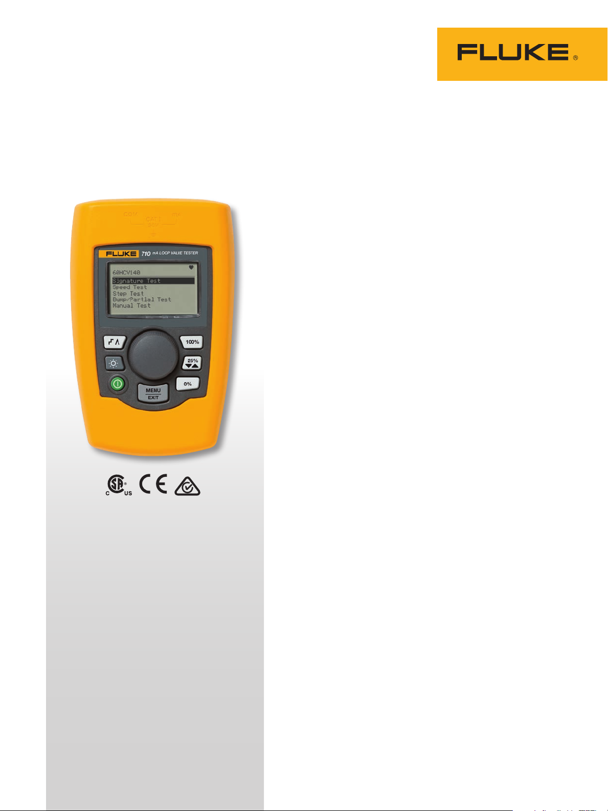
Fluke 710 mA Loop Valve Tester
Smart Control Valve Testing is now easier than ever
The Fluke 710 Valve Testing Loop Calibrator is designed to enable
users to perform quick, easy tests on HART smart control valves.
Featuring built-in test procedures and an intuitive user interface, the
710 allows users to quickly and easily perform valve tests, while the
valve test quick-check results provide at-a-glance diagnositcs help
you make maintenance decisions faster than ever. The valve health
quick-check results let you know whether your valve is in good,
marginal or in bad operating condition so you can quickly decide
whether additional maintenance is necessary.
Valve testing and HART communication in a precision
loop calibrator
With the 710 Valve Testing Loop Calibrator’s built in HART
communication function, users can source a 4-20 mA signal to cause
the smart control valve to move, while simultaneously interpreting
the valve’s HART feedback signal to determine whether the valve is
moving to the expected position. In addition to positional information,
the measured pressure delivered from the valve’s internal I/P (which
moves the valve) can be determined through the HART communication
protocol.
KEY VALVE TESTING FUNCTIONS
Valve signature test, speed test, step test,
manual test, bump/partial stroke test
KEY MA LOOP CALIBRATOR
FUNCTIONS
mA source, mA simulate, mA read, mA
read/loop power, and volts read
VALVETRACK™ SOFTWARE
Enables upload to a PC for further in-depth
analysis of valve measurements that are
logged and recorded to memory
The 710 has built-in test procedures that automatically increase
and change the mA signal while monitoring the HART position and
pressure feedback from the control valve, giving you a better overall
picture of valve health at the simple push of a button.
Pre-configured valve tests, at-a-glance answers
Valve test routines built into the 710 include:
• Manual testing; manually change the mA signal and view the
HART position and pressure variable information
• Full range ramping of the mA signal from 4 to 20 to 4 mA while
recording the 0-100-0% position, or the pressures applied that
move the valve from 0-100-0%
• Stepping the mA signal on the input to the valve in steps and
evaluating the valves response to the mA input changes
• Speed tests to determine how fast the valve can open or close
• Bump and partial stroke tests that help test valves over a portion
of their range so they can be tested in a live process
Page 2
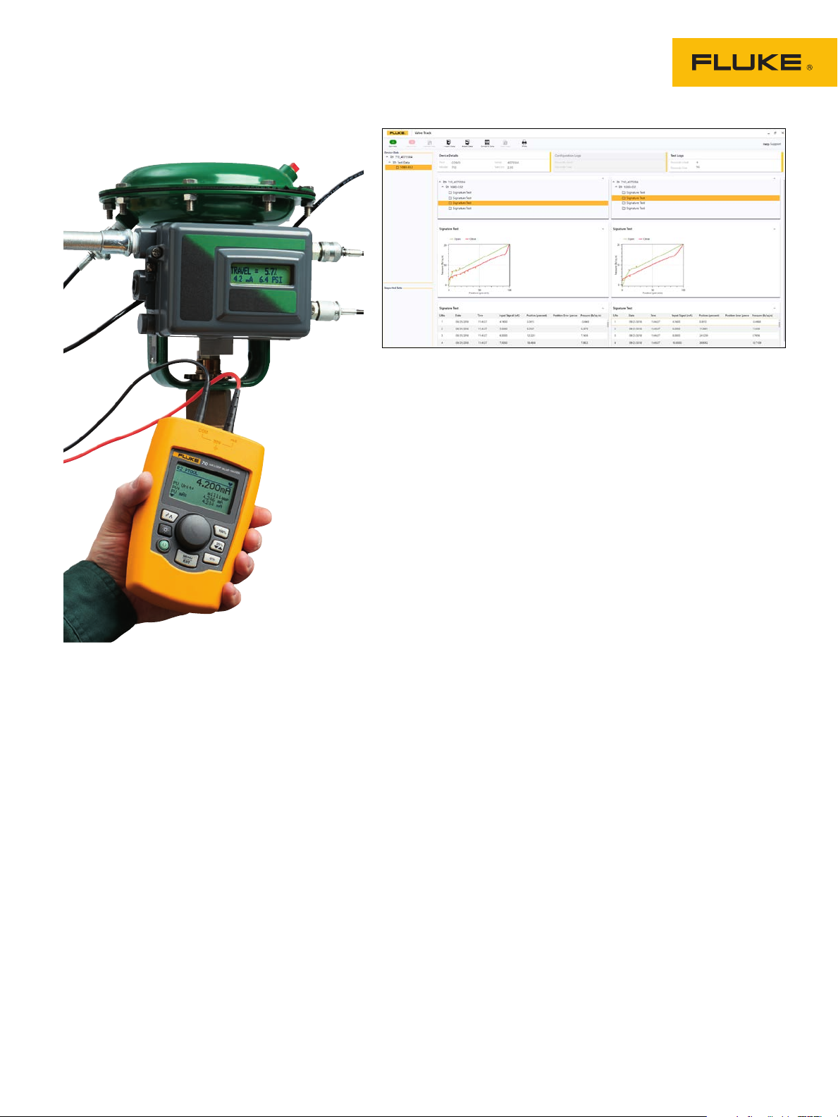
Performance test comparison in Fluke ValveTrack Software
ValveTrack™ Software enables further analysis and
trending
Valve tests that are logged and recorded to memory in the 710 are
available to upload to included ValveTrack™ analysis software.
ValveTrack™ software enables you to:
• Upload, print and plot logged valve tests taken in the field
• Compare previous uploaded tests to recent tests
• View valve test history by HART Tag ID
• Export valve test data to CSV for additional analysis in Microsoft
Excel®
Saving time, getting answers
In addition, the 710 offers:
• Logging of HART data in the field. Once recorded by the 710
in the field, the ValveTrack™ software can upload the HART
configuration of up to (20) HART devices in your plant and
output data in either (.csv) or (.txt) format.
• Data logged mA loop measurements and HART data can be
recorded from a particular transmitter for troubleshooting and
loop tuning. The data log feature offers selectable capture with
recording intervals of 1 to 60 seconds and a logging capacity of
9800 records or 99 individual sessions. Each record contains the
mA measurement and all four process variables.
2 Fluke Corporation Fluke 710 mA Loop Valve Tester
Page 3

Product Higlights
• Valve test procedures that deliver Good, Marginal or Bad assessment of a control valve
• Generic HART communication
• Best-in-class mA accuracy at 0.01 % measurement or source value
• Compact rugged design
• Intuitive user interface with Quick-Set knob for fast setup, easy to use
• 24 V DC loop power with mA measure mode (-25 % to 125 %)
• Resolution of 1 μA on mA ranges and 1 mV on voltages ranges
• Built in selectable 250 Ω resistor for HART communications
• Simple two wire connection for all measurements
• Auto shutdown to conserve battery life
• Variable step and ramp time in seconds.
Specifications
Features
Functions mA source, mA simulate, mA read, mA read/loop power, and volts read.
Ranges mA (0 to 24 mA) and Volts (0 to 30 V dc)
Resolution 1uA on mA ranges and 1mV on voltage range
Accuracy 0.01 % ± 2 counts all ranges (@ 23 °C ± 5 °C [73.4 °F ± 41 °F])
Operating temperature range -10 °C to 55 °C (14 °F to 131 °F)
Humidity range 10 to 95 % non-condensing
Stability 20 ppm of F.S./°C from -10 °C to 18 °C and 28 °C to 55 °C
Display 128 x 64 pixels, LCD graphic w/backlight, .34 in high digits
Power 6 AAA alkaline
Battery Life ≥ 40 hours continuous use (measure mode using alkaline)
Loop Compliance Voltage 24 V dc @ 20 mA
Voltage Protection 240 V ac
Overload Current Protection 28 mA dc
EMC EN61326 Annex A (portable instruments)
Dimensions (L x W x D) 15 cm x 9 cm x 3 cm (6 in x 3.6 in x 1.3 in)
Weight 0.3 kg (9.5 ounces)
Included Accessories
Warranty Three year
Traceable calibration certificate with data, batteries, test leads, USB upload cable and safety
manual
3 Fluke Corporation Fluke 710 mA Loop Valve Tester
Page 4

HART communication
Standard equipment
The Fluke 710 offers a built-in HART modem to communicate the
following HART commands:
• Read sensor PV information
• Read PV output information
• Read and write PV unit type, tag ID name, descriptor, and
message
• Read and write PV ranges (upper and lower)
• Enter/exit fixed current mode
• Set zero offset
• Trim DAC zero (mA output 4 mA)
• Trim DAC gain (mA output 20 mA)
HART Commands for Valves
The 710 includes these unique HART commands to support control
valves:
• Autotrim of valve controller
In addition, the Fluke 710 offers:
• Logging of HART data in the field. Once recorded by the 710
in the field, the ValveTrack™ software can upload the HART
configuration of up to 20 HART devices in your plant and output
data in either .csv or .txt format
• Data-logged mA loop measurements and HART data can be
recorded from a particular transmitter for troubleshooting and
loop tuning. The data log feature offers selectable capture with
recording intervals of 1 to 6 seconds and a logging capacity of
9800 records or 99 individual sessions. Each record contains the
mA measurement and all four process variables.
• Stackable test lead set
• Extended tooth alligator clip set
• TP220 test probes
• AC280 SureGrip™ hook clips
• Lemo to USB upload/download cable
• ValveTrack™ software (free download)
• Softcase
• Six AAA batteries (installed)
• 709/709H/710 Product manual CD-ROM
• 709/709H/710 Quick reference guide
• 709/709H/710 Safety information
Ordering information
Fluke-710 Valve Testing Loop Calibrator with HART
4 Fluke Corporation Fluke 710 mA Loop Valve Tester
Fluke. Keeping your world
up and running.
Fluke Corporation
PO Box 9090, Everett, WA 98206 U.S.A.
Fluke Europe B.V.
PO Box 1186, 5602 BD
Eindhoven, The Netherlands
For more information call:
In the U.S.A. (800) 443-5853 or
Fax (425) 446-5116
In Europe/M-East/Africa +31 (0) 40 2675 200 or
Fax +31 (0) 40 2675 222
In Canada (800)-36-FLUKE or
Fax (905) 890-6866
From other countries +1 (425) 446-5500 or
Fax +1 (425) 446-5116
Web access: http://www.fluke.com
©2018 Fluke Corporation.
Specifications subject to change without notice.
Printed in U.S.A. 6/2018 6011198a-en
Modification of this document is not permitted
without written permission from Fluke Corporation.
®
 Loading...