

Page 1

709/709H
Precision Loop Calibrator
Users Manual
January 2013
© 2013 Fluke Corporation. All rights reserved. Specifications are subject to change without notice.
All product names are trademarks of their respective companies.
Page 2

LIMITED WARRANTY AND LIMITATION OF LIABILITY
This Fluke product will be free from defects in material and workmanship for three years from the date of purchase. This
warranty does not cover fuses, disposable batteries, or damage from accident, neglect, misuse, alteration, contamination, or
abnormal conditions of operation or handling. Resellers are not authorized to extend any other warranty on Fluke’s behalf.
To obtain service during the warranty period, contact your nearest Fluke authorized service center to obtain return
authorization information, then send the product to that Service Center with a description of the problem.
THIS WARRANTY IS YOUR ONLY REMEDY. NO OTHER WARRANTIES, SUCH AS FITNESS FOR A PARTICULAR
PURPOSE, ARE EXPRESSED OR IMPLIED. FLUKE IS NOT LIABLE FOR ANY SPECIAL, INDIRECT, INCIDENTAL OR
CONSEQUENTIAL DAMAGES OR LOSSES, ARISING FROM ANY CAUSE OR THEORY. Since some states or countries
do not allow the exclusion or limitation of an implied warranty or of incidental or consequential damages, this limitation of
liability may not apply to you.
Fluke Corporation
P.O. Box 9090
Everett, WA 98206-9090
U.S.A.
11/99
Fluke Europe B.V.
P.O. Box 1186
5602 BD Eindhoven
The Netherlands
Page 3

Table of Contents
Title Page
Introduction .................................................................................................................... 1
How to Contact Fluke ..................................................................................................... 2
Safety Information .......................................................................................................... 3
Symbols ......................................................................................................................... 4
Standard Equipment....................................................................................................... 6
The Product .................................................................................................................... 8
The Buttons ............................................................................................................... 8
The Selection Knob ................................................................................................... 9
Main Menu ..................................................................................................................... 9
mA Source ................................................................................................................. 10
mA Simulate .............................................................................................................. 12
mA Measure .............................................................................................................. 13
mA Measure with 24V ............................................................................................... 14
Volts Measure ........................................................................................................... 15
Calibrator Setup Menu ................................................................................................... 16
i
Page 4

709/709H
Users Manual
Auto Ramp Time ....................................................................................................... 17
Auto Step Time ......................................................................................................... 17
Step and Ramp Operation ................................................................................... 18
Automatic Step and Ramp ................................................................................... 18
Valve Test ................................................................................................................. 19
HART 250Ω Resistor ................................................................................................ 20
mA Span ................................................................................................................... 20
Contrast .................................................................................................................... 21
Auto Shutdown Time ................................................................................................. 21
HART Write Enable ................................................................................................... 22
HART Device Communication ....................................................................................... 23
HART Connections ................................................................................................... 23
In Circuit, External Loop Power ............................................................................ 24
In Circuit, Product Loop Power ............................................................................. 25
Across Circuit, Communicator Only ..................................................................... 26
Communications Setup and Selection ...................................................................... 27
Mode .................................................................................................................... 28
250Ω Resistor ...................................................................................................... 28
HART Connect ..................................................................................................... 29
Polling Loop ......................................................................................................... 29
Tag Selection ....................................................................................................... 30
Acquiring Data ...................................................................................................... 30
Disconnect from Loop .......................................................................................... 31
Function Select Menu ............................................................................................... 31
Device Setup and Data ............................................................................................. 32
Write LRV and URV Values ........................................................................................... 33
Write LRV ................................................................................................................. 33
Write URV ................................................................................................................. 34
Trim, Set, and Zero Menu .............................................................................................. 34
ii
Page 5

Contents (continued)
Trim 4 mA .................................................................................................................. 35
Trim 20 mA ................................................................................................................ 36
Set Fixed mA Output ................................................................................................. 37
PV Zero ..................................................................................................................... 38
Device Diagnostic........................................................................................................... 39
Configuration Log and Data Log ................................................................................ 40
Configuration Log ................................................................................................. 40
Data Log ............................................................................................................... 42
Maintenance ................................................................................................................... 44
Clean the Product ...................................................................................................... 45
Fuse .......................................................................................................................... 45
Battery Replacement ................................................................................................. 46
User-Replaceable Parts ................................................................................................. 47
Specifications ................................................................................................................. 49
iii
Page 6

709/709H
Users Manual
iv
Page 7

List of Tables
Table Title Page
1. Symbols ................................................................................................................................. 4
2. Standard Equipment .............................................................................................................. 6
3. Buttons .................................................................................................................................. 8
4. User-Replaceable Parts ........................................................................................................ 47
v
Page 8

709/709H
Users Manual
vi
Page 9

List of Figures
Figure Title Page
1. Standard Equipment .............................................................................................................. 7
2. Buttons .................................................................................................................................. 8
3. Main Menu ............................................................................................................................. 9
4. mA Source Connections ........................................................................................................ 11
5. mA Simulate Connections ..................................................................................................... 12
6. mA Measure Connections ..................................................................................................... 13
7. mA Measure with 24 V Connections ..................................................................................... 14
8. Volts Measure Connections ................................................................................................... 15
9. Setup Menu, Screen 1 ........................................................................................................... 16
10. Setup Menu, Screen 2 ........................................................................................................... 16
11. Auto Ramp Time Screen ....................................................................................................... 17
12. Auto Ramp Step Time Screen ............................................................................................... 17
13. Valve Test Enable Screen ..................................................................................................... 19
14. HART Resistor Enable Screen .............................................................................................. 20
15. mA Span Selection Screen .................................................................................................... 20
vii
Page 10

709/709H
Users Manual
16. Contrast Adjustment Screen ................................................................................................. 21
17. Auto Shutdown Screen ......................................................................................................... 21
18. Hart Write Enable Screen ..................................................................................................... 22
19. Password Screen .................................................................................................................. 22
20. In Circuit, External Loop Power Connections ........................................................................ 24
21. In Circuit, 709H Loop Power ................................................................................................. 25
22. Across Circuit, Communicator Only Connections ................................................................. 26
23. HART Comm. Menu Screen ................................................................................................. 27
24. Mode Selection Screen ......................................................................................................... 28
25. 250Ω Resistor Screen ........................................................................................................... 28
26. Polling Screen ....................................................................................................................... 29
27. Tag Selection Screen............................................................................................................ 30
28. Acquiring Data Screen .......................................................................................................... 30
29. Disconnect from Loop Screen ............................................................................................... 31
30. Function Select Menu ........................................................................................................... 31
31. Sample Screen ..................................................................................................................... 32
32. Write LRV and URV Screen .................................................................................................. 33
33. Write LRV Screen ................................................................................................................. 33
34. Write URV Screen ................................................................................................................ 34
35. Trim, Set, and Zero Screen ................................................................................................... 34
36. Trim 4 mA Screen ................................................................................................................. 35
37. Trim 20 mA Screen ............................................................................................................... 36
38. Set Fixed mA Output Screen ................................................................................................ 37
39. PV Zero Screen .................................................................................................................... 38
40. Self Test Screen ................................................................................................................... 39
41. Self Test Results Screen ...................................................................................................... 39
42. Data Log and Configuration Log Screen ............................................................................... 40
43. Configuration Log Screen ..................................................................................................... 40
44. Configuration Log Showing Storage Position ........................................................................ 41
viii
Page 11

Contents (continued)
45. Data Log Screen ................................................................................................................... 42
46. Logging Interval Screen ........................................................................................................ 43
47. Active Logging Screen .......................................................................................................... 43
48. Battery Replacement ............................................................................................................. 46
ix
Page 12

709/709H
Users Manual
x
Page 13

Introduction
The Fluke 709 Precision Loop Calibrator and 709H
Precision HART Loop Calibrator (the Product or the
Calibrator) can be used for installation, calibration, and
troubleshooting of field transmitters, valves, and other
control system components at process plants. Primary
functions are source and measure mA signals in the 0 mA
to 24 mA range. The Product can also produce 24 V dc loop
power.
The 709H includes HART communication functionality and
supports a select set of HART universal and commonpractice commands. The Product can be used as a loop
calibrator or basic function communicator.
Product functions include:
• Current measurement, sourcing, and a selectable 24 V
supply
• 30 V dc measurement
• Valve test capability
• A selectable HART 250 Ω loop resistor
• Output step and ramp
1
Page 14

709/709H
Users Manual
Product features include:
• Large backlit display
• Digital selection knob with selectable decade control for
easy data entry
• Interactive menus
• Communicator mode reads basic device information,
does diagnostic tests, and can be used to trim the
calibration of most HART-enabled transmitters.
Note
All figures in this Manual show the 709H.
How to Contact Fluke
To contact Fluke, call one of the following telephone
numbers:
• Technical Support USA: 1-800-44-FLUKE
(1-800-443-5853)
• Calibration/Repair USA: 1-888-99-FLUKE
(1-888-993-5853)
• Canada: 1-800-36-FLUKE (1-800-363-5853)
• Europe: +31 402-675-200
• Japan: +81-3-6714-3114
• Singapore: +65-6799-5566
• Anywhere in the world: +1-425-446-5500
Or, visit Fluke's website at www.fluke.com.
To register your product, visit http://register.fluke.com.
To view, print, or download the latest manual supplement,
visit http://us.fluke.com/usen/support/manuals.
2
Page 15

Precision Loop Calibrator
Safety Information
Safety Information
A Warning identifies conditions and procedures that are
dangerous to the user. A Caution identifies conditions and
procedures that can cause damage to the Product or the
equipment under test.
Warning
To prevent possible electrical shock, fire, or
personal injury:
• Read all safety Information before you use
the Product.
• Use the Product only as specified, or the
protection supplied by the Product can be
compromised.
• Examine the case before you use the
Product. Look for cracks or missing
plastic. Carefully look at the insulation
around the terminals.
• Do not use test leads if they are damaged.
Examine the test leads for damaged
insulation and measure a known voltage.
• Do not use and disable the Product if it is
damaged.
• Do not use the Product around explosive
gas, vapor, or in damp or wet
environments.
• Do not touch voltages >30 V ac rms, 42 V ac
peak, or 60 V dc.
• Do not apply more than the rated voltage,
between the terminals or between each
terminal and earth ground.
• Do not connect directly to mains.
• Do not exceed the Measurement Category
(CAT) rating of the lowest rated individual
component of a Product, probe, or
accessory.
• Keep fingers behind the finger guards on
the probes.
• Remove all probes, test leads, and
accessories before the battery door is
opened.
• Remove the batteries if the Product is not
used for an extended period of time, or if
stored in temperatures above 50 °C. If the
batteries are not removed, battery leakage
can damage the Product.
• Replace the batteries when the low battery
indicator shows to prevent incorrect
measurements.
• The battery door must be closed and
locked before you operate the Product.
3
Page 16
709/709H
Users Manual
Symbols
Symbols used on the Product and in this manual are explained in Table 1.
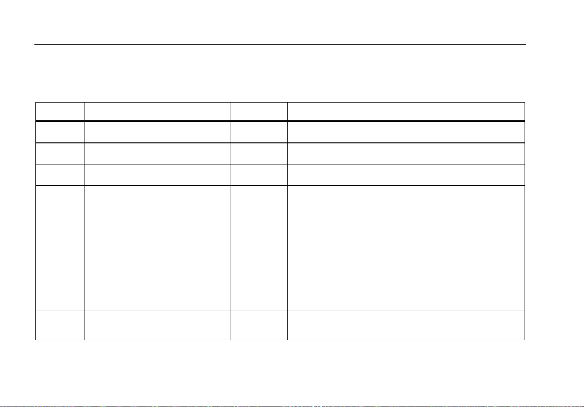
Table 1. Symbols
Symbol Meaning Symbol Meaning
4
Earth ground
AC- alternating current
DC- direct current
Risk of danger. Important
information. See manual.
Hazardous voltage. Risk of
electrical shock.
Conforms to relevant North American Safety Standards.
Conforms to European Union directives.
Conforms to relevant Australian standards.
This product complies with the WEEE Directive
(2002/96/EC) marking requirements. The affixed label
indicates that you must not discard this
electrical/electronic product in domestic household
waste. Product Category: With reference to the
equipment types in the WEEE Directive Annex I, this
product is classed as category 9 "Monitoring and
Control Instrumentation” product. Do not dispose of this
product as unsorted municipal waste. Go to Fluke’s
website for recycling information.
Examined and licensed by TÜV Product Services.
Page 17
Precision Loop Calibrator
Symbols
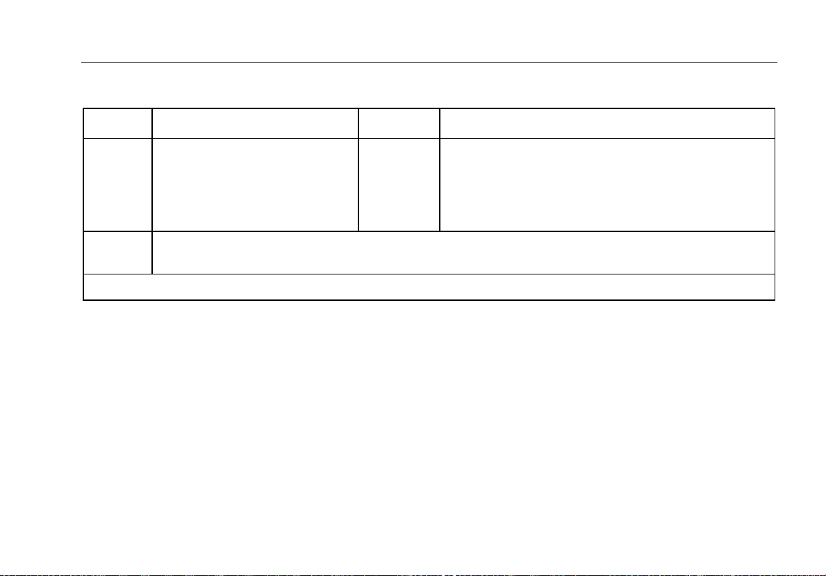
Table 1. Symbols (cont.)
CAT II
CAT IV
The CAT ratings apply to the handheld accessories only. The Product is rated to 30 V maximum.
Battery.
Measurement Category II is
applicable to test and measuring
circuits connected directly to
utilization points of low voltage
mains installation.
Measurement Category IV is applicable to test and measuring circuits connected at the source of the
building’s low-voltage MAINS installation.
CAT III
Double insulated
Measurement Category III is applicable to test and
measuring circuits connected to the distribution part of
the building’s low-voltage MAINS installation.
5
Page 18
709/709H
Users Manual
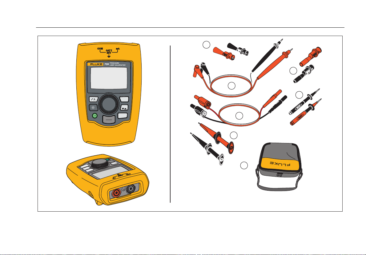
Standard Equipment
Items included with the Product are listed in Table 2 and shown in Figure 1.
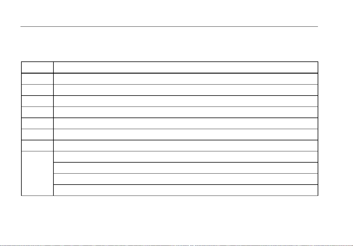
Table 2. Standard Equipment
Item Description
Two AC72-1 alligator clips (709)
TL-75-4201 test leads (709)
754-8016 alligator clip set (709H)
75X-8014 stackable lead set (709H)
TP220-4201 test probes (709H)
AC280-5001 Suregrip hook clips (709H)
Soft Case
Six AAA batteries (installed)
Not Shown
6
709/709H Product Manual CD-ROM
709/709H Quick Reference Guide
709/709H Safety Information
Page 19
Precision Loop Calibrator
Standard Equipment
1
3
2
5
MENU
100%
25%
0%
EXIT
4
6
7
gzx002.eps
Figure 1. Standard Equipment
7
Page 20

709/709H
Users Manual
The Product
The subsequent sections are about the features and
functions of the Product.
The Buttons
Figure 2 and Table 3 show the location and brief
descriptions of the Product buttons.
Table 3. Buttons
Button Function
Push to enable step or ramp.
Push to turn on or turn off the backlight.
gzx001.eps
Figure 2. Buttons
8
Push to turn on and turn off the Product.
Push to set the output to 20 mA when in mA
Source or mA Simulate modes. In
Measurement mode the button does not set
the output current.
Push to step the output up or down by 25 %
increments (4, 8, 12, 16, 20 mA).
Push to set the output to 4 mA when in
mA Source or mA Simulate mode. In
Measurement mode the button does not set
the output current
Push to enter the Main menu. Push a
second time to exit the Main menu. See the
“Main Menu” section.
Page 21

Precision Loop Calibrator
The Product
The Selection Knob
The selection knob lets you select and control necessary
functions and navigate through the Product menus. Turn
the selection knob to highlight a menu item or adjust a
value. When the necessary selection is highlighted, push
the selection knob to do the selected action, or push and
hold to save any changes that have been made. Push
to go to the main screen with no action.
In the output modes (mA Source, mA Simulate):
• Push the selection knob to move the display cursor
to the next digit.
• Turn the selection knob to increment or decrement
the output in steps shown by the selected decade.
• Push , , or to set the output to preset
values.
• Push to select and stop these advanced modes.
Main Menu
Push to show the Main menu, choose the primary
operation mode of the Product, access the Product setup
menu, or to use HART mode. See Figure 3.
gzx20.eps
Figure 3. Main Menu
The first five items shown on the Main menu change the
Product operation mode accordingly and once selected,
change the Product menu to a “home” screen for the
selected function. The operation modes are explained in
the subsequent sections of this manual.
For the last two items of the Main menu, see “The
Calibrator Setup Menu” and “Hart Comm. Menu” sections.
Note
The “HART” menu items only apply to the 709H.
9
Page 22

709/709H
Users Manual
Note
Some menus have multiple screens. When this
is the case, the lower-left corner of the menu
shows when additional screens follow the
current screen. is shown when additional
screens precede the current screen. Both icons
are shown when additional screens follow and
precede the present screen.
mA Source
In the mA Source mode, the Product outputs a signal
from 0 mA to 24 mA into a load of up to 1000 Ω (750 Ω if
the internal HART resistor is switched on).
Figure 4 shows the mA Source home screen and typical
connections for this mode.
10
Page 23

Precision Loop Calibrator
The Product
To use mA Source:
1. Select mA Source from the Main menu.
2. Push the selection knob to move the decade cursor.
3. Turn the selection knob to increment or decrement
the output in steps indicated by the selected decade.
4. Push , , or to set the output to preset
values.
5. Push to select and stop these advanced modes.
When automatic step or ramp is active, one of the
subsequent icons is shown in the lower left corner:
Automatic step:
Automatic ramp:
6. Push to go to the Main menu.
7. Push again to go to the mA Source home
screen.
• Valve Test is shown in the lower center when
the valve test function has been enabled on the
Setup menu. See the “Valve Test” section of this
manual.
• 250Ω is shown in the lower right corner when
the HART resistor has been enabled on the
setup menu.
4 mA to 20 mA
Input Device,
Recorder/Indicator,
etc.
4 mA to 20 mA
gzx003.eps
Figure 4. mA Source Connections
11
Page 24

709/709H
Users Manual
mA Simulate
In the mA Simulate mode, the Product functions like a
2-wire transmitter and controls the loop current from an
external power supply. This function can test a loop
with the transmitter removed.
Figure 5 shows the mA Simulate home screen and typical
connections for this mode.
To use mA Simulate:
1. Select mA Simulate from the Main menu.
2. Push the selection knob to move the decade cursor.
3. Turn the selection knob to increment or decrement
the output in steps indicated by the selected decade.
4. Push , , or to set the output to preset
values.
5. Push to select and stop these advanced modes.
When automatic step or ramp is active, one of the
subsequent icons is shown in the lower left corner:
• Automatic step:
• Automatic ramp:
6. Push to go to the Main menu.
7. Push again to go to the mA Simulate home
screen.
• Valve Test is shown in the lower center when
the valve test function has been enabled on the
Setup menu. See the “Valve Test” section of this
manual.
• 250Ω is shown in the lower right corner when
the HART resistor has been enabled on the
setup menu.
Power Supply
30 V dc Max
4 mA to 20 mA
4 mA-20 mA
Input Device
gzx004.eps
Figure 5. mA Simulate Connections
12
Page 25

Precision Loop Calibrator
The Product
mA Measure
In the mA Measure mode, the Product shows the loop
current measurement. This mode is without 24 V.
Figure 6 shows the mA Measure home screen and typical
connections for this mode.
To use mA Measure:
Select mA Measure from the Main menu. Once selected,
the Product changes to the mA Measure home screen.
250Ω is shown in the lower right corner when the HART
resistor has been enabled on the setup menu.
4 mA-20 mA
Output Device
4 mA to 20 mA
Figure 6. mA Measure Connections
gzx005.eps
13
Page 26

709/709H
Users Manual
mA Measure with 24V
In the mA Measure with 24V mode, the Product outputs
24 V dc as it shows the loop current. The mode can
power a transmitter without a separate power supply.
Figure 7. mA Measure with 24 V Connections
Figure 7 shows the home screen and typical connections
for this mode.
gzx006.eps
14
Page 27

Precision Loop Calibrator
The Product
To use mA Measure with 24 V:
1. Select mA Measure with 24 V from the Main menu.
Once selected, the Product changes to the mA
Measure with 24 V home screen.
Voltage
Output Device
250Ω is shown in the lower right corner when the HART
resistor has been enabled on the setup menu.
Volts Measure
In the Volts Measure mode, the Product shows the loop
voltage. Figure 8 shows the Volts Measure home screen
and typical connections for this mode.
To use the Volts Measure mode:
Select Volts Measure from the Main menu. Once
selected, the Product changes to the Volts Measure
home screen.
gzx007.eps
Figure 8. Volts Measure Connections
15
Page 28

709/709H
Users Manual
Calibrator Setup Menu
The Calibrator Setup Menu has two screens. To go to
the second screen, select Other Parameters from the
first screen. Screen 1 is shown in Figure 9 and screen 2
is shown in Figure 10.
gzx21.eps
Figure 9. Setup Menu, Screen 1
Figure 10. Setup Menu, Screen 2
Note
The “HART Write Enable” menu item only is
shown on the 709H.
gzx22.eps
16
Page 29

Precision Loop Calibrator
Calibrator Setup Menu
Auto Ramp Time
The Auto Ramp Time function sets the full-scale ramp
time for the mA ramp feature. The value can be set from
5 seconds to 300 seconds. Push the selection knob to
move the decade cursor. Turn the selection knob to
adjust the value in steps indicated by the decade
selected. See Figure 11.
gzx23.eps
Figure 11. Auto Ramp Time Screen
Auto Step Time
The Auto Step Time function sets the step interval time
for the mA Auto Step feature. The value can be set from
5 seconds to 300 seconds. Push the selection knob to
move the decade cursor. Turn the selection knob to
adjust the value in steps indicated by the decade
selected. See Figure 12.
gzx24.eps
Figure 12. Auto Ramp Step Time Screen
17
Page 30

709/709H
Users Manual
Step and Ramp Operation
For step and ramp operation, the percent keys can be
used to set the milliamp output to 0 % of span, 100 % of
span, or step the output by 25 % of span.
Hands-free operation is possible with . Set the
Product to automatically and continuously step or ramp
the milliamp output from 0 % to 100 % and back.
The 100 % value is always 20 mA, but the 0 % value can
be 0 mA or 4 mA. This depends on how the mA span is
set. The 25 % step size is 5 mA or 4 mA accordingly.
To use the manual step function:
1. Use the Main menu to set the Product to source or
simulate current.
2. Push to set the output to 0 % of span.
3. Push to set the output to 100 % of span.
4. Push to step the output in 25 % of span
increments, from 0 % of span to 100 % of span and
back.
Automatic Step and Ramp
To use the automatic step and automatic ramp functions:
1. Use the Main menu to set the Product to source or
simulate current.
2. The Product has separate auto ramp and step times.
Use the menu to set the ramp or step time.
3. Push once to continually step the output from
0 % of span to 100 % of span and back in increments
of 25 % of span at the specified interval.
4. Push once more to go to auto ramp.
5. Push one of the percent keys, and twice, to turn
off the auto step and ramp.
6. Push twice to continually ramp the output from
0 % of span to 100 % of span over the specified
interval, and then back over the specified interval.
7. Push one of the percent keys or once more, to
turn off the auto step and ramp.
18
Page 31

Precision Loop Calibrator
Calibrator Setup Menu
Valve Test
The Valve Test function turns on or off the valve test
feature. See Figure 13.
Figure 13. Valve Test Enable Screen
gzx25.eps
The valve test verifies correct operation of valves. In
valve test, the output can be stepped to these values:
• 3.8 mA
• 4.0 mA
• 4.2 mA
• 8.0 mA
• 12.0 mA
• 16.0 mA
• 19.8 mA
• 20.0 mA
• 20.2 mA
The valve test mA values are not affected by the mA span
setting.
1. Use the Main menu to set the Product to source or
simulate current.
2. If valve test is not enabled, use the menu to enable it.
3. Push or to step the output to verify the
proper valve operation.
4. Use the menu to disable valve test when done.
19
Page 32

709/709H
Users Manual
HART 250Ω Resistor
The HART 250Ω Resistor Enable function turns on and
turns off the HART resistor. See the “HART Resistor”
section of this manual. See Figure 14.
gzx26.eps
Figure 14. HART Resistor Enable Screen
The Product can insert a 250 Ω resistor in series with the
power supply in order to use a HART communicator. The
HART resistor is enabled through the menu.
To get to the second Calibrator Setup Screen, highlight
Other Parameters and push the selection knob.
mA Span
mA Span is the first item on the second Calibrator Setup
Menu.
The mA Span function sets the step interval for the mA
Auto Step feature. The value can be set from 5 seconds
to 300 seconds. See the “Step and Ramp Operation”
section of this manual. See Figure 15.
gzx27.eps
Figure 15. mA Span Selection Screen
20
Page 33

Precision Loop Calibrator
Calibrator Setup Menu
Contrast
The Contrast function adjusts the display contrast. Turn
the selection knob to adjust the contrast. The range is
shown by the bar graph. Higher contrast is shown by a
longer bar. The sample normal and reverse video
selections let you evaluate both text modes. See
Figure 16.
gzx28.eps
Figure 16. Contrast Adjustment Screen
Auto Shutdown Time
The Auto Shutdown Time function sets or turns off the
time before the Product automatically shuts itself down if
the keypad is not used. The value can be set to
Disabled, or from 1 minute to 30 minutes. See Figure 17.
gzx29.eps
Figure 17. Auto Shutdown Screen
21
Page 34

709/709H
Users Manual
HART Write Enable
HART Write Enable is the last function in the Calibrator
Setup Menu. See Figure 18.
gzx30.eps
Figure 18. Hart Write Enable Screen
This function is available only on the 709H. It protects the
Write LRV, Write URV, Device Diagnostic, Trim 4mA,
Trim 20mA, Set Fixed Output, and PV Zero functions.
The default setting is ON, but it may be turned off to
protect the Product against unauthorized use.
Before the setting is changed, a password is required.
The password is set to 617 at the factory. The range of
values that can be set is 000 to 999. See Figure 19.
The write-enable selection is saved only when the correct
password is given. Otherwise an error message is shown.
Push the selection knob to move the decade cursor. Turn
the selection knob to adjust the value in steps indicated
by the decade selected. Push and hold the selection knob
to save the write enable setting. Push to restore the
previous HART-enable selection and go to the Main
screen.
gzx31.eps
Figure 19. Password Screen
22
Page 35

Precision Loop Calibrator
HART Device Communication
HART Device Communication
The HART functions are only available in the 709H.
Auto shutdown is disabled when the HART menus are
used. Auto shutdown is restored to its previous state
when you exit the HART menus.
Note
Loop current trim is supported for transmitter
devices, but is not supported for actuator
devices.
These functions can be disabled with the HART Write
Enable selection on the Product:
• write LRV
• write URV
• device diagnostic
• trim 4 mA
• trim 20 mA
• fixed output
PV zero functions can be disabled with the HART Write
Enable selection on the Calibrator Setup menu. See the
“Calibrator Setup Menu” section of this manual. If these
functions are necessary, they must be enabled before
you enter the HART menus.
HART Connections
See the subsequent sections for HART connections.
23
Page 36

709/709H
Users Manual
In Circuit, External Loop Power
In mA Measure mode, the Product is in circuit and loop
power is supplied externally. In Figure 20, the 250 Ω
24 V
Supply
Figure 20. In Circuit, External Loop Power Connections
4 mA to 20 mA
HART resistor is enabled. If the loop already has 250 Ω,
do not enable the HART resistor.
gzx008.eps
24
Page 37

Precision Loop Calibrator
HART Device Communication
In Circuit, Product Loop Power
In mA Measure with 24V mode, the Product is in circuit
and loop power is supplied by the Product. In Figure 21,
Figure 21. In Circuit, 709H Loop Power
the 250 Ω HART resistor is enabled. If the loop already
has 250 Ω, do not enable the HART resistor.
gzx009.eps
25
Page 38

709/709H
Users Manual
Across Circuit, Communicator Only
In Communicator Only mode, the Product is across the
circuit and loop power is supplied externally. In Figure 22,
24 V
Supply
4 mA to 20 mA
Figure 22. Across Circuit, Communicator Only Connections
26
when in Communicator Only mode, there must be 250 Ω,
resistance present in the loop.
RL ≥ 250 Ω
gzx010.eps
Page 39

Precision Loop Calibrator
HART Device Communication
Communications Setup and Selection
For all Main screen operation modes, except mA
Measure with 24V or Volts Measure, the operation
mode is set to mA Measure when you enter the HART
Comm. Menu.
The operation mode remains the same as the main
screen when it is Measure with 24V. If Volts Measure
was selected from the Main menu, the menu defaults to
communicator mode only and the 250 Ω resistor selection
shows n/a.
The 250 Ω resistor selection cannot be edited in
communicator mode.
The mode and resistor will change from the last
selections made in the HART Comm. Menu when you
exit the menu.
The mode and 250 Ω resistor settings must correspond to
how the test leads are connected before you connect.
See Figure 23.
Figure 23. HART Comm. Menu Screen
Select a function from the menu and push the selection
knob to do the function. Push to disconnect from
HART mode and go to the function home screen without
action.
An error is shown and no action is taken if the measured
input is out of range, OL or -OL.
250Ω Resistor, and HART CONNECT functions are
described in subsequent sections.
gzx32.eps
27
Page 40

709/709H
Users Manual
Mode
The Mode function from the HART. Comm. Menu lets
you select what mode to work in. See Figure 24.
gzx33.eps
Figure 24. Mode Selection Screen
Use the selection knob to choose the necessary mode:
• mA Measure- The Product is in circuit and loop
power is supplied externally.
• mA Measure with 24V- The Product is in circuit and
the loop power is supplied by the Product.
• Communicator Only- The Product is across the
circuit and the loop power is supplied externally. The
250Ω resistor selection defaults to n/a (not
applicable).
250Ω Resistor
The 250Ω Resistor function lets you turn the 250 Ω
resistor on or off. Use the selection knob to change the
resistor to the highlighted selection and return to the
Setup and Selection screen. See Figure 25.
gzx34.eps
Figure 25. 250Ω Resistor Screen
28
Page 41

Precision Loop Calibrator
HART Device Communication
HART Connect
The HART Connect function locates the HART device in
the loop. Before an operation with a HART device, the
device must be located on the loop. This is done by
polling all of the possible device addresses and selecting
a device from those addresses that respond to the
search.
If a HART protocol revision 5 or earlier device is found on
the loop, polling stops at poll address 15. If not found, the
Product continues to poll address 63. Polling stops after
10 devices are found on the loop.
If multiple devices are found on the loop, a tag list is
shown. From the list, select the correct device. If only one
device is found on the loop, it becomes the selected
device by default.
When a selected device is found, all relevant data is read
from the device and the operations described in the
“Function Select Menu” and “Device Setup and Data”
sections of this manual become available.
Polling Loop
The Polling Loop function searches the loop for HART
devices. This function starts immediately. The screen
changes to show the string of dots that is extended once
per second to as the operation progresses. See
Figure 26.
Figure 26. Polling Screen
The number of devices found on the loop during polling is
shown.
The selection knob can be pushed to stop polling early if
it is known that all of the devices on the loop have been
found. Push to stop polling, disconnect from HART
mode, and go to the function home screen.
An error is shown if no device is found.
If multiple devices are found, a list of tags is shown. Use
the list of tags to select the necessary device.
If only one device is found, the tag selection step is
skipped.
gzx35.eps
29
Page 42

709/709H
Users Manual
Tag Selection
The tag selection screen lists all of the long tag names
found during polling. Tag names can span two lines if
necessary to show all of the text.
If the long tag name is not available, or it is blank, a short
tag name is used. If the short tag name is blank, the text
Poll address x is used.
Use the selection knob to go to the necessary tag. See
Figure 27.
gzx36.eps
Figure 27. Tag Selection Screen
Acquiring Data
The Acquiring Data screen is shown while the Product
acquires all of the configuration data from the device. The
string of dots extends once per second to show the
operation progress. flashes in the upper-right corner to
show a live HART connection.
The screen in Figure 28 shows the name of the tag that is
accessed.
gzx37.eps
Figure 28. Acquiring Data Screen
Push to stop data acquisition, disconnect from HART
mode, and go to the function home screen.
When data acquisition is complete, the Function Select
Menu is shown.
30
Page 43

Precision Loop Calibrator
HART Device Communication
Disconnect from Loop
The Disconnect from Loop screen is shown before the
Product returns to the function home screen so the
Product can be disconnected from the Loop. See
Figure 29 .
gzx38.eps
Figure 29. Disconnect from Loop Screen
Function Select Menu
The Function Select menu is shown in Figure 30.
gzx39.eps
Figure 30. Function Select Menu
The tag name is truncated to fit on one line when
necessary. flashes in the upper-right corner to show a
live connection.
Use the selection knob to choose the necessary action.
Push to disconnect from HART mode and go to the
function main screen.
31
Page 44

709/709H
Users Manual
Device Setup and Data
The Device Setup and Data screen spans 11 screens
with the format shown in Figure 31.
gzx40.eps
Figure 31. Sample Screen
This screen shows all of the data retrieved from the data
acquisition procedure.
The tag name is truncated to fit on one line when
necessary. flashes in the upper-right corner to show a
live connection.
Each screen holds a maximum of 6 data points. An item
can span more than one line when necessary to show the
full text. If a data item is not supported in the HART
device, it is marked n/a (not available). Data items that
change dynamically in the HART device are updated as
often as possible on the screens.
Turn the selection knob to go from screen to screen.
Push to go to the Function Select menu.
32
Page 45

Precision Loop Calibrator
Write LRV and URV Values
Write LRV and URV Values
Note
For the screens in this section, tag names can
be truncated to fit on one line if necessary.
flashes in the upper-right corner to show a live
connection.
If the HART write commands are not active, these
functions are not available and an error message is
shown instead of the screen in Figure 32.
gzx41.eps
Figure 32. Write LRV and URV Screen
Use the selection knob to choose the necessary function.
Push the selection knob to choose the highlighted action
and go to the corresponding screen. These screens are
explained in the “Write LRV” and “Write URV” sections.
Push to go to the Function Select menu.
Write LRV
The Product warns you to change the loop to MANUAL
before you proceed. Push the selection knob to proceed.
Push to go to the Write LRV and Write URV menu.
The present LRV value and units are shown. See
Figure 33.
gzx42.eps
Figure 33. Write LRV Screen
1. Push the selection knob to move the decade cursor.
2. Turn the selection knob to increment or decrement
the value in steps indicated by the selected decade.
3. Push and hold the knob to send the new value to the
HART device. An error is shown if the HART device
rejects the value.
33
Page 46

709/709H
Users Manual
4. Push to go to the Function Select menu. A
reminder to change the loop to AUTOMATIC is
shown first.
Write URV
The Product warns you to change the loop to MANUAL
before you proceed. Push the selection knob to proceed.
Push to go to the LRV and URV menu.
The present URV value and units are shown. See
Figure 34.
gzx43.eps
Figure 34. Write URV Screen
1. Push the selection knob to move the decade cursor.
2. Turn the selection knob to increment or decrement
the value in steps indicated by the selected decade.
3. Push and hold the knob to send the new value to the
HART device, remaining on this display. An error is
shown if the HART device rejects the value.
4. Push to go to the LRV and URV menu. A prompt
to change the loop to AUTOMATIC is shown first.
Trim, Set, and Zero Menu
Note
For the screens in this section, tag names can
be truncated to fit on one line if necessary.
flashes in the upper-right corner to show a live
connection.
If the HART write commands are not enabled, these
functions are not available and an error message is
shown instead of the screen shown in Figure 35.
gzx44.eps
Figure 35. Trim, Set, and Zero Screen
34
Page 47

Precision Loop Calibrator
Trim, Set, and Zero Menu
Use the selection knob to select and start the necessary
action. Push to go to the Function Select menu.
Trim 4 mA
If the operation mode is Communicator Only, this
function is not available and an error message is shown.
A prompt to change the loop to MANUAL before you
proceed is shown. Push the selection knob to proceed.
Push to go to the Trim, Set and Zero menu.
While the HART device is changed to fixed output mode,
An error is shown if the HART device rejects the mode
change command. When the mode change is successful,
the screen in Figure 36 is shown.
gzx45.eps
Figure 36. Trim 4 mA Screen
While the output to settles at 4 mA, the screen shows the
Product measurement. The measurement is updated
once a second.
1. Push the selection knob to trim the HART device.
Stay on this screen to evaluate the result. An error is
shown if the HART device rejects the trim command.
2. Push to change the HART device to normal
output mode and go to the Trim, Set, and Zero menu.
A warning to change the loop to AUTOMATIC is
shown first. An error is shown if the device rejects the
mode change command.
35
Page 48

709/709H
Users Manual
Trim 20 mA
If the operation mode is Communicator Only, this
function is not available and an error message is shown.
A warning to change the loop to MANUAL before you
proceed is shown. Push the selection knob to proceed.
Push to go to the Trim, Set and Zero menu.
While the HART device is changed to fixed output mode,
an error is shown if the HART device rejects the mode
change command. When the mode change is successful,
the screen in Figure 37 is shown.
gzx46.eps
Figure 37. Trim 20 mA Screen
As the output to settles at 20 mA, the screen shows the
Product measurement. The measurement is updated
once a second.
1. Push the selection knob to trim the HART device.
Stay on this screen to evaluate the result. An error is
shown if the HART device rejects the trim command.
2. Push to change the HART device to normal
output mode and go to the Trim, Set, and Zero menu.
A prompt to change the loop to AUTOMATIC is
shown first. An error is shown if the device rejects the
mode change command.
36
Page 49

Precision Loop Calibrator
Trim, Set, and Zero Menu
Set Fixed mA Output
If the operation mode is Communicator Only, this
function is not available and an error message is shown.
A warning to change the loop to MANUAL before you
proceed is shown. Push the selection knob to proceed.
Push to go to the Trim, Set and Zero menu.
As the HART device is changed to fixed output mode, an
information screen is shown. An error is shown if the
HART device rejects the mode change command. When
the mode change is successful, the screen in Figure 38 is
shown.
gzx47.eps
Figure 38. Set Fixed mA Output Screen
This screen is used to set a fixed output and monitor the
result with the Product measurement. The measurement
is updated once a second.
The range of values that can be set is 3.0 mA to 21.0 mA.
1. Use the selection knob to select and increment or
decrement the value in steps shown by the selected
decade.
2. Push and hold the selection knob to send the new
value to the HART device and stay on this screen.
An error is shown if the HART device rejects the
value.
3. Push to change the HART device to normal
output mode and go to the Trim, Set, and Zero menu.
A warning to change the loop to AUTOMATIC is
shown first. An error is shown if the device rejects the
mode change command.
37
Page 50

709/709H
Users Manual
PV Zero
A warning to change the loop to MANUAL before you
proceed is shown. Push the selection knob to proceed.
Push to go to the Trim, Set, and Zero menus.
The screen shown in Figure 39 prompts you to set the PV
process input signal to zero and then monitors the result
with the Product measurement. The measurement is
updated once a second.
When the operation mode is Communicator Only, the
mA measurement is not available and the message mA
not available, in Comm. Only mode is shown instead.
gzx48.eps
Figure 39. PV Zero Screen
1. Push the selection knob to zero the HART device,
and stay on this screen to evaluate the result. An
error is shown if the HART device rejects the zero
command.
2. Push to go to the Trim, Set, and Zero menu. A
prompt to restore the PV process input signal to
normal operation configuration and change the loop
to AUTOMATIC is shown first.
38
Page 51

Precision Loop Calibrator
Device Diagnostic
Device Diagnostic
Note
For the screens in this section, tag names can
be truncated to fit on one line if necessary.
flashes in the upper-right corner to show a live
connection.
If the HART write commands are not active, this function
is not available and an error message is shown.
A warning to change the loop to MANUAL before you
proceed is shown. Push the selection knob to proceed.
Push to go to the Function Select menu.
Push the selection knob to select and start the self test.
See Figure 40.
gzx49.eps
Figure 40. Self Test Screen
As the self test is done, the bottom line of the screen
changes to Testing and a string of dots extends once per
second to show the operation progress.
At the end of the self test, the screen in Figure 41 is
shown. It shows No errors or the first error is reported.
gzx50.eps
Figure 41. Self Test Results Screen
The lower-left corner shows when additional errors
follow the present error. is shown when additional
errors precede the present error. and show when
additional errors follow and precede the present error.
39
Page 52

709/709H
Users Manual
Turn the selection knob to step between errors.
1. Push to go to the Function Select menu. A
reminder to change the loop to AUTOMATIC is
shown first.
Configuration Log and Data Log
Configuration Log and Data Log are only available when
connected to a HART device. Use the selection knob to
choose either the Configuration Log or Data Log. See
Figure 42.
gzx51.eps
Figure 42. Data Log and Configuration Log Screen
Configuration Log
Configuration data for a maximum of 20 tags can be
stored for later recall. The configuration data saved is the
same as that shown on the Device Data screen.
The initial Configuration Log screen spans more than one
screen and shows a list of the tags held in storage. If a
storage position is not used, the tag name area shows
<empty>. See Figure 43.
gzx52.eps
Figure 43. Configuration Log Screen
After a storage position is selected, data can be saved or
recalled from it. It can be erased or sent to the USB port.
The data can also be uploaded to a PC with the
709H/TRACK Windows Software.
40
Page 53

Precision Loop Calibrator
Device Diagnostic
It is recommended that you use a Lemo to USB cable
with 709H/TRACK Software. It has a USB/Serial adapter
that uses an FTDI chipset. This combination gives
consistent and reliable communication between the
Product and PC. The USB Drivers are included on the
709H/TRACK Software CD.
Use the selection knob to highlight and select the correct
storage location.
Push to go to the Log Select menu.
When a storage position is selected, the menu in
Figure 44 is shown. Select the necessary action.
gzx53.eps
Figure 44. Configuration Log Showing Storage
Position
The number and contents of the storage position are
shown at the top. The tag number is <empty> if the
storage position is empty.
Use the selection knob to highlight and select the correct
function. Push to go to the Log Select menu.
SAVE operation:
• If the position is empty, save the present device
configuration data into the storage position.
• If the position is in use, confirm that the existing data
is to be replaced with the present tag data before you
save it into the storage position.
RECALL operation:
• If the position is empty, an error message is shown.
• If the position is in use, the data is shown in a
sequence of screens identical to the Device Data
screen.
ERASE operation:
• If the position is empty, an error message is shown.
• If the position is in use, confirm that the existing data
is to be permanently deleted before doing so.
41
Page 54

709/709H
Users Manual
SEND operation:
• If the position is empty, an error message is shown.
• If the position is in use, send the data to the RS232
port in a report format.
Data Log
Process data can be stored for a single tag for later
upload to a PC with the 709H/TRACK Windows Software.
See the “Configuration Log” section of this manual for
more.
Data can be logged in multiple sessions, but all sessions
must be from the same HART device as determined by
the long tag name. A different logging interval can be
selected for each session. Each data sample has the
Product measurement, device mA, and all four process
variables.
There are 9810 records available. Each data sample uses
one record. Each session uses two records for overhead
data that is common to all of the data samples in that
session. There can be from 1 to 99 sessions.
The total number of data samples that can be logged is
9810 less 2 times the number of sessions started and
stopped. See Figure 45.
gzx54.eps
Figure 45. Data Log Screen
The number of free records is shown on the first line. If
data has already been logged, the tag number is shown
below it.
The present battery voltage is shown at the bottom so
that you can tell if the batteries should be changed before
a log session starts. The log is stopped before the
Product is turned off when the battery reaches its low
voltage automatic shutoff limit of 5.6 V.
• Use the selection knob to highlight and select the
correct function.
• Push the knob to do the operation. Push to
return to the Log Select menu.
42
Page 55

Precision Loop Calibrator
Device Diagnostic
START operation:
• If no free records or free sessions remain, or the
present HART device does not match the HART
device already logged, an error message is shown.
• Otherwise, proceed to interval selection described
below.
ERASE operation:
• If there is no logged data, an error message is
shown.
• Otherwise, confirm that the present data is to be
permanently erased before doing so.
Select the logging interval. See Figure 46.
gzx55.eps
Figure 46. Logging Interval Screen
Turn the selection knob to move the highlight and select
the necessary interval. Push the selection knob to start
logging at that interval. Push to go to the first data log
screen.
While logging, the screen in Figure 47 is shown to
monitor progress.
gzx56.eps
Figure 47. Active Logging Screen
Push to stop logging and go to the first data log
screen.
43
Page 56

709/709H
Users Manual
The data items shown are:
• The top line indicates is logging is in progress
(Logging) or is stopped (Stopped). Logging stops
automatically when storage is full or before the
Product is turned off when the battery reaches its low
voltage automatic shutoff limit of 5.6 V.
• Interval is the item previously selected.
• Elapsed is the time since the log was started,
updated each time a new sample is saved.
• Records used is the total number used to date for all
sessions, updated each time a new sample is saved.
• Records free is the total number that remain
unused, updated each time a new sample is saved.
• 709H is the present measurement, updated as often
as possible.
• PV mA is the last HART device measurement,
updated as often as possible.
Maintenance
Warning
For safe operation and maintenance of the
Product:
• Repair the Product before use if the
battery leaks.
• Be sure that the battery polarity is
correct to prevent battery leakage.
• Remove the input signals before you
clean the Product.
• Use only specified replacement parts.
• Have an approved technician repair the
Product.
44
Page 57

Precision Loop Calibrator
Maintenance
Clean the Product
Clean the Product and pressure modules with a soft cloth
dampened with water or water and mild soap.
Caution
To prevent possible damage to the Product:
• Do not use solvents or abrasive
cleansers.
• Do not allow water into the case.
Fuse
The Product is protected from overcurrent condition by an
internal self-resetting fuse. The fuse will automatically
reset within a few seconds. The fuse cannot be repaired
manually.
45
Page 58

709/709H
Users Manual
Battery Replacement
Replace the batteries when the battery indicator is shown
on the display.
To replace the batteries:
1. Remove the holster.
2. Turn the Product over so the display is face down.
3. With a flat-head screwdriver, remove the battery door
screws.
4. Remove the batteries.
5. Replace the old batteries. Note the correct polarity as
the new batteries are installed.
6. Attach the battery door.
7. Tighten the two battery door screws.
8. Put the Product back into the holster. See Figure 48.
46
Figure 48. Battery Replacement
gzx011.eps
Page 59

Precision Loop Calibrator
User-Replaceable Parts
User-Replaceable Parts
User-replaceable parts are shown in Table 4. For more information about these items and their prices, contact a Fluke
representative. See the “Contact Fluke” section.
Table 4. User-Replaceable Parts
Item Fluke Part Number
Fluke-709-2005, Knob 4282155
Fluke-709-2001, Case Top 4252536
Fluke-709-2002, Case Bottom 4252549
Fluke-709-2003, Battery Door 4257167
Fluke-709-2004, Connector Panel 4257171
Fluke-709-2006, Holster, Fluke-709 4241437
Fluke-709H-2006, Holster, Fluke-709H 4241443
Fluke-709-2007, Bail, Fluke709/709H 4241455
Fluke-709-8003, Keypad, Fluke-709/709H 4252551
TL75-4201 ,TEST LEADS 855742
47
Page 60

709/709H
Users Manual
Table. User-Replaceable Parts (cont.)
Item Fluke Part Number
AC280-5001-01,175-277-011, AC280 SUREGRIP HOOK CLIP,BLACK,BULK 2063165
AC280-5001,175-277-013,SUREGRIP HOOK CLIP,RED,BULK 1613782
AC72-1-01, ALLIGATOR CLIP,30V, 2MM JACK, RED BOOT 4209063
AC72-1-02, ALLIGATOR CLIP,30V, 2MM JACK, BLACK BOOT 4209074
TP220-4201,TEST PROBES,RED 2047206
TP220-4201-01,TEST PROBES,BLACK 2063129
FLUKE-754-8016,ALLIGATOR CLIP SET, EXTENDED TOOTH 3765923
FLUKE-75X-8014,CABLE ASSEMBLY, STACKABLE LEAD SET 3669716
CD, Users Manual, Fluke 709/709H 4240654
Safety Sheet, Fluke-709/709H 4240668
Quick Reference Guide, Fluke-709/709H 4255201
709H/TRACK, Datalogging Software & Cable 4281225
SOFTCASE,POLYESTER,BLK/YEL,10.00,7.50,3.00, C115 2643273
48
Page 61

Precision Loop Calibrator
Specifications
Specifications
Ranges
mA .................................................... 0 mA to 24 mA
Volts .................................................. 0 V dc to 30 V dc
Resolution
mA Ranges ....................................... 1 μA
Voltage Range .................................. 1 mV
Accuracy ................................................ 0.01 % ±2 LSD all ranges (@23 °C ±5 °C)
Stability ................................................... 20 ppm of F.S. /°C from -10 °C to 18 °C and 28 °C to 55 °C
Operating Temp Range .......................... -10 °C to 50 °C (14 °F to 122 °F)
Storage Temp Range ............................. -20 °C to 60 °C (-4.0 °F to 140 °F)
Altitude ................................................... 3000 meters
Ingress Protection Rating ....................... IEC 60529: IP40
Humidity Range ...................................... 10 % to 95 % non-condensing
Display ................................................... 128 x 64 pixels, LCD Graphic with backlight, 8.6 mm high digits
Power ..................................................... Six AAA alkaline batteries
Battery Life (Alkaline Batteries) .............. ≥40 hours continuous use (measure mode)
Loop Compliance Voltage ...................... 24 V dc @ 20 mA
Loop Drive Capability ............................. 1200 Ω without HART resistor, 950 Ω with HART resistor
49
Page 62

709/709H
Users Manual
Electromagnetic Environment ................. IEC 61326-1 (portable equipment)
Dimensions (LxWxD) .............................. (152 x 93 x 44) mm, (6.0 x 3.7 x 1.7) in
Weight ..................................................... 0.3 kg (9.5 oz)
50
 Loading...