

Page 1

Limited Warranty
700PCK Pressure Module
Each Fluke product is warranted to be free from defects in material and
workmanship under normal use and service. The warranty period is one year
and begins on the date of shipment. Parts, product repairs, and services are
warranted for 90 days. This warranty extends only to the original buyer or enduser customer of a Fluke authorized reseller, and does not apply to fuses,
disposable batteries, or to any product which, in Fluke's opinion, has been
misused, altered, neglected, contaminated, or damaged by accident or
abnormal conditions of operation or handling. Fluke warrants that software will
operate substantially in accordance with its functional specifications for 90
days and that it has been properly recorded on non-defective media. Fluke
does not warrant that software will be error free or operate without interruption.
Fluke authorized resellers shall extend this warranty on new and unused
products to end-user customers only but have no authority to extend a greater
or different warranty on behalf of Fluke. Warranty support is available only if
product is purchased through a Fluke authorized sales outlet or Buyer has paid
the applicable international price. Fluke reserves the right to invoice Buyer for
importation costs of repair/replacement parts when product purchased in one
country is submitted for repair in another country.
Fluke's warranty obligation is limited, at Fluke's option, to refund of the
purchase price, free of charge repair, or replacement of a defective product
which is returned to a Fluke authorized service center within the warranty
period.
To obtain warranty service, contact your nearest Fluke authorized service
center to obtain return authorization information, then send the product to that
service center, with a description of the difficulty, postage and insurance
prepaid (FOB Destination). Fluke assumes no risk for damage in transit.
Following warranty repair, the product will be returned to Buyer, transportation
prepaid (FOB Destination). If Fluke determines that failure was caused by
neglect, misuse, contamination, alteration, accident, or abnormal condition of
operation or handling, including overvoltage failures caused by use outside the
product’s specified rating, or normal wear and tear of mechanical components,
Fluke will provide an estimate of repair costs and obtain authorization before
commencing the work. Following repair, the product will be returned to the
Buyer transportation prepaid and the Buyer will be billed for the repair and
return transportation charges (FOB Shipping Point).
THIS WARRANTY IS BUYER'S SOLE AND EXCLUSIVE REMEDY AND IS IN
LIEU OF ALL OTHER WARRANTIES, EXPRESS OR IMPLIED, INCLUDING
BUT NOT LIMITED TO ANY IMPLIED WARRANTY OF MERCHANTABILITY
OR FITNESS FOR A PARTICULAR PURPOSE. FLUKE SHALL NOT BE
LIABLE FOR ANY SPECIAL, INDIRECT, INCIDENTAL, OR
CONSEQUENTIAL DAMAGES OR LOSSES, INCLUDING LOSS OF DATA,
ARISING FROM ANY CAUSE OR THEORY.
Since some countries or states do not allow limitation of the term of an implied
warranty, or exclusion or limitation of incidental or consequential damages, the
limitations and exclusions of this warranty may not apply to every buyer. If any
provision of this Warranty is held invalid or unenforceable by a court or other
decision-maker of competent jurisdiction, such holding will not affect the
validity or enforceability of any other provision.
In Case of Difficulty
For service or calibration, call your nearest authorized Fluke Service
Center.
To contact Fluke, call one of the following telephone numbers:
USA: 1-888-99-FLUKE (1-888-993-5853)
Canada: 1-800-36-FLUKE (1-800-363-5853)
Europe: +31 402-675-200
Japan: +81-3-3434-0181
Singapore: +65-738-5655
Anywhere in the world: +1-425-446-5500
Or, visit Fluke's Web site at www.fluke.com.
Fluke Corporation Fluke Europe B.V.
P.O. Box 9090 P.O Box 1186
Everett WA 98206-9090 5602 B.D. Eindhoven
USA The Netherlands
Calibration Kit
Instruction Sheet
Introduction
Use this Windows software program and interface unit to
verify and calibrate Fluke 700 Series Pressure Modules for
zero and span errors at ambient temperature. You will need a
pressure calibrator or dead weight tester that is at least 4X
more accurate than the pressure module under test.
You do not use a 74x or 75x during this procedure. The PC
communicates directly with the pressure module through the
interface unit.
Safety Specifications
Designed to IEC-1010-1 Overvoltage Category II, ANSI/ISAS82.01-1994.
Box Contents
Box contains an interface unit with serial interface cable,
serial to USB adapter, software CD, power supply, line cord,
soft case, and instruction sheet.
Loading the Software
With Microsoft Windows running, click on the CD/DVD drive
where the CD is installed. Double click on the file 7pck.exe.
Follow the instructions to load the program onto your PC.
Connecting 700PCK to the Module
Plug the pressure module into the interface unit, connect the
interface unit power supply to line power (90 to 270V ac), and
connect the USB cable to an available USB port on your PC
as shown on the next page. Connect the pressure module to
the pressure calibrator or dead weight tester.
In the 700PCK directory, double click on 700pck.exe to start
the program. Select the desired communications port under
Com Port. Click on Connect. If the connection is not
successful, try another Com Port.
PN 200086
May 1995 Rev.3, 8/12
©1995-2012 Fluke Corporation. All rights reserved. Printed in USA
All product names are trademarks of their respective companies.
Page 2
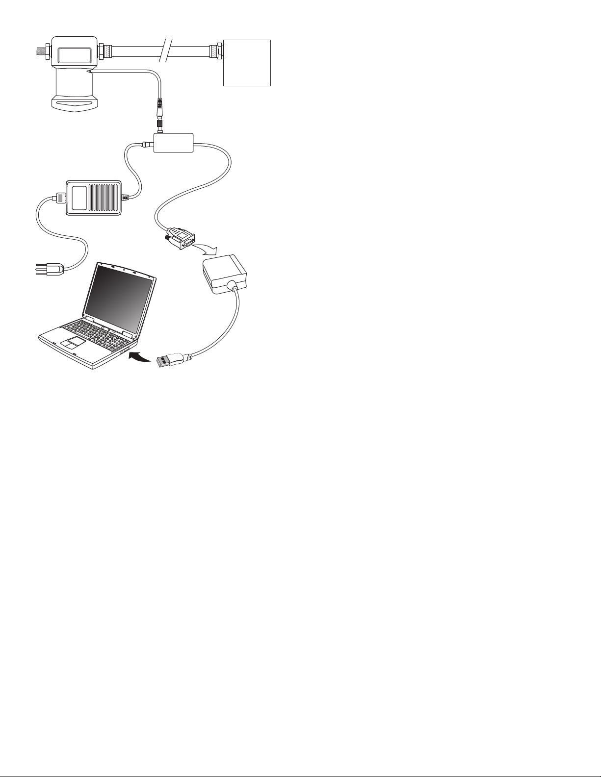
Pressure
Calibrator
Pressure Module
Interface
Line Power
Unit
9-Pin to
USB
Connector
USB
Port
Zero Pressures
In verification and calibration, these instructions refer to a
zero pressure.
In verification, for standard (positive-only reading), vacuum,
or dual-range modules this is equivalent to venting to the
atmosphere. For absolute modules, it is best to apply a
known vacuum pressure as low as possible, but any precisely
known pressure will work.
In calibration, for standard (positive-only reading) and vacuum
modules, the module or pressure calibrator should be vented
to atmosphere. For absolute modules, a known vacuum must
be applied. For dual or compound-range modules, a negative
pressure should be applied that is close to the negative full
span.
As Found Verification
Proceed as follows to collect verification data for the module
before you adjust it. Before you verify the module, exercise it
by applying full scale pressure, then venting to atmosphere.
As found data is saved in a file named “nnnnnnn.fnd,” where
“nnnnnnn” is the serial number of the pressure module. You
can import this file into a database or spreadsheet program.
1. Click on As Found Verification.
2. Apply each requested pressure. Where a zero pressure
is called for, refer to Zero Pressures above.
Wait for the reading to settle (to typically less than 1
count change in 5 seconds) before you go on to each
next step.
3. Click on Done to save the data to a text file.
If Verification Fails by More than 1%
If the pressure module is more than 1% out of tolerance, it
needs full calibration over temperature at a Fluke Service
Center, and possibly repair. Check for tolerance exceeding
1% of full scale by comparing the results of As Found
Verification with the pressure module specifications.
Calibration Adjustment
Using the calibration adjustment procedure, you create new
calibration coefficients and download them into the pressure
module. Before you calibrate the module, exercise it by
applying full scale pressure, then venting to atmosphere.
Proceed as follows to adjust a module:
1. Click on Calibration Adjustment.
2. Apply a zero pressure (refer to Zero Pressures above).
Wait for the reading to settle (to typically less than 1
count change in 5 seconds) before you go on to the next
step.
3. Apply full scale pressure ±5% as requested by the
program. Again, wait for the reading to settle.
4. Test the module by applying any pressure between zero
and full scale. The module is now working with the
updated constants.
5. In cases where the zero error was large, you may have
to perform calibration adjustment twice. To repeat the
calibration adjustment, click on Calibration Adjustment
again, before clicking on Disconnect.
6. Click on Save to Module to download the new constants
and make the changes permanent (until you adjust it
again).
As Left Verification
Proceed as follows to collect verification data for the module
after you have adjusted it. Before you verify the module,
exercise it by applying full scale pressure, then venting to
atmosphere. As left data is saved in a plain text file named
“nnnnnnn.lft,” where “nnnnnnn” is the serial number of the
pressure module. You can import this file into a database or
spreadsheet program.
1. Click on As Left Verification.
2. Apply each requested pressure. Where a zero pressure
is called for, refer to Zero Pressures.
Wait for the reading to settle (to typically less than 1
count change in 5 seconds) before you go on to each
next step.
3. Click on Done to save the data to a text file.
As found data is stored as "nnnnnnn.fnd" where "nnnnnnn" is
the seven or eight-digit serial number. The only difference
between "as found verification" and "as left verification" is that
the file extension is changed to ".lft". All files are stored in the
"data" subdirectory of the working directory.
NOTE
When using the 700PCK with 700P22, 700P23,
or 700P24 Pressure Modules, derate module
specification to 0.1% if electromagnetic field
strength exceeds 2.5 V/m (above 3 V/m not
specified).
 Loading...