

Page 1

Priming the Pump
®
To prime the pump:
1. Before making any connections to the pump remove the
filler cap (item H) and fill the reservoir approximately 2/3
with either distilled water, mineral oil, or hydraulic oil 32
(10 W), and re-install the filler cap until finger tight.
2. Adjust the “Vernier” knob (item D) to the approximate
mid-range.
3. Fully open the pressure bleed knob (item I), turning
counterclockwise until it stops.
4. Hold the pump at a 45 degree angle, with the reservoir
facing up, as shown in the figure “Using the Test Pump.”
5. Pump the handle until fluid appears, then close the
pressure bleed knob.
6. Attach the hose and fill by pumping until fluid begins to
flow.
7. Attach the hose to the Unit Under Test (UUT), make sure
to plug any unused ports on the pump, and continue to
compress the handle until pressure is created.
Note
It may take many compressions of the handle to create pressure
depending on hose length and volume of the UUT.
8. Open the pressure bleed knob to release pressure and
any air trapped in the line until all of the air in the line is
bled off. Repeat if necessary.
9. When testing is complete, disconnect the hose from the
unit under test. If using the Fluke HTH hose, place the
plastic sealing cap back over the exposed end of the
hose to help retain the fluid until the pump is used again.
Retaining the fluid in the hose will greatly reduce the
number of strokes required to re-prime the pump.
Replacement Parts
Rebuild Kit, Fluke PN 2812606
Hydraulic Fluid Reservoir Rebuild Kit, Fluke PN 2844341
Handle Assembly Rebuild Kit, Fluke PN 2844352
LIMITED WARRANTY AND LIMITATION OF LIABILITY
This Fluke product will be free from defects in material and workmanship for
one year from the date of purchase. This warranty does not cover fuses,
disposable batteries, or damage from accident, neglect, misuse, alteration,
contamination, or abnormal conditions of operation or handling. Resellers are
not authorized to extend any other warranty on Fluke’s behalf. To obtain
service during the warranty period, contact your nearest Fluke authorized
service center to obtain return authorization information, then send the product
to that Service Center with a description of the problem.
THIS WARRANTY IS YOUR ONLY REMEDY. NO OTHER WARRANTIES,
SUCH AS FITNESS FOR A PARTICULAR PURPOSE, ARE EXPRESSED OR
IMPLIED. FLUKE IS NOT LIABLE FOR ANY SPECIAL, INDIRECT,
INCIDENTAL OR CONSEQUENTIAL DAMAGES OR LOSSES, ARISING
FROM ANY CAUSE OR THEORY. Since some states or countries do not
allow the exclusion or limitation of an implied warranty or of incidental or
consequential damages, this limitation of liability may not apply to you.
Fluke Corporation
P.O. Box 9090
Everett, WA 98206-9090
U.S.A.
11/99
Fluke Europe B.V.
P.O. Box 1186
5602 BD Eindhoven
The Netherlands
Fluke-700HTP-1
Hydraulic Test Pump
Instruction Sheet
Introduction
The Fluke-700HTP-1 Hydraulic Test Pump (hereafter called
the pump) is a portable source of high pressure. The pump
has the following specifications:
• Maximum pressure: 690 bar (10,000 psi)
• Hydraulic media: distilled water, mineral based hydraulic
oil, or hydraulic oil 32 (10 W).
• Wetted materials: 303 stainless steel, aluminum,
polyurethane, PTFE, nitrile, and nylon
• Weight: 1.29 lb (0.58 kg)
• Dimensions: length 9.5 in (241 mm), width 6.1 in
(155 mm), depth 2.6 in (66 mm)
Box Contents
• Model 700HTP-1 Hydraulic Test Pump with 1/4 in NPT
tee installed
• (2) 1/4 in NPT male to 1/4 in BSP female adapter
• 1/4 in NPT male to 1/4 in NPT male fitting
• Instruction Sheet
Contacting Fluke
To contact Fluke or for service, call one of the following
telephone numbers:
USA: 1-888-44-FLUKE (1-888-443-5853)
Canada: 1-800-36-FLUKE (1-800-363-5853)
Europe: +31 402-675-200
Japan: +81-3-3434-0181
Singapore: +65-738-5655
Anywhere in the world: +1-425-446-5500
Or, visit Fluke's Web site at www.fluke.com
.
PN 2811836
April 2007 Rev.1, 11/08
©2007, 2008 Fluke Corporation. All rights reserved. Printed in U.S.A.
All product names are trademarks of their respective companies.
Page 2
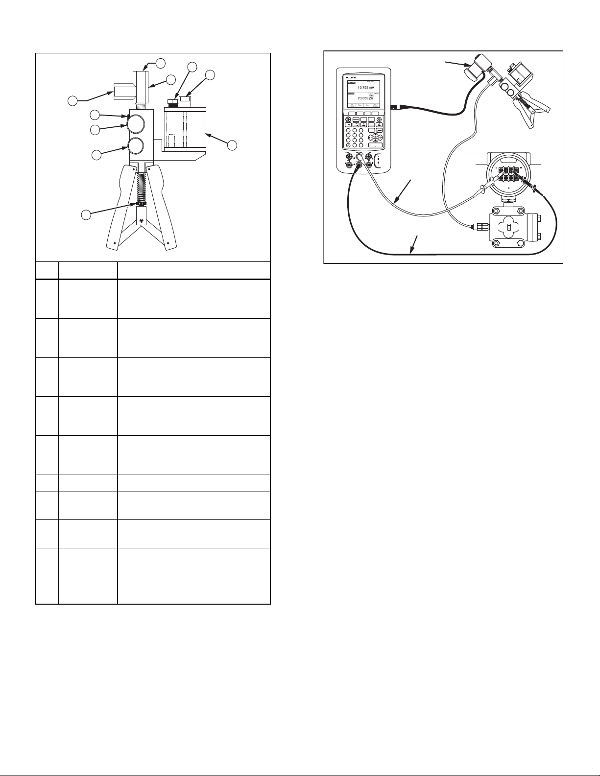
Features
Using the Test Pump
1
8
6
10
Calibrator
DOCUMENTING PROCESS CALIBRATOR
743
Pressure
Module
2
3
4
9
7
No. Item Function
A
B
C
D
E
Master
instrument
port
Test
pressure
port
Pressure
relief valve
port
Fine
adjustment
knob
Hydraulic
fluid
reservoir
Port for Fluke 700 Series Pressure
Module, 1/4 in NPT female
Port for pressure instrument under
test, 1/4 in NPT female
Port for an optional Fluke 700PRV-1
Pressure Relief Valve (plugged)
Allows you to precisely adjust the
applied pressure
Holds 100 cc of hydraulic fluid:
mineral based hydraulic oil, distilled
water, or hydraulic oil 32 (10 W).
F 1/4 NPT tee For master and test ports
Stroke
G
H
I
J
adjust
Reservoir
filler plug
Pressure
bleed knob
Reservoir
nut
Use to adjust handle stroke
Remove this to fill hydraulic fluid
reservoir. Reseal before you pump.
Allows you to release pressure in a
controlled manner
Remove nut to clean reservoir
5
euh01f.eps
Test
Pump
+
UUT
SIGN AL
Ð
TEST
7 8 9
456
123
RTD
SOURCE
30V
MAX
MEAS
SOURCE
V
Hz
0
mA mA
30V
MAX
SETUP
mA
TC
RTD
RANGE
CLEAR
(ZERO)
ENTER
.
V
VV
RTD
CAT
MEAS
300V
TC
MAX
30V
MAX
Red
Black
euh02c.eps
W Warning
To avoid a violent release of pressure, always
depressurize the system slowly using the pressure
bleed knob (item I, left) before you detach any
pressure line from the pump. Do not connect the
pump to an external pressure source.
W Caution
If you are using the pump with a pressure module or
pressure instrument that will be damaged by
pressures of 690 bar (10,000 psi), you can protect the
equipment by installing a properly set relief valve in
the system or an optional Fluke 700PRV-1 Pressure
Relief Valve on the pump.
1. Attach a 700 Series Pressure Module (hereafter called
"pressure module") to the master instrument port A for
all modules except the 700P High Pressure Modules. To
adapt to the 700P29, P30, or P31 Series High Pressure
Modules, install a male 1/4-in NPT Adapter. Use Teflon
tape or other sealing media on NPT thread connections
to eliminate leaks.
2. Remove fill cap and fill reservoir approximately 2/3 full.
3. Connect the pressure module to the calibrator as shown
in the figure.
4. Connect the input of the pressure instrument under test
to the test pressure port (item B).
5. Unscrew the pressure bleed knob (item I) to vent
pressure from the pump.
6. Zero the pressure module. The zeroing procedure
depends on which pressure module and calibrator you
are using.
7. Turn the fine adjustment knob (item D) to mid-range.
8. Tighten the pressure bleed knob finger tight.
9. Set the handle stroke length to maximum.
10. Prime pump as described under “Priming the Pump”.
11. Shorten handle-stroke length to reduce pumping force.
W Caution
Pressure may rise rapidly if the pressurized
volume is small.
12. Compress the handles to apply incrementally higher
pressure.
13. For fine pressure adjustment, use the fine adjustment
knob.
Page 3

Supplement
Title: 700HTP-1 I.S. Supplement Issue: 2
Part Number: 2811836 Issue Date: 2/10
Print Date: April 2007 Page Count: 1
Revision/Date: Rev.1, 11/08
This supplement contains information necessary to
ensure the accuracy of the above Instruction Sheet.
© 2010 Fluke Corporation. x
All rights reserved. Printed in the U.S.A.
Page 4

700HTP-1 Instruction Sheet Manual Supplement
Change #1
Under Introduction, replace the second bullet with the
following:
• Hydraulic media: distilled water, mineral based
hydraulic oil, or up to hydraulic oil 100 (30 W).
Under Box Contents, add the following bullet:
• ¼ in. NPT male to 1/8 in. NPT male fitting
Under Priming the Pump, replace step 1 with the
following:
1. Before making any connections to the pump,
remove the filler cap (item H) and fill the
reservoir approximately 2/3 with either distilled
water, mineral oil, or hydraulic oil and re-install
the filler cap until finger-tight.
Delete step 4, and renumber accordingly.
Under Features, replace No. 5 with the following:
Hydraulic
fluid
E
reservoir
Holds 100 cc of hydraulic fluid:
mineral based hydraulic oil,
distilled water, or hydraulic oil.
2/10 1
 Loading...