

Page 1

PN 2141150
April 2005, Rev.1, 6/05
© 2005 Fluke Corporation, All rights reserved. Printed in UK
All product names are trademarks of their respective companies.
6500
Appliance Tester
Users Manual
Page 2

LIMITED WARRANTY AND LIMITATION OF LIABILITY
Each Fluke product is warranted to be free from defects in material and workmanship under normal use and service. The warranty period is
two years and begins on the date of shipment. Parts, product repairs, and services are warranted for 90 days. This warranty extends only to
the original buyer or end-user customer of a Fluke authorized reseller, and does not apply to fuses, disposable batteries, or to any product
which, in Fluke’s opinion, has been misused, altered, neglected, contaminated, or damaged by accident or abnormal conditions of operation
or handling. Fluke warrants that software will operate substantially in accordance with its functional specifications for 90 days and that it has
been properly recorded on non-defective media. Fluke does not warrant that software will be error free or operate without interruption.
Fluke authorized resellers shall extend this warranty on new and unused products to end-user customers only but have no authority to extend a greater or different warranty on behalf of Fluke. Warranty support is available only if product is purchased through a Fluke authorized
sales outlet or Buyer has paid the applicable international price. Fluke reserves the right to invoice Buyer for importation costs of repair/replacement parts when product purchased in one country is submitted for repair in another country.
Fluke’s warranty obligation is limited, at Fluke’s option, to refund of the purchase price, free of charge repair, or replacement of a defective
product which is returned to a Fluke authorized service center within the warranty period.
To obtain warranty service, contact your nearest Fluke authorized service center to obtain return authorization information, then send the
product to that service center, with a description of the difficulty, postage and insurance prepaid (FOB Destination). Fluke assumes no risk
for damage in transit. Following warranty repair, the product will be returned to Buyer, transportation prepaid (FOB Destination). If Fluke
determines that failure was caused by neglect, misuse, contamination, alteration, accident, or abnormal condition of operation or handling,
including overvoltage failures caused by use outside the product’s specified rating, or normal wear and tear of mechanical components,
Fluke will provide an estimate of repair costs and obtain authorization before commencing the work. Following repair, the product will be
returned to the Buyer transportation prepaid and the Buyer will be billed for the repair and return transportation charges (FOB Shipping
Point).
THIS WARRANTY IS BUYER'S SOLE AND EXCLUSIVE REMEDY AND IS IN LIEU OF ALL OTHER WARRANTIES, EXPRESS OR IMPLIED, INCLUDING BUT NOT LIMITED TO ANY IMPLIED WARRANTY OF MERCHANTABILITY OR FITNESS FOR A PARTICULAR
PURPOSE. FLUKE SHALL NOT BE LIABLE FOR ANY SPECIAL, INDIRECT, INCIDENTAL OR CONSEQUENTIAL DAMAGES OR
LOSSES, INCLUDING LOSS OF DATA, ARISING FROM ANY CAUSE OR THEORY.
Since some countries or states do not allow limitation of the term of an implied warranty, or exclusion or limitation of incidental or consequential damages, the limitations and exclusions of this warranty may not apply to every buyer. If any provision of this Warranty is held invalid or unenforceable by a court or other decision-maker of competent jurisdiction, such holding will not affect the validity or enforceability of
any other provision.
Fluke Corporation, P.O. Box 9090, Everett, WA 98206-9090, U.S.A.
Fluke Europe B.V., P.O. Box 1186, 5602 BD Eindhoven, The Netherlands.
Page 3

Table of Contents
Title Page
Introduction .................................................................................................................... 1
Contacting Fluke ............................................................................................................ 1
Unpacking the Tester ..................................................................................................... 2
Safety Information .......................................................................................................... 2
Operating Features ........................................................................................................ 4
Front panel description .............................................................................................. 4
Understanding the Pushbuttons ................................................................................ 5
Understanding the Beeper Sounds............................................................................ 6
Understanding Displayed Symbols............................................................................ 6
Powering the Tester ....................................................................................................... 7
Understanding the Power-up Screen......................................................................... 7
Setting Up the Tester: Basic Functions .......................................................................... 7
Adjusting the Display Contrast................................................................................... 7
Zeroing the Earth Bond Test...................................................................................... 7
Setting Date and Time............................................................................................... 8
Setting the Site Text .................................................................................................. 8
Setting Up the Tester: Advanced Functions ................................................................... 9
i
Page 4

6500
Users Manual
Changing the Access Code....................................................................................... 9
Selecting Fast or Standard Test Mode...................................................................... 9
Creating/Editing an Auto-Test Sequence .................................................................. 9
Setting Manual Test Limits........................................................................................ 11
Locking and Unlocking Manual Tests........................................................................ 12
Setting the Serial Port Communications Speed ........................................................ 12
Installing - Formatting a Compact Flash Card........................................................... 13
Testing Appliances ........................................................................................................ 14
Aborting a Test.......................................................................................................... 14
Test Modes: Single - Continuous Test ...................................................................... 15
Test Modes: Standard or Fast................................................................................... 15
Using the Auto-Test Mode ........................................................................................ 16
Performing Auto-Tests ......................................................................................... 16
Using the Manual Test Mode .................................................................................... 18
Performing Manual Tests ..................................................................................... 18
Description of the Tests ................................................................................................. 19
Visual Inspection Test ............................................................................................... 19
Bond Test 25A/200 mA (R
Insulation Test (R
)................................................................................................. 20
ISO
).................................................................................... 19
PE
Substitute Leakage Current Test (ISL) ....................................................................... 22
Touch Current Test (ITC)............................................................................................ 23
Load/ Leakage Current (I
) Test.............................................................................. 24
PE
IEC Lead Test ........................................................................................................... 26
PELV Test................................................................................................................. 27
Using the Memory.......................................................................................................... 28
Saving Test Results .................................................................................................. 28
Viewing Test Result Records .................................................................................... 29
Viewing Auto-Test Sequences .................................................................................. 29
ii
Page 5

Contents
Deleting Test Result Records.................................................................................... 30
Clearing the Memory ................................................................................................. 30
Printing - Downloading Data........................................................................................... 31
Connecting the Printer or the PC............................................................................... 31
Printing test results .................................................................................................... 32
Printing Auto-tests ..................................................................................................... 32
Downloading Test Results to a PC ............................................................................ 32
Transferring Results to Compact Flash Card............................................................. 32
Maintaining the Tester.................................................................................................... 33
Cleaning .................................................................................................................... 33
Calibration ................................................................................................................. 33
Accessories ............................................................................................................... 33
Specifications ................................................................................................................. 34
General Specifications............................................................................................... 34
Test Specifications .................................................................................................... 35
Power-on Test ...................................................................................................... 35
Earth Bond Test.................................................................................................... 35
Insulation Test ...................................................................................................... 35
Touch Current Test............................................................................................... 36
Substitute Leakage Current Test .......................................................................... 36
Load/Leakage Test: Load Current ........................................................................ 36
Load/Leakage Test: Load Power .......................................................................... 37
Load/Leakage Test: Leakage Current .................................................................. 37
PELV Test............................................................................................................. 37
Influence Factor Errors ......................................................................................... 37
(continued)
iii
Page 6

Page 7

6500 Appliance Tester
Users Manual
Introduction
The Fluke model 6500 Appliance Tester (hereafter
referred to as ‘the tester’) is designed to carry out the
following tests to ensure the integrity of electrical
equipment / portable appliances:
x L-N Mains Volts and Mains Wiring test.
x Insulation test (500 V dc).
x Earth Bond test 200 mA and 25A with test lead zero
facility.
x Substitute Leakage Current test.
x Touch Current test .
x IEC Lead test.
x Leakage test.
x Appliance Power and Load current test.
x PELV test
Contacting Fluke
To contact Fluke for product information, operating
assistance, service, or to get the location of the nearest
Fluke distributor or Service Centre, call:
x +31-402-678-200 in Europe
Visit Fluke’s web site at: www.fluke.com
Register your Tester at: register.fluke.com
1
Page 8
Fluke 6500
Users Manual
Unpacking the Tester
The tester comes with the items listed in Table 1. If the
tester is damaged or an item is missing, contact the place
of purchase immediately.
Table 1. Shipment Box Contents
6500 Appliance Tester
Crocodile Clip
Test Lead
Touch Current Probe
Hard Case
Users Manual (this manual)
Safety Information
The tester must only be used by a suitably trained and
competent person.
Carefully read the following safety information before
using the tester.
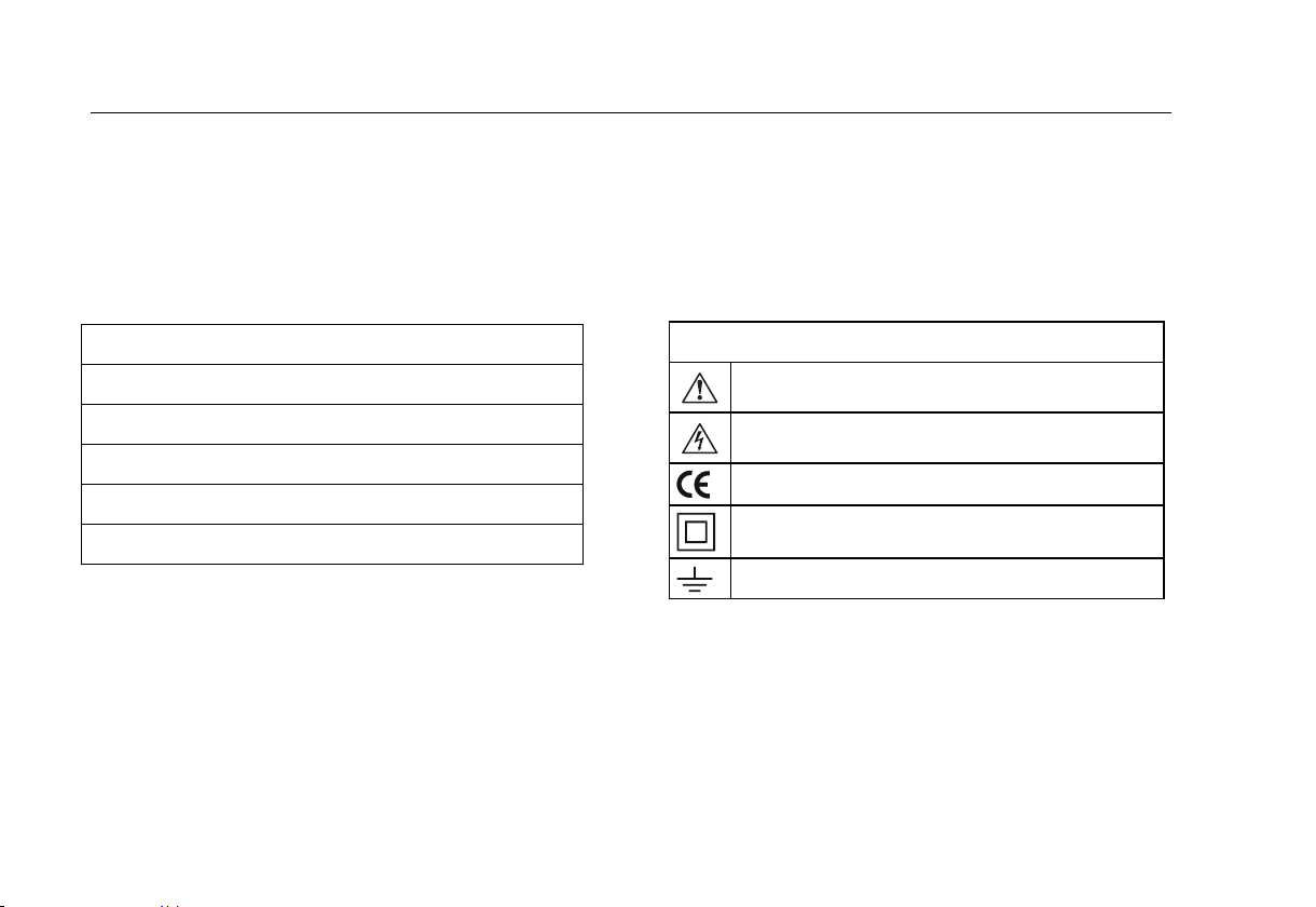
Definitions of symbols used
Caution! Risk of Danger. Refer to Manual
Caution! Risk of Electric Shock
Conforms to Relevant European Standard
Double Insulated (Class II) Equipment
Earth Ground
2
Page 9

Users Manual
Safety Information
Warnings: Read Before Using
To avoid possible electric shock or personal injury,
follow these guidelines:
x If the tester does not power up immediately after
connecting it to the mains outlet disconnect and
verify that the mains outlet is correctly wired.
x Use the tester only as specified in this manual, or the
protection provided by the tester might be impaired.
x The tester shall not be used for measurements in
electrical installations.
x When conducting tests do not touch the appliance as
some tests involve high voltages and high currents.
x Do not use the tester around explosive gas, vapour
or dust, or in wet environments.
x Inspect the tester before using it. Do not use the
tester if abnormal conditions of any sort are noted
(such as a faulty display, broken case, etc.).
x Use only test leads and probes supplied with the
tester, or indicated by Fluke as suitable for the tester.
x Inspect the test leads for damaged insulation or
exposed metal. Check test lead continuity. Replace
damaged leads before using the tester.
x When testing, always be sure to keep your fingers
behind the safety barriers on the test leads.
x Never open the tester’s case because dangerous
voltages are present. There are no user replaceable
parts in the tester.
x Have the tester serviced only by qualified personnel.
x The tester must be properly earthed. Only use a
supply socket that has a protective earth contact. If
there is any doubt as to the effectiveness of the
supply socket earth, do not connect the tester. Do
not use a two-conductor adapter or extension cord;
this will break the protective ground connection.
x The tester has been set for a nominal 230 V ac –
50 Hz operation, it must never be connected to a
higher voltage.
x The tester may only be connected to a correctly
wired mains socket protected for a maximum current
rating of 13 A.
x The mains supply is never to be connected to the IEC
lead test connector or to the appliance test
connector.
x When carrying out Earth Bond tests, regularly zero
the Earth Bond test lead.
x Under certain test conditions the test socket may
have mains potential with a maximum current of
13 A.
x If the tester continuously emits a two tone sound,
you should unplug it immediately as this indicates a
dangerous condition.
3
Page 10
Fluke 6500
Y
X
Users Manual
Operating Features
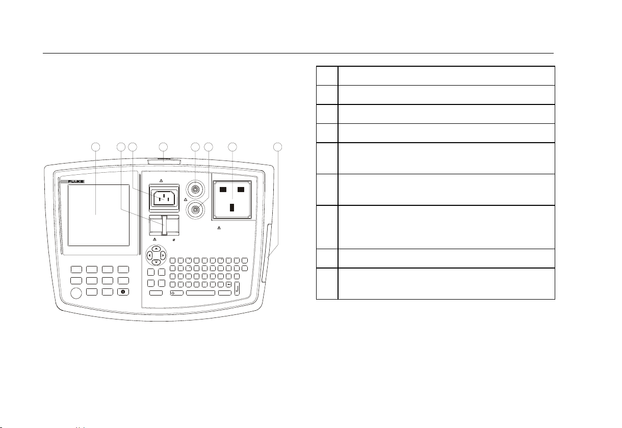
Front panel description
The connectors, controls and indicators of the tester are
shown and listed below.
VISUAL
GOGO
STOPSTOP
1 2
6500
APPLIANCE TESTER
BOND
200 mA
I
SUB
IEC
LEAD
3
4
BOND ZERO
BOND
INSUL-
25 A
ATION
LOAD/
LEAK
AUTO
YES MEM
I
TOUCH
SET
NO
UP
PC/PRINT
Figure 1. Fluke 6500
5
6 7 8
BOND 25A/200mA
IEC
TOUCH PROBE
INSULATION PROBE
CLASS II
PROBE PELV
SWITCH ON APPLIANCE FO R ALL TESTS
.
=
1234567890
£
#
Q
WE R T
ASDFGHJK
Z
CVBNM
CAPS
+
?/
SPACE
230V 50Hz / MAX 13A
:
"
%&
UIO
TEST SOCKET
*
SHIFT
()
L
,
P
No. Description
1 Liquid Crystal Display (LCD).
2 Earth bar to zero the Earth Bond test lead.
3 Socket to connect IEC lead for IEC Lead test .
4 Serial RS-232 Port to connect the Fluke printer,
Fluke bar code scanner, or a computer.
5 Socket to connect test lead and crocodile clip for
Earth Bond test.
6 Socket to connect test probe for Insulation test,
Touch Current test, Substitute Leakage test and
PELV test.
7 Socket to connect the appliance to be tested.
8 Slot to insert a Type I Compact Flash Memory
Card.
4
Page 11
Users Manual
Operating Features
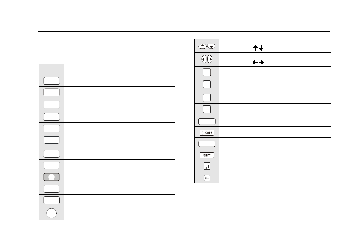
Understanding the Pushbuttons
The table below shows the pushbuttons to control
operation of the tester.
Button Function
INSUL-
ATI ON
BOND
25A
BOND
200mA
VISUAL
TOUCH
LOAD/
LEAK
SUB
GO
AUTO
IEC
LEAD
STOP
Select the Insulation test.
Select the 25 A Earth Bond test.
Select the 200 mA Earth Bond test.
Select the Visual Inspection test.
I
Select the Touch Current test.
Select the combined Load/Earth Leakage
Current test.
I
Select the Substitute Leakage Current test.
Start /Enter selection.
Provide help on the current function.
i
Select the auto-test mode.
Select the IEC Lead test.
Abort the current action and return to idle
screen.
SET
UP
MEM
YES
NO
PC/PRINT
SPACE
Scroll up/down to highlight options in screen
instructions (
).
Move left/right to change options in screen
instructions ( ).
Select the setup menu.
Store test results or viewing auto-test
sequences.
Confirm a proposed action.
Reject a proposed action.
Download/Print test results and auto-tests.
Use capital characters.
Type the space character.
Assign special characters to keys.
Enter typed data.
Backspace.
5
Page 12
Fluke 6500
Users Manual
Understanding the Beeper Sounds
The tester can make several types of beeper sounds.
Sound Meaning
Click A key is pressed.
1 beep A test passed.
2 beeps - A test failed.
- Warning, see display.
- The STOP key is pressed, the
current action is aborted.
Long beep Test will start in continuous
mode.
Continuous two
tone sound
Dangerous condition! Unplug the
unit immediately!
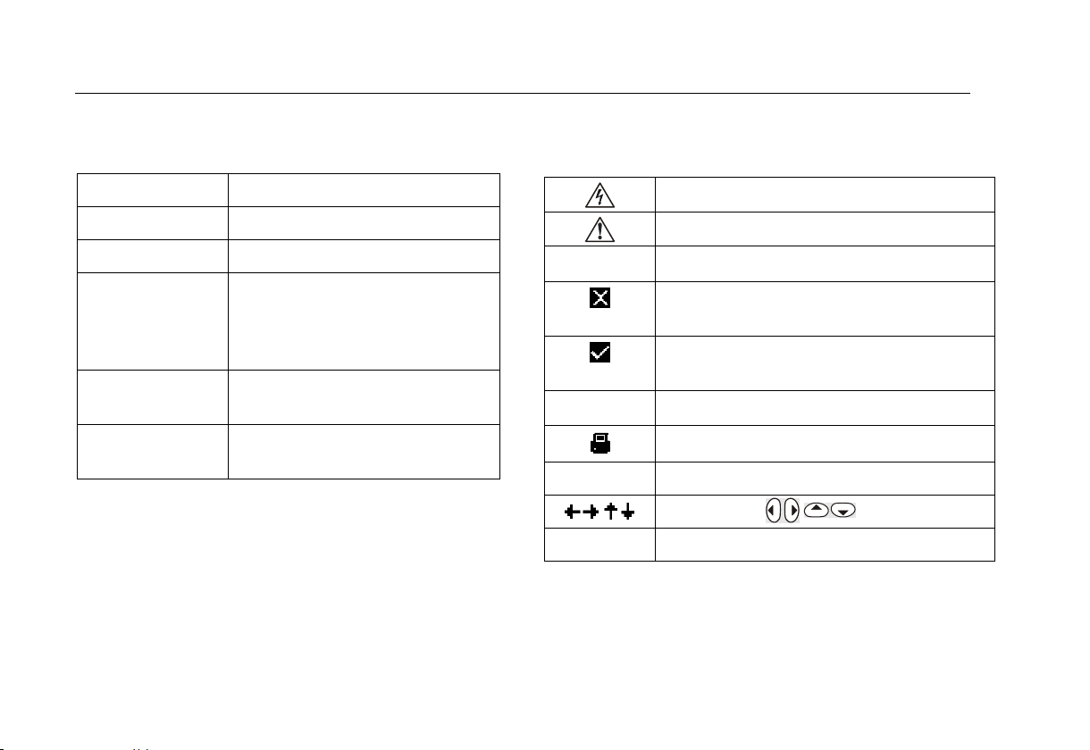
Understanding Displayed Symbols
The following symbols can be displayed:
Caution! Risk of Electric Shock.
Caution! Risk of Danger. Refer to Manual.
Ø
LMT
I II
Lockout on
Bond test lead has been zeroed.
Auto-test failed.
At IEC lead test: L-N/fuse test failed.
Auto-test passed.
At IEC lead test: L-N/fuse test passed.
Applicable limit is exceeded.
The printer/PC is connected.
Class I, Class II.
Use buttons .
Manual tests are locked out.
6
Page 13
Users Manual
Setting Up the Tester: Basic Functions
Powering the Tester
The tester will power up when you connect it to the mains
supply. Disconnect the mains plug to power the tester down.
Warning
Read the safety information on page 2 before
powering the tester.
Understanding the Power-up Screen
On power up the display will perform a self-test. During
this test it shows the Fluke model 6500 and the software
version, for example V1.32.
After performing the self test, if all is well, the tester
shows the idle screen:
23/06/04 10:12
Site: Fluke
VLN 231.2 V
VNE 0.0 V
50.2 Hz
Ø
If there is an error a self explanatory message will
appear. Follow the screen instructions if an error
message is displayed!
m date and time
m most recent entered site name
m live-neutral voltage
m neutral-earth voltage
m line frequency
m bond test has been zeroed
Setting Up the Tester: Basic Functions
This section describes how to set the parameters of the
basic functions.
Adjusting the Display Contrast
To adjust the display contrast, do the following:
1
2 Adjust the contrast.
Zeroing the Earth Bond Test
For correct Earth Bond test results you must zero the
earth bond lead to eliminate its resistance:
x when setting up your new tester. Earth Bond tests are
locked out unless the bond zero icon (
x occasionally, dependent on the condition of the bond
socket and the test lead plug a dirty plug/socket can
result in a significant contact resistance. .
To zero the test lead, do the following:
1
Power the tester up OR
STOP
press STOP to see the idle screen.
SET
Open the setup menu.
UP
Ø) is on.
7
Page 14
Fluke 6500
Users Manual
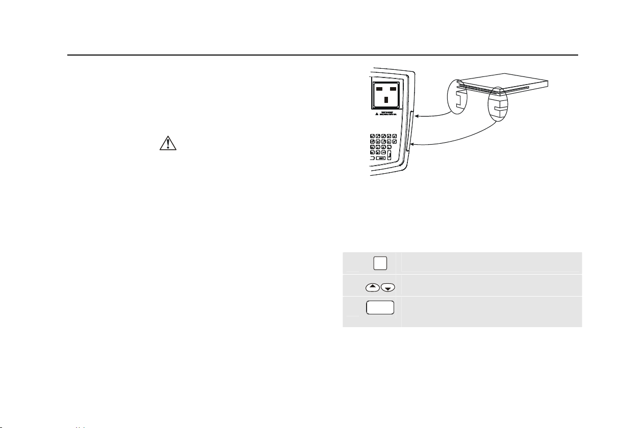
2 Highlight BOND ZERO set.
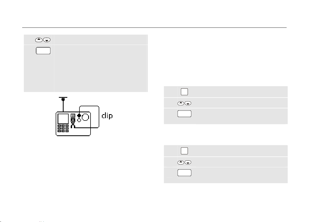
3
Open the setup menu and follow the screen
GO
instructions:
- Attach the crocodile clip to the test lead
and insert the test lead plug into the
BOND 25A/200mA socket, see fig. 2.
- Firmly attach the crocodile clip to the
BOND ZERO Ø bar on the tester.
Figure 2. Bond Zero Connections
When finished the tester shows the bond zero symbol
and the resistance value of the test lead, for example
RPE 0.09 ȍ. It will subtract this value from bond test
results. As it saves this zero value you will not need to
repeat the operation every time you use the tester.
If the display shows the message R
lead resistance is more than 1.99 ȍ and cannot be
zeroed. Earth bond tests will now be locked out.
> 1.99ȍ the
PE
Ø ,
If the Earth Bond test lead has been zeroed, the idle
screen and the earth bond test results screen will show
the zero symbol Ø, for example:
Ø Bond test 25A
Setting Date and Time
The tester has a date and time clock. To set the date and
the time, do the following:
SET
1
Open the set-up menu.
UP
2 Highlight DATE/TIME set.
GO
3
Open the next menu and follow the
screen instructions.
Setting the Site Text
To set the site text, do the following:
SET
1
2 Highlight SITE text set.
3
Open the set-up menu.
UP
GO
Open the next menu and follow the
screen instructions.
8
Page 15

Users Manual
Setting Up the Tester: Advanced Functions
Setting Up the Tester: Advanced
Functions
This section describes how to set the parameters of the
advanced functions.
Changing the Access Code
The factory set access code is 9999. You need the
access code to enter or edit auto-tests, to lock or unlock
manual tests, and to edit the access code. If you forget
your access code contact Fluke.
To change the access code, do the following:
SET
1
2 Highlight ACCESS CODE set.
3
Selecting Fast or Standard Test Mode
In the standard test mode the tester provides help
information during the tests. In the fast mode this
information is bypassed where possible to save test time.
See also ‘Test Modes: Standard or Fast’ on page 15.
Open the set-up menu.
UP
Open the next menu and follow the screen
GO
instructions.
To select the fast or standard mode, do the following:
SET
1
Open the set-up menu.
UP
2 Highlight FAST MODE set.
3
Open the next menu and follow the screen
GO
instructions.
Creating/Editing an Auto-Test Sequence
The tester is provided with factory programmed automatic
test sequences, see page 17. You can create new autotest sequences, and edit tests you created.
To create or edit auto-tests, proceed as follows:
SET
1
2 Highlight AUTO-TEST setup.
3
9 9 9 9
4
5
Open the set-up menu.
UP
Open the User auto-test setup menu.
GO
Enter the access code, for example 9999.
Accept the access code.
GO
9
Page 16
Fluke 6500
123
Users Manual
In the next step you must enter a 3-digit test number:
x Enter a new auto-test number to start creating a user
programmed auto-test from scratch.
x Enter the number of a factory programmed auto-test
to make a copy of it, edit the copy, and store it as a
new user programmed auto-test. See page 17 for the
factory programmed tests.
x Enter the number of an existing user-programmed
auto-test to edit the test.
Continue as follows:
6
7
Enter the test number, for example 123.
Accept the number.
GO
If you entered a factory programmed
number do step 8 and 9 to make a copy.
If you entered a new auto-test number or an
existing user programmed auto-test number
go to step 10.
8
Enter the number to be assigned to the copy
4 5
6
of the factory programmed auto-test, for
example 456.
9
Accept the new auto-test number and enter
GO
the set-up/instruction screen.
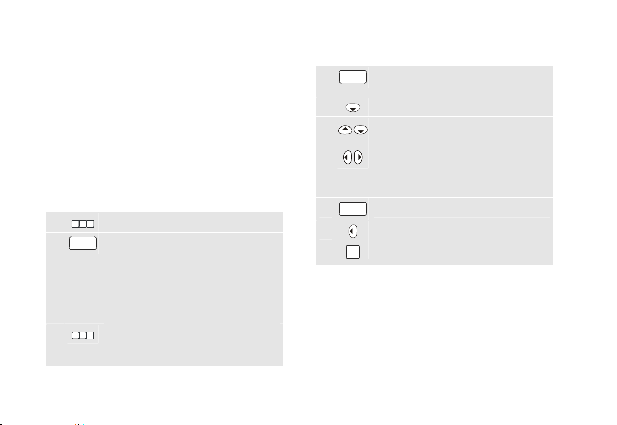
10 Start setting up the test.
11
Use the up/down keys to select the test
parameter(s) to be changed.
Use the left/right arrow key to change the
test parameter
For the test parameters see Table 2.
12
13
When finished exit the set up screen.
GO
To review/edit.
To save the auto-test.
MEM
Notes
Test numbers 137 to 142 and 235 to 240 are
reserved for future factory programmed tests.
User programmed tests are stored in
chronological order and not in numeric order.
To view saved auto-tests see ‘Viewing Auto-Test
Sequences’ on page 29.
10
Page 17
Users Manual
Setting Up the Tester: Advanced Functions
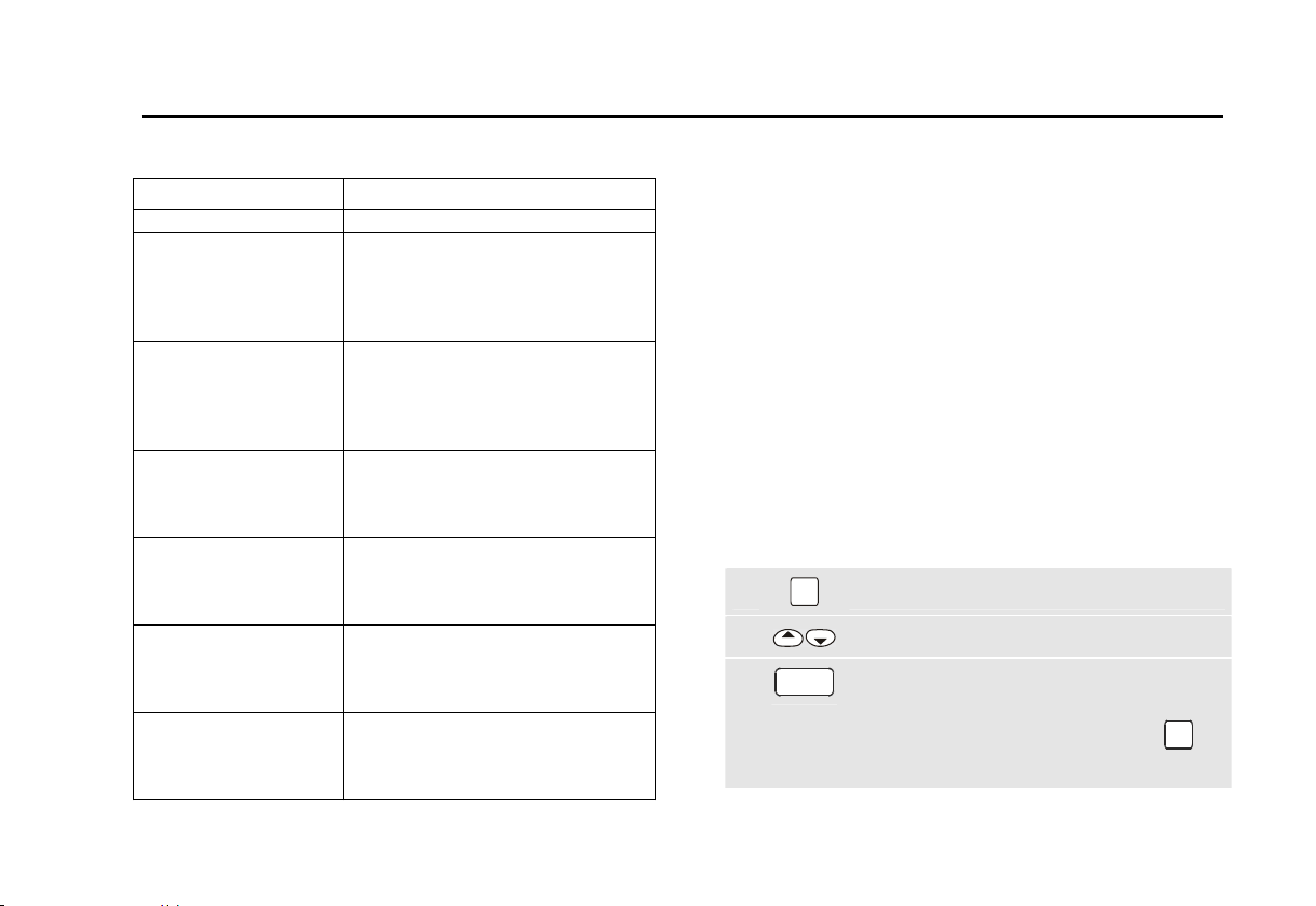
Table 2. Test parameters
Test Parameter
Visual check (Skipped) - SELECTED
Bond
Current
1)
Repeat
Limit
Duration
Insulation
Repeat
Safety Class
Limit
Duration
Substitute Leakage
Limit
Safety Class
Duration
Load/leakage
Limit Load
Limit Leakage
Duration
Touch Current
Repeat
Limit
Duration
IEC Lead
Limit Rpe
Duration
Limit Riso
2)
2)
3)
200mA – 25A
R0 – R1 – R2 - R3
0.1 …19.9
(Skipped) - 5s….60s
R0 – R1 – R2 - R3
I – II
0.1 M…290M
(Skipped) - 5s….60s
0.5mA … 19.5mA
I – II
(Skipped) - 5s….60s
0VA…3200VA
0.5mA …19.5mA
(Skipped) - 5s….60s
R0 – R1 – R2 - R3
0.25mA, 0.5mA – 1.9mA
(Skipped) - 5s….60s
0.1…19.9
(Skipped) - 5s….60s
fixed at 2 M
Notes
1) The repeat test parameters R0, R1, R2, and R3
define how many times a test will be repeated.
When you select for example R1, the test will be
repeated once (two tests).
2) The selected class for the isolation test also
applies to the substitute leakage test.
3) The IEC lead test can only be selected if all
other tests, except for the visual check, are
skipped.
Setting Manual Test Limits
To set the manual test limits you need your access code
(factory default 9999).
Do the following:
SET
1
2 Highlight MANUAL LIMITS
3
Open the set-up menu.
UP
Open the next menu and follow the screen
GO
instructions.
To restore the factory set limits press NO.
For the test parameters see Table 2.
11
Page 18

Fluke 6500
Users Manual
Locking and Unlocking Manual Tests
To unlock/lock manual tests you need your access code
(factory default 9999).
Do the following:
SET
1
2 Highlight MANUAL TEST lock.
3
Open the set-up menu.
UP
Open the next menu and follow the screen
GO
instructions.
Setting the Serial Port Communications Speed
The tester communications speed (baud rate) must
correspond to the communications speed of the
connected printer, bar code scanner, or computer.
To set the communications speed, do the following:
SET
1
2 Highlight COMMS RATE set.
3
The default communications speed setting for the
SP1000 printer and the SP15 scanner is 9600 baud.
Open the set-up menu.
UP
Open the Serial port baud rate menu and
GO
follow the screen instructions.
12
Page 19
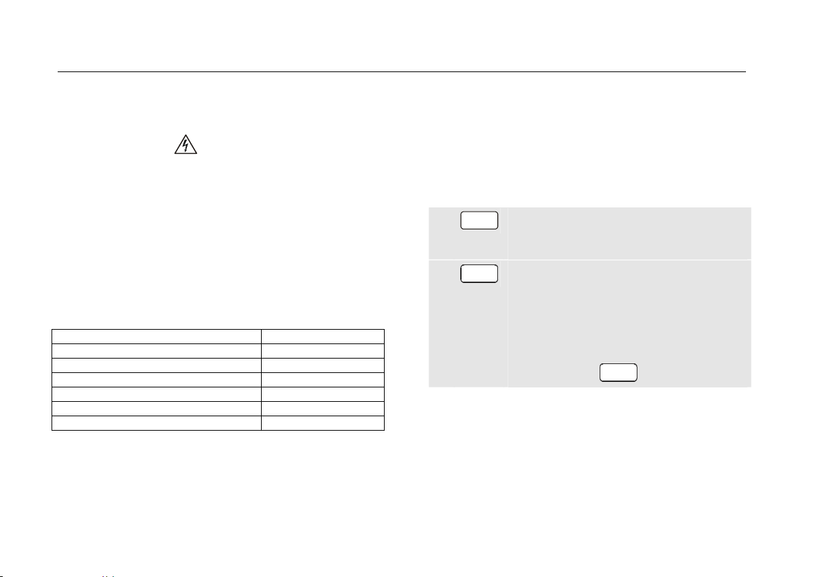
Installing - Formatting a Compact Flash Card
You can copy saved test results and user defined autotests to a Type I Compact Flash Memory Card
(FAT12/FAT16 formatted) for backup purposes.
Caution
x Do not remove the card or do not press
the STOP key during a format or a write
operation. This will damage your card!
x Formatting a card will erase all data on
that card.
x Do not force the CF card into the 6500
card socket. If you encounter resistance,
stop and check that you have plugged in
the card in the correct orientation. If you
use force you may damage the card and
the card reader.
Users Manual
Setting Up the Tester: Advanced Functions
Figure 3. Inserting the CF card
If the card has an invalid file format a screen message will
prompt you to format the card.
To format the card, do the following:
SET
1
Open the set-up menu.
UP
2 Highlight FORMAT a Compact Flash card
To install a card gently insert it into the slot, see figure 3.
To remove the card press the card eject button next to
3
Open the Format menu and follow the
GO
screen instructions.
the slot.
Note
If you are formatting a CF card on a PC, please ensure
you format it to FAT 12 or FAT 16 formats.
13
Page 20

Fluke 6500
Users Manual
Testing Appliances
For the vast majority of testing you can use the auto-test
mode. This is advantageous because you can just follow
the on screen instructions.
The manual test mode is designed for applications where
one particular test must be repeated several times in a
row and to quickly carry out a test.
Warnings
x Before commencing any testing you are strongly
advised to make reference to the Electricity at
Work Regulations 1989 and any relevant
publications from the Health and Safety
Executive.
x The appliance must be switched on for all tests.
x When conducting tests do not touch the
appliance as some tests involve high voltages
and high currents.
x The tests should only be performed by
competent persons who are familiar with the
requirements of the type of tests suitable for
portable appliances.
x It is potentially hazardous for both user and
appliance should the wrong type of tests be
undertaken or if testing is carried out in an
incorrect sequence.
x It is important that you fully understand the
various tests required and how they should be
performed.
x The appliance must have passed the visual
inspection, the earth bond test (Class I), and the
insulation test (in this sequence) prior to any
other test. If any of these fail further testing must
be stopped and any faults must be rectified.
x During the load/leakage test and the touch
current test, the appliance will be energized at
mains voltage. For this purpose, switch on the
appliance. Appliances driven by motors or
equipped with heating units may present a
danger for the person testing (comply with the
appliance instruction manual!). Ensure that the
appliance is in a safe condition to run. Please
secure it prior to the test.
Aborting a Test
Pressing
progress, makes the tester safe and then shows the idle
screen.
STOP
immediately aborts whatever test is in
14
Page 21

Users Manual
Testing Appliances
Test Modes: Single - Continuous Test
You can run manual tests in a single test mode or in a
continuous test mode. A test in the auto-test mode will
always be a single test.
Single Test
To run a single manual test press a test button to select a
GO
test and then press and release
The tester connects the test supply, performs one test,
disconnects the test supply and holds the result on the
display. In the auto-test mode the tester will proceed with
the next test.
Note
To start the Visual Inspection test just press the
VISUAL
key.
Continuous Test
To start a continuous manual test press a test button to
select a test and then press
GO
least 2 seconds. A long beep will indicate the continuous
test has started.
The tester connects the test supply, makes the first test
and displays the first result. Then the tester continues
measuring and displaying results without disconnecting
to start the test.
and hold it down for at
the test supply. The maximum run time is 8 minutes. After
this time the test stops.
To stop a continuous test, press the selected test button
GO
or press
again. The tester disconnects the test
supply and holds the last test result on the display.
Note
The IEC-Lead test cannot be run in the
continuous test mode.
Test Modes: Standard or Fast
In the standard test mode the tester displays instructions
on how to perform a test. The factory-set mode is the
standard mode.
In the fast test mode screen instructions will be bypassed
where possible. During auto-tests in the fast mode the
Visual test is assigned a pass and the test screen is not
shown.
To select the fast mode or standard mode see ‘Selecting
Fast or Standard Test Mode’ on page 9.
15
Page 22

Fluke 6500
Users Manual
Using the Auto-Test Mode
The tester provides a number of factory programmed
auto-tests, see Table 3 (Class I appliances) and Table 4
(Class II appliances). An auto-test consists of a number of
single tests that will be carried out in the programmed
order. The test limits are pre-set, and the test result will
give a pass/fail indication.
See page 9 on how to create new auto-tests.
Auto-tests are locked out unless the Earth Bond test lead
resistance has been zeroed out, see page 7.
When any test fails during an auto-test, further tests can
not be carried out .
Performing Auto-Tests
You can run an auto-test in the standard mode or in the
fast mode. See ‘Test Modes: Standard or Fast’ on page
15 and ‘Selecting Fast or Standard Test Mode’ on page 9
for more information.
To start an auto-test, do the following:
AUTO
1
Select the auto-test mode and follow the
screen instructions.
The chapter ‘Description of the Tests’ on page 19
provides detailed information on the individual tests.
When the auto-test is finished a pass ( ) or a fail (
indication is displayed. Now you can review the results
before saving them, and save the results.
)
16
Page 23

Users Manual
Testing Appliances
Table 3. Factory Programmed Auto-Tests for Class I Appliances
Tests 131 132 133 134 135 136
Visual Inspection Yes Yes Yes Yes Yes Yes
Earth Bond 25A () 0.10 0.10 No No 0.10 No
Earth Bond 200mA No No 0.10 0.10 No 0.10
Insulation (M) 1.00 1.00 1.00 1.00 1.00 1.00
Touch Current (mA) No No No No No No
Substitute Leakage (mA) No No No No No No
Load/Leakage (VA/mA) 3000/3.5 3000/0.75 3000/3.5 3000/0.75 No No
Table 4. Factory Programmed Auto-Tests for Class II Appliances
Tests 231 232 233 234
Visual Inspection Yes Yes Yes Yes
Earth Bond 25A () No No No No
Earth Bond 200mA No No No No
Insulation (M) 2.00 2.00 2.00 2.00
Touch Current (mA) 0.25 0.25 No No
Substitute Leakage (mA) No No No No
Load/Leakage (VA/mA) 3000/0.25 No No 3000/0.25
Note: Test numbers 137 to 142 and 235 to 240 are reserved for future factory programmed tests.
17
Page 24
Fluke 6500
Users Manual
Using the Manual Test Mode
To lock/unlock manual tests see page 12 .
Performing Manual Tests
You can run manual tests in the standard mode or in the
fast mode. See ‘Test Modes: Standard or Fast’ on page
Warning
NEVER carry out the TOUCH CURRENT and
LOAD/LEAKAGE test unless you have first
15 and ‘Selecting Fast or Standard Test Mode’ on page 9
for more information.
To perform a manual test do the following:
carried out a thorough visual inspection,
followed by a test of the earthing (Class I
1 Select the required test key.
appliances), and then a test of the insulation.
You must verify that these tests are passed
before engaging this test.
GO
2
Table 5 shows the factory-set manual test limits.
Table 5. Factory-set manual test limits
Earth Bond 0.10
Insulation class I/class II 1 M / 2 M
Substitute Leakage class I/class II 3.5 mA / 0.5 mA
Touch Current 0.25 mA
Load 3200 VA
Leakage current 0.75 mA
IEC lead bond/insulation 0.10 / 2 M
To change the test limits refer to page 11.
For more information on the individual test refer to
‘Description of the Tests’ on page 19.
After performing a test you can save the result, see
‘Saving Test Results’ on page 28.
Earth Bond tests are locked out if you did not zero the
earth bond test lead resistance, see page 7.
Follow the screen instructions.
Press and release for a short single test.
Press for longer than 2 seconds for a
continuous test (not applicable for a visual
inspection and IEC lead test).
To stop a continuous test, press the selected
test key or press
GO
again.
18
Page 25

Users Manual
Description of the Tests
Description of the Tests
Visual Inspection Test
Visually inspect the appliance before you start electrical
testing.
Check the appliance for the following:
x condition of the appliance cables, i.e. no cuts, cracks
or any physical damage to the outer insulation layer.
x condition of the plug, cable securely attached, no signs
of overheating and that the correct value of fuse is
fitted.
x any signs of damage, and that any mains or control
switches will physically switch on and off.
x any sockets for signs of overheating or physical
damage.
Bond Test 25A/200 mA (RPE)
The test checks the resistance between the earth pin of
the appliance cable plug and the exposed metalwork on
the appliance. The test applies to Class I appliances.
Remarks:
x To enable the bond test and to obtain correct bond test
results you must have zeroed the test lead, see page 7.
x You should use the lower current 200 mA for certain
appliances. Please refer to appliance test standards
and guidance material.
x Connect the appliance and the earth bond test lead as
indicated on the display. Clip the crocodile clip to an
exposed conductive part on the appliance that requires
testing, see fig. 4.
Do not use the probe for the 25 A bond test. The probe
is only rated for 10 A!
x During the measurement flex the flexible cord along its
length to help find any broken conductors or poor
quality joints.
x Continuous 25 A bond test will periodically drop back
to 200 mA test to prevent the tester from being
overheated.
19
Page 26

Fluke 6500
Users Manual
Figure 4. Bond Test Connections
The display can show the following specific information:
LMT
>0.1ȍ+LEAD
R
may have exceeded the
PE
recommended limit, possibly because
of the length of the lead.
> 19.99
Ø
RPE overrange.
Bond test lead has been zeroed.
Insulation Test (R
ISO
)
Warning
x The test voltage is 500V dc. Do not touch
the appliance during the insulation test!
If the test fails any metal parts of the
appliance could become live!
x Always make sure that the test has
completed before disconnecting the
appliance leads to ensure that all
capacitances have discharged.
Caution
Do not perform the Insulation test on
appliances that failed the bond test or the
visual inspection test.
The test checks the resistance of the insulation between
x the earth pin of the appliance cable plug (Class I)
or
x the test probe to be applied to the appliance (Class II)
and the Live and Neutral pins of the appliance (pins are
connected together within the tester for this test).
The insulation test will be inhibited if the tester detects a
terminal voltage >30 Vrms prior to initiation of the test.
20
Page 27

Note
The insulation test may be not suitable for some
types of appliances. For these appliances an
alternative test may be conducted such as a
touch current, leakage current, or substitute
leakage current test. It is essential to refer to
standards and/or reference material for the safe
applicability of these alternative tests.
Remarks:
x Connect the appliance and the test probe as indicated
on the display, see fig. 5 and fig. 6.
x For Class I appliances no probe is required.
x For Class II appliances apply the test probe to any
exposed metalwork on the appliance. Do the test for all
exposed metal parts on the appliance.
Users Manual
Description of the Tests
Figure 6. Insulation Test Connections Class II
The display can show the following specific information:
LMT <1.0Mȍ
The test result is below the
recommended class I limit.
LMT <2.0Mȍ
The test result is below the
recommended class II limit.
> 299 Mȍ
R
overrange.
ISO
Figure 5. Insulation Test Connections Class I
21
Page 28

Fluke 6500
Users Manual
Substitute Leakage Current Test (I
SL
)
The test measures the leakage current between
x the earth pin of the appliance cable plug (Class I)
or
x the test probe attached to the appliance under test
(Class II)
and the Live and Neutral pins of the appliance (pins are
connected together within the tester for this test).
It is essential to refer to standards and/or guidance
material for the safe applicability of this test.
Remarks:
x Connect the appliance and the test probe as indicated
on the display, see fig. 7 and fig. 8.
x For Class I appliances no test probe is required.
x For Class II appliances apply the test probe to any
exposed metalwork on the appliance. Do the test for all
exposed metal parts on the appliance.
Figure 7. Substitute Leakage Test Connections Cl. I
Figure 8. Substitute Leakage Test Connections Cl. II
The display can show the following specific information:
LMT
> 3.5 mA
The acceptable test limit may have been
exceeded. Refer to standards and/or
guidance material.
> 19.99 mA
I
overrange.
SL
22
Page 29

Users Manual
Description of the Tests
Touch Current Test (I
TC
)
Warning
NEVER carry out this test unless you have first
carried out a thorough visual inspection, followed
by a test of the earthing (Class I appliances), and
then a test of the insulation. You must verify that
these tests have passed before engaging this test.
Caution
Live test! The appliance will be energized at
mains voltage. For this purpose, switch on the
appliance. Appliances driven by motors or
equipped with heating units may present a
danger for the person testing (comply with the
appliance instruction manual!). Ensure that the
appliance is in a safe condition to run. Please
secure it prior to the test.
The Touch Current test consists of:
x a fuse and L-N loop pre-test
x a leakage current measurement with approx. 2 k
resistance connected between earth and exposed
conductive parts on the appliance via the test probe.
The measurement is performed by the direct method.
Connect the appliance and the test probe as indicated on
the display (see fig. 9) and apply the test probe to:
x any exposed conductive part on Class II appliances
x any exposed conductive parts that are not connected
to earth on Class I appliances.
Figure 9. Touch Current Test Connections
The display can show the following specific information:
Live test going on!
LMT
> 1.99 mA
The acceptable test limit may have been
exceeded. Refer to standards and/or
guidance material.
Touch current overrange.
23
Page 30

Fluke 6500
Users Manual
Fuse/L-N Pre-test
The pre-test verifies the fuse and lead continuity by
applying a low voltage signal across the appliance phase
and neutral pins.
If the pre-test fails the display will show a self-explanatory
message.
A fail may indicate that the fuse is blown or that there is
an open circuit in the L-N conductors. In this case press
MEM
the
key to store the fail result.
The test could also fail because you forgot to switch the
appliance on. In this case switch the appliance on and
repeat the test.
Very low power appliances, or appliances with
electronically controlled on/off switches or with an
inductance may fail this test. To enable you to test these
appliances you can assign a pass to the Fuse/L-N loop
GO
Pre-test by pressing
to continue with the test.
Note
Accidental measurement of a defective unit may
trip a RCCB (residual current circuit breaker).
Load/ Leakage Current (IPE) Test
Warning
NEVER carry out this test unless you have
first carried out a thorough visual inspection,
followed by a test of the earthing (Class I
appliances), and then a test of the insulation.
You must verify that these tests are passed
before engaging this test.
Caution
Live test! The appliance will be energized at
mains voltage. For this purpose, switch on
the appliance. Appliances driven by motors
or equipped with heating units may present a
danger for the person testing (comply with
the appliance instruction manual!). Ensure
that the appliance is in a safe condition to
run. Please secure it prior to the test.
The Load/PE Leakage test consists of:
x a fuse and L-N loop pre-test.
x measurements of the appliance power consumption
and load current at full mains voltage.
x measurement of the earth leakage current (differential
measurement) at full mains voltage.
The measurements will be done in one test sequence.
24
Page 31

Users Manual
Description of the Tests
Connect the appliance as indicated on the display (see
also figure 10) .
Figure 10. Load / Leakage Test Connections
The display can show the following specific information:
Live test going on.
ILN 1.2 A
250 VA
P
LN
I
0.3 mA
PE
LMT
Load current.
Reactive power.
Leakage current.
The acceptable test limit may
have been exceeded. Refer to
standards and/or guidance
material.
ILN > 13 A
> 3.2kVA
P
LN
I
>19.99 mA
PE
Load current overrange.
Power overrange.
Leakage current overrange
Fuse/L-N Pre-test
The pre-test verifies the fuse and lead continuity by
applying a low voltage signal across the appliance phase
and neutral pins.
If the pre-test fails the display will show a self-explanatory
message.
A fail may indicate that the fuse is blown or that there is
an open circuit in the L-N conductors. In this case press
MEM
to store the fail result.
The test could also fail because you forgot to switch the
appliance on. In this case switch the appliance on and
repeat the test.
Very low power appliances, or appliances with
electronically controlled on/off switches or with an
inductance may fail this test. To enable you to test these
appliances you can assign a pass to the Fuse/L-N loop
Pre-test by pressing
GO
to continue with the test.
Note
Accidental measurement of a defective unit may
trip a RCCB (residual current circuit breaker).
25
Page 32

Fluke 6500
Users Manual
IEC Lead Test
The IEC lead test tests the IEC lead for:
x Earth bond resistance and insulation.
x Live-neutral lead/fuse continuity and polarity.
If there is a swapped polarity condition and a continuity
failure in the same test, a failed polarity message will be
displayed.
The IEC lead test runs only in single test mode.
Connect the IEC lead as indicated on the display (see
also figure 11).
Figure 11. IEC Lead Test Connection
The display can show the following specific information:
R
PE
0.13 ȍ
Protective earth conductor
resistance.
R
55.6 Mȍ
ISO
Fuse
LMT
Insulation resistance.
The fuse/continuity is ok
One of the test limits has
been exceeded.
Fuse
Polarity
RPE> 19.99 ȍ
R
> 299 Mȍ
ISO
LMT >0.1ȍ+LEAD
Fuse/continuity not ok
L-N are swapped
Result overrange.
has exceeded the
R
PE
recommended limit,
possibly because of the
length of the lead.
LMT <2.0Mȍ CII
The test result is below the
recommended class II limit.
26
Page 33

Users Manual
Description of the Tests
PELV Test
The PELV (Protective Extra Low Voltage) test measures
the voltage on the PROBE PELV input when the idle
screen is being displayed.
To perform the PELV test, do the following:
1
2
3 Apply the test probe to the test point.
4
Revert to the idle screen if it is not already
STOP
being displayed.
Connect the test probe to the tester PROBE
PELV terminal and connect the appliance to
a mains supply socket.
MEM
Store the test result, if required.
The display can show the following specific information:
PELV 30.0 V
PELV FAIL result, the
threshold (25V) is exceeded.
PELV > 39.9 V
230 V
50 Hz
PELV overrange.
If the PELV threshold is not
exceeded the display shows
the mains voltage and
frequency (PASS result)
Tip:
To store a PELV FAIL result press
To store a PELV PASS result press
MEM
MEM
GO
and
.
and select menu
item “SAVE PELV pass result“.
27
Page 34

Fluke 6500
Users Manual
Using the Memory
The tester has a non-volatile memory to save test results
and auto-test sequences.
Saved test results or auto-tests will not automatically be
saved on the compact flash card. The compact flash card
is intended to be used as a backup for the non-volatile
memory. Refer to page 32 for information on how to
download the memory contents to compact flash card.
Beside saving test results and auto-tests you can also
view saved results, delete individual result records, clear
the entire memory and review auto-tests.
Saving Test Results
In the auto-test mode and in the manual single test mode
you can save test results when a test has finished.
In the manual continuous test mode you can save the
displayed test result. The display reverts to the testing
screen after the results have been saved.
Warning
In continuous test mode the test continues
whilst you are saving the result!
Proceed as follows to save the results:
MEM
1
Open the Save result screen and enter
appliance information.
2
Save test results and information.
GO
The Save result screen will present you four fields that
you can enter data into. The data can be inserted via the
keyboard or the Fluke barcode scanner.
Appliance ID
Location
Description
Note
m Mandatory field
m Optional field
m Optional filed
m Optional field
Appliance ID
MEM
On pressing
the Appliance ID field will :
x automatically be incremented by 1 from the last stored
value if you are using numeric only appliance ID
references.
x show the last appliance ID If you are using
alphanumeric ID references.
28
Page 35

Users Manual
Using the Memory
Location
MEM
On pressing
the display shows the last stored
location as long as the tester has not been powered
down.
Note
You can use the 4-digit Fluke coding system for
the description, location, and notes field. This
speeds up data entry. Please refer to the Fluke
Power PAT Plus software.
Remarks:
x After saving the results the display shows the record
number in the top right.
x If the display shows the warning
you must save the data on PC or memory card
full
The store is
and clear the store (see page 30).
x If you press
MEM
when the idle screen is displayed a
PELV test pass result can be saved. See also ‘PELV
Test’ on page 27.
Viewing Test Result Records
You can select the result records you want to view by
record number, by date, by site, and by keyword search.
To view result records proceed as follows:
MEM
1
From the idle screen open the memory
menu and follow the screen instructions.
To see the idle screen press the STOP key.
2 Highlight VIEW RESULT records.
3
Enter the view function and follow the screen
GO
instructions.
Viewing Auto-Test Sequences
You can view factory set and user defined auto-test
sequences by simply scrolling through the store.
Proceed as follows:
MEM
1
2 Highlight VIEW AUTO-TESTS.
3
From the idle screen open the memory
menu and follow the screen instructions.
To see the idle screen press the STOP key.
Enter the view function and follow the screen
GO
instructions.
29
Page 36

Fluke 6500
Users Manual
Deleting Test Result Records
You can select the result records you want to delete by
record number, by date, by site, and by keyword search.
To delete test result records proceed as follows:
MEM
1
2 Highlight DELETE a record.
3
Result records are not renumbered when a record in the
middle of the store is deleted.
Deleting records does not free memory space! To free
memory space see ‘Clearing the Memory’ on page 30.
From the idle screen open the memory
menu.
To see the idle screen press the STOP key.
Enter the delete function and follow the
GO
screen instructions.
Clearing the Memory
To free memory you must clear the store. This will delete
all result records. Automatic test procedures will not be
cleared.
Caution
Before clearing the store you need to be sure
that the contents has been downloaded to
PC and/or backed-up on Compact Flash
Memory card.
To clear the memory proceed as follows:
MEM
1
2 Highlight CLEAR.
3
From the idle screen open the memory
menu.
To see the idle screen press the STOP key.
Enter the Clear menu and follow the screen
GO
instructions.
30
Page 37

Users Manual
Printing - Downloading Data
Printing - Downloading Data
The PRINT/DOWNLOAD functions enable you to :
x print some or all test results.
x print all auto-tests.
x download some or all test results to a PC for
processing with Fluke Power PAT Plus software.
x download some or all test results to a Compact Flash
memory card.
Only results or auto-tests that have been stored can be
printed or downloaded.
You can download results in one of the following formats:
x .flk for Fluke PowerPAT Plus software.
x .csv (comma separated values), for example for
Windows Excel.
x .prn SP1000 printer format (to compact flash card
only).
Connecting the Printer or the PC
To establish a correct communication do the following:
1
Connect the SP1000 printer to the RS232 port using
the cable supplied with the printer. In idle mode and
in the print function the display shows the printer
icon when the printer is connected and is turned
on.
2
Connect the PC to the RS232 port using the cable
that is supplied with the Fluke Power PAT Plus
software. Refer to this software for more specific
information.
3
Ensure that the baud rate of the tester matches the
printer baud rate (9600) or the PC com port baud
rate. To set the tester baud rate see page 10.
31
Page 38

Fluke 6500
Users Manual
Printing test results
To print one test result record or a range of test result
records do the following:
1
PC/PRINT
2
Open the print/download menu.
Highlight Print results (not possible if no
results are available).
3
Open the print results menu and follow the
GO
screen instructions.
Printing Auto-tests
To print all user programmed auto-tests do the following:
1
PC/PRINT
2 Highlight Auto-Tests printout.
3
Open the print/download menu.
Start printing.
GO
Downloading Test Results to a PC
To download a range of test results to a PC using the
Fluke Power PAT Plus software do the following:
PC/PRINT
1
2
Open the print/download menu.
Highlight Download to PC (not possible if
no results are available).
3
Open the Download to PC menu and follow
GO
the screen instructions.
Transferring Results to Compact Flash Card
To transfer a range of test results to a compact flash card
do the following:
PC/PRINT
1
2
3
The download format to be selected depends on the
software you use to process the results, for example print
format, Fluke Power PAT Plus format or CSV format (for
Excel).
Open the print/download menu.
Highlight Transfer data to CF card (not
possible if no results are available).
Open the Transfer menu and follow the
GO
screen instructions.
32
Page 39

Users Manual
Maintaining the Tester
Maintaining the Tester
Cleaning
Periodically wipe the case with a damp cloth and mild
detergent. Do not use abrasives or solvents.
Dirt or moisture on the earth bond test lead plug can
result in a contact resistance that affects the readings.
Therefore periodically zero the earth bond test (see page
7).
Calibration
To ensure the accuracy of the tester is maintained at high
level it is recommended that the tester is calibrated at
least once every 12 months. Calibration must be carried
out by qualified personnel. Contact your local Fluke
representative for calibration ( see ‘Contacting Fluke’ on
page 1).
Accessories
Table 6 and Table 7 list the part numbers of the
accessories.
To obtain the accessories contact your local Fluke
representative, see ‘Contacting Fluke’ on page 1.
Table 6. Standard Accessories
Item Part Number
Crocodile Clip 532269474055
Test Lead 532269474056
Touch Current Probe 1276841
Users Manual (this manual)
1)
Can be downloaded from your regional Fluke website,
start at www.fluke.com .
Table 7. Optional Accessories
Item Part
SPSCAN15 Barcode Scanner 1995050
SP1000 Mini Printer 1597281
EXTL100 Extension Lead Test Adapter 2414348
TA700 Appliance Adapter for 110V Tools 2389678
Fluke PowerPAT Plus Appliance Testing
Software
1)
Number
2143155
33
Page 40

Fluke 6500
Users Manual
Specifications
General Specifications
Size..................... 200 mm (L) x 275 mm (W) x 100 mm (H)
Weight....................................................................... 3.0 kg
Power Supply................ 230 V + 10 % - 15 %, 50 Hz ± 2 %
Power Consumption (Tester) ................. 13 W typical (idle)
........................................60 W max. during 25A Bond Test
Operating temperature...................................... 0 to +40 qC
Storage temperature...................................... -10 to +60 qC
Relative Humidity
.............................................non condensing < +10 qC
...............................................95% from +10 to +30 qC
...............................................75% from +30 to +40 qC
Operating Altitude ....................................... 0 up to 2000 m
Sealing..................... IP-40 (enclosure), IP-20 (connectors)
EMC............................complies with EN61326-1, criteria B
EMI Immunity.............................................................3 V/m
Safety........................Complies with EN61010-1 2
DIN VDE0404-1 and DIN VDE0404-2
CAT II, 300 V, pol 2
Printer – PC RS232 Interface
Baud rate ....................................factory default 9600,
selectable 1200, 2400, 9600, 19200, 38400
Data bits .................................................................... 8
Stop bits..................................................................... 1
Parity ....................................................................... no
nd
edition
34
Page 41

Users Manual
Specifications
Test Specifications
The accuracy specification for the display range is
defined as ± (%reading + digit counts) at 23 °C ± 5 °C,
≤ 75 % RH. Between 0 °C and 18 °C and between 28 °C
and 40 °C, accuracy specifications may degrade by 0.1 x
(accuracy specification) per °C.
The measurement range meets the service operating
errors specified in EN61557-1: 1997, EN61557-2: 1997 ,
EN61557-4: 1997, DIN VDE0404-2.
Power-on Test
The test indicates reversed L-N, missing PE, and
measures the mains voltage and frequency.
Operational Error Measurement Range ...... 195 V to 253 V
Display Range............................................... 90 V to 264 V
Accuracy at 50 Hz ..................................± ( 2% + 3 counts)
Resolution .................................................................. 0.1 V
Input Impedance........................................> 1 M // 2.2 nF
Maximum Input Mains Voltage .................................. 300 V
Earth Bond Test
Operational Error Measurement Range ......... 0.2 to 1.99
Operational Error.......................................................10.0%
Accuracy (after Bond Test zeroing) ........± ( 5% + 4 counts)
Display Range ................................................. 0…19.99
Resolution ................................................................0.01
Test Current ...................200 mA ac -0% +40% into 1.99
25 A ac ± 20 % into 25 m at 230 V
Open Circuit Voltage ............................ > 4 V ac, < 24 V ac
Bond Test Zeroing.......................can subtract up to 1.99
Used Current for Bond Test Zeroing ............................ 10A
Insulation Test
Operational Error Measurement range............. 0.1 to 5 M
Operational Error.........................................................9.0%
Accuracy ...................± (5% + 2 counts) from 0.1 to 50 M
± (10% + 2 counts) from 50 to 299 M
Display Range ................................................. 0 to 299 M
35
Page 42

Fluke 6500
Users Manual
Resolution....................................0.01 M (0 to 19.99 M)
0.1 M (20 to 199.9 M)
1 M (200 to 299 M)
Test Voltage..............500 V dc –0 % +25 % at 500 k load
Test Current........... >1 mA at 500 k load, < 15 mA at 0
Auto discharge time ....................................< 0.5 s for 1 μF
Max. Capacitive Load ...................... operational up to 1 μF
Touch Current Test
Operational error Measurement Range .. 0.1 to 1.99 mA ac
Operational error......................................................... 6.0%
Accuracy ................................................. ± (4% + 2 counts)
Display Range ........................................... 0 to 1.99 mA ac
Resolution.............................................................. 0.01 mA
Internal Resistance (via probe) ....................................2 k
Measuring method .....................................................Probe
The appliance under test is energized at mains potential.
Substitute Leakage Current Test
Operational Error Measurement Range ...0.25 to 19.00 mA
Operational Error .........................................................10%
Accuracy ................................................. ± (5% + 5 counts)
Display Range ......................................... 0 to 19.99 mA ac
Resolution..............................................................0.01 mA
Test Voltage................................................. 35 V ac ± 20%
Load/Leakage Test: Load Current
Display Range ......................................................0 to 13 A
Accuracy ................................................. ± (4% + 2 counts)
Resolution...................................................................0.1 A
The appliance under test is energized at mains potential.
36
Page 43

Users Manual
Specifications
Load/Leakage Test: Load Power
Display Range.................................................. 0 to 999 VA
1.0 kVA to 3.2 kVA
Accuracy .................................................± (5% + 3 counts)
Resolution .............................................1 VA (0 to 999 VA
0.1 kVA (1.0 kVA to 3.2 kVA)
The appliance under test is energized at mains potential.
Load/Leakage Test: Leakage Current
Operational Error Measurement Range ...0.25 to 19.00 mA
Operational error .......................................................12.0%
Accuracy .................................................± (4% + 5 counts)
Display Range..........................................0.25 to 19.99 mA
Resolution ............................................................. 0.01 mA
The appliance under test is energized at mains potential.
PELV Test
Display Range ........................................... 10.0 V to 39.9 V
Resolution .................................................................. 0.1 V
Accuracy at 50 Hz ..................................± ( 2% + 3 counts)
Overload protection ............................................. 300 Vrms
Warning threshold ................................................. 25 Vrms
Influence Factor Errors
Influencing
Factor
Position E1 0.0%
Supply Voltage E2 5.0%
Temperature E3 5.5%
Current
Consumption
Magnetic Fields E5 2.5%
Impedance E6 1.0%
Capacitance E7 2.0%
Current
Waveshape
Designation % Influencing
Error
E4 1.5%
E8 1.0%
37
Page 44

PN 2141161
April 2005, Rev.1, 6/05
© 2005 Fluke Corporation, All rights reserved. Printed in UK.
All product names are trademarks of their respective companies.
6200
Appliance Tester
Users Manual
Page 45

LIMITED WARRANTY AND LIMITATION OF LIABILITY
Each Fluke product is warranted to be free from defects in material and workmanship under normal use and service. The warranty period is
two years and begins on the date of shipment. Parts, product repairs, and services are warranted for 90 days. This warranty extends only to
the original buyer or end-user customer of a Fluke authorized reseller, and does not apply to fuses, disposable batteries, or to any product
which, in Fluke’s opinion, has been misused, altered, neglected, contaminated, or damaged by accident or abnormal conditions of operation
or handling. Fluke warrants that software will operate substantially in accordance with its functional specifications for 90 days and that it has
been properly recorded on non-defective media. Fluke does not warrant that software will be error free or operate without interruption.
Fluke authorized resellers shall extend this warranty on new and unused products to end-user customers only but have no authority to extend a greater or different warranty on behalf of Fluke. Warranty support is available only if product is purchased through a Fluke authorized
sales outlet or Buyer has paid the applicable international price. Fluke reserves the right to invoice Buyer for importation costs of repair/replacement parts when product purchased in one country is submitted for repair in another country.
Fluke’s warranty obligation is limited, at Fluke’s option, to refund of the purchase price, free of charge repair, or replacement of a defective
product which is returned to a Fluke authorized service center within the warranty period.
To obtain warranty service, contact your nearest Fluke authorized service center to obtain return authorization information, then send the
product to that service center, with a description of the difficulty, postage and insurance prepaid (FOB Destination). Fluke assumes no risk
for damage in transit. Following warranty repair, the product will be returned to Buyer, transportation prepaid (FOB Destination). If Fluke
determines that failure was caused by neglect, misuse, contamination, alteration, accident, or abnormal condition of operation or handling,
including overvoltage failures caused by use outside the product’s specified rating, or normal wear and tear of mechanical components,
Fluke will provide an estimate of repair costs and obtain authorization before commencing the work. Following repair, the product will be
returned to the Buyer transportation prepaid and the Buyer will be billed for the repair and return transportation charges (FOB Shipping
Point).
THIS WARRANTY IS BUYER'S SOLE AND EXCLUSIVE REMEDY AND IS IN LIEU OF ALL OTHER WARRANTIES, EXPRESS OR IMPLIED, INCLUDING BUT NOT LIMITED TO ANY IMPLIED WARRANTY OF MERCHANTABILITY OR FITNESS FOR A PARTICULAR
PURPOSE. FLUKE SHALL NOT BE LIABLE FOR ANY SPECIAL, INDIRECT, INCIDENTAL OR CONSEQUENTIAL DAMAGES OR
LOSSES, INCLUDING LOSS OF DATA, ARISING FROM ANY CAUSE OR THEORY.
Since some countries or states do not allow limitation of the term of an implied warranty, or exclusion or limitation of incidental or consequential damages, the limitations and exclusions of this warranty may not apply to every buyer. If any provision of this Warranty is held invalid or unenforceable by a court or other decision-maker of competent jurisdiction, such holding will not affect the validity or enforceability of
any other provision.
Fluke Corporation, P.O. Box 9090, Everett, WA 98206-9090, U.S.A.
Fluke Europe B.V., P.O. Box 1186, 5602 BD Eindhoven, The Netherlands.
Page 46

Table of Contents
Title Page
Introduction .................................................................................................................... 1
Contacting Fluke ............................................................................................................ 1
Unpacking the Tester ..................................................................................................... 2
Safety Information .......................................................................................................... 2
Operating Features ........................................................................................................ 4
Front panel description .............................................................................................. 4
Understanding the Pushbuttons ................................................................................ 5
Understanding the Beeper Sounds............................................................................ 5
Understanding the Display ........................................................................................ 6
Powering the Tester ....................................................................................................... 9
Power-up & Warning Display Messages ................................................................... 9
Setting Up the Tester ..................................................................................................... 10
Zeroing the Earth Bond Test...................................................................................... 10
Testing Appliances ......................................................................................................... 12
Testing Safely............................................................................................................ 12
Test Modes: Single or Continuous............................................................................ 12
Single Test Mode.................................................................................................. 12
i
Page 47

6200
Users Manual
Continuous Test Mode ......................................................................................... 13
Aborting a Test.......................................................................................................... 13
Saving the Test Results ............................................................................................ 13
Visual Inspection....................................................................................................... 13
Bond Test 25 A / 200 mA (R
Insulation Test (R
)................................................................................................. 15
ISO
Substitute Leakage Current Test (I
Touch Current Test (I
TOUCH
)................................................................................. 14
PE
SUBSTITUTE
) ........................................................... 17
) ...................................................................................... 18
Load/ Leakage Current Test ..................................................................................... 21
IEC Lead Test ........................................................................................................... 23
PELV Test................................................................................................................. 25
Using the Memory.......................................................................................................... 25
Saving Test Results .................................................................................................. 26
Clearing the Store ..................................................................................................... 26
Printing Test Results...................................................................................................... 27
Maintaining the Tester ................................................................................................... 28
Cleaning.................................................................................................................... 28
Calibration................................................................................................................. 28
Accessories............................................................................................................... 28
Specifications................................................................................................................. 29
General Specifications .............................................................................................. 29
Test Specifications .................................................................................................... 30
Power-on Test...................................................................................................... 30
Earth Bond Test (R
Insulation Test (R
Touch Current Test (I
Substitute Leakage Current Test (I
) .......................................................................................... 30
PE
)............................................................................................ 30
ISO
).................................................................................. 31
TOUCH
) ................................................................ 31
SUB
Load/ Leakage Test: Load Current....................................................................... 31
ii
Page 48

Contents
(continued)
Load/Leakage Test: Load Power .......................................................................... 31
Load/Leakage Test: Leakage Current (I
)........................................................... 31
PE
PELV Test............................................................................................................. 32
Test Limits for PASS result ................................................................................... 32
Influence Factor Errors ......................................................................................... 32
iii
Page 49

Page 50

6200 Appliance Tester
Users Manual
Introduction
The Fluke model 6200 Appliance Tester (hereafter
referred to as ‘the tester’) is designed to carry out the
following tests to ensure the integrity of electrical
equipment / portable appliances:
x L N Mains Volts and Mains Wiring test.
x Insulation test (500 V dc).
x Earth Bond test 200 mA and 25 A with test lead zero
facility.
x Substitute Leakage Current test.
x Touch Current test.
x IEC Lead test.
x Leakage test.
x Appliance Power and Load Current test.
x PELV test
Contacting Fluke
To contact Fluke for product information, operating
assistance, service, or to get the location of the nearest
Fluke distributor or Service Centre, call:
x +31-402-678-200 in Europe
Visit Fluke’s web site at: www.fluke.com
Register your Tester at: register.fluke.com
1
Page 51

6200
Users Manual
Unpacking the Tester
The tester comes with the items listed in Table 1. If the
tester is damaged or an item is missing, contact the place
of purchase immediately.
Table 1. Shipment Box Contents
6200 Appliance Tester
Crocodile Clip
Test Lead
Touch Current Probe
Hard Case
Users Manual (this manual)
Safety Information
The tester must only be used by a suitably trained and
competent person.
Carefully read the following safety information before
using the tester.
Definitions of symbols used
Caution! Risk of Danger. Refer to Manual.
Caution! Risk of Electric Shock.
Conforms to Relevant European Standard.
Double Insulated (Class II) Equipment.
Earth Ground.
2
Page 52

Users Manual
Safety Information
Warnings: Read Before Using
To avoid possible electric shock or personal injury,
follow these guidelines:
x If the tester does not power up immediately after
connecting it to the mains outlet disconnect and
verify that the mains outlet is correctly wired.
x Use the tester only as specified in this manual, or the
protection provided by the tester might be impaired.
x The tester shall not be used for measurements in
electrical installations.
x When conducting tests do not touch the appliance as
some tests involve high voltages and high currents.
x Do not use the tester around explosive gas, vapour or
dust, or in wet environments.
x Inspect the tester before using it. Do not use the
tester if abnormal conditions of any sort are noted
(such as a faulty display, broken case, etc.).
x Use only test leads and probes supplied with the
tester, or indicated by Fluke as suitable for the tester.
x Inspect the test leads for damaged insulation or
exposed metal. Check test lead continuity. Replace
damaged leads before using the tester.
x When testing, always be sure to keep your fingers
behind the safety barriers on the test leads.
x Never open the tester’s case because dangerous
voltages are present. There are no user replaceable
parts in the tester.
x Have the tester serviced only by qualified personnel.
x The tester must be properly earthed. Only use a
supply socket that has a protective earth contact. If
there is any doubt as to the effectiveness of the
supply socket earth, do not connect the tester. Do not
use a two-conductor adapter or extension cord; this
will break the protective ground connection.
x The tester has been set for a nominal 230 V ac – 50 Hz
operation, it must never be connected to a higher
voltage.
x The tester may only be connected to a correctly wired
mains socket protected for a maximum current rating
of 13 A.
x The mains supply is never to be connected to the IEC
lead test connector.
x When carrying out Earth Bond tests, regularly zero
the earth bond test lead.
x Under certain test conditions the test socket may
have mains potential with a maximum current of 13 A.
x If the tester continuously emits a two tone sound, you
should unplug it immediately as this indicates a
dangerous condition.
3
Page 53

6200
Users Manual
Operating Features
Front panel description
The connectors, controls and indicators of the tester are
shown and listed below.
200 mA
BOND
STOPSTOP
I
SUB
1 2
6200
APPLIANCE TESTER
BOND
25 A
LOAD/
LEAK
IEC
LEAD
3
INSUL-
MEMMEM
ATION
I
CLEARCLEAR
TOUCH
PRINTPRINT
ZERO
EARTH BOND
EARTH BOND
R
PE
PE
R
LOAD / LEAK
mA, R
200
< 0.1 + LEAD
IPE< 3.5mA
(0.75mA PORTABLE
APPLIANCE)
4
BOND ZERO
PE
25A
Figure 1. Fluke 6200
IEC
BOND ZERO
BOND ZERO
IT
OUCH
T
I
OUCH
BOND 25A/200mA
TOUCH PR OBE
INSULATION PROBE
PROBE PELV
< 0.25 mA
5 6 7
230V 50Hz / MAX 13A
CLASS II
SWITCH ON APPLIANCE FOR ALL TESTS
PROBE ONLY WITH
INSULATION I SUB
PROBE ONLY WITH
INSULATION I SUB
CLASS II APPLIANCE
M Class I R
R
ISO
> 1.0
IEC LEAD
RPE
R
ISO
ISO
TEST SOCKET
> 2.0
< 0.1
M Class I
> 1.0
M Class II
No. Description
1 Liquid Crystal Display (LCD).
2 Earthed bar to zero the Earth Bond test lead.
3 Socket to connect IEC lead for IEC Lead test .
4 Serial RS-232 Port to connect the Fluke printer.
5 Socket to connect test lead and crocodile clip for
Earth Bond test.
6 Socket to connect test probe for Insulation test,
Touch Current test, Substitute Leakage test and
PELV test.
7 Socket to connect the appliance to be tested.
4
Page 54

Users Manual
Operating Features
Understanding the Pushbuttons
Use the pushbuttons to control operation of the tester.
Button Function
STOP
INSUL-
ATI ON
BOND
200mA
BOND
25A
ZERO
SUB
TOUCH
LOAD/
LEAK
IEC
LEAD
MEM
CLEAR
Stop the current action and return to Idle
screen.
Start the Insulation test.
Start the 200 mA Earth Bond test.
Start the 25 A Earth Bond test.
Start zeroing the Earth Bond test.
I
Start the Substitute Leakage Current test.
I
Start the Touch Current test.
Start the combined Load/Earth Leakage
Current test.
Start the IEC Lead test.
Store test results.
Clear stored data.
Understanding the Beeper Sounds
The tester can make several types of beeper sounds.
Sound Meaning
Click A button is pressed.
1 beep A test passed.
2 beeps close
together
1 long beep A continuous non-live test has
2 beeps + 1 long
beep
Continuous 2
tone sound
- A test failed.
- Warning, see display.
- The STOP button is pressed,
the current action is aborted.
been started.
A continuous live test has been
started.
Dangerous condition ! Unplug the
unit immediately!
PRINT
Print test results.
5
Page 55

6200
Users Manual
Understanding the Display
12
11
10
9
1 2
U
N-PE
U
L-N
Hz
3
MULTI RESULTS
INSULATION
I
SUBSTITUTE
EARTH BOND
I
TOUCH
IEC LEAD
LOAD PE LEAK
memory
Figure 2. Display Features
<2.0 M CII
R
<1.0 M CI
ISO
200 mA
25 A
R
PE
>
+LEAD?
4
PRINT
0.10
V
mA
seconds
M
kVAW
Limit
AC
5
6
7
8
6
Page 56

No Annunciator Meaning
Users Manual
Operating Features
1
2
3
4
MULTI RESULTS Multiple test results will be displayed in succession.
PRINT Printing results.
5
6
INSULATION Insulation test.
<2.0 M: CII
R
ISO
<1.0 M: CI
I
SUBSTITUTE
EARTH BOND
R
PE
200 mA
25 A
>0.10:
+LEAD?
I
TOUCH
IEC LEAD
LOAD PE LEAK
Caution! Risk of Danger. Refer to Manual.
Please check the mains polarity or the IEC-Lead polarity.
SP1000 printer is connected.
Lights up if the recommended insulation resistance (R
) limit is exceeded
ISO
(Class II <2.0 M , Class I <1.0 M).
Substitute leakage test.
Earth Bond test 200 mA or 25 A.
Lights up if the recommended protective earth conductor resistance (R
exceeded. Notice that a long connection lead can add extra resistance.
Touch current test
IEC lead test.
Load/Leakage Current test
Limit The test result should be checked against the limit allowed for the appliance.
) limit is
PE
7
Page 57

6200
W
Users Manual
No Annunciator Meaning
7
9 PASS FAIL X IEC lead fuse/L-N pass or fail.
AC
8
BOND
9
ZERO
V
mA
seconds
M
kVA
Readings and measurement units field, error message field.
> result overflow
< or underflow
Bond test zero function.
Ø lights up if the bond test has been zeroed.
10
11
12
memory
CLEAR?
U
N-PE
U
L-N
Hz
Caution! Risk of Electric Shock.
Appears when storing results.
Appears when clearing results.
Neutral-Protective Earth voltage too high.
Mains voltage out of limits.
Mains frequency out of limits.
8
Page 58

Users Manual
Powering the Tester
Powering the Tester
The tester will power up when you connect it to the mains
supply.
Disconnect the mains plug to power the tester down.
Warning
Read the safety information on page 2
before powering the tester.
Power-up & Warning Display Messages
At power up the tester performs a selftest and shows the
software version.
If all is well the display will indicate the mains supply
voltage, this screen is referred to as the IDLE screen.
If the tester detects special conditions at power up, for
example a dangerous condition, a warning message will
indicate the nature of the condition.
The adjacent table shows the messages that can be
shown when you power up the tester. The values are
examples and can differ from the displayed values.
DISPLAY EXPLANATION
Selftest.
Software version, shown after power
on.
AC
V
U
> V
N-PE
U
< V
L-N
U
> V
L-N
< Hz
> Hz
memory
>
memory
> Memory nearly full (>75%).
+ number Tester failure, contact Fluke.
Mains supply voltage, IDLE screen.
AC
Mains problem, unplug unit!
No testing possible.
AC
Mains voltage too low.
No testing possible.
AC
Mains voltage too high.
No testing possible.
Mains frequency too low.
No testing possible.
Mains frequency too high.
No testing possible
Memory full.
9
Page 59

6200
Users Manual
DISPLAY EXPLANATION
+ number
Dangerous tester failure. Unplug the
tester, prevent it from being used, and
contact Fluke for repair.
U
N-PE
The Neutral-Earth voltage is
dangerously high. Unplug the tester!
The mains polarity is incorrect. Unplug
the tester!
U
N-PE
Mains supply earth connection is
missing/open circuit. Unplug the
tester!
Setting Up the Tester
The only requirement to set up the tester, is to zero the
earth bond test.
Zeroing the Earth Bond Test
For correct earth bond test results you must zero the
earth bond lead to eliminate its resistance:
x when setting up your new tester. Earth bond tests are
locked out unless the bond zero icon is on.
x occasionally, dependent on the condition of the bond
socket and the test lead plug a dirty plug/socket can
result in a significant contact resistance.
To zero the test lead, do the following:
1
2
ZERO
3
Attach the crocodile clip to the test lead
and insert the test lead plug into the
BOND 25A/200mA socket, see Figure 3.
Firmly attach the crocodile clip to the
BOND ZERO bar on the tester.
Press zero. The display shows the test
progress, see the table on the next page.
10
Page 60

Users Manual
Setting Up the Tester
The tester saves the zero value so you will not need to
repeat the operation every time you use the tester.
If the Earth Bond test has been zeroed, the idle screen
and subsequent earth bond test results will be marked
with , for example:
Figure 3. Bond Zero Connections
DISPLAY EXPLANATION
BOND
ZERO
seconds
>
The earth bond test lead zeroing function
has been selected.
The test time is counted down
Zeroing completed, the tester shows the
:
resistance value of the test lead (zero
value). It will subtract this value from the
bond test results.
The lead resistance is higher than 1.99 : ,
:
it cannot be compensated for. The zero
value is set to the factory default of 0 :
now. Earth Bond test will be locked out.
:
11
Page 61

6200
Users Manual
Testing Appliances
Testing Safely
Warnings
x Before commencing any testing you are strongly
advised to make reference to the Electricity at
Work Regulations 1989 and any relevant
publications from the Health and Safety
Executive.
x The appliance must be switched on for all tests.
x When conducting tests do not touch the
appliance as some tests involve high voltages
and high currents.
x The tests should only be performed by
competent persons who are familiar with the
requirements of the type of tests suitable for
portable appliances.
x It is potentially hazardous for both user and
appliance should the wrong type of tests be
undertaken or if testing is carried out in an
incorrect sequence.
x It is important that you fully understand the
various tests required and how they should be
performed.
x The appliance must have passed the visual
inspection, the earth bond test (Class I), and the
insulation test (in this sequence) prior to any
other test. If any of these tests fail further testing
must be stopped and any faults must be
rectified.
x During the load/leakage test and the touch
current test, the appliance will be energized at
mains voltage. For this purpose, switch on the
appliance. Appliances driven by motors or
equipped with heating units may present a
danger for the person testing (comply with
appliance instruction manual!). Ensure that the
appliance is in a safe condition to run. Please
secure it prior to the test.
Test Modes: Single or Continuous
You can run tests in a single test mode or in a continuous
test mode.
Single Test Mode
To run a single non-live test press the test button and
then release it.
To run a single live
hold down the test button and release it after the second
beep, before you hear a third long beep.
The tester connects the test supply, performs one test,
disconnects the test supply and holds the result on the
display.
test (load/leakage and touch current)
12
Page 62

Users Manual
Testing Appliances
Continuous Test Mode
To start a continuous non-live
test hold down the test
button for at least 2 seconds. You will hear a long beep
indicating the tester is in the continuous mode.
To start a continuous live
test (load/leakage and touch
current) hold down the test button until you hear two
beeps followed by a third beep.
The tester connects the test supply, makes the first test
and displays the first result. Then the tester continues
measuring and displaying results without disconnecting
the test supply. The maximum run time is 8 minutes. After
this time the test stops.
To stop a continuous test run, press the test button again.
The tester disconnects the test supply and holds the last
test result on the display.
Note
The IEC-Lead test cannot be run in the
continuous test mode.
Aborting a Test
Pressing
progress, makes the tester safe and then shows the IDLE
screen. Test results will not be displayed.
STOP
immediately aborts whatever test is in
Saving the Test Results
To save the result after completing a test, do the
following:
MEM
1
Press MEM. The actual test result is saved
into memory. The display shows the
number that has been assigned to the
record, for example:
memory
For detailed information refer to Using the Memory on
page 25.
Visual Inspection
Before performing any test check the appliance for the
following:
x condition of the appliance cables, i.e. no cuts, cracks
or any physical damage to the outer insulation layer.
x condition of the plug, cable securely attached, no signs
of overheating and that the correct value of fuse is
fitted.
x any signs of damage, and that any mains or control
switches will physically switch on and off.
x any sockets for signs of overheating or physical
damage.
13
Page 63

6200
Users Manual
Bond Test 25 A / 200 mA (R
PE
)
The test checks the resistance between the earth pin of
the appliance cable plug and the exposed metalwork on
the appliance. The test applies to Class I appliances.
Remarks:
x To enable the bond test and to obtain correct bond test
results you must have zeroed the test lead, see page
10.
x Continuous 25 A bond test will periodically drop back
to 200 mA test to prevent the tester from being
overheated.
x You should use the 200 mA test current for certain
appliances. Please refer to the appliance test
standards and guidance material.
To perform the Earth Bond test, do the following:
1
Connect the appliance and the earth bond
test lead as indicated on the tester, see also
Figure 4.
Connect the crocodile clip to an exposed
conductive part on the appliance that
requires testing.
Do not use the probe for the 25 A bond
test. The probe is only rated for 10 A!
BOND
2
Start the 200 mA test or the 25 A test:
200mA
BOND
Single test - press momentarily
25A
Continuous test - hold down > 2 seconds
The display shows the test progress, see
the table on the next page.
3
During the measurement flex the flexible
cord along its length to help find any broken
conductors or poor quality joints.
BOND
4
5
Continuous test only: stop the test.
200mA
BOND
25A
When the test is finished remove the earth
bond lead from the appliance.
MEM
6
Store the test result, if required.
Note
If a double beep sounds the earth bond test lead
has not been zeroed (no
symbol on the LCD).
You must zero the test lead, see page 10.
14
Page 64

Users Manual
Testing Appliances
Figure 4. Bond Test Connections
DISPLAY EXPLANATION
EARTH BOND R
200 mA 25 A
The 200 mA or the 25 A earth bond test
PE
has been selected.
seconds The test time is counted down.
The bond test has been zeroed.
: RPE is 0.03 .
> : R
Limit > 0.10
+ LEAD?
overrange.
PE
R
may have exceeded the
PE
recommended limit, possibly because of
the length of the supply lead.
Insulation Test (R
ISO
)
Warning
x The test voltage is 500V dc. Do not touch the
appliance during the insulation test! If the test
fails any metal parts of the appliance could
become live!
x Always make sure that the test has completed
before disconnecting the appliance leads to
ensure that all capacitances have discharged.
Caution
Do not perform the Insulation test on Class I
appliances that failed the bond test.
The test checks the resistance of the insulation between
x the earth pin of the appliance cable plug (Class I)
or
x the test probe to be applied to the appliance under
test (Class II)
and the Live and Neutral pins of the appliance (pins are
connected together within the tester for this test).
The insulation test will be inhibited if the tester detects a
terminal voltage >30 Vrms prior to initiation of the test.
15
Page 65

6200
Users Manual
Note
The insulation test may be not suitable for some types of
appliances. For these appliances an alternative test may
be conducted such as a touch current, leakage current,
or suitable leakage current test. It is essential to refer to
standards and/or reference material for the safe
applicability of these alternative tests.
To perform the Insulation test, do the following:
1
Connect the appliance and the probe as
indicated on the tester, see also Figure 5.
For Class I appliances no probe is required.
For Class II appliances apply the probe to
any exposed metalwork on the appliance.
INSUL-
2
ATI ON
Start the test:
Single test - press momentarily
Continuous test - hold down > 2 seconds
The display shows the test progress, see
the adjacent table.
INSUL-
3
4
5
For Class II continue the test for all exposed metal
Continuous test only: stop the test.
ATI ON
MEM
Store the test result, if required.
parts on the appliance.
16
Figure 5. Insulation Test Connections
DISPLAY EXPLANATION
INSULATION R
The insulation test has been selected.
ISO
seconds The test time is counted down.
M:
> M:
Limit
is 195 M.
R
iso
R
overrange.
ISO
The test result is below one of the
recommended limits.
<2.0 M: CII
<1.0 M CI
Riso is lower than 2 M (Class II)
Riso is lower than 1 M (Class I)
Page 66

Users Manual
Testing Appliances
Substitute Leakage Current Test (I
SUBSTITUTE
)
The test measures the leakage current between
x the earth pin of the appliance cable plug (Class I)
or
x the test probe attached to the appliance under test
(Class II).
and the Live and Neutral pins of the appliance (pins are
connected together within the tester for this test).
It is essential to refer to standards and/or guidance
material for the safe applicability of this test.
To perform the Substitute Leakage Current test, do the
following:
1
Connect the appliance and the probe as
indicated on the tester, see also Figure 6.
For Class I appliances no probe is required.
For Class II appliances apply the probe to
any exposed metalwork on the appliance.
I
2
SUB
Start the test:
Single test - press momentarily
Continuous test - hold down > 2 seconds
The display shows the test progress, see the
table on the next page.
I
3
4
5
Continuous test only: stop the test.
SUB
MEM
Store the test result, if required.
For Class II continue the test for all exposed
metal parts on the appliance.
Figure 6. Substitute Leakage Current Connections
17
Page 67

6200
Users Manual
DISPLAY EXPLANATION
I
SUBSTITUTE
The substitute leakage current test has
been selected.
seconds The test time is counted down.
mA
> mA
Limit
I
SUBSTITUTE
I
SUBSTITUTE
The acceptable test limit may have
is 0.13 mA.
overrange.
been exceeded. Refer to standards
and/or guidance materials.
Touch Current Test (I
TOUCH
)
Warning
NEVER carry out this test unless you have first
carried out a thorough visual inspection,
followed by a test of the earthing (Class I
appliances), and then a test of the insulation. You
must verify that these tests are passed before
engaging this test.
Caution
Live test! The appliance will be energized at
mains voltage. For this purpose, switch on the
appliance. Appliances driven by motors or
equipped with heating units may present a
danger for the person testing (comply with the
appliance instruction manual!). Ensure that the
appliance is in a safe condition to run. Please
secure it prior to the test.
The Touch Current test consists of:
x a fuse and L-N loop pre-test
x a leakage current measurement with approximately
2 kȍ resistance connected between earth and
exposed conductive parts on the appliance via the test
probe. The measurement is performed by the direct
measurement method.
18
Page 68

To perform the Touch Current test, do the following:
Users Manual
Testing Appliances
1
Connect the appliance and the test probe as
indicated on the tester, see also Figure 7.
For Class II appliances apply the probe to
any exposed metalwork on the appliance.
For Class I appliances apply the probe to
any exposed metalwork on the appliance
that is not connected to earth.
I
2
TOUCH
Start the test:
Single test - hold down the button and
release it after the second beep, before
you hear a third long beep.
I
TOUCH
Continuous test - hold down the button
Figure 7. Touch Current Connections
DISPLAY EXPLANATION
The touch current test has been
selected.
and release it after you hear a third long
beep.
The display shows the test progress, see the
The live test delay period is in progress
WARNING, this is a live test!
adjacent table.
I
3
TOUCH
4
5
Continuous test only: stop the test.
MEM
Store the test result, if required.
Continue the test for all exposed metal parts
seconds
> mA
on the appliance.
The test time is counted down.
mA
I
TOUCH
Is 0.13 mA
Touch current overrange.
Limit
The acceptable test limit may have been
exceeded. Refer to standards and/or
guidance material.
19
Page 69

6200
Users Manual
DISPLAY EXPLANATION
FAIL X
The Fuse/L-N Loop pre-test tailed.
Check that the appliance power switch
is on. See also Fuse/L-N Loop Pre-test
below.
Fuse/L-N Loop Pre-test
The pre-test verifies the fuse and lead continuity by
applying a low voltage signal across the appliances
phase and neutral pins.
Very low power appliances, or appliances with
electronically controlled on/off switches or with an
inductance may fail this test. To enable you to test these
appliances you can skip the Fuse/L-N Loop Pre-test.
To perform the test on appliances that fail the Fuse/L-N
Loop Pre-test do the following:
release
I
and press it again before the FAIL X
TOUCH
indication is removed from the display (press as
described at step 2 of the test procedure).
Note
Accidental measurement of a defective unit may
trip a RCCB (residual current circuit breaker).
20
Page 70

Users Manual
Testing Appliances
Load/ Leakage Current Test
Warning
NEVER carry out this test unless you have
first carried out a thorough visual inspection,
followed by a test of the earthing (Class I
appliances), and then a test of the insulation.
You must verify that these tests are passed
before engaging this test.
Caution
Live test! The appliance will be energized at
mains voltage. For this purpose, switch on
the appliance. Appliances driven by motors
or equipped with heating units may present a
danger for the person testing (comply with
the appliance instruction manual!). Ensure
that the appliance is in a safe condition to
run. Please secure it prior to the test.
The Load/PE Leakage test consists of:
x a fuse and L-N loop pre-test
x measurements of the appliance power consumption
and load current at full mains voltage
x measurement of the earth leakage current (differential
measurement) at full mains voltage.
The measurements are performed in one test sequence.
To perform the Load/PE Leakage test do the following:
1
Connect the appliance and the test lead as
indicated on the tester, see also Figure 8.
LOAD/
2
LEAK
Start the test:
Single test - hold down the button and
release it after the second beep, before
you hear a third long beep.
Continuous test - hold down the button
and release it after you hear a third long
beep.
The display shows the test progress, see
the table on the next page.
LOAD/
3
4
Continuous test only: stop the test.
LEAK
MEM
Store the test result, if required.
Note
Accidental measurement of a defective unit may
trip a RCCB (residual current circuit breaker).
21
Page 71

6200
Users Manual
Figure 8. Load/Leakage Connections
DISPLAY EXPLANATION
LOAD The Load/Leak test has been selected.
- - -
seconds
MULTI RESULTS
The live test delay period is in progress
WARNING, a live test is going on!
The test time is counted down.
The results are being cycled through
the display. In continuous test mode
the results are updated for each new
measurement.
LOAD A
> A
VA
> kVA
>
PE LEAK mA
> mA
>
Limit
FAIL X
The load current is 0.2 A.
Load current overrange detected.
The load power is 50 VA.
Load power overrange detected.
Excess load surge condition detected.
The leakage current is 0.2 mA
Leakage current overrange.
Excess leakage current surge condition
detected.
The acceptable test limit may have been
exceeded. Refer to standards and/or
guidance material.
The Fuse/L-N Loop pre-test tailed.
Check that the appliance power switch
is on. See also Fuse/L-N Loop Pre-test
below.
22
Page 72

Users Manual
Testing Appliances
Fuse/L-N Loop Pre-test
The pre-test verifies the fuse and lead continuity by
applying a low voltage signal across the appliances
phase and neutral pins.
Very low power appliances, or appliances with
electronically controlled on/off switches or with an
inductance may fail this test. To enable you to test these
appliances you can skip the Fuse/L-N Loop Pre-test.
To perform the test on appliances that fail the Fuse/L-N
Loop Pre-test do the following:
release
LOAD/
and press it again before the FAIL X
LEAK
indication is removed from the display, (press as described
at step 2 of the test procedure).
IEC Lead Test
The IEC lead test tests the IEC lead for:
x Earth bond resistance and insulation.
x Live-Neutral lead/fuse continuity and polarity.
If there is a swapped polarity condition and a continuity
failure in the same test, a failed polarity message
be displayed.
You can use the adapter EXTL100 (optional accessory)
to test extension leads.
To perform the IEC Lead test, do the following:
1
Connect the IEC lead as indicated on the
tester, see also Figure 9.
IEC
2
LEAD
Start the test.
The IEC Lead test runs only in the single
test mode.
The display shows the test progress, see the
table on the next page.
MEM
3
Store the test result, if required.
will
23
Page 73

6200
Users Manual
DISPLAY EXPLANATION
IEC LEAD The IEC LEAD test has been selected.
seconds The test time is counted down.
24
Figure 9. IEC-Lead Test Connections
MULTI RESULTS
9 PASS FAIL X
EARTH BOND
>
RPE > 0.10
+ LEAD?
INSULATION
M
> M
R
< 2 M CI
ISO
Limit
The test is finished. The results are
being cycled through the display.
The fuse/L-N test passed or failed.
R
is 0.13 ȍ
PE
R
overrange detected
PE
has exceeded the recommended limit,
R
PE
possibly because of the length of the lead.
is 195 Mȍ.
R
ISO
overrange detected.
R
ISO
is lower than 2 Mȍ (Class II limit).
R
ISO
L-N are swapped.
The acceptable test limit may have been
exceeded. Refer to standards and/or
guidance material.
Page 74

Users Manual
Using the Memory
PELV Test
The PELV (Protective Extra Low Voltage) test measures
the voltage on the PROBE PELV input when the idle
screen iis being displayed..
To perform the PELV test, do the following:
1
2
3
4
DISPLAY EXPLANATION
> V
AC
V
Revert to the idle screen if it is not already
STOP
being displayed.
Connect the test probe to the tester PROBE
PELV input and connect the appliance to a
mains supply socket.
Apply the test probe to the test point.
The display shows the test result, see the
table below.
MEM
Store the test result, if required.
AC
The PELV is above the acceptable limit.
The PELV is below the acceptable limit,
the display shows the IDLE screen.
Using the Memory
The tester has a non-volatile memory to save a minimum
of 100 test results. The power-on screen shows a
message if the memory is full or nearly full:
memory > : the store is nearly full (>75%)
memory > : the store is completely full
If one of these messages is shown you should print the
stored test results (see page 26), and then clear the store
(see page 26).
25
Page 75

6200
Users Manual
Saving Test Results
Warning
In continuous test mode the test continues
whilst you are saving the result!
To save a test result, do the following:
MEM
1
The display shows the number that has been assigned to
the record for 2 seconds, for example memory , then:
x it reverts to the idle screen if a test was finished.
x in the continuous test mode, it shows the next result.
If you press
being displayed, the result will not be stored.
If you store a result in the continuous test mode while the
test is running, the displayed result is stored without
interrupting the test.
If you press
new result is available, the display shows memory and
the beeper sounds twice.
If the result cannot be saved as the store is full, you must
clear the store, repeat the test and then store the result.
The actual test result is saved into memory.
MEM
again while the record number is
MEM
in the continuous test mode before a
Clearing the Store
The clear function clears all memory locations. It is
disabled when any appliance test is running.
Print the results before clearing the store if you want to
preserve the results.
To clear the memory, do the following:
CLEAR
1
DISPLAY EXPLANATION
CLEAR?
seconds
CLEAR?
CLEAR? The store is empty, the display reverts to
Hold down the button for more than 5
seconds, the display shows the progress,
see the table below.
A delay period is counted down. To
prevent the clear action release the
button within this period.
The store is being cleared.
the idle screen.
If a double beep sounds when this
message is shown, the clear action has
not started.
26
Page 76

Users Manual
Printing Test Results
Printing Test Results
The print function prints all the stored results from the
earliest to the latest using the optional Fluke SP1000
printer. Printing is disabled when any appliance test is
running.
To print the results, do the following:
1 Connect the printer to the tester RS232 port.
PRINT
2
DISPLAY EXPLANATION
MULTI RESULTS
PRINT
PRINT Printing has finished or there are no
Start printing, the display shows the
progress, see the table below.
The printer is connected and turned on.
All records will be printed
Record 12 is in progress.
results in the memory, the display reverts
to the idle screen.
If the beeper sounds, and the
you press
PRINT
, the tester could not detect the printer.
icon is turned off when
In this case also the idle screen will not show the
If printing fails, do the following:
x verify that the SP1000 printer is connected to the
tester and that the printer power is on.
x verify that you use the correct cable.
x Verify that the printer dip-switch settings are in the
default position (see SP1000 User Guide).
icon.
27
Page 77

6200
Users Manual
Maintaining the Tester
Cleaning
Periodically wipe the case with a damp cloth and mild
detergent. Do not use abrasives or solvents.
Dirt or moisture on the earth bond test lead plug can
result in a contact resistance that affects the readings.
Therefore periodically zero the earth bond test (see page
10).
Calibration
To ensure the accuracy of the tester is maintained at high
level it is recommended that the tester is calibrated at
least once every 12 months. Calibration must be carried
out by qualified personnel. Contact your local Fluke
representative for calibration ( see Contacting Fluke on
page 1).
Accessories
Table 2 and Table 3 list the part numbers of the
accessories.
To order the accessories contact your local Fluke
representative (see Contacting Fluke on page 1).
Table 2. Standard Accessories
Item Part Number
Crocodile Clip 532269474055
Test Lead 532269474056
Touch Current Probe 1276841
Users Manual (this manual)
1)
Can be downloaded from your regional Fluke website,
start at www.fluke.com .
Table 3. Optional Accessories
Item Part
SP1000 Mini Printer 1597281
EXTL100 Extension Lead Test Adapter 2414348
TA700 Appliance Adapter for 110V Tools 2389678
Fluke PowerPAT Plus Appliance Testing
Software
1)
Number
2143155
28
Page 78

Users Manual
Specifications
Specifications
General Specifications
Size .................... 200 mm (L) x 275 mm (W) x 100 mm (H)
Weight .......................................................................3.0 kg
Power Supply ............... 230 V + 10 % - 15 %, 50 Hz ± 2 %
Power consumption (Tester) ................. 13 W typical (idle)
60 W max. during 25 A Bond Test
Operating temperature ......................................0 to +40 qC
Storage Temperature .....................................-10 to +60 qC
Relative Humidity
............................................ non condensing < +10 qC
.............................................. 95% from +10 to +30 qC
.............................................. 75% from +30 to +40 qC
Operating Altitude........................................ 0 up to 2000 m
Sealing .....................IP-40 (enclosure), IP-20 (connectors)
EMC ........................... complies with EN61326-1, criteria B
EMI Immunity ............................................................ 3 V/m
Safety ....................... Complies with EN61010-1 2nd edition
DIN VDE0404-1 and DIN VDE0404-2
CAT II, 300 V, pol 2
Printer – PC RS232 Interface
Baud rate ..................................... factory default 9600
Data bits .....................................................................8
Stop bits .....................................................................1
Parity........................................................................no
29
Page 79

6200
Users Manual
Test Specifications
The accuracy specification for the display range is
defined as ± (%reading + digit counts) at 23 °C ± 5 °C,
≤ 75 % RH. Between 0 °C and 18 °C and between 28 °C
and 40 °C, accuracy specifications may degrade by 0.1 x
(accuracy specification) per °C.
The measurement range meets the service operating
errors specified in EN61557-1: 1997, EN61557-2: 1997 ,
EN61557-4: 1997, DIN VDE0404-2.
Power-on Test
The test indicates reversed L-N, missing PE, and
measures the mains voltage and frequency.
Operational Error Measurement Range .......195 V to 253 V
Display Range ...............................................90 V to 264 V
Accuracy at 50 Hz.................................. ± ( 2% + 3 counts)
Resolution................................................................... 0.1 V
Input Impedance ....................................... > 1 M // 2.2 nF
Maximum Input Mains Voltage................................... 300 V
Earth Bond Test (R
Operational Error Measurement Range ..........0.2 to 1.99
Operational error....................................................... 10.0%
PE
)
Accuracy (after Bond Test zeroing)........ ± ( 5% + 4 counts)
Display Range ................................................0 to 19.99
Resolution................................................................ 0.01
Test Current................... 200 mA ac -0% +40% into 1.99
25 A ac ± 20 % into 25 m at 230 V
Open Circuit Voltage..............................> 4 V ac, < 24 Vac
Bond Test Zeroing ......................can subtract up to 1.99
Used Current for Bond Test Zeroing ............................. 10A
Insulation Test (R
ISO
)
Operational Error Measurement Range ............0.1 to 5 M
Operational Error ........................................................9.0%
Accuracy ................... ± (5% + 2 counts) from 0.1 to 50 M
± (10% + 2 counts) from 50 to 299 M
Display Range .................................................0 to 299 M
Resolution....................................0.01 M (0 to 19.99 M)
0.1 M (20 to 199.9 M)
1 M (200 to 299M)
Test Voltage..............500 V dc –0 % +25 % at 500 k load
Test Current........... >1 mA at 500 k load, < 15 mA at 0
Auto discharge time ....................................< 0.5 s for 1 μF
Max. Capacitive Load ...................... operational up to 1 μF
30
Page 80

Users Manual
Specifications
Touch Current Test (I
TOUCH
)
Operational Error Measurement Range ...... 0.1 to 1.99 mA
Operational Error.........................................................6.0%
Accuracy .................................................± (4% + 2 counts)
Display Range............................................0 to 1.99 mA ac
Resolution ............................................................. 0.01 mA
Internal Resistance (via probe).................................... 2 k
Measuring method..................................................... Probe
The appliance under test is energized at mains potential.
Substitute Leakage Current Test (I
SUB
)
Operational Error Measurement Range ...0.25 to 19.00 mA
Operational Error..........................................................10%
Accuracy .................................................± (5% + 5 counts)
Display Range..........................................0 to 19.99 mA ac
Resolution ............................................................. 0.01 mA
Test Voltage ................................................ 35 V ac ± 20%
Load/ Leakage Test: Load Current
Display Range ...................................................... 0 to 13 A
Accuracy .................................................± (4% + 2 counts)
Resolution .................................................................. 0.1 A
The appliance under test is energized at mains potential.
Load/Leakage Test: Load Power
Display Range .................................................. 0 to 999 VA
1.0 kVA to 3.2 kVA
Accuracy .................................................± (5% + 3 counts)
Resolution ............................................1 VA (0 to 999 VA)
0.1 kVA (1.0 kVA to 3.2 kVA)
The appliance under test is energized at mains potential.
Load/Leakage Test: Leakage Current (I
PE
)
Operational Error Measurement Range .. 0.25 to 19.00 mA
Operational error .......................................................12.0%
Accuracy .................................................± (4% + 5 counts)
Display Range ......................................... 0.25 to 19.99 mA
Resolution ............................................................. 0.01 mA
The appliance under test is energized at mains potential.
31
Page 81

6200
Users Manual
PELV Test
Display ................................................... PEL indicator only
Accuracy at 50 Hz.................................. r ( 2% + 3 counts)
Overload protection .............................................300 Vrms
Warning threshold.................................................. 25 Vrms
Test Limits for PASS result
200 mA .......................................................... < 0.10 ȍ
R
PE
25 A ............................................................... < 0.10 ȍ
R
PE
..............................................................> 1 Mȍ Class I
R
ISO
> 2 Mȍ Class II
.......................................................................< 3.5 mA
I
SUB
.......................................................................< 0.75 mA
I
PE
.................................................................> 0.25 mA
I
TOUCH
IEC Lead – R
IEC Lead – R
..................................................... < 0.10 ȍ
PE
..................................................... > 2 Mȍ
ISO
Influence Factor Errors
Influencing
Factor
Designation % Influencing
Error
Position E1 0.0%
Supply Voltage E2 5.0%
Temperature E3 5.5%
Current
E4 1.5%
Consumption
Magnetic Fields E5 2.5%
Impedance E6 1.0%
Capacitance E7 2.0%
Current
E8 1.0%
Waveshape
32
 Loading...