

Page 1

®
QuickBERT-T1 and QuickCHECK-T1
PN 1278087
July 1999 Rev.1, 9/99
© 1999 Fluke Corporation, All rights reserved. Printed in USA
All product names are trademarks of their respective companies.
635/633
Users Manual
Page 2

LIMITED WARRANTY & LI M ITATION OF LIABILITY
Each Fluke product is warrant ed to be free from defects in mat eri al and workmanship
under normal use and service. The warrant y peri od i s one year and begins on the date
of shipment. Parts , product repairs and services are warrant ed for 90 days. This warranty extends only to the original buyer or end-user customer of a Fl uke authorized reseller, and does not apply to fuses, disposable batt eri es or to any product which, in
Fluke’s opinion, has been misused, al tered, neglected or damaged by acci dent or abnormal conditions of operation or handling. Fluke warrants that software will operate
substantially in ac cordance with its funct i onal specifications for 90 days and that it has
been properly recorded on non-defective m edi a. Fl uke does not warrant that software
will be error free or operate without interruption.
Fluke authorized resellers shall extend this warranty on new and unused products to enduser customers only but have no authority to extend a greater or di fferent warranty on
behalf of Fluke. Warranty s upport is available if product i s purchased through a Fluke
authorized sales outlet or Buyer has paid the applicable international price. Fluke reserves the right to inv oi ce Buyer for importation costs of repair/replacement parts when
product purchased in one country i s submitted for repair in another c ountry.
Fluke’s warranty obligation is limited, at Fluke’s option, to ref und of the purchase price,
free of charge repair, or replacement of a defective product whic h i s returned to a Fluke
authorized service cent er wi thin the warranty period.
To obtain warranty service, contact your nearest Fluke authorized service center or s end
the product, with a descri pt i on of the difficulty, postage and insurance prepaid (FOB Destination), to the nearest Fl uk e authorized service center. Fl uke assumes no risk for dam age in transit. Following warranty repair, the product will be returned to Buyer, transportation prepaid (FOB Destinati on). If Fluke determines that the failure was caused by
misuse, alteration, accident or abnormal condition of operat i on or handl i ng, Fluke will
provide an estimate of repair c osts and obtain authorization before commencing the
work. Following repair, the product will be returned to the Buyer transportation prepaid
and the Buyer will be billed for the repair and return transportat i on c harges (FOB Shipping Point).
THIS WARRANTY IS BUYER’S SOLE AND EXCLUSIVE REMEDY AND IS IN LIEU OF
ALL OTHER WARRANTIES, EXPRESS OR IMPLIED, INCLUDING BUT NOT LIMITED
TO ANY IMPLIED WARRANTY OF MERCHANTAB I LITY OR FITNESS FOR A
PARTICULAR PURPOSE. FLUKE SHALL NOT BE LIABLE FOR ANY SPECIAL,
INDIRECT, INCIDENTAL OR CONSEQUENTIAL DAMAGES OR LOSSES, INCLUDING
LOSS OF DATA, WHETHER ARISING FROM BREACH OF WARRANTY OR BASED
ON CONTRACT, TORT, RELIANCE OR ANY OTHER THEORY.
Since some countries or states do not allow limitation of the term of an impli ed warranty,
or exclusion or limitation of incidental or consequent i al dam ages, the limitations and exclusions of this warranty may not apply to every buyer. If any provision of this Warranty
is held invalid or unenforceable by a court of competent jurisdiction, such holding will not
affect the validity or enforceability of any other provision.
5/94
Fluke Corporation Fluke Europe B.V.
P.O. Box 9090 P.O. Box 1186
Everett, WA 98206-9090 5602 BD Eindhoven
U.S.A. The Netherlands
Page 3

Table of Contents
Chapter Title Page
1 Introduction ................................................................................ 1-1
1-1. Introduction .................................................................................. 1-1
1-2. Design Highlights......................................................................... 1-2
1-3. Safety Information ........................................................................ 1-3
1-4. Software Revision......................................................................... 1-3
1-5. Self Test........................................................................................ 1-3
1-6. Supplied Equipment...................................................................... 1-4
1-7. Toolpak Accessory Kit.................................................................. 1-5
1-8. View Angle Adjustment................................................................ 1-6
1-9. Accessories................................................................................... 1-6
1-10. Cleaning........................................................................................ 1-6
1-11. Environmental............................................................................... 1-6
1-12. Manual.......................................................................................... 1-6
2 Overview ..................................................................................... 2-1
2-1. Introduction .................................................................................. 2-1
2-2. Power............................................................................................ 2-1
2-3. Primary And Reference T1 Receivers........................................... 2-1
2-4. Controls ........................................................................................ 2-2
2-5. ON/OFF Switch........................................................................ 2-2
2-6. RESULTS Keys........................................................................ 2-5
2-7. BPV Error/Frame Err............................................................ 2-5
2-8. CRC Error/Bit Error.............................................................. 2-6
2-9. DS1 Freq/Clk Slips............................................................... 2-7
2-10. E-Bit Sync............................................................................. 2-8
2-11. DS1 Level (volts, peak-to-peak)/DS1 Level (dBDSX)......... 2-8
2-12. DS0 Freq/DS0 Level............................................................. 2-9
2-13. FT1 (Fractional T1)............................................................... 2-10
2-14. DTMF ................................................................................... 2-10
2-15. RESTART Key......................................................................... 2-11
2-16. TEST MODE Key..................................................................... 2-11
2-17. SIGNALING TYPE Key........................................................... 2-12
2-18. TX CLK SOURCE Key (QuickBERT-T1 only)....................... 2-12
2-19. LOOP CODE Key (QuickBERT-T1 only)................................ 2-12
2-20. CSU....................................................................................... 2-14
2-21. NIU4, NIU5 .......................................................................... 2-14
i
Page 4

635/633
Users Manual
2-22. NTWRK ............................................................................... 2-14
2-23. LINE..................................................................................... 2-14
2-24. PYLD ................................................................................... 2-14
2-25. ARM (ADTRAN)................................................................. 2-15
2-26. HTU-R (ADTRAN).............................................................. 2-15
2-27. HTU-C (ADTRAN).............................................................. 2-15
2-28. HRE1 (ADTRAN)................................................................ 2-15
2-29. HRE2 (ADTRAN)................................................................ 2-15
2-30. NREM (PairGain)................................................................. 2-15
2-31. NLOC (PairGain) ................................................................. 2-15
2-32. NDU1 (PairGain).................................................................. 2-15
2-33. NDU2 (PairGain).................................................................. 2-15
2-34. CREM (PairGain)................................................................. 2-16
2-35. CLOC (PairGain).................................................................. 2-16
2-36. CDU1 (PairGain).................................................................. 2-16
2-37. CDU2 (PairGain).................................................................. 2-16
2-38. FT1 CHANNEL SELECT Key................................................. 2-16
2-39. CHANNEL UP/DOWN Keys................................................... 2-16
2-40. ERROR INJECT Keys (QuickBERT-T1 only) ........................ 2-17
2-41. SEND LOOP UP/DOWN Keys (QuickBERT-T1 only)........... 2-17
2-42. RX INPUT Key........................................................................ 2-17
2-43. TX PATTERN Key (QuickBERT-T1 only)............................. 2-18
2-44. QRSS.................................................................................... 2-18
2-45. 1 IN 7.................................................................................... 2-19
2-46. 2 IN 8.................................................................................... 2-19
2-47. 3 IN 24.................................................................................. 2-19
2-48. ALL 0’S ................................................................................ 2-19
2-49. ALL 1’S ................................................................................ 2-19
2-50. 1:1......................................................................................... 2-19
2-51. NET55.................................................................................. 2-19
2-52. OCT55.................................................................................. 2-20
2-53. DALY55............................................................................... 2-20
2-54. USER.................................................................................... 2-20
2-55. THRU................................................................................... 2-21
2-56. TX LINE CODE Key (QuickBERT-T1 only).......................... 2-21
2-57. TX FRAME Key (QuickBERT-T1 only) ................................. 2-22
2-58. Volume Control........................................................................ 2-22
2-59. Indicators...................................................................................... 2-22
2-60. Errors LEDs.............................................................................. 2-22
2-61. Data Bits LEDs......................................................................... 2-22
2-62. Signaling Bits LEDs................................................................. 2-23
2-63. Rx Status/History LEDs........................................................... 2-23
2-64. AMI and B8ZS/HISTORY LEDs......................................... 2-23
2-65. SIGNAL PRESENT/HISTORY LEDs................................. 2-24
2-66. OUT OF FRAME/HISTORY LEDs..................................... 2-24
2-67. BLUE ALARM (AIS)/HISTORY LEDs.............................. 2-24
2-68. ONES DENSITY/HISTORY LEDs..................................... 2-25
2-69. EXCESS ZEROS/HISTORY LEDs..................................... 2-25
ii
Page 5

Contents
2-70. YELLOW ALARM/HISTORY LEDs.................................. 2-26
2-71. DS1 IDLE SIGNAL/HISTORY LEDs.................................. 2-26
2-72. PATTERN SYNC LOSS/HISTORY LED............................ 2-26
2-73. Error Inject LEDs (QuickBERT-T1 only)................................. 2-27
2-74. Receive Loop Up/Down LEDs (QuickBERT-T1 only) ............ 2-27
2-75. Send Loop Up/Down LEDs (QuickBERT-T1 only)................. 2-27
2-76. Rx Input LEDs.......................................................................... 2-27
2-77. Pattern LEDs............................................................................. 2-27
2-78. Tx Line Code LEDs (QuickBERT-T1 only)............................. 2-28
2-79. Frame LEDs.............................................................................. 2-28
2-80. Low Battery LED...................................................................... 2-28
2-81. BATTERY SAFE MODE............................................................. 2-29
2-82. BATTERY PACK......................................................................... 2-29
3 Operation .................................................................................... 3-1
3-1. Introduction .................................................................................. 3-1
3-2. Automatic Evaluation................................................................... 3-1
3-3. Framing Evaluation................................................................... 3-1
3-4. Pattern Evaluation..................................................................... 3-2
3-5. Line Code Evaluation ............................................................... 3-2
3-6. Evaluating Live Traffic................................................................. 3-2
3-7. Capturing and Displaying DTMF Digits....................................... 3-6
3-8. Performing a BIT Error Rate Test (BERT)
(Quick BERT-T1 only)................................................................. 3-7
3-9. Performing Fractional T1 BERT................................................... 3-9
3-10. Performing Clock-Slip Measurements.......................................... 3-11
Appendices
A Specifications.................................................................................. A-1
Index
(continued)
iii
Page 6

635/633
Users Manual
iv
Page 7

List of Tables
Table Title Page
2-1. Loop Code Types............................................................................... 2-13
2-2. Signaling Bits Displayed Based on Framing and Signaling Type...... 2-23
A-1. Mechanical Specifications................................................................. A-1
A-2. Electrical Specifications..................................................................... A-2
v
Page 8

635/633
Users Manual
vi
Page 9

List of Figures
Figure Title Page
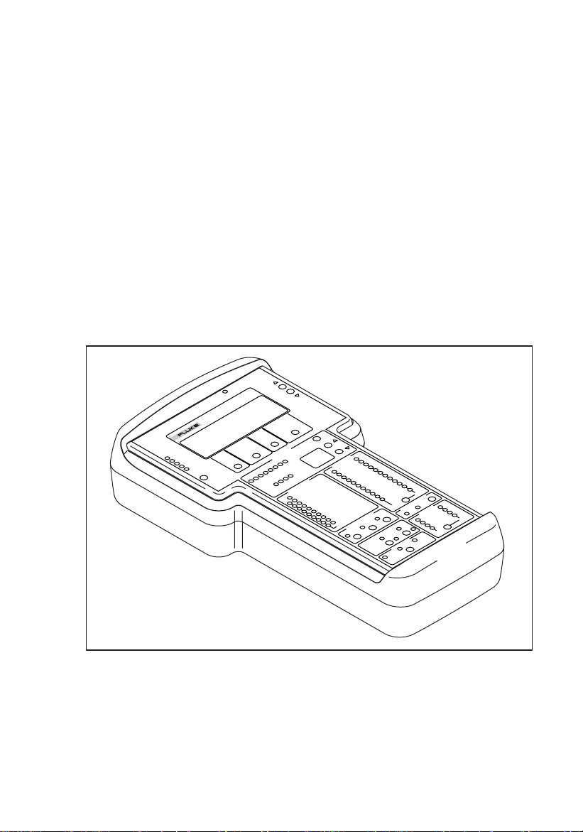
1-1. QuickBERT-T1 Test Set.................................................................... 1-1
1-2. Supplied Equipment........................................................................... 1-4
1-3. ToolPak Accessory Kit ...................................................................... 1-5
2-1. QuickBERT-T1 Front Panel.............................................................. 2-3
2-2. QuickCHECK-T1 Front Panel........................................................... 2-4
3-1. Live-Traffic Monitoring..................................................................... 3-3
3-2. Capturing and Displaying DTMF Digits............................................ 3-6
3-3. Performing an Out-of-Service BERT................................................. 3-7
3-4. Performing an End-to End, Out-of-Service BERT ............................ 3-9
3-5. Clock-Slip Measurements.................................................................. 3-11
vii
Page 10

635/633
Users Manual
viii
Page 11
Chapter 1
Introduction
1-1. Introduction
This chapter of the manual contains general information about the Fluke 635
QuickBERT-T1 and 633 QuickCHECK-T1. These units are compact,
handheld, fully-featured T1 test sets designed to thoroughly verify the
performance parameter of a T1 facility.
LOW BATTERY
RESULTS
ERRORS
BIT ERR
BPV ERR
FRM ERR
635 QUICKCHECK - T1
CRC ERR
FREQDEV
RESTART
SIGNALING
TEST
MODE
LOOP
CODE
TxClk
SOURCE
DATA BITS
1234
CHANNEL
5678
SIGNALING BITS
ABCD
FT1 CHANNEL
SELECT
Rx STATUS
AMI
B8ZS
SIGNAL PRESENT
OUT OF FRAME
BLUE ALARM (AIS)
ONES DENSITY
EXCESS ZEROS
TYPE
Figure 1-1. QuickBERT-T1 Test Set
PATTERN
QRSS
YELLOW ALARM
DS1 IDLE SIGNAL
PATTERN SYNC LOSS
HISTORY
1 IN 7
2 IN 8
3 IN 24
ERROR INJECT
LOGIC
ALL 0'S
ALL 1'S
BPV FRAME
RECEIVE
1 : 1
NET55
OCT55
DALY55
USER
LOOP UP LOOP DOWN
SEND
DSX
MON
THRU
RX
Rx INPUT
TX
Tx LINE CODE
AMI
BRDG
TERM
B8ZS
FRAME
NONE
D4
TX
ESF
SLC96
RX
abn05f.eps
1-1
Page 12

633/635
Users Manual
1-2. Design Highlights
The QuickBERT-T1 and QuickCHECK-T1 are designed to allow users to
easily analyze and correct the common problems arising in T1 networks.
Experienced and inexperienced users alike can determine the integrity,
configuration parameters, and general performance of a T1 circuit when using
these units. Features include the following.
•
Is handheld and battery powered
•
Transmits all standard T1 bit error rate test (BERT) patterns and loop
codes (QuickBERT-T1 only)
•
Transmits HDSL loop codes (QuickBERT-T1 only)
•
Has the ability to insert logic, BPV, and frame bit errors (QuickBERT-T1
only)
•
Performs BERT and Fractional T1 BERT (Nx56 and Nx64)
•
Captures and displays DTMF digits
•
Measures DS1 frequency, level, and clock slips
•
Displays standard T1 alarms
•
Displays major T1 performance parameters
•
Displays AMI or B8ZS line coding
•
Measures DS 0 level and frequency
•
Monitors voice using internal speaker (or headset)
•
Displays DS0 data and signaling bits
•
Automatically synchronizes to and displays the T1 framing type, line
coding, and BERT pattern
1-2
Page 13

Introduction
Safety Information
1-3. Safety Information
W Warnings and Precautions
To avoid possible electric shock or personal injury, and to
avoid possible damage to the Test Set or to the equipment
under test, follow these guidelines:
•
Before using the Test Set inspect the case. Do not use the Test Set if it is
damaged.
•
Inspect the test cables for damaged in sulation or exposed metal. Check the
cables for continuity. Replace damaged test cables, before using the Test
Set.
•
Do not operate the Test Set around explosive gas, vapor, or dust.
•
Do not operate the Test Set with the case (or part of the case) removed.
•
Recharge the battery as soon as the low battery indicator appears. With a
low battery, the Test Set might produce false readings.
•
When servicing the Test Set, use only specified replacement parts.
1
1-4. Software Revision
To view the software revision number and the date of release, press and hold
RESTART
the
key while powering up the unit.
1-5. Self Test
After the startup screen, a self test will activate and the version build date will
be displayed. To perform an LED test, press and hold the
while powering up the unit.
RX INPUT
key
1-3
Page 14

633/635
Users Manual
1-6. Supplied Equipment
The QuickBERT-T1 and QuickCHECK-T1 come with the following items.
•
Carrying case
•
ToolPak
•
A/C power adapter
•
Two bantam-to-bantam cables
•
Users manual
•
Trimmer tool (used to adjust display view angle)
The 635-1 version of the QuickBERT-T1 also comes with a cable kit, which
includes the following items.
•
Two bantam-to-310 cables
•
Two bantam-to-alligator clip cables
•
One bantam-to-RJ48 cable.
TM
Accessory Kit
A/C Power Adapter
Bantam-toBantam Cables
1-4
ToolPack
Users Manual
Figure 1-2. Supplied Equipment
Carrying Case
abn01f.eps
Page 15
Introduction
Toolpak Accessory Kit
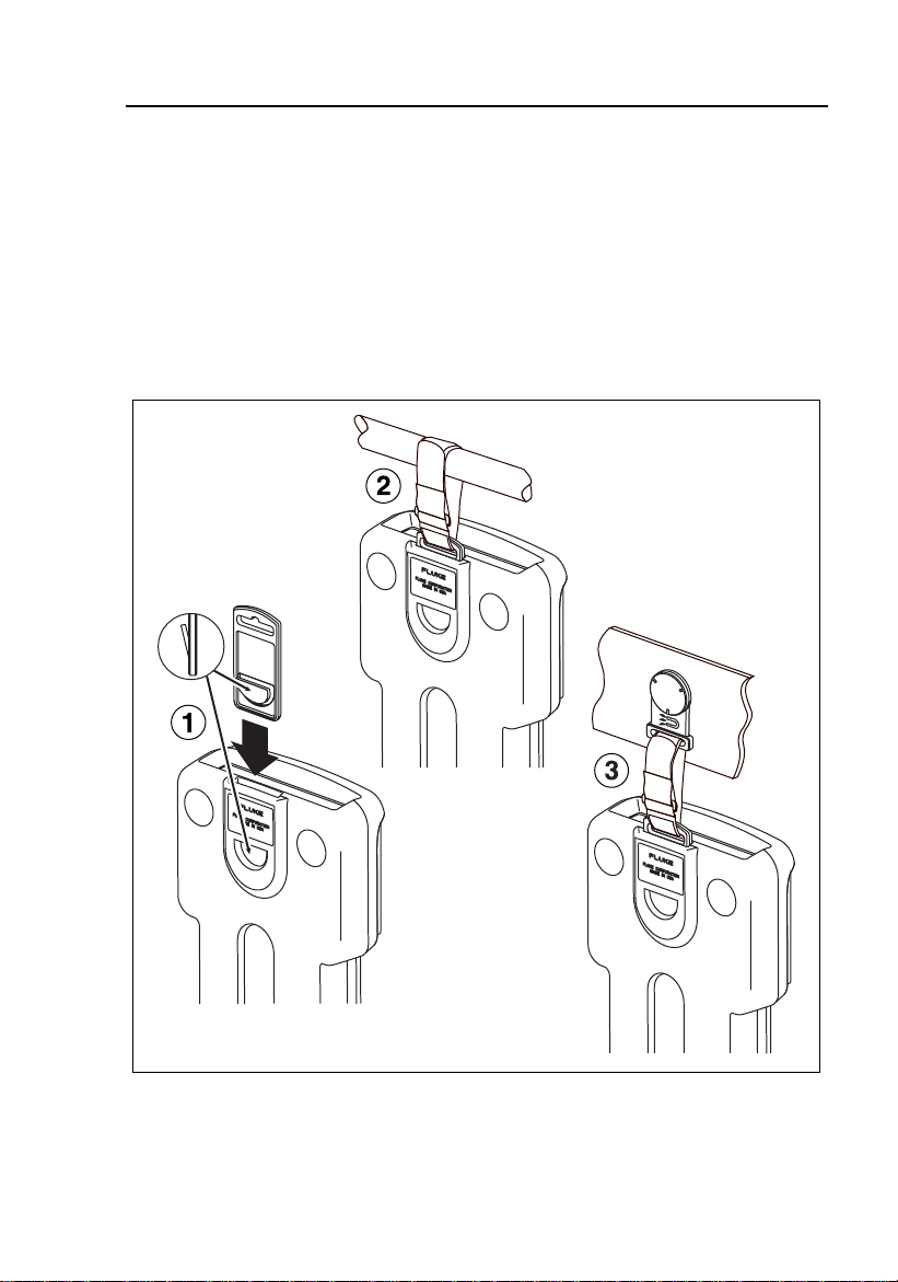
1-7. Toolpak Accessor y Kit
The QuickBERT-T1 and QuickCHECK-T1 come with a ToolPak accessories
kit. This kit includes a universal hanger, hook-and-loop straps, and a magnet.
The universal hanger attaches to the unit and can be used by itself on a nail or
hook, with a piece of rope or stiff wire. Two hook-and-loop straps are used
with the universal hanger and can be wrapped around a pipe or beam. The
ToolPak’s magnet is used with the universal hanger and is strong enough to
securely hold the test set.
Hanger inserts
into slot with tab
extension facing
out, for proper use.
1
Figure 1-3. ToolPak Accessory Kit
abn03f.eps
1-5
Page 16

633/635
Users Manual
1-8. View Angle Adjustment
VIEW ANGLE
The
recessed control used to vary the display’s view angle.
In order to prevent damage to the test set, use only an isulated, flat-
bladed tool to adjust the display’s view angle.
control, located on the top panel of the test set, is a
Note
1-9. Accessories
Additional cables and headsets for use with the Q uickBERT-T1 and
QuickCHECK-T1 are available from Fluke Corporation. For information,
please contact customer service at 888-993-5853.
1-10. Cleaning
When cleaning the display surface, use a soft cloth (such as a gauze) with mild
soap and water.
1-11. Environmental
Do not exceed the operating temperature limits of 32° to 122° F. Protect your
unit from exposure to direct sunshine or high temperature/humidity for
prolonged periods of time. These conditions may cause degradation to t he
display.
1-12. Manual
This manual is arranged so you can quickly and easily find the information you
need. The following is an overview of the contents of this manual.
•
Chapter 1, Introduction, familiarizes you with QuickBERT-T1 and
QuickCHECK-T1 highlights.
• Chapter 2, Overview, describes the QuickBERT-T1 and QuickCHECK-T1
controls, indicators, and connectors.
• Chapter 3, Operation, provides common test i nstructions.
1-6
Page 17

Introduction
Manual
•
Appendix A, Specifications, provides the specifications of the
QuickBERT-T1 and QuickCHECK-T1.
References to front panel keys are designated in upper case bold letters.
1
1-7
Page 18

633/635
Users Manual
1-8
Page 19

Chapter 2
Overview
2-1. Introduction
This chapter of the manual contains information to familiarize you with
QuickBERT-T1 and QuickCHECK-T1 controls and indicators. Refer to
Appendix A for test set specifications. Figure 2-1 and 2 -2 illustrate all control
and indicator locations.
2-2. Power
The primary power source for the QuickBERT-T1 and QuickCHECK-T1 is a
rechargeable, NiMH (nickel metal hydride) battery pack. An auxiliary power
connector is available for use with an A/C power adapter (which is provided
with the unit). The
jack and the RX bantam jack on the top panel of the unit. During battery
operation, the LOW BATTERY LED will illumi nate to indicate that the
battery pack has nearly exhausted its charge and that the test set should be
recharged.
If the test set is not turned off before the battery is co mpletely
exhausted, the unit will shut down to prevent battery damage. If this
occurs, the unit will resume normal operation once recharge is
performed.
ON/OFF
switch is located between the power (9 VDC)
Note
2-3. Primary And Reference T1 Receivers
The QuickBERT-T1 and QuickCHECK-T1 are equipped with two T1
receivers: primary (Rx) and reference (REF). The test set performs analysis on
the signal present at the Rx receiver. The REF receiver provides the clock
reference for performing clock-slip measurements.
On the QuickBERT-T1, the REF receiver functions as the transmit clock
source when external (EXT) clock is selected. For additio nal information on
clock-source selection, see section 2-18.
2-1
Page 20

633/635
Users Manual
RX INPUT
The
connection from a T1 line to the RX jack, the
appropriately. For additional information on the
settings, see section 2-42.
A bantam jack is provided for the REF T1 receiver. This jack is automatically
terminated by the test set.
key is provided for the Rx T1 receiver. Before making a
RX INPUT
RX INPUT
key should be se t
key and its
2-4. Controls
The QuickBERT-T1 is equipped with 19 pushbutton keys and one switch. The
TX PATTERN, TX LINE CODE
RESTART
The QuickCHECK-T1 is equipped with 9 pushbutton keys and one switch. The
RESTART
The following is a list of the controls which are defined in sections 2-5 through
2-58. An asterisk is placed next to those controls that are only applicable to the
QuickBERT-T1. The remaining controls are included on both units.
key is red. All remaining pushbutton keys are black.
key is red. All remaining pushbutton keys are black.
ON/OFF Switch CHANNEL UP/DOWN Keys
RESULTS Keys ERROR INJECT Keys*
TX FRAMING
, and
keys are yellow. The
RESTART Key SEND LOOP UP/DOWN Keys*
TEST MODE Key RX INPUT Key
SIGNALING TYPE Key TX PATTERN Key*
TXCLK SOURCE Key* TX LINE CODE Key*
LOOP CODE Key* TX FRAME Key*
FT1 CHANNEL SELECT Key Volume Control
2-5. ON/OFF Switch
This switch is located on the top panel of the test set and is used to apply and
remove power from the unit.
2-2
Page 21

ERRORS
BIT ERR
BPV ERR
FRM ERR
CRC ERR
FREQDEV
RESTART
635 QUICKBERT - T1
TEST
SIGNALING
MODE
DATA BITS
1234
SIGNALING BITS
ABCD
Rx STATUS PATTERN
AMI
B8ZS
SIGNAL PRESENT
OUT OF FRAME
BLUE ALARM (AIS)
ONES DENSITY
EXCESS ZEROS
YELLOW ALARM
DS1 IDLE SIGNAL
PATTERN SYNC LOSS
HISTORY
ERROR INJECT
LOGIC
BPV FRAME
LOOP UP LOOP DOWN
RECEIVE
SEND
Rx INPUT
DSX
MON
TYPE
CHANNEL
5678
TERM
BRDG
TxClk
SOURCE
FT1 CHANNEL
SELECT
QRSS
1 IN 7
2 IN 8
3 IN 24
ALL 0'S
ALL 1'S
1 : 1
NET55
OCT55
DALY55
USER
THRU
RX
Tx LINE CODE
AMI
FRAME
NONE
D4
ESF
SLC96
RX
LOOP
CODE
B8ZS
LOW BATTERY
TX
TX
RESULTS
Overview
Controls
2
Figure 2-1. QuickBERT-T1 Front Panel
abn02f.eps
2-3
Page 22

633/635
Users Manual
ERRORS
BIT ERR
BPV ERR
FRM ERR
CRC ERR
FREQDEV
RESTART
633 QUICKCHECK - T1
TEST
SIGNALING
MODE
TYPE
CHANNEL
DATA BITS
12345678
SIGNALING BITS
ABCD
Rx STATUS PATTERN
AMI
B8ZS
SIGNAL PRESENT
OUT OF FRAME
BLUE ALARM (AIS)
ONES DENSITY
EXCESS ZEROS
YELLOW ALARM
DS1 IDLE SIGNAL
PATTERN SYNC LOSS
HISTORY
FT1 CHANNEL
SELECT
QRSS
1 IN 7
2 IN 8
3 IN 24
ALL 0'S
ALL 1'S
1 : 1
NET55
OCT55
DALY55
RX
LOW BATTERY
RESULTS
2-4
FRAME
NONE
D4
DSX
MON
Rx INPUT
TERM
BRDG
ESF
SLC96
RX
Figure 2-2. QuickCHECK-T1 Front Panel
abn04f.eps
Page 23

Overview
Controls
2
2-6. RESULTS Keys
These keys are used to scroll through the paired results parameters that appear
on the display screen. To go from one pair of results to the next, use the
RESULTS UP/DOWN
BPV Error 0
Frame Err 0
T1 RB Int CSU
The five Error LEDs will illuminate solid if currently detecting an error and
will flash to indicate an error has previously been detected but is not currently
being detected (history). Sections 2-7 through 2-14 provide detailed
descriptions of the paired parameters.
keys (located to the right of the display screen).
abn06f.eps
2-7. BPV Error/Frame Err
BPV Error 0
Frame Err 0
T1 RB Int CSU
abn07f.eps
BPV Error
The test set records a bipolar violation (BPV) if it detects a vio lation of the
alternate mark inversion (AMI) line-coding scheme (that is standard for T1
transmission). BPVs are recorded if the T1 signal is live traffic or a B ERT
pattern. The red BPV ERR LED will illuminate solid to indicate a BPV error is
present and will flash to indicate a history of BPV errors.
Frame Err
The test set automatically synchronizes with D4, ESF, o r SLC¨96 framing.
When frame synchronization is achieved, the proper green Frame LED will
illuminate. The unit will now register a ny errors that occur in the framing bit
sequence (as defined for that particular framing format). Frame errors are
recorded if the T1 signal is live traffic or a BERT pattern. The red FRM ERR
2-5
Page 24

633/635
Users Manual
LED will illuminate solid to indicate a frame error is present and will flash to
indicate a history of frame errors.
2-8. CRC Error/Bit Error
BPV Error 0
Frame Err 0
T1 RB Int CSU
abn07f.eps
CRC Error
If the test set establishes frame sync with an ESF-framed signal, it will detect
and count cyclic redundancy check (CRC) errors. The CRC is a check-sum
message that is transmitted in the facility data link (FDL) associated with ESF
framing. The red CRC ERR LED will illuminate solid to indicate a CRC erro r
is present and will flash to indicate a history of CRC errors.
Bit Error
In order to record a bit error, the test set has to be synchronized with a test
pattern. Therefore, bit errors are registered only if a BERT pattern is present.
Pattern synchronization is indicated by the green Pattern LEDs. Each time the
unit detects an errored bit in the pattern it is receiving, one bit error is recorded.
The red BIT ERR LED will illuminate solid to indicate a bit error is present
and will flash to indicate a history of bit errors.
2-6
Page 25

Overview
Controls
2
2-9. DS1 Freq/Clk Slips
DS1 Freq 1544000Hz
Clk Slips 0
T1 RB Int CSU
abn09f.eps
DS1 Freq
When the DS1 frequency result is selected (using the RESULTS keys), the test
set displays the frequency (in Hz) of the DS1 signal. If the DS1 frequency
deviates from the nominal (1.544 MHz ± 50 Hz), the red FREQDEV LED
illuminates to indicate that a DS1 frequency deviation is occurring. A
frequency deviation of greater than ± 50 Hz indicates that the clock source is
becoming unstable and has an unacceptable variation.
Clk Slips
In order for a T1 circuit to perform properly, the TX clock (from the CPE)
must be synchronized with the receive clock (from the central office). If a
variation of these clocks exists, errors will result. The clock-slip parameter is
used to verify clo ck synchroniza tion. The test setup for a clock-sli p
measurement between the Tx and Rx side of a T1 span is described in section
3-10 of this manual.
Timing tests may also be performed to either side of the span when a T1
reference clock (stratum) is used. If a bipolar clock or a T1 signal is present at
both the REF and RX receivers, the test set compares the two inputs and
declares clock slips (if they are out of phase). If an external reference clock is
not available, the unit will automatically compare the receiver clock to the
internal, 5-ppm, 1.544-MHz clock source.
Clock slips is a loop-timing parameter that shows the total number of clock
counts that the reference and receiver clocks have deviated from since the test
began (or from the last restart). A positive number indicates that the reference
clock is faster than the receive clock. A negative number indicates that the
receive clock is faster than the reference clock.
2-7
Page 26

633/635
Users Manual
Note
If no reference clock measurement is being made, remove the plug
from the REF jack to extend battery life.
2-10. E-Bit Sync
E-Bit Sync Yes
T1 E-Bit Int CSU
abn10f.eps
If E-Bit is the selected signaling type (chosen with t he
SIGNALING TYPE
key), the E-Bit Sync results screen will display Yes or No to indicate whether
or not the span is in E-Bit sync. If E-Bit is not the selected signaling type, the
E-Bit Sync results screen is not accessible.
2-11. DS1 Level (volts, peak-to-peak)/DS1 Level (dBDSX)
DS1 Level 6.00vp-p
DS1 Level 0.00dBD
T1 RB Int CSU
abn10f.eps
DS1 Level (volts, peak-to-peak)
When monitoring an in-service span, it may be useful to read the level o f the
T1 signal in volts, peak-to-peak; therefore, the DS1 level may be viewed both
in dBDSX and volts, peak-to-peak. See section 3-6.
2-8
Page 27

DS1 Level (dBDSX)
Overview
Controls
2
When the DS1 level result is selected (using the
displays the level of the DS1 signal in dBDSX. A DS1 signal is transmitted at
a 0 dBDSX level. The reading, therefore, indicates the loss (in dB) from the
point of transmission to the point of measurement.
RESULTS
keys), the test set
2-12. DS0 Freq/DS0 Level
DS0 Freq 1004.0Hz
DS0 Level 0.0dBm
T1 RB Int CSU
abn12f.eps
DS0 Frequency
DS0 frequency is a measurement of the analog frequency for the DS0 that is
currently being monitored. For example, a test tone that is being received (in
the selected DS0) will be measured and the received frequency will be
displayed. The test set demodulates the digitally-encoded signal on t he selected
channel and presents it through the speaker (and the headset jack). If the DS0
frequency result is selected (using the
analog signal present on the channel i s displayed in Hz. (This result display is
only available if a channel has been selected for monitoring.)
RESULTS
keys), the fr equency of the
DS0 Level
DS0 level is a measurement of the analog signal level for the DS0 that is
currently being monitored. For example, a test tone that is being received will
be measured and the received level (or amplitude) will be displayed. The test
set demodulates the digitally-encoded signal on the selected channel and drops
the channel to the speaker (and the headset jack). If the DS0 level result is
selected (using the
dBm. If you know the level at which the tone signal is inserted, the insertion
loss of the channel may be determined. (This result display is only available if
a channel has been selected for monitoring.)
RESULTS
keys), the level of the signal is displayed in
2-9
Page 28

633/635
Users Manual
Note
The test set develops the analog signal level from the decoded digital
signal. Therefore, the isolation resistors at a DSX monitor jack do not
affect eh DSO-level reading. See the note under step 7b in section 3-6.
2-13. FT1 (Fractional T1)
FT1 01 02 03 04 05
06 07 08 09 10 11 12
F64 CCIS Rx CSU
abn13f.eps
If F64 or F56 is selected as the test mode, you can view the Fractional T1
channels (01-24) on the FT1 results screens. There are two FT1 results screens:
one with channels 01-12 and one with channels 13-24. The selected channel(s)
will blink. For information on how to select channels for Fractional T1, see
section 2-38.
2-14. DTMF
DTMF - - No Digits - -
F64 CCIS Rx CSU
abn14f.eps
The DTMF results screen allows you to view DTMF digits for a selected
channel. For information on how to capture and display DTMF digits, see
section 3-7. (This result display is only available if a channel has been selected
for monitoring.)
2-10
Page 29

Overview
Controls
2-15. RESTART Key
Bit errors, BPV errors, CRC errors, frame errors, clock slip s, and errored
seconds are cleared to "0" when the
results is being displayed when the
to be displayed, but "0" will be displayed until an error of that type occurs.
Any red Error LEDs that are flashing (to indicate errors of that type) will be
turned off when the
are cleared when the
Always press the RESTART key after connecting the test set to the
line under test. The unit might detect invalid errors when first
connected due to receiver sensitivity.
RESTART
RESTART
RESTART
RESTART
key is pressed. All Status and History LEDs
key is pressed.
Note
key is pressed. If one of these
key is pressed, it will continue
2
Pressing the
Bits LEDs, Signaling Type LEDs, LOW BATTERY LED, or Channel
Selection display. In addition, pr essing the
to enter the auto-evaluate mode (see section 3 -2 for ad ditional information on
automatic evaluation).
RESTART
key does not af fect the Signalin g Bits LEDs, Data
RESTART
key causes the test set
2-16. TEST MODE Key
TEST MODE
The
(fractional T1, 64k), or F56 (fractional T1, 56k). W hen the T1 mode is
selected, you can perform a T1 in-service or out-of-service BERT. For both the
F64 and F56 test modes, the receiver performs T1 in-service or out-of-service
testing on only the active channels and ignores the data on all other channels.
When F64 mode is selected, all 8 bits in each active channel are used by the
receiver for BERT. When the F56 mode is selected, only the first 7 bits in each
active channel are used by the receiver for BERT.
The transmitter (QuickBERT-T1 only) sends the BERT pattern on the active
channel(s). The received signal is simply passed through in the inactive
channels and if there is not a received signal present, the inactive channels are
filled with idle code (FF Hex). (Channels can be selected with the
CHANNEL SELECT
key allows you to select one of three test modes: T1, F64
FT1
key.)
2-11
Page 30

633/635
Users Manual
2-17. SIGNALING TYPE Key
When the test set is in frame sync, either the D4, ESF, or SLC96 green
Framing LED illuminates. For further analysis, the unit provides the abilit y to
view the state of the signaling bits and data bits for a selected DS0 channel.
There are four yellow Signaling Bits LEDs provided for this purpose (A, B, C,
D). The D4 and SLC96 framing modes make provision for two signaling bits
(A, B). The ESF framing mode makes provisio n for four signaling bits (A, B,
C, D). In order to display the state of the signaling bits, the test set must be set
up for the proper signaling format (robbed bit, CCIS, or E-Bit) being used on
the T1 line under test.
The robbed bit (RB) scheme uses "robbed" data bits to transmit the signaling
states. In common channel interoffice signaling (CCIS), a complete channel
(DS0) is used to transmit signaling bits, thu s leaving the eight data bits
available to transmit data (clear channel). The E-Bit selection is p r ovided to
define a proprietary common channel signaling scheme.
2-18. TX CLK SOURCE Key (QuickBERT-T1 only)
This key is used to select one of three transmit clock sources: Rx (recovered),
Int (internal), and Ext (external). When Rx is selected, the QuickBERT-T1
recovers the clock from the received bit stream and uses the received clock as
the timing element for the transmit data. When Int is selected, the 1.544 MHz
internal oscillator is used to clock the transmitter. When Ext is selected, the
QuickBERT-T1 recovers the bipolar clock from the external clock that is
applied to the REF bantam jack and uses this clock as the transmit timing
element.
2-19. LOOP CODE Key (QuickBERT-T1 only)
This key is used to select the type of loop code to be transmitted by the
QuickBERT-T1. See Table 2-1 for a list of the codes transmitted by the
QuickBERT-T1 when the corresponding selections are made and the
LOOP UP
either ADTRAN, Inc. or PairGain Technologies, Inc. loop codes. Sections 2-20
through 2-37 provide detailed descriptions of the loop-code types.
2-12
SEND LOOP DOWN
or
key is pressed. The HDSL loop codes are
SEND
Page 31

Table 2-1. Loop Code Types
Overview
Controls
2
Loop Code
Loop-Up Code Loop-Down Code
Type
CSU 10000 (IN-BAND) 100 (IN-BAND)
NIU4 1100 (IN-BAND) 1110 (IN-BAND)
NIU5 11000 (IN-BAND) 11100 (IN-BAND)
NTWRK (ESF) 11111111010010 00 (OU T-B AN D ) 11111111001001 00 (OU T-B AN D )
LINE (D4) 10000 (IN-BAND) 100 (IN-BAND)
LINE (ESF) 1111111101110000 (OUT-BAND) 1111111100011100 (OUT-BAND)
PYLD (ESF) 11111111001010 00 (OU T-B AN D ) 11111111010011 00 (OU T-B AN D )
ARM 11000 (IN-B AN D) 11100 (IN-BAN D)
HTU-R 11000111010000 10 (IN-B AN D ) 10010011100100 11 (IN-B AN D )
HTU-C 11010011110100 11 (IN-B AN D ) 10010011100100 11 (IN-B AN D )
HRE1 11000111010000 01 (IN-B AN D ) 10010011100100 11 (IN-B AN D )
HRE2 11000111010101 00 (IN-B AN D ) 10010011100100 11 (IN-B AN D )
NREM 11111111000000 10 (IN-B AN D ) 11100 (IN-BAND)
NLOC 11111111000111 10 (IN-B AN D ) 11100 (IN-BAND)
NDU1 1111111100000100 (IN-BAND) 11100 (IN-BAND)
NDU2 1111111100000110 (IN-BAND) 11100 (IN-BAND)
CREM 00111111000111 10 (IN-B AN D ) 11100 (IN-BAND)
CLOC 00111111000000 10 (IN-B AN D ) 11100 (IN-BAND)
CDU1 0011111100000100 (IN-BAND) 11100 (IN-BAND)
CDU2 0011111100000110 (IN-BAND) 11100 (IN-BAND)
2-13
Page 32

633/635
Users Manual
2-20. CSU
This selection is made to loop up/down a CSU, typically on the far end of a T1
span (see Chapter 3).
2-21. NIU4, NIU5
This selection is made to loop an NIU. The NIU (sometimes called smart jack)
is part of the network equipment and belongs to the service provider. Most
modern NIUs respond to the NIU5 code. Older NIUs only respond to the NIU4
code.
2-22. NTWRK
This selection is only valid in ESF framing. The NTWRK loop code is
transmitted "out of band" (in the facilit y data link (FDL) of the ESF signal).
The distant ESF CSU will respond by looping the DS1 signal back at a point
that includes the entire CSU. The NTWRK loop code may be used in
conjunction with the LINE loop code to determine whether a fault exists in the
facility or the CSU. In order to activate the NTWRK loop code, ESF framing
must be selected (using the
TX FRAME
key).
2-23. LINE
If ESF framing and LINE loop code are selected, pressing the
UP
SEND LOOP DOWN
or
the FDL of the ESF signal). The distant ESF CSU will respond by looping the
entire DS1 signal at a point that does not include the CSU circuitry. The LINE
loop code may be used in conjunction with the NTWRK loop code to
determine whether a fault exists in the facility or the CSU. The LINE loop
code may also be sent in band when D4 framing is selected.
key will transmit LINE code "out of band" (in
SEND LOOP
2-24. PYLD
If ESF framing and PYLD loop code are selected, pressing the
UP
SEND LOOP DOWN
or
(in the FDL of the ESF signal). The distant ESF CSU will respond by looping
only the payload (the customer data) of the ESF signal. The FDL will not be
looped back, as with the NTWRK or the LINE loop codes. Because the FDL
isregenerated at the distant CSU, the PYLD loop code is useful in determining
which side of a T1 facility is faulty.
2-14
key will transmit the PYLD code "out of band"
SEND LOOP
Page 33

2-25. ARM (ADTRAN)
Overview
Controls
2
When ARM is selected and the
ADTRAN HDSL equipment is armed, enabling the HDSL elements to be
looped. When ARM is selected and the
all ADTRAN HDSL equipment is disarmed.
SEND LOOP UP
SEND LOOP DOWN
key is pressed, all
key is pressed,
2-26. HTU-R (ADTRAN)
This selection causes the HTU-R (remote-end HDSL unit) to transition from an
armed state to a loopback state.
2-27. HTU-C (ADTRAN)
This selection causes the HTU-C (central -office HD SL unit) to transition from
an armed state to a loopback state.
2-28. HRE1 (ADTRAN)
This selection causes the HRE1 (HDSL range extender 1; sometimes referred
to as a "doubler") to transition from an armed state to a loopback state.
2-29. HRE2 (ADTRAN)
This selection causes the HRE2 (HDSL range extender 2; sometimes referred
to as a "doubler") to transition from an armed state to a loopback state.
2-30. NREM (PairGain)
This selection causes the NREM (network remote) to transition to a loopback
state.
2-31. NLOC (PairGain)
This selection causes the NLOC (network local loop) to transition to a
loopback state.
2-32. NDU1 (PairGain)
This selection causes the NDU1 (network doubler 1) to transition to a loopback
state.
2-33. NDU2 (PairGain)
This selection causes the NDU2 (network doubler 2) to transition to a loopback
state.
2-15
Page 34

633/635
Users Manual
2-34. CREM (PairGain)
This selection causes the CREM (customer remote) to transition to a loopback
state.
2-35. CLOC (PairGain)
This selection causes the CLOC (customer local loop) to transition to a
loopback state.
2-36. CDU1 (PairGain)
This selection causes the CDU1 (customer doubler 1) to transition to a
loopback state.
2-37. CDU2 (PairGain)
This selection causes the CDU2 (customer doubler 2) to transition to a
loopback state.
2-38. FT1 CHANNEL SELECT Key
When in F64 or F56 test mode, the FT1 channels will be selected by scrolling
through the DS0s using the
two-character display. To select the displayed channel for F64 or F56 BERT,
press the
on the display screen (shown below) if FT 1 is selected as the result type (using
the
FT1 CHANNEL SELECT
RESULTS
keys).
CHANNEL UP/DOWN
key. The selected channel(s) will blink
keys and vie wing the
FT1 01 02 03 04 05
06 07 08 09 10 11 12
F64 CCIS Rx CSU
abn15f.eps
To clear or deselect all channels for F64 or F56 BERT, select no channel
(shown as "--" on the two-character display). Then, press the
SELECT key momentarily. To select all channels, press and hold the FT1
CHANNEL SELECT key for approximately two seconds.
FT1 CHANNEL
2-39. CHANNEL UP/DOWN Keys
These keys are used to select the DS0 channel for data and signaling drop to
the Signaling Bits and Data Bits LEDs. The selected DS0 will also be dropped
2-16
Page 35

Overview
Controls
to the speaker (and headset jack). The DS0 channel selection (1-24) is shown
on the display that is located to the left of the
These keys are also used with Fractional T1 to select fractional channels.
CHANNEL UP/DOWN
keys.
2-40. ERROR INJECT Keys (QuickBERT-T1 only)
2
The three
errors into the data stream. When you press the
momentarily, the LED will flash and one error will be injected. When you
press and hold the
LED will illuminate solid and the selected error will be injected at an error rate
of 1.0E-4. Pressing the
inject rate and turn the LED off.
ERROR INJECT
ERROR INJECT
ERROR INJECT
keys allow insertion of logic, BPV, or frame
ERROR INJECT
key for approximately two seconds, the
key again will discontinue the error
key
2-41. SEND LOOP UP/DOWN Keys (QuickBERT-T1
only)
Various circuit elements in a T1 span respond to loop codes. This allows one
person to perform an out-of-service BERT. Press the
transmit the loop-up code (which has been selected by the
The SEND LOOP UP LED will illuminate to indicate the code is b eing
transmitted. Once the device is looped, the RECEIVE LOOP UP LED will
illuminate for approximately 3 seconds (5 seconds for HDSL loop codes) to
indicate that the device has successfully looped up. Press the
DOWN
LOOP CODE
indicate the code is being transmitted. The RECEIVE LOOP DOWN LED will
illuminate for approximately 3 seconds (5 seconds for HDSL loop codes) to
indicate that the device has successfully looped down. Table 2-1 lists all of the
loop-code types supported by the QuickBERT-T1. When monitoring a span, if
the QuickBERT-T1 detects a loop code, the RECEIVE LOOP UP LED will
illuminate to indicate a pre-loop condition.
key to transmit the loop-down code (which has been selected by the
key). The SEND LOOP DOWN LED will illuminate to
SEND LOOP UP
LOOP CODE
SEND LOOP
key to
key).
2-42. RX INPUT Key
Before making a connection to the RX jack, the
appropriately. This key allows you to choose between three different T1
terminations: DSX MON for monitoring in-service or out-of-service lines
through a DSX Monitor jack; TERM typically for out-of-service testing; and
BRDG for monitoring in-service or out-of-service lines. The following
paragraphs describe each termination mode.
RX INPUT
key should be set
2-17
Page 36

633/635
Users Manual
DSX MON - The DSX Monitor Mode is typically used to monitor in-service
T1 spans through a DSX monitor jack that is resistor-isolated from the span.
When DSX MON is selected, the receiver is terminated into 100 ohms. Due to
the loading effect of the 100-ohm termination in series with the isolation
resistors, there is approximately a 20 dB line drop seen by the receiver. See
Chapter 3.
TERM - The Terminate Mode is used when the span is being terminated by the
QuickBERT-T1 or QuickCHECK-T1. It is typically used for an out-of-service
BERT (see section 3-8).
BRDG - The Bridge Mode is typically used to monitor in-service T-spans that
do not have a DSX monitor jack. The test set assumes a bridged connection
consists of a direct connection to one side of the span, and that the connection
is not resistor-isolated to the receive connector of the test set. The receiver is
set to the high-impedance state of greater than 1000 ohms.
2-43. TX PATTERN Key (QuickBERT-T1 only)
TX PATTERN
The
transmitted by the QuickBERT-T1. Twelve patterns are available for selection.
The yellow Pattern LEDs illuminate to indicate that t he corresponding pattern
is being transmitted. To change the pattern, s imply press the
key.
key controls the data content of the signal being
TX PATTERN
Since the transmitter and receiver of the QuickBERT-T1 are totally
independent, the pattern being transmitted is not necessarily the pattern being
received. So while the yellow Pattern LEDs indicate the pattern being
transmitted, the green Pattern LEDs indicate the pattern being received. No
selection is necessary for the received pattern.
The QuickBERT-T1 automatically evaluates the signal present at the receiver
and the appropriate LED illuminates ind icating pattern synchronization has
been achieved. Sections 2-44 through 2-55 provide detailed descriptions of the
individual patterns.
2-44. QRSS
The quasi-random signal source (QRSS) pattern is modified 220-1
pseudorandom pattern which allows a maximum of 14 sequential zeros and 20
sequential ones. The QRSS pattern is the most widely used pattern to test DS1
facilities. It provides a random set of stresses including long strings of zeros
and ones. Unless B8ZS is invoked, QRSS violates the ones-density
requirements when framed.
2-18
Page 37

Overview
Controls
2
2-45. 1 IN 7
This pattern is a sequence of a one and seven zeros in the following form: 0100
0000. The maximum number of sequential zeros is eight, when transmitted
framed, and seven when transmitted unframed. This pattern is useful when
testing for mis-optione d AMI /B 8ZS eq uipment.
2-46. 2 IN 8
This pattern is a sequence of two ones in eight bits in the following form: 0100
1000. The maximum number of sequential zeros is four, either framed or
unframed. This pattern is used to verify error-free transmission in B8ZSoptioned systems.
2-47. 3 IN 24
This pattern is a sequence of three ones in 24 bits in the following form: 0100
0100 0000 0000 0000 0100. The maximum number of sequential zeros is 15.
This pattern is used to stress timing recovery in AMI-optioned systems.
2-48. ALL 0’S
This pattern is a sequence of all zeros. This pattern is useful for testing B8ZS
circuits.
2-49. ALL 1’S
This pattern is a sequence of all ones. “All ones” require the maximum power
to regenerate. This pattern is used to make loss measurements of the DS1
signal.
2-50. 1:1
This pattern is a sequence of alternating ones and zeros.
2-51. NET55
This pattern is a repeating pattern of 55 bytes according to the following
hexadecimal sequence.
01 01 03 01 01 01 00 01 01 01 01 01 01 03 01 01 01 01 07 01
01 01 01 55 55 55 55 AA AA AA AA 01 01 01 01 01 01 FF FF FF
FF FF FF 80 01 80 01 80 01 80 01 80 01 80 01
This pattern creates a variety of stress on the circuits. Some service providers
require end-to-end testing using the 55 patterns.
2-19
Page 38

633/635
Users Manual
2-52. OCT55
This pattern is a modified 220-1 pseudorandom pattern which allows a
maximum number of 14 sequential zeros and 20 sequential ones.
01 01 01 01 01 01 00 01 01 01 01 01 01 03 01 01 01 01 07 01
01 01 01 55 55 55 55 AA AA AA AA 01 01 01 01 01 01 FF FF FF
FF FF FF 80 01 80 01 80 01 80 01 80 01 80 01
This pattern creates a variety of stress on the circuits. Some service providers
require end-to-end testing using the 55 patterns.
2-53. DALY55
This pattern is a repeating pattern of 55 bytes according to the following
hexadecimal sequence.
01 01 01 01 01 01 80 01 01 01 01 01 01 03 01 01 01 01 07 01
01 01 01 55 55 55 55 AA AA AA AA 01 01 01 01 01 01 FF FF FF
FF FF FF 80 01 80 01 80 01 80 01 80 01 80 01
This pattern creates a variety of stress on the circuits. Some service providers
require end-to-end testing using the 55 patterns.
2-54. USER
This pattern is a 64-bit user-programmable pattern, with a default pattern of
1:16. The 1:16 pattern is a repeating 16-bit pattern in the following form: 0100
0000 0000 0000.
When the unit is turned on, it automatically reverts to the de fault pattern. To
set the user pattern to something other than the default, proceed with the
following steps.
1. Press the
LOOP CODE
key and
RESULTS DOWN
key simultaneously.
This will display the current user pattern. Twenty bits will be displayed on
each of the top three lines. Four bits will be displayed in the first four
character positions of the bottom line. Also displayed on the bottom line
will be "User ← →".
2-20
Page 39

Overview
Controls
2
0 0 0 0 0 0 0 0 0 0 0 0 0 0 0 0 0 0 0 0
0 0 0 0 0 0 0 0 0 0 0 0 0 0 0 0 0 0 0 0
0 0 0 0 0 0 0 0 0 0 0 0 0 0 0 0 0 0 0 0
0 0 0 0 User ←
2. Press the
CODE
will blink.
3. Press the
UP
4. Press and hold the
clear all bits (in the current length of the pattern) to "1."
5. When on the last character of the pattern, press the
key to delete the last character.
6. Press and hold the
to clear all bits (in the current length of the pattern) to "0 ."
7. Press the
one bit that is set to "0."
8. To exit the user pattern setup, press the
previously displayed results and setups will be displayed.
TX CLK SOURCE
key to scroll to the right through the bits. The currently selected bit
RESULTS UP
key toggles between "0" and "1.")
RESTART
key to scroll to the left and the
key to select either "0" or "1." (The
RESULTS UP
RESULTS DOWN
key to erase all bits and start with a pattern length of
key for approximately two seconds to
key for approximately two seconds
TEST MODE
→
abn16f.eps
LOOP
RESULTS
RESULTS DOWN
key. The
2-55. THRU
When this pattern is selected, the Rx signal is passed through the test set and
transmitted back out the Tx jack. This is the only time that Rx and Tx are not
independent. When this pattern is selected, signal monitoring continues and
pattern sync still takes place.
2-56. TX LINE CODE Key (QuickBERT-T1 only )
The line-coding scheme should be set to AMI or B8ZS according to the
configuration of the T1 facility bein g tested. The selection is made by pressin g
the TX LINE CODE key. The line-code selection affects the transmitted
signal, not the received signal. The QuickBERT-T1 automatically evaluates the
received signal and determines the line coding. See section 3-2 for additional
information on the automatic-evaluation function of the QuickBE RT-T1.
2-21
Page 40

633/635
Users Manual
2-57. TX FRAME Key (QuickBERT-T1 only)
Four possible framing selections are available with the QuickBERT-T1
(NONE, D4, ESF, SLC96). If NONE is selected, the QuickBERT-T1 will
transmit the selected pattern unframed. That is, no framing bits are generated
and no channels (DS0s) are defined. The full bandwidth of the T1 is used for
data (in this case, the selected pattern). If D4 is selected, the Q uickBERT-T1
will frame the selected pattern in 24 channels and 12 frames (as defined by
®
AT&T
24-frame, 24-channel format (per AT&T specification 62411). SLC96 is a
special framing format that can be used when testing digital loop carriers
(conforming to TR-TSY-00008).
specification 62411). The ESF selection generates a T1 signal in the
Note
Sometimes D4 framing is referred to as SF or super frame.
2-58. Volume Control
If the receiver of the QuickBERT-T1 or QuickCHECK-T1 is in frame sync
(indicated by the green Frame LEDs), a channel may be selected for audible
monitoring. The demodulated audio signal for the selected channel (DS0) is
dropped to an internal speaker. The volume control, located on the right side of
the unit, is used to adjust the audio volume. A headset jack (for use with a
customer-supplied headset) is also provided for noisy environments. See
Appendix A for a description of the headset jack specifications.
2-59. Indicators
Status, alarm, framing, signal presence, and coding information can be
monitored from front-panel LEDs. Detailed descriptio ns of these front-panel
LEDs are described in the following paragraphs.
2-60. Errors LEDs
The Errors LEDs are labeled BIT ERR, BPV ERR, FRM ERR, CRC ERR, and
FREQDEV. All of these LEDs illuminate solid to indicate errors are present
and flash to indicate error history. Additional in formation on these errors can
be viewed usin g the RESULTS keys. Detailed descriptions of each of these
parameters are described earlier in this chapter.
2-61. Data Bits LEDs
The received data for the selected DS0 channel is dropped to the eight Data
Bits LEDs. The Data Bits LEDs are labeled 1 through 8, indicating the data-bit
2-22
Page 41

Overview
Indicators
positions. The first bit received for each DS0 byte is displayed in bit position 1
(least significant bit). If no channel is selected, the Data Bits LEDs will be off.
2
2-62. Signaling Bits LEDs
The signaling for the selected DS0 channel is dropped to the Signaling Bits
LEDs. These LEDs are labeled A, B, C, and D. The Signaling Bits LEDs will
be off if no channel is selected. Table 2-2, shown below, lists the signaling
bits.
Table 2-2. Signaling Bits Displayed Based on Framing and Signaling Type
Framing Detected Signaling Type Selected Signaling Bits
D4 Robbed Bit A, B
ESF Robbed Bit A, B, C, D
SLC96 Robbed Bit A, B
D4 CCIS or E-Bit A, B
ESF CCIS A, B
ESF E-Bit A, B, C, D
None Not Applicable None
2-63. Rx Status/History LEDs
The Rx Status LEDs provide a visual indication of an alarm condition. The
corresponding History LEDs provide a visual indication of the history of an
alarm condition.
2-64. AMI and B8ZS/HISTORY LEDs
Line coding is assumed to be AMI u ntil a B 8ZS substitution is detected. The
AMI and B8ZS LEDs automatically indicate the line coding present at the
receiver. However, in order to distinguish between AMI and B8ZS, the data at
the receiver must include at least one string that contains at least eight
consecutive zeros. If live traffic is being monitored, it is lo gical to assume that
eight zeros will transmit within a reasonable time period. However, if a pattern
is transmitted, refer to section 2-43 to ensure that the particular pa ttern being
received allows eight consecutive zeros. Monitor the green Pattern LEDs to
determine if a pattern is being recognized b y the test set.
2-23
Page 42

633/635
Users Manual
Note
An out-of –service T1 usually has framed all ones or a keep-alive
signal present. The test set cannot detect B8ZS in this condition. In
order to make a declaration of line coding, eight consecutive zeros or
a B8ZS substitution (for eight zeros) must be received .
The AMI LED illuminates only when AMI line coding is detected without
B8ZS currently being detected. The B8ZS LED illuminates only when B8ZS
(a zero substitution) is currently being detected. The B8ZS HISTORY LED
illuminates to indicate a previously-received B8ZS substitution and will remain
illuminated until the
RESTART
key is pressed.
2-65. SIGNAL PRESENT/HISTORY LEDs
The SIGNAL PRESENT LED illuminates if a signal is detected by the Rx T1
receiver. The SIGNAL PRESENT LED turns off when 192 consecutive zeros
(bit times without a pulse) are detected by the Rx T1 receiver.The SIGNAL
PRESENT LED illuminates again when the next “1” is detected by the Rx T1
receiver.
The SIGNAL PRESENT HISTORY LED illuminates if a signal was detected
and then lost (192 consecutive zeros were detected by the Rx T1 receiver).
Once the SIGNAL PRESENT HISTORY LED illuminates, it will remain
illuminated until the
RESTART
key is pressed.
2-66. OUT OF FRAME/HISTORY LEDs
The OUT OF FRAME LED illuminates whenever an out-of-frame condition is
detected. The test set must have previously detected D4, ESF, or SLC96
framing before an out-of-frame condition will be d eclared. For D4 or SLC96
framing, an out-of-frame condition is defined as 2 out of 4 FT (terminal
framing) bits in error. For ESF framing, an out-of-frame condition is defined as
2 out of 4 FPS (framing pattern sequence) bits in error. The OUT OF FRAME
LED will remain illuminated as long as the out-of-frame condition exists.
The OUT OF FRAME HISTORY LED illuminates when an out-of-frame
condition is detected and then clears. Once the OU T OF FRAME LED
illuminates, it will remain illuminated until the
RESTART
key is pressed.
2-67. BLUE ALARM (AIS)/HISTORY LEDs
A blue alarm is declared if an out-of-frame condition exists and 14 or less
zeros are counted in 13,895 bit times. The BLUE ALARM LED is unlit if the
2-24
Page 43

Overview
Indicators
out-of-frame condition clears, or if 15 or more zeros are counted in 13,895 or
less bit times.
The BLUE ALARM (AIS) HISTORY LED illuminates when a blue alarm is
detected and then clears. Once the BLUE ALARM (AIS) HISTORY LED
illuminates, it will remain illuminated until the
RESTART
key is pressed.
2
2-68. ONES DENSITY/HISTORY LEDs
In accordance with T1 standards (Pub 62411 and ANSI T1.403), a DS1 signal
should maintain a minimum density of 1s bits. In the T1 transmission scheme
(AMI), a one is represented by pulses of alternating polarity and a zero is
represented by the absence of a pulse. T1 circuit elements depend on a
minimum number of pulses to retain timing and regenerate proper clocking. If
a signal contains too many consecutive zero bits (no pulses) these circuits
cannot recover timing and bit errors occur. According to the accepted
standards, a ones-density violation occurs when there are less than N ones
within 8(N+1) bit times where N=1-23. If the test set detects this condition, the
ONES DENSITY LED will illuminate and remain illuminated until the
violation clears. Some test patterns are intent ionally generated to violate onesdensity requirements to determine a failure point of network equipment (see
section 2-43). If the DS1 is a B8ZS circuit and the circuit is provisioned
properly, ones-density violations should not occur.
The ONES DENSITY HISTORY LED illuminates when a ones-density
condition is detected and then clears. Once the ON ES DENSITY HISTORY
LED illuminates, it will remain illuminated until t he
pressed.
RESTART
key is
2-69. EXCESS ZEROS/HISTORY LEDs
In accordance with T1 standards (Pub 62411 and ANSI T1.403), a DS1 signal
should maintain a minimum density of 1s bits. In the T1 transmission scheme
(AMI), a one is represented by pulses of alternating polarity and a zero is
represented by the absence of a pulse. T1 circuit elements depend on a
minimum number of pulses to retain timing and regenerate proper clocking. If
a signal contains too many consecutive zero bits (no pulses) these circuits
cannot recover timing and bit errors occur. According to the accepted
standards, an excess-zeros violation occurs when DS1 has more than 15
consecutive zeros in the datastream. If the test set detects this co ndition, the
EXCESS ZEROS LED will illuminate and remain illuminated until the
violation clears. Some test patterns are intent ionally generated to violate the
excess-zeros requirement to determine a failure point of network equipment
2-25
Page 44

633/635
Users Manual
(see sections 2-43). If the DS1 is a B8ZS circuit and the circuit is provisioned
properly, excess-zero violations should not occur.
The EXCESS ZEROS HISTORY LED illuminates when an excess-zeros
condition is detected and then clears. Once the EXCESS ZEROS HISTORY
LED illuminates, it will remain illuminated until t he
pressed.
RESTART
key is
2-70. YELLOW ALARM/HISTORY LEDs
A yellow alarm is a signal transmitted by a network terminal to inform the far
end that it has lost communication with the network. A yellow alarm can be
caused by trouble on the network or by interrupted transmission at the
customer location. If the test set detects the yellow alarm code at the receiver,
the YELLOW ALARM LED will illuminate and remain illuminated until the
condition clears.
The YELLOW ALARM HISTORY LED illuminates when a yellow alarm
condition is detected and then clears. Once the YELLOW ALARM HISTORY
LED illuminates, it will remain illuminated until t he
pressed.
RESTART
key is
2-71. DS1 IDLE SIGNAL/HISTORY LEDs
The DS1 IDLE SIGNAL LED illuminates whenever a DS1 idle condition is
detected (as defined in ANSI T1.403-1995 Annex D). DS1 idle is the
occurrence of 00010111 in all 24 DS0 channels. The DS1 IDLE SIGNAL
LED remains illuminated until the DS1 idle condition clears.
The DS1 IDLE SIGNAL HISTORY LED illuminates when a DS1 idle code is
detected and then clears. Once the DS1 IDLE SIGNAL HISTORY LED
illuminates, it will remain illuminated until the
RESTART
key is pressed.
2-72. PATTERN SYNC LOSS/HISTORY LED
If the test set has obtained synchronization, the corresponding gre en Pattern
LED will illuminate. If the pattern is interrupted and the unit declares a loss of
pattern sync, the PATTERN SYNC LO SS LED will illuminate and the Pattern
LED will turn off. If pattern sync is re-established, the Pattern LED will again
illuminate, and the PATTERN SYNC LOSS LED will remain illuminated until
the RESTART key is pressed.
2-26
Page 45

Overview
Indicators
2
2-73. Error Inject LEDs (QuickBERT-T1 only)
These three LEDs illuminate to indicate that a logic, BPV, or frame bit error
has been injected. When the
the LED will flash and one error will be injected. When the
key is pressed and held for approximately two seconds, the LED will
constantly illuminate and inject the selected error at an error rate of 1.0E-4.
Pressing the
turn the LED off.
ERROR INJECT
ERROR INJECT
key again will discontinue t he error inject and
key is momentarily pressed,
ERROR INJECT
2-74. Receive Loop Up/Down LEDs (QuickBERT-T1
only)
When looping up a device, if the pattern receiver detects the returned loop
code and is able to achieve pattern sync, the QuickB ERT-T1 assumes the
device has been looped and the RECEIVE LOOP UP LED illuminates for 3
seconds. For loop-down code, the Rx pattern receiver is loaded with the code.
If after 5 seconds the Rx pattern receiver loses sync, the span is assumed to be
taken out of loop and the RECEIVE LOOP DOWN LED illuminates for 3
seconds.
Note
When moitoring a span, if the QuickBERT-T1 detects a loop code, the
RECEIVE LOOP UP LED will illuminate to indicate a pre-loop
condition.
2-75. Send Loop Up/Down LEDs (QuickBERT-T1 only)
When the
appropriate LED will illuminate indicating that the selected loop code is being
transmitted.
SEND LOOP UP
SEND LOOP DOWN
or
key is pressed the
2-76. Rx Input LEDs
The appropriate Rx Input LED (DSX MON, TERM, or BRDG) will illuminate
to indicate the currently-selected termination mode.
2-77. Pattern LEDs
T1 facilities are being called upon to transport various combinations of voice,
analog and digital data, and video signals via the 192-bit payload of the DS1
frame. Specially-designed BERT patterns, when used under controlled
conditions, provide a means of emulating certain payload signal characteristics.
Use of one or more test patterns, with characteristics similar to those of the
2-27
Page 46

633/635
Users Manual
expected customer payload, can provide an accurate estimate of the actual inservice network performance.
The QuickBERT-T1 and QuickCHECK-T1 have the ability to obtain pattern
sync with the following patterns: QRSS, 1 IN 7, 2 IN 8, 3 IN 24, ALL ZEROS,
ALL ONES, 1:1, NET55, OCT55, and DALY55. (The QuickBERT-T1 can
also obtain pattern sync with a customizable USER pattern.) When the test set
obtains pattern sync, a green Pattern LED will illuminate to indicate which
pattern is being received. See section 2-43 for detailed descriptions of the
individual patterns.
With the QuickBERT-T1, a pattern can be selected using the
key. The pattern selected for transmit is indicated b y the yello w Pattern LEDs.
Selecting a new transmit pattern will not necessarily affect the pattern being
detected at the receiver (indicated by the green pattern LEDs).
TX PATTERN
2-78. Tx Line Code LEDs (QuickBERT-T1 only)
TX LINE CODE
The
T1 will use in transmitting the selected pattern. If the AMI selection is made,
the QuickBERT-T1 will allow any amount of zeros to b e transmitted. If the
B8ZS selection is made, a B8ZS substitution will be made for a string of 8
consecutive zero bits in the pattern. The yellow LED corresp onding to the
chosen line code will illuminate. Changing the line code selection will not
necessarily affect the line coding being detected at the receiver (green LED).
key is used to select the line code that the QuickBERT-
2-79. Frame LEDs
The QuickBERT-T1 and QuickCHECK-T1 have the ability to detect NONE,
D4, ESF, and SLC96 framing. If any of these frame formats are detected by the
Rx T1 receiver, the corresponding green LED illuminates. Otherwise, they will
remain o ff.
When transmitting (QuickBERT-T1 only), choose the frame format by using
TX FRAME
the
according to the selection indicated by the yellow LEDs. Changing the
transmit frame format selection will not affect the receiver.
key. The QuickBERT-T1 will frame the selected pattern
2-80. Low Battery LED
This LED illuminates to indicate that the battery life is nearly exhausted and
that the battery should be recharged.
2-28
Page 47

Overview
Battery Safe Mode
2
2-81. Battery Safe Mode
In order to protect the battery pack from being damaged by a complete
discharge, the QuickBERT-T1 and QuickCHECK-T1 incorporate a Battery
Safe mode. If the test set is left on, the power supply will shut down internally
to prevent a complete discharge. When the unit has entered the Battery Safe
mode, it will no longer respond to the
Safe mode, you must recharge the battery.
ON/OFF
switch. To exit the Battery
2-82. Battery Pack
The QuickBERT-T1 and QuickCHECK-T1 incorporate a NiMH rechargeable
battery pack. This battery pack provides a working voltage of 3.6 V at 1 amp
for 3 hours, and has a battery life of approximately 4.75 hours of continuous
operation (with a fully-charged battery pack). The charging voltage is 9-12
VDC and the rated current is 1 amp. A regulated or unregulated 12-V, 1-amp,
DC power adapter may be used for charging. A 12-V, fused, automotive,
cigarette lighter adapter may also be used where AC is not available.
The NiMH battery packs are not serviceable. To charge, connect the unit’s 12V power source to the DC jack. A full charge takes five hours. The bi-color
LED located on the top panel of the unit indicates the charging status of the
battery pack. The LED illuminates red to indicate the battery pack has entered
the charging state. The LED illuminates green to indicate the battery pack is
fully charged and has entered the “top off” or “trickle” charge state. If the
battery pack is absent from the unit, the LED will re main off.
2-29
Page 48

633/635
Users Manual
2-30
Page 49

Chapter 3
Operation
3-1. Introduction
This chapter of the manual includes operation procedures for the most
commonly used tests of the QuickBERT-T1 and QuickCHECK-T1 test sets.
3-2. Automatic Evaluation
When the
incoming signal for framing type, line coding, and BERT patterns. The test set
first determines the frame type that is currentl y being used on the line (D4,
ESF, SLC96, or NONE). Once the frame type has been detected, it determines
the pattern that is being transmitted on the line (see section 2-43 for a list of
supported BERT patterns). If the test set is unable to detect one of these BERT
patterns, then none of the green Pattern LEDs will illuminate, indicating either
live traffic or the presence of a pattern not supported by the unit.
The evaluation cycle will only ope rate if there is a valid input signal present at
the RX jack. If the input signal disappears during the cycle, the unit will stop
evaluating and wait for the signal to reappear.
The receiver and transmitter of the QuickBERT-T1 are totally independent of
each other (except when the Thru Tx pattern is selected). The evaluated Rx
signal and the receiver setup have no effect on the transmitter. The transmit
signal will always be transmitted according to the manual setup.
RESTART
key is pressed, the unit automatically evaluates the
3-3. Framing Evaluation
The QuickBERT-T1 and QuickCHECK-T1 evaluate the incoming signal to
determine the framing type: D4, ESF, or SLC96. If one of these framing types
is detected, the corresponding Framing LED illuminates. If the unit does not
recognize the framing type, the NONE LED will illuminate while the unit
attempts to establish frame sync.
3-1
Page 50

633/635
Users Manual
3-4. Pattern Evaluation
The QuickBERT-T1 and QuickCHECK-T1 evaluate the data of the incoming
signal to determine if it matches one of the supported BERT patterns. The unit
supports QRSS, 1 IN 7, 2 IN 8, 3 IN 24, ALL 0’S, ALL 1’S, 1:1, NET55,
OCT55, DALY55, or USER (QuickBERT-T1 only). If one of these patterns is
detected, the corresponding Rx Pattern LED illuminates. If none of the patterns
are detected, all of the Rx Pattern LEDs will be off and the data is assumed to
be live traffic.
3-5. Line Code Evaluation
The QuickBERT-T1 and QuickCHECK-T1 evaluate the data of the incoming
signal to determine the line coding: B8ZS or AMI. If B8ZS is detected, the
corresponding Rx Status LED will illuminate; otherwise, the AMI LED will
illuminate.
3-6. Evaluating Live Traffic
Use the following procedure to evaluate live traffic.
1. Select a monitor point to perform the evaluation. The monitor point may
be "monitor" jacks on a CSU, NIU, or DSX jack field. The unit may also
be "bridged" across one side of the T1 line at any electrical access point.
2. Select DSX MON, TERM, or BRDG (using the
properly terminate the Rx T1 receiver. The DSX MON setting should be
selected if the chosen test point is provided with the 432-ohm isolation
resistors to isolate the test set from the T1 line (such as a DSX monitor
jack in a central office). The TERM setting should be selected for out-ofservice testing. The BRDG setting should be selected if the unit is to be
bridged across the T1 line (such as at a 66 block).
3. Insert a bantam-ended test cord into the Rx T1 receiver on the
QuickBERT-T1 or QuickCHECK-T1.
4. Connect the other end of the test cord to the selected access point
3-2
RX INPUT
key) to
Page 51

Operation
Evaluating Live Traffic
Note
Not all CSU manufacturers provide proper isolation from the monitor
jacks to the T1 line. Consult the literature fro m your CSU
manufacturer to determine the proper setting for the test set.
.
CSU
3
Customer Premises
EQ
Bantam-to-Bantam Cable
RX TX REF OFF ON 9VDC RED-CHARGING
Top Panel of the QuickBERT-T1
Figure 3-1. Live-Traffic Monitoring
LINE
MON
OUT
IN
GREEN-CHARGED
Central Office
abn17f.eps
3-3
Page 52

633/635
Users Manual
5. Press the
RESTART
initiate auto evaluate.
6. Observe indicators.
a. Status LEDs
These LEDs provide information about the health of the T1 signal.
See section 2-63 for a full definition of the functions of these
indicators.
b. Framing
The test set automatically attempts to acquire frame sync to the T1
signal present on the facility. Once frame sync is obtained, the
corresponding LED illuminates (D4, ESF, or SLC96). If the unit does
not detect a framing pattern, the NONE LED illuminates.This is a
legitimate condition if the signal is unframed.
c. Line Coding
AMI and B8ZS LEDs illuminate to indicate the line codin g that is
detected. See section 2-64 for a full definition of the functions of
these indicators.
d. Errors
The test set detects BPV and framing errors on any T1 signal
(assuming frame sync has been achieved). Any CRC errors will be
recorded on ESF-framed signals. If an error is detected, the
corresponding LED will flash. Use the
through the error types and display the number of recorded errors.
key to erase any errors registered during setup and
RESULTS
keys to step
7. Perform further analysis of the T1 signal, if needed.
a. DS1 Frequency
To observe the frequency of the DS1 signal in hertz, use the
RESULTS
key to scroll through the selectio ns.
b. DS1 Level
To observe the level of the DS1 signal in dBDSX or peak-to-peak
volts, use the RESULTS keys to scroll thro ugh the selections.
3-4
Page 53

Operation
Evaluating Live Traffic
Note
Care must be taken if the readings are taken from a DSX monitor jack
with the RX INPUT key set to DSX MON. In that case, the isolation
resistors will cause the level reading to be approximately –20 dB
below the actual line level. In order to determine the actual line level
from a DSX monitor jack, 20 dB must be added to the reading
displayed on the display screen (if the readings are in dBDSX). If the
readings have been converted to peak-to-peak volts, multiply by 10 in
order to get a true line-level measurement at a DSX monitor jack.
8. Proceed as follows to observe parameters associated with specific DS0s.
3
a. Use the
on the T1 facility (robbed bit, CCIS, or E-Bit).
b. Use the
monitored.
9. Observe the signaling bits associated with the selected DS0. A and B
signaling bits will be displa yed for D4- or SLC96-framed signals. A, B , C,
and D signaling bits will be displayed for ESF- framed signals.
10. Observe the Data Bits LEDs, which will indicate the 1 or 0 state of the
data bits associated with the selected DS0.
11. The demodulated audio signal from the selected DS0 may be monitored
using the speaker and adjusted using the volume control. For your
convenience, a headphone jack is provided.
12. Record the frequency and level of a test tone present on the selected DS0.
a. Use the
hertz.
b. Use the
SIGNALING TYPE
CHANNEL UP/DOWN
RESULTS
RESULTS
keys to observe the frequency of the test signal in
keys to observe the level of the test tone in dBm.
key to select the type of signaling used
keys to select the DS0 to be
3-5
Page 54

633/635
Users Manual
3-7. Capturi ng and Displaying DTMF Digits
CPE
CSU
EQ LINE
MON
OUT
IN
Tx
Network
Rx
V
CSU
CPE
EQ LINE
MON
OUT
IN
Bantam-to-Bantam Cable
RX TX REF OFF ON 9VDC
Top panel of the QuickBERT-T1
Figure 3-2. Capturing and Displaying DTMF Digits
To capture and display DTMF digits, proceed with the following steps:
1. Turn the
2. Use the
ON/OFF
RX INPUT
switch to On.
key to select MON.
abn18f.eps
3. Connect the test cord from the QuickBERT-T1 or QuickCHECK-T1 RX
jack to the EQ MON jack.
4. Select the channel to be monitored using the
CHANNEL UP/DOWN
keys.
5. Use the RESULTS UP/DOWN keys to scroll to the DTMF results screen
(see section 2-14).
6. Either (1) select another channel to be monitored (using the CHANNEL
UP/DOWN keys) or (2) press the RESTART key to clear the digits.
3-6
Page 55

Operation
Performing a BIT Error Rate Test (BERT) (Quick BERT-T1 only)
3-8. Performing a BIT Error Rate Test (BERT)
(Quick BERT-T1 only)
3
CSU
Tx
CPE
EQ
RX TX REF OFF ON 9VDC
Top panel of the QuickBERT-T1
Figure 3-3. Performing an Out-of-Service BERT
LINE
MON
OUT
IN
Bantam-to-Bantam Cables
Network
Rx
V
EQ
CSU
CPE
LINE
MON
OUT
IN
abn19f.eps
The QuickBERT-T1 has the ability to perform two types of BERT: (1) an outof-service BERT that allows one QuickBERT-T1 unit to send a loop code and
then loop it back from the CSU (NIU), and (2) an end-to-end, out-of-service
BERT that tests across the entire facility or to the service provider. Procedures
for these tests are the same except for step 9, which allows you to choose
which type of BERT to perform.
1. Turn the
ON/OFF
switch to On.
2. Use the RX INPUT key to select TERM
3. Use the TX CLK SOURCE key to select Int as the transmit clock source.
4. Press the TX FRAME key to select either D4, ESF, SLC96, or NONE.
5. Press the TX PATTERN key to select the desired BERT pattern.
3-7
Page 56

633/635
Users Manual
6. Press the
TX LINE CODE
key to select either AMI or B8ZS line coding
to match the equipment being tested.
7. Connect the test cord from the QuickBERT-T1 RX jack to the LINE OUT
jack.
8. Connect a test cord from the QuickBERT-T1 TX jack to the LINE IN
jack.
9. Press the
RESTART
key. This test can be performed one of two ways.
a. Test to a loop at the distant end (CSU, NIU, HDSL, or “hardwired”).
See Figure 3-3 for an illustration of this setup.
b. Test with another test set at the distant end.
See Figure 3-4 for an illustration of this setup.
If a signal is being received at the RX jack and is in frame and pattern
sync, the green Frame and Pattern LEDs will illuminate. If an error
occurs, the corresponding red LED (located in the upper left corner)
will illuminate. Use the
RESULTS
keys to obse rve the error types.
3-8
Page 57

Operation
Performing Fractional T1 BERT
3
CSU
Tx
CPE
EQ LINE
MON
OUT
IN
Bantam-to-Bantam Cables
RX TX REF OFF ON 9VDC RX TX REF OFF ON 9VDC
Top panel of the QuickBERT-T1 Top panel of the QuickBERT-T1
Figure 3-4. Performing an End-to End, Out-of-Service BERT
Network
Rx
CSU
CPE
EQ LINE
MON
OUT
IN
Bantam-to-Bantam
Cables
3-9. Performing Fractional T1 BERT
To perform a Fractional T1 BERT using either the QuickBERT-T1 or the
QuickCHECK-T1, proceed with the following steps.
abn20f.eps
1. Turn the
2. Use the
ON/OFF
RX INPUT
switch to On.
key to select the proper termination.
3. Connect the test cord from the QuickBERT-T1 or QuickCHECK-T1 RX
jack to the LINE OUT jack.
4. Press the
RESTART
key.
3-9
Page 58

633/635
Users Manual
To perform a Fractional T1 BERT using the transmit functio n (QuickBERT-T1
only), proceed with the following steps.
1. Turn the
ON/OFF
switch to On.
2. Select the appropriate channels. See section 2-38 for a description of the
procedure used to select channels.
3. Use the
4. Use the
5. Press the
6. Press the
7. Press the
RX INPUT
key to select T ERM.
TX CLK SOURCE
TX FRAME
TX PATTERN
key to select either D4 or ESF.
key to select the desired BERT pattern.
TX LINE CODE
key to select Int as the transmit clock source.
key to select either AMI or B8ZS line coding
to match the equipment being tested.
8. Connect the test cord from the QuickBERT-T1 RX jack to the LINE OUT
jack.
9. Connect a test cord from the QuickBERT-T1 TX jack to the LINE IN
jack.
10. Press the
RESTART
key.
3-10
Page 59

Operation
Performing Clock-Slip Measurements
3-10. Performing Clock-Slip Measurements
CSU
3
Customer Premises
EQ
Bantam-to-Bantam Cables
RX TX REF OFF ON 9VDC RED-CHARGING
Top Panel of the QuickBERT-T1
Figure 3-5. Clock-Slip Measurements
SM
MON
OUT
IN
Central Office
GREEN-CHARGED
abn21f.eps
In order to ensure proper network performance, clocks between various circuit
elements must be synchronized. Clock-synchronization problems are a
common occurrence when customer-premises equipment, such as PABXs and
multiplexers, are connected to the public network. The QuickBERT-T1 and
QuickCHECK-T1 have the ability to determine synchronization by measuring
the clock-slip count between two clock sources. To perform a clock-slip
measurement, proceed with the following steps.
1. Determine the test measurement points. Clock differential may be made
between any two T1 clocking sources. In this example, thenetwork clock
3-11
Page 60

633/635
Users Manual
is compared to the clock that is recovered from the DS1 signal transmitted
from the customer side of the CSU.
2. Turn the
ON/OFF
switch to ON.
3. Insert a bantam-ended test cord into the Rx T1 receiver of the test set.
4. Use the
RX INPUT
key to select DSX MON.
5. Connect the other end of the test cord to the line-side monitor jack of the
CSU.
6. Insert a second bantam-ended test cord into the REF T1 receiver of the test
set.
7. Connect the other end of the second test cord to the equipment-side
monitor jack for the CSU.
8. Press the
RESTART
key to erase any errors or false indications caused by
establishing the connection.
9. Use the
RESULTS
keys to observe cl ock slip count.
Note
The cables may be reversed fpr this test. If clock slips do
occur,however, the sign (+/-) will be reversed.
Note
During a clock slip test, other indications (described in section 3-6)
are valid for the side of the T1 line connected to the Rx T1 receiver.
3-12
Page 61

Appendix A
Specifications
Introduction
This section of the manual contains specifications for the QuickBERT-T1 and
QuickCHECK-T1 test sets.
Mechanical Specifications
Table A-1 provides mechanical specifications for the QuickBERT-T1 and
QuickCHECK-T1.
Table A-1. Mechanical Specifications
Characteristic Specification
Enclosure
Dimensions 1.75"H x 5"W x 9"D
Weight 1 lb, 6 oz
Connectors
RX T1 Receiver
Term/Monitor/Bridge
TX T1 Transmitter
(QuickBERT-T1 only)
REF T1 Receiver Bantam jack
Auxiliary Power DC power jack (accepts 2.5 mm diameter
Headset jack 3.5 mm phone plug - stereo
Bantam jack
Bantam jack
female plug with center or tip “+” and
outside “-“)
(for customer-supplied heaphones)
A-1
Page 62

635/633
Users Manual
Electrical Specifications
Table A-2 provides electrical specifications for the QuickBERT-T1 and
QuickCHECK-T1.
Table A-2. Electrical Specifications
Characteristic Specification
RX T1 Receiver
Input Impedance Bridge > 1000 ohms
Term = 100 ohms ± 5%
Monitor = 100 ohms ± 5%
Range Bridge = 6 to -36 dB
Term = 6 to -36 dB
Monitor = -15 dB to -24 dB
Compatibility ANSI T1.403, AT&T Pub 62411
Framing NONE, D4, ESF, SLC96
Line Coding AMI, B8ZS
Patterns QRSS, 1 IN 7, 2 IN 8, 3 IN 24, ALL 0’S,
ALL 1’S, 1:1, NET55, OCT55, DALY55,
USER (QuickBERT-T1 only)
Status/History AMI, B8ZS, SIGNAL PRESENT, OUT OF
FRAME, BLUE ALARM(AIS), ONES
DENSITY, EXCESS ZEROS, YELLOW
ALARM, DS1 IDLE SIGNAL, PATTERN
SYNC LOSS
Pattern Sync Loss 100 bit errors in 1000 bits
Pattern Sync Gain 0 bit errors in N + 1200 bits,
N = 20 for QRSS, N = pattern length for
the other pattern
Signal Present
RX T1 Receiver (cont.)
Out of Frame
Blue Alarm (AIS)
absent when 192 consecutive zeros (no
pulses) have been detected
D4, SLC96: 2 out of 4 FT bits in error;
ESF: 2 out of 4 FPS bits in error
unframed all ones per TR-TSY-000191
(no framing and 14 or less zeros in
13,895 bits)
A-2
Page 63

Appendices
Specifications
Table A-2. Electrical Specifications (cont)
Characteristic Specification
Ones Density (insufficient ones) <N ones in 8 (N + 1) bits, N = 1 to 23 per
ANSI T1.403
Excess Zeros >15 consecutive zeros per ANSI T1.403
Excess Zeros >15 consecutive zeros per ANSI T1.403
Yellow Alarm D4: >255 consecutive DS0
channels with bit 2 = 0;
ESF: 16 repetitions of “00FFh” on the 4
kbps data link
DS1 Idle all 24 DS0 channels contain 00010111
per ANSI T1.403-1995
DS0 Drop Selected DS0 channel to 8 data-bit LEDs
to speaker
DS0 Signaling Types Robbed Bit, CCIS, E-Bit
DS0 Signaling Bits A, B, C, D
REF T1 Receiver
Input Impedance 100 ohms ± 5%
Range 0 to -36 dB
Compatibility AT&T TA24/CB113
Framing NONE, D4, ESF, SLC96
Frequency 1544000 Hz ± 5 ppm
TX T1 Transmitter
(QuickBERT-T1 only)
Line Code AMI or B8ZS
Patterns QRSS, 1 IN 7, 2 IN 8, 3 IN 24, ALL 0’S,
ALL 1’S, 1:1, NET55, OCT55, DALY55,
USER, THRU
Loop Codes CSU, NIU4, NIU5, NTWRK, LINE, PYLD,
ARM, HTU-R, HTU-C, HRE1, HRE2,
NREM, NLOC, NDU1, NDU2, CREM,
CLOC, CDU1, CDU2
LBO Fixed at 0 dB
Pulse Shape Complies with AT&T Pub 62411 and
ANSI T1.403
Jitter Tolerance Complies with AT&T Pub 62411
Results
Display 4x20 liquid cr ystal display (LCD)
A
A-3
Page 64

635/633
Users Manual
Table A-2. Electrical Specifications (cont)
Characteristic Specification
Results Types clock slips, errors, signals
Clock Slips positive number means reference clock
faster; negative number means reference
clock slower
Errors BIT, BPV, FRAME, CRC, ERRORED
SECONDS;
maximum count: 2.8147E14
Signal DS1 FREQ, DS1 LEVEL, DS0 FREQ,
DS0 LEVEL
DS1 FREQ Accuracy ± 5 ppm, 0û to 40û C
DS1 FREQ Resolution 1 Hz
CHARACTERISTIC SPECIFICATION
DS1 FREQ Range 1544000 ± 10000 Hz
DS1 LEVEL Accuracy 6 dBDSX to -20 dBDSX;
-20 dBDSX to -30 dBDSX
DS1 LEVEL Range 6 dBDSX to -40 dBDSX
DS0 FREQ Accuracy ± 1.5 Hz
DS0 LEVEL Accuracy ± 0.2 dBm
Power
Batteries (rechargeable) nickel metal hydride (NiMH) battery pack
Battery Life approximately 4.75 hours of continuous
operation with fully-charged batteries
Low Battery Indication red LED illuminates to indicate that the
unit needs to be recharged
Auxiliary Power 9-12 VDC, 1000 mA
Environmental
Operating Temperature Range 32° to 122° F
0° to 50° C
Storage Temperature Range -4° to 140° F
-20° to 60° C
Humidity 95% maximum,
non-condensing
A-4
Page 65

Index
—A—
Accessories, 1-9
AMI, 2-28
—B—
B8ZS, 2-28
Blue Alarm (AIS), 2-29
—C—
CHANNEL UP/DOWN Keys, 2-20, 2-21
Controls:CHANNEL UP/DOWN Keys,
2-20, 2-21
Controls:LOOP CODES Key, 2-16, 2-18
Controls:RESTART Key, 2-15
Controls:RESULTS Key, 2-6, 2-9
Controls:SEND LOOP UP/DN Keys,
2-21
Controls:TASK Switch, 2-6, 2-9
Controls:TX CLK SOURCE Key, 2-16
Controls:TX FRAME Key, 2-26
Controls:TX LINE CODE Key, 2-26
Controls:TX PATTERN Key, 2-22
Controls:Volume Control, 2-26
CSU, 2-18
—D—
Data Bits LEDs, 2-27
Design Highlights, 1-4
DS1 FREQ LEDs, 2-11
DS1 Idle Signal, 2-31
DS1 LEVEL LED, 2-12
—E—
Error/Signal LEDs, 2-27
Error/Signal LEDs:DS1 FREQ, 2-11
Error/Signal LEDs:DS1 LEVEL, 2-12
Excess Zeros, 2-30
EXCESS ZEROS, 2-30
—F—
Frame LEDs, 2-33
—H—
Handling
Precautions:Display:Environmental,
1-9
—I—
Indicators, 2-26
Indicators:Data Bits LEDs, 2-27
Indicators:Error/Signal LEDs, 2-27
Indicators:Frame LEDs, 2-33
Indicators:Line Code LEDs, 2-32
Indicators:Low Battery LED, 2-33
Indicators:Pattern LEDs, 2-32
Indicators:Receive Loop Up/Down LEDs,
2-31, 2-32
Indicators:Signaling Bits LEDs, 2-27
—L—
LED Test, 1-5
LEDs:Data Bits, 2-27
LEDs:Error/Signal, 2-27
LEDs:Frame, 2-33
LEDs:Line Code, 2-32
LEDs:Low Battery, 2-33
LEDs:Receive Loop Up/Down, 2-31,
2-32
LEDs:Signaling Bits, 2-27
LINE, 2-18
Line Code LEDs, 2-32
1
Page 66

635/633
Users Manual
Loop Codes, 2-16, 2-18
LOOP CODES Key, 2-16, 2-18
Loop Codes:CSU, 2-18
Loop Codes:LINE, 2-18
Loop Codes:NIU4, 2-18
Loop Codes:NIU5, 2-18
Loop Codes:NTWK, 2-18
Loop Codes:PYLD, 2-18, 2-19, 2-20
Low Battery LED, 2-33
—N—
NIU4, 2-18
NIU5, 2-18
NTWK, 2-18
—O—
Out of Frame, 2-29
OUT OF FRAME, 2-29
Overview:Indicators, 2-26
Overview:Power, 2-5
Overview:Primary and Reference T1
Receivers, 2-5
—P—
Pattern LEDs, 2-32
Pattern Sync Loss, 2-31
Patterns, 2-23
Power, 2-5
Primary and Reference T1 Receivers, 2-5
PYLD, 2-18, 2-19, 2-20
—R—
Receive Loop Up/Down LEDs, 2-31, 2-32
RESTART Key, 2-15
RESULTS Key, 2-6, 2-9
Rx Status/History LEDs, 2-29, 2-30
Rx Status/History LEDs:AMI, 2-28
Rx Status/History LEDs:B8ZS, 2-28
Rx Status/History LEDs:BLUE
ALARM(AIS), 2-29
Rx Status/History LEDs:DS1 IDLE
SIGNAL, 2-31
Rx Status/History LEDs:PATTERN
SYNC LOSS, 2-31
Rx Status/History LEDs:SIGNAL
PRESENT, 2-28
Rx Status/History LEDs:YELLOW
ALARM, 2-30
—S—
Self Test, 1-5
SEND LOOP UP/DN Keys, 2-21
Signal Present, 2-28
Signaling Bits LEDs, 2-27
Software Revision, 1-5
Supplied Equipment, 1-6, 1-8, 1-9
—T—
TX CLK SOURCE Key, 2-16
TX FRAME Key, 2-26
TX LINE CODE Key, 2-26
TX PATTERN Key, 2-22
—V—
Volume Control, 2-26
—W—
Warranty Information, 1-9
—Y—
Yellow Alarm, 2-30
2
 Loading...