

Page 1

PN 938386 January 1994 Rev.2,12/94
© 1994 Fluke Corporation, All rights reserved. Printed in U.S.A.
All product names are trademarks of their respective companies.
®
620
CableMeter
Users Manual
Page 2

LIMITED WARRANTY & LIMITATION OF LIABILITY
Each Fluke product is warranted to be free from defects in material and workmanship under normal use and service. The warranty period is
one year and begins on the date of shipment. Parts, product repairs and services are warranted for 90 days. This warranty extends only to
the original buyer or end-user customer of a Fluke authorized reseller, and does not apply to fuses, disposable batteries or to any product
which, in Fluke’s opinion, has been misused, altered, neglected or damaged by accident or abnormal conditions of operation or handling.
Fluke warrants that software will operate substantially in accordance with its functional specification s for 90 days and that it has been properly recorded on non-defective media. Fluke does not warrant that software will be error free or operate without interruption.
Fluke authorized resellers shall extend this warranty on new and unused products to end-user customers only but have no authority to extend a greater or different warranty on behalf of Fluke. Warranty support is available if product is purchased through a Fluke authorized
sales outlet or Buyer has paid the applicable international price. Fluke reserves the right to invoice Buyer for importation costs of repair/replacement parts when product purchased in one country is submitted for repair in another country.
Fluke’s warranty obligation is limited, at Fluke’s option, to refund of the purchase price, free of charge repair, or replacement of a defective
product which is returned to a Fluke authorized service center within the warranty period.
To obtain warranty service, contact your nearest Fluke authorized service center or send the product, with a description of the difficulty,
postage and insurance prepaid (FOB Destination), to the nearest Fluke authorized service center. Fluke assumes no risk for damage in
transit. Following warranty repair, the product will be returned to Buyer, transportation prepaid (FOB Destination). If Fluke determines that
the failure was caused by misuse, alteration, accident or abnormal condition of operation or handling, Fluke will provide an estimate of repair costs and obtain authorization before commencing the work. Following repair, the product will be returned to the Buyer transportation
prepaid and the Buyer will be billed for the repair and return transportation charges (FOB Shipping Point).
THIS WARRANTY IS BUYER’S SOLE AND EXCLUSIVE REMEDY AND IS IN LIEU OF ALL OTHER WARRANTIES, EXPRESS OR IMPLIED, INCLUDING BUT NOT LIMITED TO ANY IMPLIED WARRANTY OF MERCHANTABILITY OR FITNESS FOR A PARTICULAR
PURPOSE. FLUKE SHALL NOT BE LIABLE FOR ANY SPECIAL, INDIRECT, INCIDENTAL OR CONSEQUENTIAL DAMAGES OR
LOSSES, INCLUDING LOSS OF DATA, WHETHER ARISING FROM BREACH OF WARRANTY OR BASED ON CONTRACT, TORT, RELIANCE OR ANY OTHER THEORY.
Since some countries or states do not allow limitation of the term of an implied warranty, or exclusion or limitation of incidental or consequential damages, the limitations and exclusions of this warranty may not apply to every buyer. If any provision of this Warranty is held
invalid or unenforceable by a court of competent jurisdiction, such holding will not affect the validity or enforceability of any other provision.
Fluke Corporation Fluke Europe B.V.
P.O. Box 9090 P.O. Box 1186
Everett, WA 98206-9090 5602 BD Eindhoven
5/94
U.S.A. The Netherlands
Page 3

Table of Contents
Title Page
Introduction..................................................................................................................... 1
Safety Information .......................................................................................................... 2
Getting Acquainted......................................................................................................... 3
Display, Switches, and Connections.......................................................................... 3
Audible Signal (Beeper)............................................................................................. 5
Low Battery Indication ............................................................................................... 5
Battery Save Mode.................................................................................................... 5
Cable ID Unit ............................................................................................................. 5
Selecting the Display Language ................................................................................ 5
Preparing the Test Tool for Use ..................................................................................... 5
Selecting a Cable Type.............................................................................................. 6
Calibrating the Test Tool to the Cable....................................................................... 7
Making Tests and Measurements .................................................................................. 9
Testing Cables........................................................................................................... 9
Measuring Cable Length............................................................................................ 15
Checking the Wire Map .................................................................................................. 16
Setup Selections............................................................................................................. 19
i
Page 4

620
Users Manual
Maintenance.................................................................................................................... 20
General....................................................................................................................... 20
Replacing Batteries .................................................................................................... 20
When Something Goes Wrong................................................................................... 20
Performing a Self-Test ............................................................................................... 22
Verifying Proper Operation......................................................................................... 22
Returning the Test Tool for Repair............................................................................. 22
Parts and Accessories................................................................................................ 23
Specifications..................................................................................................................24
ii
Page 5

List of Tables
Table Title Page
1. International Electrical Symbols............................................................................................. 2
2. Features................................................................................................................................. 3
3. Predefined Cable List ............................................................................................................ 6
4. Active Pin Connections.......................................................................................................... 9
5. Twisted Pair Tests ................................................................................................................. 10
6. Test Failures (without Cable ID Unit)..................................................................................... 12
7. Test Failures (with Cable ID Unit).......................................................................................... 14
8. Wire Map Failures (using Cable ID Unit)............................................................................... 18
9. Basic Troubleshooting ........................................................................................................... 21
10. Parts and Accessories........................................................................................................... 23
11. Cable Test Characteristics..................................................................................................... 26
12. Coax Cable Characteristics ...................................................................................................27
iii
Page 6

620
Users Manual
iv
Page 7

List of Figures
Figure Title Page
1. Cable Meter System .............................................................................................................. 3
2. Rotary Switch......................................................................................................................... 4
3. Connections........................................................................................................................... 4
4. Testing for Shorts .................................................................................................................. 13
5. Battery Compartment............................................................................................................. 20
v
Page 8

620
Users Manual
vi
Page 9

620 CableMeter
Introduction
The Fluke 620 LAN CableMeter (hereafter the test tool)
is a battery operated, handheld instrument that identifies
cable failures, measures length, and checks the wiring of
cables used for DeviceNet, ControlNet, and Ethernet
Local Area Network (LAN) systems.
The test tool is designed around a “Test as You Go”
philosophy. This reduces the time necessary to install and
service LAN cables by allowing ONE PERSON to detect
most cable failures from only one end of the cable.
The test tool tests for incorrect pairing (split pairs),
miswires, shorted and open wires on all twisted pair
cables, as well as shorts on coaxial cables.
The test tool comes with the following:
1 620 Softcase
1 RJ45-RJ45 Straight-Through Patch Cable (EIA/TIA
4 Pair Cat5)
1 RJ45-RJ45 Female Coupler
1 User Manual
1 Cable Identifier #1
1 Quick Reference Card
1 Warranty Registration Card
Caution
To reduce wear on the test tool connector,
leave the patch cable connected to the test
tool and use the patch cable to connect to the
cable under test.
Plugging a 4 or 6 position plug into the test
tool’s UTP/FTP jack can cause permanent
damage to the jack pins.
1
Page 10
620
Users Manual
Safety Information
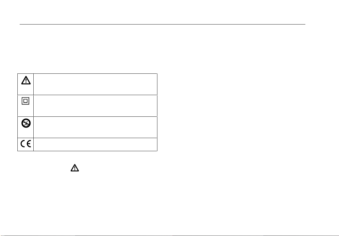
The international electrical symbols used on the
instrument or in this manual are described in Table 1.
Table 1. International Electrical Symbols
Warning or Caution: Risk of damage or destruction
to equipment or software. See explanations in the
manual.
Equipment is protected by double insulation or
reinforced insulation to protect the user against
electric shock.
Do not connect this terminal to public
communications networks, such as telephone
systems.
Conforms to relevant European Union Directives.
Warning
To avoid possible fire, electric shock,
personal injury, or damage to the test tool.
• To avoid false test results, replace the
batteries as soon as “LOW BATTERY”
appears in the display.
• Never connect the test tool to any
telephony inputs, systems, or equipment,
including ISDN. Doing so is a
misapplication of this product, which can
result in damage to the instrument and
create a potential shock hazard to the
user.
• Never connect the test tool to active LAN
inputs, systems, or equipment. Doing so
is a misapplication of this product, which
can result in damage to the instrument
and create a potential shock hazard to the
user.
• Always turn on the test tool before
connecting it to a cable. Turning the test
tool on activates the tool’s input
protection circuitry.
• When servicing the test tool, use only
specified replacement parts.
• Do not use the test tool if it is damaged.
Protection may be impaired.
• Do not use the test tool if it is damaged.
Inspect the test tool before use.
2
Page 11
CableMeter
Getting Acquainted
• Never operate portable transmitting
devices during a cable test. Doing so
might cause erroneous test results.
Getting Acquainted
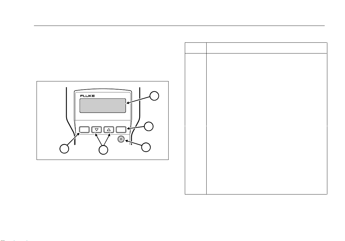
Display, Switches, and Connections
LAN CABLEMETER
620
SETUP
5
Figure 1. Cable Meter System
ENTER
4
Table 2. Features
ITEM FUNCTION
A
1
B
LCD
A 2-line by 16-character LCD display. When there is
more information than can be displayed on two lines,
and up arrow, down arrow, or bidirectional arrow
appears in the left side of the display. Press the
corresponding C or D key to display the
additional information.
E
Enters a selection into the test tool and moves to the
next setup selection. Causes current cable selection to
be displayed and a new measurement cycle initiated
when not in Setup Mode.
2
C
3
B
Turns the display backlight on or off. Backl ighting turns
off automatically after 70 seconds.
D D C
abm01f.eps
E
Scrolls through a selection of choices or multiple
displays
A
Provides access to cable selection, calibration, and
other test tool settings.
3
Page 12

620
Users Manual
Tests the attached cable and indicates
a “pass or fail” based on the
parameters specified for the selected
cable.
Turns the test tool off. See “Battery
Save” feature for more information.
Standard 9-pin (DB9) connector for
connecting IBM shielded twisted
pair (STP) data cable.
OFF
TEST
LENGTH
WIRE MAP
Figure 2. Rotary Switch
Standard 8-pin modular jack for connecting unshielded
(UTP) and foil-screened (FTP) unshielded twisted pair
cable.
STP UTP/FTP COAX
NOT FOR CONNECTION TO PUBLIC TELEPHONE SYSTEMS
Figure 3. Connections
Measures the length of coaxial cables and
each pair of twisted pair cable in feet or
meters and tests for anomalies.
Displays wiring connections, shorts,
opens, and split pairs.
abm02f.eps
BNC connector for connecting coaxial
cables.
abm03f.eps
4
Page 13

CableMeter
Preparing the Test Tool for Use
Audible Signal (Beeper)
The test tool uses an audible tone to signal different
operational conditions. A single short tone indicates a
pass condition withough a Cable ID detected. A two
frequency tone signals a pass condition with a Cable ID
detected. Three short tones signal a test failure. A long
tone sounds whenever an invalid key is pressed. A
continuous, varying-pitch tone signals the test tool is
connected to an active cable and should be disconnected
immediately. To disable the audible signal for the PASS
and FAIL conditions, see “Setup Selection".
Low Battery Indication
When the battery voltage is low bit it is OK to continue,
the test tool displays “LOW BATTERY” once during a
power-on session. When this message first appears there
will be about 8 hours of use left. When the battery voltage
is too low to continue, the unit displays “REPLACE
BATTERY”. To continue using the test tool, you must
replace the batteries. Refer to “Replacing Batteries” .
Battery Save Mode
The test tool turns itself off when there is no switch or key
activity for 10 minutes. To return the test tool to operation,
you must turn the rotary switch to OFF and wait 5
seconds before turning the test tool back on. The Battery
Save feature may be disabled by turning the rotary switch
to OFF, then pressing and holding E while turning the
rotary switch to TEST.
Cable ID Unit
The Cable ID Unit permits the detection of far end wiring
failures and helps identify cables between a room and a
wiring closet. For use with twisted pair cable only.
Selecting the Display Language
The test tool displays messages in English, French,
German, Spanish, and Italian. To change the display
language, perform the following:
1. With the test tool off, press and hold Awhile
turning the rotary switch to TEST.
2. Press C or Duntil the desired languages is
displayed, then press A.
Preparing the Test Tool for Use
Note
The noise filter should be set to the frequency of
the local power mains (50 Hz or 60 Hz). See
“Setup Selections” for this and other customizing
selections.
5
Page 14
620
Users Manual
After connecting the cable under test to the appropriate
connector on top of the test tool, you must select proper
cable type, category, and size before testing or
measuring. It may also be necessary to calibrate the test
tool to the cable under test.
Caution
Having more than one cable connected to the
test tool causes erroneous measurements
Note
If you think the test tool is not performing
properly, refer to “When Something Goes
Wrong”.
Selecting a Cable Type
Characteristics for a variety of LAN cables are designed
into the test too and can be accessed through SETUP.
See Table 3.
Table 3. Predefined Cable List
UTP STP FTP COAX
EIA/TIA 4PR IBM TYPE 1 EIA/TIA 4PR 10BASE2
(Thin)
10BASE-T
2PR
TOKEN RG
2PR
TP-PMD2PR TP-PMD
USOC 4PR RG 59
USOC 3 PR RG-59F
USOC 2PR RG-62
DEC/MMJ
3PR
Note: Refer to Table 11 later in this manual to identify
actual wires tested.
IBM TYPE 6 10BASE-T
2PR
TOKEN RG
2PR
2PR
10BASE5
(Thick)
RG-58
RG-58F
(Foam)
(Foam)
6
Page 15

CableMeter
Preparing the Test Tool for Use
Note
Cables not wired according to the predefined
cable list cause the test tool to detect failures.
However, the test tool will determine the cable’s
length and display the actual cable wiring with
the wire map function. It may be possible to use
the test function by making an adapter that
causes the cable to appear to be properly wired
to the test tool.
To set up the test tool for the desired cable, perform the
following:
Note
The number of steps necessary to select a cable
definition will depend on the type of cable selected.
1. Turn the test tool on by selecting TEST, LENGTH, or
WIRE MAP.
2. Press A.
3. Press C or D until the desired cable type is
displayed, then press E.
4. Press Cor D until the desired wiring standard is
displayed, then press E.
5. Press C or Duntil the desired category is
displayed, then press E.
6. Press C or D until the desired wire size is
displayed.
Note
You can check the cable selection at any time
other than during the setup mode by pressing
the
E
key.
The cable characteristics are now defined by the factory
settings for the cable selected. However, cables coming
from different batches or manufacturers can have
characteristic variances of up to 20 %, causing deviations
in length measurements. To obtain more accurate
measurements, calibrate the test tool to the specific cable
under test.
Calibrating the Test Tool to the Cable
When calibrating the test tool to a specific cable, the
cable should be at least 100 feet (30 m) long and of the
same type and category as the cable under test.
Calibrating with cables longer than 100 feet (30 m) will
improve length measurement accuracy. During the
calibration process, if the cable is found to be defective or
if the cable is less than 50 feet (15 m), “BAD CABLE” is
displayed and the calibration process is terminated.
7
Page 16

620
Users Manual
Caution
For proper calibration, connect the cable
under test directly to the test tool, not
through a patch cable.
abm04f.eps
Caution
To ensure accurate measurements, make
sure conductive objects, including fingers,
do not come in contact with any of the
connectors while the test tool is measuring
the cable under test.
To calibrate the test tool to the currently selected cable,
perform the following:
1. Connect a good cable of known length, 100 feet (30
m) or longer, to the appropriate test tool conenctor
and turn the rotary switch to TEST, LENGTH, or
WIRE MAP.
Note
If you have just completed the cable selection
process, the test tool should already be i the
calibration setup selection.
2. Press A and then E until the following display
appears.
8
Note
When you select a cable type for which the test
tool has already been calibration, “CAL” will
appear in the second line of the display. To
erase this calibration and use the factory
settings, remove all cables from the test tool,
press
press
D D
E.
until “YES” is displayed, and
3. Press C D until YES is displayed, and then
press E. The test tool takes a few measurements
on the attached cable and displays the measured
length.
abm05f.eps
Page 17

CableMeter
Making Tests and Measurements
4. Press C D until the known cable length is
displayed, and then press E. These cable
parameters are stored and will remain in memory
even if the test tool is turned off. All future
measurements for this cable type are compared to
these new parameters until another cable is selected
or another calibration is performed.
Making Tests and Measurements
The test tool displays test results in relation to individual
pin numbers. For example, in the LENGTH mode, the
following display indicates the twisted pari connected to
pins 1 and 2 is 301 feet long whilc the pair connected to
pins 3 and 6 is 300 feet long.
abm06f.eps
When you are testing STP cabling, the pin number
displayed always corresponds to the pins at the STP (DB-
9) connector. Table 4 shows the connections for the
active pins.
Table 4. Active Pin Connections
DB-9 Line Name Data
Connector
Color
1RX+Red4
6 RX- Green 5
5 TX- Black 3
9 TX+ Orange 6
8-Pin RJ45
Note
When you test STP cables, the IBM Data
Connector in the STP Adapter Kit or AMP part
number 555414-2 must be used with the Cable
ID Unit.
Testing Cables
The TEST function teststhe attached cable and indicates
PASS or FAIL based on hte cable’s compliance with the
parameters stored in the test tool for the selected cable.
The tests that are performed (Table 5) depend on
whether or not a Cable ID unit is connected to the far end
of the cable.
9
Page 18

620
Users Manual
Table 5. Twisted Pair Tests
Failures
No Cable ID With Cable ID
Detected
Short X X
Open (near end) X X
Open (far end) X
Length X X
Split Pair X X
Miswire X
Faults X X
To test a cable, do the following:
1. Connect the cable under test to the appropriate
connector on the test tool.
2. Turn the rotary switch to TEST.
3. This step can be omitted if you know the cable
selection is correct for the cable under test. Press
E to check the cable selection. The test tool
displays the cable selection for a few seconds, the
starts the test. “CAL” appears in the second line of
the display if a cable calibration has been performed
for the selected cable type. If the test tool is not set
up for the cable under test, refer to “Preparing the
Test Tool for Use”.
When you are testing twisted pair cables, the test tool
checks for a Cable ID Unit at the other end of the cable
and displays one of the following when a pass condition
exists:
Good cable, Cable ID#8
detected.
abm07f.eps
Good cable, No cable ID
detected.
abm08f.eps
Note
The test tool may not sense the Cable ID Unit
under some open and short conditions. The test
tool will alternately display a ? and a number
when the Cable ID is detected but its number
can not be dertmined with certainty.
10
Page 19

When testing coaxial cables with a termination, the test
tool displays the totatl resistance of the termination and
cable wires.
abm09f.eps
Coaxial cables must be unterminated for the test tool to
display the cable’s length. An open in a coaxial cable
looks just like an unterminated cable. A length
measurement that is less than the known cable length
would indicate a possible open in the cable.
The test tool sounds three short tones and displays FAIL
if a failure is detected. Additional information about the
failure is printed on the second line of the display and if
the ] symbol is displayed, additional information can be
viewed with the D C keys.
Note
The failure messages refer to individual wires
rather than pairs of wires.
CableMeter
Making Tests and Measurements
Failure messages for the TEST mode are described in
Tables 6 and 7.
11
Page 20

620
Users Manual
Failure Display Description
Table 6. Test Failures (without Cable ID Unit)
Short*
(UTP/FTP/STP)
Short*
COAX
Open
Split Pair
SHORT
?
OPEN
OPEN
OPEN
OPEN
Displays shorted wires and the most likely distance
to the short.
abm10f.eps
Displays the most likely distance to the short.
abm11f.eps
Displays open wires and whether the open is at the
near or far end of the cable.
abm12f.eps
Display wire pairings that are incorrect based on
the cable selected.
abm13f.eps
* A short greater than zero ohms causes the test tool to display a legth greater than the actual distance to the
short. See Figure 4. The test tool uses ohms/foot to calculate distance to a short.
12
Page 21

CableMeter
Making Tests and Measurements
80 Feet
LAN CABLEMETER
620
0Ω SHORT
SETUP
ENTER
LENGTH
WIRE MAP
TEST
OFF
70 Feet
LAN CABLEMETER
620
0.5Ω SHORT
SETUP
ENTER
LENGTH
WIRE MAP
TEST
OFF
Figure 4. Testing for Shorts
abm14f.eps
13
Page 22

620
Users Manual
Table 7. Test Failures (with Cable ID Unit)
Failure Display Description
Miswire Displays the incorrect wiring of the end connectors.*
Open Displays the broken wire(s) and the distance to the break.
Pair Length Indicates that the length of the pairs within a cable are
abnormally different. Use LENGTH to check pair lengths.
Split Pair
A portion of the cable assembly has split pairs or a poor quality
cable such as telephone wire was used instead of LAN type
cabling which may cause excessive crosstalk.
Fault
Detects anomalies that do not fit a specific category or failure.**
*Flashes the number of the wires incorrectly connected.
**These non-specific faults are as follows:
• A cable with a resistive path between the wires. Displays measured resistance.
• Shield connected with UTP cable selected.
• UTP cable connected with STP or COAX selected.
14
Page 23

CableMeter
Making Tests and Measurements
Measuring Cable Length
The test tool measures the length of both twisted-pair and
coaxial cables. If the test tool is not calibrated to the cable
under test, then factory default characteristics are sued to
compute hte length. If a more accurate length
measurement is desired, refer to “Calibrating the Test
Tool to the Cable”.
Before a length measurement is made, the test tool
performs diagnostic tests to prevent any cable failures
from corrupting the length measurement. All failures are
described in the “Testing Cables”.
To measure the length of a cable, do the following:
1. Connect the cable under test to the appropriate
connector on the test tool.
2. Turn the rotary switch to LENGTH.
3. This step can be omitted if you know the cable
selection is correct for the cable under test. Press
E to check the cable selection. The test tool
displays the cable selection for a few seconds and
then starts the test. “CAL” appears in the second line
of the display if a cable calibration has been
performed for the selected cable type. If the test tool
is not set up for the cable under test, refere to
“Preparing the Test Tool for Use" to select a new
cable setting.
Note
When the display flashes 999’ (350 m) during a
length measurement, the length of the cable
exceeds the tst tool’s range of measurement.
The information that is displayed depends on the type of
cable selected. For twisted pair cables, each pair has its
corresponding length measurement. A 5 percent
difference in length between pairs is not uncommon.
For EIA/TIA 4PR cable with no failures, the display shows
the following:
abm21f.eps
abm22f.eps
15
Page 24

620
Users Manual
Length of a coaxial cable terminated in a resistance
cannot be determined by the test tool. Only the total
resistance of the wire and termination is displayed. An
unterminated coaxial cable 445 feet long will display the
following:
abm23f.eps
Checking the Wire Map
Using the test tool’s Wire Map function and a Cable ID
Unit, you can determine the wiring of both the near and
far end of the cable. To test the Wire Map, perform the
following:
1. Connect the cable under test to the appropriate
connector on the test tool.
2. Turn the rotary switch to WIRE MAP.
3. This step can be omitted if you know the cable
selection is correct for the cable under test. Press
E to check the cable selection. The test tool
displays the cable selection for a few seconds and
then starts the test. “CAL” appears in the second line
of the display if a cable calibration has been
performed for the selected cable type. If the test tool
is not set up for the cable under test, refere to
“Preparing the Test Tool for Use” to select a new
cable setting.
Note
If you select the COAX wire type while in the
WIRE MAP mode, the test tool will perform the
LENGTH function on the cable.
Assuming the cable attached to the test tool is a EIA/TIA
4 pair cable with no failures, the following display
indicates a good cable:
Near End
Far End
abm24f.eps
The top line always displays the near end of the cable;
the second line always displays the far end.
When the test tool detects a Cable ID Unit but cannot
determine the ID number, #? Is displayed for the ID
number. The test tool will alternately display a ? and a
16
Page 25

CableMeter
Checking the Wire Map
numbe when the Cable ID is detected but the Cable ID
number cannot be detemined with certainty.
Without a Cable ID Unit connected to the far end of the
cable, the test tool displays “—“ for the ID number.
The following display indicates the near end wiring of a
cable without a Cable ID Unit connected.
abm25f.eps
The IBM data connector contains self-shorting
connections between pins 5 and 6 (TX- and RX-) and 1
and 9 )RX+ and TX+) on the STP connector. Since this is
a normal connection for the IBM data connector, the tst
tool does not display a failure. In the wire map function,
the presence of these shorts are displayed as shown
below:
abm26f.eps
Pins connected to wires comprising twisted pairs are
grouped together in the display.
17
Page 26

620
Users Manual
Table 8. Wire Map Failures (using Cable ID Unit)
Failure Display Wiring Description
Short
(near end)
1
2
3
6
1
Alternately displays an "s" with the actual wire number of each wire
2
shorted. Because pins 2 and 3 are shorted, pins 1 and 6 do not
3
appear to be paired.
6
Short
(far end)*
Split Pair
Open
Miswire
* The test tool will alternately display a ? and a number when the Cable ID is detected, but the Cable ID number cannot be determined with certainty.
1
2
3
6
1
2
3
6
1
2
3
6
1
2
3
6
SS
1
2
3
6
Flashes an "s" below the wire number of each wire shorted.
1
2
Because pins 2 and 3 are shorted, pins 1 and 6 do not appear to be
3
paired.*
6
1
Flashes the Wire numbers involved in th e split.
2
3
6
1
Flashes wire pairs that are either poor quality, such as using
2
telephone wire instead of LAN type cabling or a portion of the
3
6
assembly has split pairs which may cause excessive crosstalk.
Alternately displays "o" with the number of each open wire.
1
2
3
6
Displays the wiring detected by the test tool and flashes the wire
1
2
numbers involved in the anomaly.
3
6
18
Page 27

CableMeter
Setup Selections
Setup Selections
The setup mode allows you to select cable characteristics
and customize the test tool’s operation. Once changed,
these settings are stored and remain in the test tool even
when it is turned off. Setup selections that rarely need
changing are under a special “Power-up” menu.
Setup allows you to:
Select cable type (UTP, STP, FTP, or COAX)
Select a wiring standard
Select a cable category
Select a wire size
Calibrate the test too to a specific cable
Enable or display the Beeper for PASS and FAIL
Adjust the display contrast
* Select the display language
* Select length measurement units between feet (‘)
and meters (m)
* Select wire size units between AWG and
millimeters (mm)
* Set the noise filter for 50 Hz or 60 Hz
* “Power-up” setup selections.
To make a SETUP selection, do the following”
1. Press A.
2. Press A to step through the selections.
3. Press C or D to select the desired setup
condition.
4. Press A to exit the setup mode, or press E to
move to the next setup selection.
To make a “Power-up” setup selection, do the follwoing:
1. With the test tool OFF, press and hold A while
turning the rotary switch to TEST.
2. Press E to step through the selections.
3. Press C or D to select the desired setup
condition.
4. Press A to exit the setup mode, or press E to
move to the next setup selection.
19
Page 28

620
Users Manual
Maintenance
General
Periodically wipe the case with a damp cloth and
detergent; do not use abrasives or solvents. Clean and
dry as required. If the test tool will remain unused for an
extended period, remove the batteries to prevent damage
from leakage.
Replacing Batteries
Two 1.5 V AA alkaline batteries power the test tool and
typically provide 50 hours of operation. Using the
backlight may significantly reduce battery life. The battery
compartment is located at the bottom of the test tool. To
remove the battery cover, push the lip in and lift the cover
off (see Figure 5).
When Something Goes Wrong
If it appears that the test tool is not working properly,
perform the checks in Table 9 before returning the test
tool to Fluke for repair. Repairs or servicing not covered
in this manual should be performed only at an authorized
Fluke Service Center.
To contact Fluke, call one of the following telephone
numbers:
USA and Canada: 1-888-99-FLUKE (1-888-993-5853)
Europe: +31 402-678-200
Japan: +81-3-3434-0181
Singapore: +65-738-5655
Anywhere in the world: +1-425-356-5500
Or, visit Fluke’s Web site at www.fluke.com.
+
+
abm42f.eps
Figure 5. Battery Compartment
20
Page 29

Maintenance
Table 9. Basic Troubleshooting
Action Result Explanation
Symptom 1: Display goes blank.
Display is active The Battery Save feature turned the test tool off.*1. Turn the rotary switch to off, wait 5
seconds and turn the switch to TEST.
3. Return the test tool for repair. Problem appears to be a test tool malfunction.
Symptom 2: The test tool doesn’t appear to be measuring correctly.
Proper Operation".
Display still blank Go to step 2.
Display is active Batteries were too low to run the test tool.2. Replace the batteries.
Display still blank Go to step 3.
Self-test fails Internal circuitry is defective. Go to step 3.1. Perform a self-test on the test tool.
Self-test passes Go to step 2.
Verification Fails Test tool defective. Go to step 3.2. Perform the steps under "Verifying
Verification Passes Problem was an operational problem. Check your
procedure and setup.
CableMeter
3. Return the test tool for repair. Problem appears to be a test tool malfunction.
* The Battery Save feature may be disabled by turning the rotary switch to OFF, then press and hold E while turning the
rotary switch to TEST.
21
Page 30

620
Users Manual
Performing a Self-Test
The test tool periodically performs an internal self-test.
When the internal self-test detects a problem, the test tool
displays the following message:
abm43f.eps
A more thorough self-test can be performed by using the
following self-test procedure:
1. With the test tool off, press and hold A while
turning the rotary switch to TEST.
2. Press E until “SELF-TEST?” is displayed.
3. Press C or D to select YES.
Note
To exit without performing a self-test, either
press
A
or ensure that the second line is
displaying “NO” and press
next setup selection.
4. Press E to activate the self-test program.
E
to move to the
You will be prompted to install the Cable ID Unit on
the UTP/FTP connector. (NOT on the end of the
cable.)
5. After installing the Cable ID Unit, press E to
continue the self-test program.
The test tool displays PASS or FAIL. The self-test
continually repeats until A is pressed or the test tool
turns itself off (Battery Save Mode). If any failure is
detected, return the unit to a service center for repair.
Verifying Proper Operation
1. Connect the provided patch cable to the UTP/FTP
connector.
2. Set up the test tool for the patch cable’s type, wiring,
category, and wire size.
3. Connect a Cable ID Unit to the end of the patch
cable.
4. Verify that the Cable ID Unit is properly identified by
the test tool and the cable length is within ±1.0 m (±2
ft) of the patch cable length.
Returning the Test Tool for Repair
If after performing the previous tests you believe the test
tool is not performing properly, you can send it to your
22
Page 31

CableMeter
Maintenance
local service center for repair. Pack the test tool and its
Cable ID Unit in the original shipping container. Forward
Them, postage paid and insured, to the nearest Service
Center. Fluke assumes NO responsibility for damage in
transit.
A 620 LAN CableMeter covered by the limited warranty
will be promptly repaired or replaced (at Fluke’s option)
and returned to you at no charge. See the registration
card for the warranty terms. If the warranty has lapsed,
the test tool will be repaired and returned for a fixed fee.
Contact the nearest Service Center for information and
prices.
Parts and Accessories
Table 10. Parts and Accessories
Description PN
N6201 Cable ID Kit (2 through 4)
N6202 Cable ID Kit (5 through 8)
N5620 Cable Kit:
2 ea. RJ45 Straight through patch cables
2 ea. RJ45 – 8 Clip lead
2 ea. RJ 45 In-line Couplers
1 ea. 50 ohm BNC Coaxial Patch Cable
N6203 STP Cable Kit:
1 ea. IBM Type 1 Adapter cable
(DB9 to Data Connector)
1 ea. RJ45 to IBM Data Connector
Adapter
946801
946806
935957
946970
23
Page 32

620
Users Manual
Table 10. Parts and Accessories (cont)
Description PN
Users Manual 938386
Main PCA 936570
LCD Module, 32 Character 949107
Cable Identifier #1 946830
Cable Identifier #2 946835
Cable Identifier #3 946843
Cable Identifier #4 946855
Cable Identifier #5 946897
Cable Identifier #6 946921
Cable Identifier #7 942926
Cable Identifier #8 946934
Case, Top 949102
Case, Bottom 938449
Battery Door 938451
620 Shaft extender 938456
Knob 880815
Softcase 454389
Lens 946868
Battery, AA, Alkaline 376756
RJ45 Straight through patch cable 927868
RJ45 – 8 Clip Lead 938394
RJ45 In-Line Coupler 927884
BNC Coaxial Patch Cable 927876
Type 1 Adapter Cable (DB9 to Data Conn) 928499
RJ45 to IBM Data Connector Adapter 929435
Specifications
Assumes test tool was calibrated using 100 foot (or
longer) cable of the type and batch of the cable being
measured. Accuracy is specified for a period of two years
after calibration.
Cable Length Measurements
Range : 1.0 to 350 m (2 ft to 999 ft)
Accuracy: 5 % +0.5 m (7 % + 2 ft)
Resolution:
Measurement Units in Feet: 1 ft
Measurement Units in Meters
Cables < 100 meters: 0.5 m
Cables > 100 meters: 1 m
24
Page 33

CableMeter
Specifications
Failures Detected
Shorts
Range of short detection: 0 m to 350 m (1 ft to 999 ft)
Accuracy of distance to a short (Assumes short is 0 Ω):
UTP/FTP/STP: 7 % + 3 m (7 % + 10 ft)
Coaxial Cables 10 % + 10 m (10 % + 30 ft)
Resolution of distance to a short:
UTP/FTP/STP: 0.5 m (1 ft)
Coaxial Cables: 1 m (5 ft)
Opens
Range of open detection: 0 m to 350 m ( 0 ft to 99 ft)
Accuracy of distance to an open:
UTP/FTP/FTP: 10 % + 1 m (10 % + 3 ft)
Resolution of distance to an open:
Cables < 100 meters: 0.5 m (1 ft)
Cables > 100 meters: 1 m (3 ft)
Split Pairs
Split pair part of the cable must be at least 2 meters (6 ft)
in length and greater than 10 % of the total cable length.
Coax Termination Measurements
Any loop resistance value between 5 ohms and 350
ohms is interpreted as a termination resistance.
Resistance values below 5 ohms are considered shorts
and resistance values greater than 350 ohms are not
displayed.
LAN Input Connectors
RJ45, DB-9, and BNC
Input Protection
56 V dc continuously through a balanced source
impedance of 400 Ω. 175 V peak, 20 Hz to 60 Hz through
100 Ω, superimposed on 56 V dc through 400 Ω.
“ACTIVE CABLE” is displayed and an audible signal
sounds when the test tool is connected to a cable with
voltage present.
The test too is not intended to be connected to a public
telephone network.
Range of detection: 2 m to 350 m (6 ft to 999 ft)
25
Page 34

620
Users Manual
Table 11. Cable Test Characteristics
Cable Wiring PASS/FAIL Pins
UTP/FTP*
(RJ45)
STP*
(DB-9)
* Tests for open or shorted Shield on FTP and STP
cables.
** RJ25 PINS
***RJ11 PINS
EIA/TIA 4 PR
10BASE-T 2 PR
TOKEN RING 2 PR
TP-PMD 2 PR
USOC 4 PR
USOC 3 PR
USOC 2 PR
DEC/MMJ 3 PR
IBM Type 1
IBM Type 6
Pins 12 36 45 78
Pins 12 36
Pins 36 45
Pins 12 78
Pins 18 27 36 45
Pins 16 25 34**
Pins 25 34***
Pins 16 23 45**
Pins 15 69
Pins 15 69
26
Page 35

Table 12. Coax Cable Characteristics
CableMeter
Specifications
620 Coax Setup Impedance Resistance
(Center Conductor + Shield)
10 BASE2 50Ω 14.6Ω/1000 ft
47.9Ω/km
10BASE5 50Ω 2.94Ω/1000 ft
9.66Ω/km
RF58 50Ω 14.9Ω/1000 ft
48.8Ω/km
RG-58F 50Ω 12.9Ω/1000 ft
42.3Ω/km
RG-59 75Ω 49.6Ω/1000 ft
160.9Ω/km
RG-59F 75Ω 17.6Ω/1000 ft
57.7Ω/km
RG-62 93Ω 44.1Ω/1000 ft
144.6Ω/km
Capacitance Example
25.4 pF/ft
83.3 pF/m
26.0 pF/ft
85 pF/m
30.8 pF/ft
101 pF/m
26.0 pF/ft
85.3 pF/m
20.5 pF/ft
67.2 pF/m
17.3 pF/ft
56.8 pF/m
13.5 pF/ft
44.3 pF/m
Trade No. 9907
Trade No. 9880
Trade No. 9203
RF-58/U
Trade No. 8219
Trade No. 9204
RG-59/U
Trade No. 9259
Trad No. 9862
RG-62-U
27
Page 36

620
Users Manual
Power
Two AA size 1.5 V alkaline batteries
Battery Type: ANSI/NEDA-15A or IEC-LR6
Low Battery indicated in the display
Typical Battery Life: 50 hours
Timed Power-Off Function
Dimensions
18.4 cm x 9.8 cm x 4.6 cm
(7.25 in x 3.875 in x 1.8 in)
Weight
354.4 g (12.5 oz)
Environmental Conditions
Temperature:
Non Operating (storage): -20 °C to +60 °C
Operating: 0 °C to +45 °C
Operating Humidity:
10 °C to 30 °C: 95 % ±5 % RH (without condensation)
30 °C to 40 °C: 75 % ±5 % RH (without condensation)
40 °C to 45 °C: 45 % ±5 % RH (without condensation)
Altitude:
Non Operating: 0 km to 12 km (40,000 ft)
Operating: 0 km to 4.57 km (15,000 ft)
Electromagnetic Compatibility:
Meets FCC part 15-b
Meets EN 50081-1
Meets EN 50082-1
Meets vfg 243/1991
Display
2 lines of 16 characters LCD with backlight.
Controls
Four position rotary switch plus 5 tactile-feedback
momentary switches.
Warranty
One year from date of purchase
Calibration Period
Two years
28
 Loading...