

Page 1

DataSim 6100
Patient Simulator
Operators Manual
PN 2242959
February 2008
© 2008 Fluke Corporation, All rights reserved. Printed in USA. Specifications subject to change without notice.
All product names are trademarks of their respective companies.
Page 2

Warranty and Product Support
Fluke Biomedical warrants this instrument against defects in materials and
workmanship for one year from the date of original purchase. During the warranty period, we will repair or at our option replace, at no charge, a product
that proves to be defective, provided you return the product, shipping prepaid,
to Fluke Biomedical. This warranty covers the original purchaser only and is
not transferable. The warranty does not apply if the product has been damaged
by accident or misuse or has been serviced or modified by anyone other than
an authorized Fluke Biomedical service facility. NO OTHER WARRANTIES,
SUCH AS FITNESS FOR A PARTICULAR PURPOSE, ARE EXPRESSED
OR IMPLIED. FLUKE SHALL NOT BE LIABLE FOR ANY SPECIAL, INDIRECT, INCIDENTAL OR CONSEQUENTIAL DAMAGES OR LOSSES,
INCLUDING LOSS OF DATA, ARISING FROM ANY CAUSE OR THEORY.
This warranty covers only serialized products and their accessory items that
bear a distinct serial number tag. Recalibration of instruments is not covered
under the warranty
This warranty gives you specific legal rights and you may also have other
rights that vary in different jurisdictions. Since some jurisdictions do not allow
the exclusion or limitation of an implied warranty or of incidental or consequential damages, this limitation of liability may not apply to you. If any provision of this warranty is held invalid or unenforceable by a court or other decision-maker of competent jurisdiction, such holding will not affect the validity
or enforceability of any other provision.
07/07
Page 3

Notices
All Rights Reserved
© Copyright 2008, Fluke Biomedical. No part of this publication may be reproduced, transmitted, transcribed, stored in a retrieval system, or translated into any language without the written
permission of Fluke Biomedical.
Copyright Release
Fluke Biomedical agrees to a limited copyright release that allows you to reproduce manuals and
other printed materials for use in service training programs and other technical publications. If
you would like other reproductions or distributions, submit a written request to Fluke Biomedical.
Unpacking and Inspection
Follow standard receiving practices upon receipt of the instrument. Check the shipping carton for
damage. If damage is found, stop unpacking the instrument. Notify the carrier and ask for an
agent to be present while the instrument is unpacked. There are no special unpacking instructions,
but be careful not to damage the instrument when unpacking it. Inspect the instrument for physical damage such as bent or broken parts, dents, or scratches.
Technical Support
For application support or answers to technical questions, either email
techservices@flukebiomedical.com
1-425-446-6945.
Claims
Our routine method of shipment is via common carrier, FOB origin. Upon delivery, if physical
damage is found, retain all packing materials in their original condition and contact the carrier
immediately to file a claim. If the instrument is delivered in good physical condition but does not
operate within specifications, or if there are any other problems not caused by shipping damage,
please contact Fluke Biomedical or your local sales representative.
or call 1-800- 648-7952 or
Standard Terms and Conditions
Refunds and Credits
Please note that only serialized products and their accessory items (i.e., products and
items bearing a distinct serial number tag) are eligible for partial refund and/or credit.
Nonserialized parts and accessory items (e.g., cables, carrying cases, auxiliary modules,
etc.) are not eligible for return or refund. Only products returned within 90 days from the date
of original purchase are eligible for refund/credit. In order to receive a partial refund/credit of a
product purchase price on a serialized product, the product must not have been damaged by the
customer or by the carrier chosen by the customer to return the goods, and the product must be
returned complete (meaning with all manuals, cables, accessories, etc.) and in “as new” and resalable condition. Products not returned within 90 days of purchase, or products which are not in
“as new” and resalable condition, are not eligible for credit return and will be returned to the customer. The Return Procedure (see below) must be followed to assure prompt refund/credit.
Restocking Charges
Products returned within 30 days of original purchase are subject to a minimum restocking fee of
15 %. Products returned in excess of 30 days after purchase, but prior to 90 days, are subject to a
minimum restocking fee of 20 %. Additional charges for damage and/or missing parts and accessories will be applied to all returns.
Page 4

Return Procedure
All items being returned (including all warranty-claim shipments) must be sent freight-prepaid to
our factory location. When you return an instrument to Fluke Biomedical, we recommend using
United Parcel Service, Federal Express, or Air Parcel Post. We also recommend that you insure
your shipment for its actual replacement cost. Fluke Biomedical will not be responsible for lost
shipments or instruments that are received in damaged condition due to improper packaging or
handling.
Use the original carton and packaging material for shipment. If they are not available, we recommend the following guide for repackaging:
Use a double-walled carton of sufficient strength for the weight being shipped.
Use heavy paper or cardboard to protect all instrument surfaces. Use nonabrasive
material around all projecting parts.
Use at least four inches of tightly packed, industry-approved, shock-absorbent
Returns for partial refund/credit:
Every product returned for refund/credit must be accompanied by a Return Material Authorization (RMA) number, obtained from our Order Entry Group at 1-800-648-7952 or 1-425-446-
6945.
Repair and calibration:
To find the nearest service center, go to www.flukebiomedical.com/service
In the U.S.A.:
Cleveland Calibration Lab
Tel: 1-800-850-4606
Email: globalcal@flukebiomedical.com
Everett Calibration Lab
Tel: 1-888-993-5853
Email: service.status@fluke.com
In Europe, Middle East, and Africa:
Eindhoven Calibration Lab
Tel: +31-402-675300
Email: ServiceDesk@fluke.com
In Asia:
Everett Calibration Lab
Tel: +425-446-6945
Email: service.international@fluke.com
material around the instrument.
, or
Certification
This instrument was thoroughly tested and inspected. It was found to meet Fluke Biomedical’s
manufacturing specifications when it was shipped from the factory. Calibration measurements
are traceable to the National Institute of Standards and Technology (NIST). Devices for which
there are no NIST calibration standards are measured against in-house performance standards using accepted test procedures.
WARNING
Unauthorized user modifications or application beyond the published specifications may
result in electrical shock hazards or improper operation. Fluke Biomedical will not be responsible for any injuries sustained due to unauthorized equipment modifications.
Page 5

Restrictions and Liabilities
Information in this document is subject to change and does not represent a commitment
by Fluke Biomedical. Changes made to the information in this document will be incorporated in new editions of the publication. No responsibility is assumed by Fluke Biomedical for the use or reliability of software or equipment that is not supplied by Fluke Biomedical, or by its affiliated dealers.
Manufacturing Location
The DataSim 6100 Patient Simulator is manufactured in Everett, Washington by Fluke
Biomedical, 6920 Seaway Blvd., Everett, WA, U.S.A.
Page 6

Page 7

Table of Contents
Chapter Title Page
1 Introduction and Specifications.............................................. 1-1
Introduction .......................................................................................... 1-3
Features................................................................................................. 1-3
General Safety Considerations.............................................................. 1-4
Symbols ............................................................................................ 1-4
Warnings and Cautions..................................................................... 1-4
Instrument Familiarity .......................................................................... 1-5
Front Panel........................................................................................ 1-5
Pendant Keypad Controller............................................................... 1-9
Direct Functions............................................................................ 1-10
Special Functions.......................................................................... 1-10
PAC and PVC Insertion ................................................................ 1-17
Modifier/Cal Mode ....................................................................... 1-18
Specifications........................................................................................ 1-19
Accessories ........................................................................................... 1-21
2 Operation .................................................................................. 2-1
Introduction .......................................................................................... 2-3
Size Adjustments .................................................................................. 2-3
Calibration ............................................................................................ 2-5
Heart Rate Adjustment.......................................................................... 2-6
Artifact Simulation ............................................................................... 2-7
Respiration............................................................................................ 2-8
Defibrillation Training.......................................................................... 2-9
Blood Pressure Simulation.................................................................... 2-11
Personality Modules (Optional Special Functions)............................... 2-12
Interactive IABP Personality Modules.............................................. 2-16
Cardiac Output Personality Modules ................................................ 2-18
Blood Pressure Cables .......................................................................... 2-19
Connector Interface Pin Definitions...................................................... 2-21
3 Maintenance, Service, and Calibration................................... 3-1
Maintenance.......................................................................................... 3-3
Avoiding Damage............................................................................. 3-3
Cleaning............................................................................................ 3-3
i
Page 8

DataSim 6100
Operators Manual
Battery Charging and Replacement...................................................... 3-4
Service and Calibration ........................................................................ 3-5
ii
Page 9

List of Tables
Table Title Page
1-1. Symbols.............................................................................................. 1-4
1-2. Simulator Front Panel Controls and Indicators .................................. 1-7
1-3. Lead ECG Amplitude......................................................................... 1-8
1-4. Pendant Keypad Controls and Indicators ........................................... 1-10
1-5. Pendant Keypad Codes and Functions ............................................... 1-11
1-6. Functions Used in the Modifier/Cal Mode......................................... 1-18
1-7. Standard Accessories ......................................................................... 1-21
1-8. Optional Accessories (Series 90) Blood Pressure Cables................... 1-22
2-1. Waveform Amplitudes ....................................................................... 2-3
2-2. Effects of Size Adjustments on Parameters........................................ 2-4
2-3. Calibration Functions ......................................................................... 2-6
2-4. Heart Rates Obtained via Rate Adjust Special Function .................... 2-7
2-5. Artifact Modifier Effects.................................................................... 2-8
2-6. Personality Modules........................................................................... 2-13
2-7. Appropriate Pressure Simulator Interface Cables............................... 2-19
2-8. ECG Connectors ................................................................................ 2-21
2-9. Pressure Connectors ........................................................................... 2-22
iii
Page 10

DataSim 6100
Operators Manual
iv
Page 11

List of Figures
Figure Title Page
1-1. Simulator Front Panel Controls and Indicators .................................. 1-6
1-2. Pendant Keypad Controls and Indicators ........................................... 1-9
2-1. Pressure Cable Wiring for Monitor with 5 µV/V mmHg Sensitivity . 2-20
2-2. Pressure Cable Wiring for Monitor with 40 µV/V mmHg Sensitivity 2-21
2-3. Connector Pin Assignments ............................................................... 2-22
v
Page 12

DataSim 6100
Operators Manual
vi
Page 13

Chapter 1
Introduction and Specifications
Contents Page
Introduction ................................................................................. 1-3
Features........................................................................................ 1-3
General Safety Considerations..................................................... 1-4
Symbols.................................................................................... 1-4
Warnings and Cautions ............................................................ 1-4
Instrument Familiarity ................................................................. 1-5
Front Panel ............................................................................... 1-5
Pendant Keypad Controller ...................................................... 1-9
Direct Functions ................................................................... 1-10
Special Functions.................................................................. 1-10
PAC and PVC Insertion........................................................ 1-17
Modifier/Cal Mode............................................................... 1-18
Specifications............................................................................... 1-19
Accessories .................................................................................. 1-21
1-1
Page 14

DataSim 6100
Operators Manual
1-2
Page 15

Introduction and Specifications
Introduction
1
Introduction
The DataSim 6100 Patient Simulator, hereafter referred to as the Simulator, is
a battery-operated, six-channel patient simulator and defibrillation trainer.
Critical care nurses, ACLS program instructors, and other clinical educators
can generate an extensive range of simulations, from a simple normal sinus
rhythm to a complex Swan-Ganz catheter insertion, as well as a wide range of
real world ECG, pressure, and respiration artifacts. In the standard
defibrillation training mode, the instructor can interface the Simulator with
patient manikins and teach students the correct way to defibrillate a patient,
plus the desired effect on ECG and BP activity.
All control keys and display prompts are on a hand-held pendant keypad
connected to the unit with a flexible, 20-foot, coiled telephone-style cord that
gives a wide range of motion. Standard waveforms and sequences, selected via
the keypad, are stored in microcomputer memory within the Simulator.
A variety of optional Personality Modules expands the number of available
waveform selections and sequences and includes functions for special purpose
ECG, Cardiac Output Dilution Curves, Capnography, and IABP. Each
personality module plugs into the Simulator front panel.
A video adapter allows display of generated ECG and BP waveforms on any
standard TV set. The enlarged format increases visibility and comfort level for
a class of students.
Features
The Simulator has the following features:
• Training capabilities
• Six channels for generating ECG, arrhythmias, blood pressure, and
respiration
• Synchronization of hemodynamic waveforms
• Manual PAC and PVC insertions
• Swan-Ganz procedure
• Interface with Resusci-Anne, Arrhythmia Anne, and Chris Clean manikins
• Optional Personality Modules
• Video adapter interface
1-3
Page 16

DataSim 6100
Operators Manual
General Safety Considerations
Read the Users Manual before operating the Analyzer.
Note
If calibration or other service of the Simulator is required, only
qualified service personnel should be permitted to remove the front
panel of the Simulator.
Symbols
Table 1-1 describes the symbols associated with the Analyzer.
Table 1-1. Symbols
Symbol Description
X Hazardous voltage
W Important information; refer to manual.
P Conforms to European Union directives
~
Do not dispose of this product as unsorted municipal waste. Go
to Fluke’s website for recycling information.
Warnings and Cautions
A Warning identifies hazardous conditions and actions that could cause
bodily harm or death.
A Caution identifies conditions and actions that could damage the Analyzer,
the equipment under test, or cause permanent loss of data.
Levels of signals available via the output connectors and the Personality
Module connector do not exceed 12 volts, and as such, do not constitute a
potential danger to the operator. However, observe the following:
1-4
Page 17

Introduction and Specifications
Instrument Familiarity
XW Warning
To avoid possible electrical shock or personal injury,
follow these guidelines:
• Use this Simulator only in the manner specified by the
manufacturer or the protection provided may be impaired.
• Read the Users Manual before operating the Simulator .
• Do not connect the Simulator to a patient or equipment
connected to a patient. The Simulator is intended for
equipment evaluation only and should never be used in
diagnostics, treatment or in any other capacity where the
Simulator would come in contact with a patient
1
Instrument Familiarity
The functions of the Simulator are controlled from the front panel and the
pendant keypad.
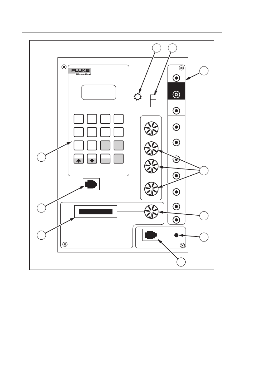
Front Panel
Figure 1-1 shows the front panel controls and indicators of the Simulator.
Table 1-2 lists these components with accompanying descriptions.
1-5
Page 18
DataSim 6100
Operators Manual
1 2
10
DataSim 6100
Patient Simulator
NSR1TACH2BRAD3ASYS
0
A-FLTR5A-FIB62AVB172AVB2
4
3AVB9PAC
V-TAC
PVC1 PVC2
SPEC
V-FIB
STD
FUNC
8
CPLT
KEYPAD
POWER
ECG
ART
PA
RA
On
Off
LL (+)
LA (-)
RA
RL
V1
V2
V3
V4
V5
(-)
3
4
9
AUX
V6
PERSONALITY
8
MODULE
MANKIN
SIMULATE
DEFIB
5
6
1-6
7
Figure 1-1. Simulator Front Panel Controls and Indicators
fdg001.eps
Page 19

Introduction and Specifications
Instrument Familiarity
Table 1-2. Simulator Front Panel Controls and Indicators
Label Component Description
1
A Power Indicator Illuminates when power is ON
B Power Switch Switches power on and off
This battery operated unit is
rechargeable with the supplied charger.
C ECG Snap
Connectors
D Pressure Output
Connectors
Outputs low level 12 lead ECG
Attach standard patient ECG cable lead
wires to these snap connectors to
display the simulated ECG waveforms
on the monitor screen.
To minimize 60-cycle artifact, use a
reference electrode connection. For
example, most five-lead ECG diagnostic
recorders require that a Simulator REF
signal is connected to the RL input of
the patient cable. The Simulator can
also output the ECG in a modified chest
lead configuration (MCL2) used for
bedside monitoring. Simply attach the
LL (+) red, RA (-) white, and LA (ref)
patient cable snaps to the patient
Simulator. Refer to the operators
manual of the ECG monitor for hook-up
instructions.
Output for arterial, PA, and RA
pressures
This output simulates the electrical
output of the BP transducer that would
be used with the patient monitor. The
Simulator generates signals that are
compatible with either 5 or 40-microvolt
transducers.
1-7
Page 20

DataSim 6100
Operators Manual
Table 1-2. Simulator Front Panel Controls and Indicators (cont.)
Label Component Description
E Aux Input/Output
Connector
Cable interconnects for optional
waveform, such as capnography and
IABP
F Manual Defib Switch Manually simulates defibrillation
G Defib Connector Input for Arrhythmia Anne or Chris
Clean manikins equipped with
defibrillation option
H Personality Module
Connector
Input for optional modules
Used to add numerous functions and
waveforms to the standard set
I Keypad Connector Input for hand-help keypad
J Keypad Rest Storage area for the keypad
Inner
Well
Back Battery Charger
Input Connector
Table 1-3. Lead ECG Amplitude
Lead # ECG Amplitude
I +.25 mv (+/- 5%)
II +1.0
III +.75
AVR .60
AVL -.25
AVF +.90
V1 .40
V2 .90
V3 +.60
V4 +1.0
V5 +1.5
V6 + 1.0
Jack used to recharge battery
The unit can be operated while
recharging.
1-8
Page 21

Introduction and Specifications
Instrument Familiarity
1
Pendant Keypad Controller
The pendant keypad controller has two general classes of functions, direct and
special, that are accessed by pressing individual keys or combinations of keys.
The following pages describe functions and codes available in the standard
Simulator unit. Figure 1-2 shows the keypad controls and indicators, and Table
1-4 lists and describes these components.
DataSim 6100
Patient Simulator
1
NSR1TACH2BRAD3ASYS
0
A-FLTR5A-FIB62AVB172AVB2
4
3AVB9PAC
V-TAC
PVC1 PVC2
SPEC
V-FIB
STD
FUNC
8
CPLT
5
2
4
3
Figure 1-2. Pendant Keypad Controls and Indicators
fdg002.eps
1-9
Page 22

DataSim 6100
Operators Manual
Table 1-4. Pendant Keypad Controls and Indicators
Label Element Description
A LCD Display
Screen
B Direct
Function Keys
C Special
Function Key
D Palpitation
Keys
E Mode/Cal
Keys
Eight-character display shows prompts, messages,
confirmations, results
Fifteen of the 16 keys; excluding the SPEC FUNC key
Key at the lower right corner (fourth row) of the
keypad; labeled SPEC FUNC
The second, third, and fourth keys in the third row of
the keypad; labeled PAC, PVC1, and PVC2
Allow user to add a palpitation to any other selected
rhythm
Dual function; the first, second, and third keys in the
fourth row of the keypad; labeled CPLT/] , V-TAC/[ ,
and V-FIB/STD
Allow user to select a mode or, when used with
Special Functions, to adjust the value of the selected
parameter
Direct Functions
To perform Direct Functions, the user selects the desired rhythm by pressing
one of the 15 direct function keys (0-9, PVC1, PVC2, CPLT, V-TAC, and V-
FIB). For example, to initiate a bradycardia rhythm, the user presses and
releases the 2 key that is labeled BRAD. The Simulator automatically
determines the proper time in the cardiac cycle to begin a new rhythm.
Special Functions
To perform Special Functions, the user presses and releases the SPEC FUNC
key, followed by the appropriate two-digit code, found in the printed
menus attached to either side of the keypad. The Simulator displays the *
symbol in response to the SPEC FUNC key selection. The two-digit function
code must be entered when the * prompt is displayed. For example, to select a
bigeminy rhythm, the user presses the SPEC FUNC key followed by the code
1-10
Page 23

Introduction and Specifications
Instrument Familiarity
1
27. Functions can be selected in any order to simulate virtually any patient
condition sequence.
After the code is input, the following prompt displays:
], [ or STD
At this prompt, the user can adjust the value of the parameter as desired:
• ] - Increases parameter value; momentarily displays at max“ when
maximum value is reached
• [ - Decreases parameter value; momentarily displays at min when
minimum value is reached
• STD - Resets parameter value to the standard value
Some of the Special Functions are actually programmed sequences of rhythms
or events. Table 1-5 describes the codes and functions.
Table 1-5. Pendant Keypad Codes and Functions
Code Function Description
00 NORMAL SINUS Provides a convenient way to return to
normal sinus rhythm at a rate of 70 BPM
01 SINUS
TACHYCARDIA
02 SINUS
BRADYCARDIA
03 ASYSTOLE No beats but very small irregular signal
04 ATRIAL
FLUTTER
05 ATRIAL
FIBRILLATION
06 2nd DEGREE AV
BLOCK I
Rapid regular rhythm with normal P
wave and heart rate of 140 BPM
Slow regular rhythm with normal P wave
and heart rate of 35 BPM
remains
Regular ventricular rhythm; atrial flutter
with 4:1 conduction
Rapid irregular atrial signal with no real
P waves; irregular ventricular rate
Wenckebach; irregular rhythm with
normal P waves; PR interval lengthens
progressively until a dropped beat
occurs and cycle repeats.
1-11
Page 24

DataSim 6100
Operators Manual
Table 1-5. Pendant Keypad Codes and Functions (cont.)
Code Function Description
07 2nd DEGREE AV
BLOCK II
08 3rd DEGREE AV
BLOCK
09 PAC INSERT Premature atrial contraction; a single
10 PVC1 INSERT Premature ventricular contraction; a
11 PVC2 INSERT Premature ventricular contraction; a
12
13 VENTRICULAR
14 VENTRICULAR
15 ATRIAL
16 ATRIAL
17 FREQUENT
18 PEDIATRIC
19 1st DEGREE AV
COUPLET Irregular rhythms with frequent couplets
TACHYCARDIA
FIBRILLATION
TACHYCARDIA
TACHYCARDIA/
ABERRANCY
PACs
TACHYCARDIA
BLOCK
Slow regular rhythm with normal P
wave; PR interval in conduced beats is
normal; 3:1 block
Slow regular ventricular rhythm; regular
atrial rhythm; independent atrial and
ventricular rhythms
PAC is inserted into the current rhythm.
Single PVC1 is inserted into the current.
single PVC2 is inserted into the current.
and 1 pair of ventricular beats; PVCs are
premature; compensatory pause follows
couplet.
Irregular, rapid rhythm with irregular,
successive PVCs; no P waves
Irregular, rapid, chaotic waveforms with
no QRS
ATRIAL
Rapid, regular rhythm with biphasic P
Rapid, regular rhythms with biphasic P
wave and notched wide QRS.
Irregular rhythm with frequent premature
PACs and a biphasic P wave
Rapid regular rhythm with tall R wave
and narrow QRS
BLOCKS
Normal beats except with long PR
interval of .25 sec
1-12
Page 25

Introduction and Specifications
Instrument Familiarity
Table 1-5. Pendant Keypad Codes and Functions (cont.)
Code Function Description
1
20 BUNDLE
BRANCH BLOCK
22 ACCELERATED
JUNCTIONAL
23 JUNCTIONAL Slow regular rhythm with inverted P
24 FREQUENT PJCs Irregular rhythm with frequent,
26 IDIOVENTRICULAR Slow regular rhythm, no P waves,
27 BIGEMINY Irregular rhythm alternates between
28 UNIFOCAL PVCs Frequent, premature unifocal PVCs
29 MULTIFOCAL
PVCs
30 TRIPLET Frequent runs of 3 consecutive PVCs
31 VENTRICULAR Pacer artifact precedes QRS. Regular
32 ATRIAL Normal rhythm, pacer artifact precedes
33 AV SEQUENTIAL Prolonged PR interval; pacemaker
Wide QRS complexes; regular rhythm
with a PR interval of .16 sec
JUNCTIONAL
Regular rhythm with inverted P wave
and short PR interval
wave and short PR interval
premature PJCs, followed by a pause;
inverted P wave and short PR interval
VENTRICULAR
wide QRS
PVC and normal beat.
followed by pause; PVC has wide
QRS.
Regular rhythms with frequent PVCs
that alternate between type 1 and type
2; pause follows PVCs
PACEMAKER
rhythm, no P waves, wide QRS
P wave.
artifact precedes P and QRS waves.
Wide QRS.
1-13
Page 26

DataSim 6100
Operators Manual
Table 1-5. Pendant Keypad Codes and Functions (cont.)
Code Function Description
34 SENSE and
CAPTURE FAIL
35 FAILURE TO
CAPTURE
38 CARDIAC
FAILURE
39 ST ELEVATION Regular rhythm with ST Elevation at 2
40 ST DEPRESSION Regular rhythm with ST Depression at 3
41 AGONAL No P waves; wide complexes with
42 VENTRICULAR
ASYSTOLE
43 CONVERSION Vfib with CPR followed by Vfib without
46 DEFIBRILLATION Positive and negative baseline
47 60 CYCLE
ARTIFACT
48 ECG/RESP
ARTIFACT
Frequent loss of capture, low amplitude
escape beat, sensing failure of escape
beat
No capture; pacer artifact amplitude is 8
mV with 1 msec duration.
MISC ECG
Intermittent PVCs and couplet followed
by ventricular tachycardia, followed by
ventricular fibrillation, followed by
asystole
mm 80 msec after J point
mm 80 msec after J point
periods of asystole
No QRS, regular atrial rhythm
CPR for 2 seconds prior to defib: Defib
artifact, Brady rhythm with CPR, Brady
rhythm without CPR, followed by NSR
ECG ARTIFACT
saturation; artifact is automatically
followed by pre-selected rhythm (see
#59 below).
Artifact amplitudes 0.1, 0.4, and 0.7 mV
p-p; use ] and [ keys or eliminate with
STD key.
Artifact amplitudes 0.4, 0.6 and 1.0 mV
peak to peak; use ] and [ keys or
eliminate with STD key.
1-14
Page 27

Introduction and Specifications
Instrument Familiarity
Table 1-5. Pendant Keypad Codes and Functions (cont.)
Code Function Description
1
49 MUSCLE
ARTIFACT
50 CPR CPR artifact a 70/min
53 ECG RATE
ADJUST
54 SIZE ADJUST Increases and decreases ECG, BP, and
55 AUTO TREND Automatically varies NSR heart and
DEFIB CONVERSATION
59 RHYTHM
SELECT
60 DEFIB DISABLE Disables auto defib sequence
71 APNEA Thoracic impedance is simulated via
72 RESP AT 10 BPM Respiration waveform at 10 BPM
73 RESP AT 20 BPM Respiration waveform at 20 BPM
74 RESP AT 40 BPM Respiration waveform at 40 BPM
75 RESP AT 80 BPM Respiration waveform at 80 BPM
76 CVA
COINCIDENCE
Artifact amplitudes 0.4, 0.6 and 1.0 mV
peak to peak; use ] and [ keys or
eliminate with STD key.
ADJUST
Increases or decreases rate in 10%
increments; STD returns to standard
rate.
respiration waveforms or returns them to
standard size; use after selecting
desired channel.
respiration rates and blood pressures;
Vtach episode 4 every 1 hour; trend
repeats every 2 hours.
Permits selection of post defib rhythm,
which is then automatically inserted after
defib artifact.
RESPIRATION
ECG output snaps.
ECG and respiration are synchronized
and timed appropriately for
cardiovascular artifact. Impedance drops
immediately after each R wave.
1-15
Page 28

DataSim 6100
Operators Manual
Table 1-5. Pendant Keypad Codes and Functions (cont.)
Code Function Description
77 PEDIATRIC
APNEA/BRADY
78 HEART RATE
CALIBRATION
81 LINEARITY/SPEED 2.5 Hz triangular ECG waveform
82 ECG SIZE
CALIBRATION
83 ARRHYTHMIA
SEQUENCE
84 RESPIRATION
SIZE CAL
BLOOD PRESSURE
62 ZERO
PRESSURE
63 PATENT LINE Outputs a 50 mmHg flush waveform on
64 RESONANT LINE Outputs a 50 mmHg flush waveform on
Intermittent apnea periods; heart rate
drops from 140 BPM to 70 BPM each
apnea period.
CALIBRATION
Calibrated heart rates from 30 to 300
BPM
Cal pulse amplitudes from .25 mV to
2.5 mV
Automatic sequence of arrhythmias
over 3 minute period of time: NSR,
Dropped Beat, AV Pace, V Pace,
Atrial Tach, Couplet, RBBB, Triplet,
Bigeminy (3 Foci), Vtach
Respiratory depth ranging from 0.25 to
2.5 ohm; calibrated for RA-LA lead
Zeros all three-pressure channels as
well as auxiliary CO2 channel
PA channel
PA waveform follows flush. Trailing edge
of flush and PA pressure waveforms
demonstrate ideal frequency
characteristics of pressure line.
PA channel
PA waveform follows flush. Trailing edge
of flush and PA pressure waveforms
demonstrate resonant frequency
characteristics of pressure line.
1-16
Page 29

Introduction and Specifications
Instrument Familiarity
Table 1-5. Pendant Keypad Codes and Functions (cont.)
Code Function Description
65 DAMPED LINE Outputs a 50 mmHg flush waveform on
PA channel.
PA waveform follows flush. Trailing edge
of flush and PA pressure waveforms
demonstrate damped frequency
characteristics of pressure line.
66 CATHETER
WHIP
67 PRES/RESP
ARTIFACT
68 IABP Arterial pressure with cardiac assists
69 PA WEDGE Outputs a PAW waveform
70 SWAN-GANZ
INSERTION
Pressure artifact caused by motion of
catheter; on PA channel
Varies level of respiration artifact on
pressures
PROCEDURES
pressure pulse, 2:1 augmentation.
Simulation only; not interactive with the
IABP; output on arterial channel
Output on PA channel: right atrium to
right ventricle; right ventricle to
pulmonary artery; pulmonary artery to
wedged pulmonary artery; wedged
pulmonary artery to pulmonary artery
1
PAC and PVC Insertion
The third row of the keypad has three palpitation simulation keys:
• 9/PAC
• PVC1
• PVC2
A single PAC or PVC can be inserted into any rhythm by pressing one of these
keys. The respective PAC or PVC is inserted into the next cardiac cycle. Only
one PAC, PVC1, or PVC2 can be inserted at any one time. The eight-character
LCD display responds to key entries by displaying the abbreviated function
name.
1-17
Page 30

DataSim 6100
Operators Manual
Modifier/Cal Mode
The bottom row of the keypad has three dual function keys:
• CPLT/up arrow
• V-TAC/down arrow
• V-FIB/STD
Pressing one of these keys without first pressing the SPEC FUNC key puts
the Simulator into the Modifier/Cal mode. This mode can also be used in
conjunction with the functions listed in Table 1-6.
Table 1-6. Functions Used in the Modifier/Cal Mode
Code Function
53 Rate Adjust
54 Size
78 Heart Rate Cal 70 BPM
82 ECG Size Cal
84 Resp Size Cal
47 60 Cycle Artifact
48 ECG/Resp Artifact
49 ECG/Muscle Artifact
After the Modifier/Cal mode is invoked and one of the functions is selected,
the user can press one of these dual function keys to increase, decrease, or
reset the standard value for the selected parameter.
Pressing any of the remaining keys exits the Modifier/Cal function, retains the
parameter level, and simulates the rhythm selected (NSR, Bradycardia, etc.)
1-18
Page 31

Introduction and Specifications
Specifications
1
Specifications
Dimensions ........................................................... 13 in H x 10 in W x 4.7 in D
Weight.................................................................... .05 lb (3.2 kg)
Power
AC power ............................................................ 100 V/240 V, 1.6 A max, 50-60 Hz;
Battery Type ....................................................... 12 V, 1.9 AH sealed lead acid
Battery Capacity ................................................. 20 hr
Battery Charge Time........................................... 5 to 95 % of complete charge in 14 hr
Temperature .......................................................... 10 ºC to 40 ºC
Humidity ................................................................ 80% maximum
ECG
Output signals..................................................... High Level: 1 V/1 mV
Heart Rate
Range ................................................................. 30 to 300 BPM
Accuracy ............................................................. ±1 %
Output Connectors
Low Level............................................................ 12-Lead electrode snaps
High Level........................................................... Switchcraft 15GM7F
Pacemaker Artifact ............................................. -8 mV, 1 ms
Sample Rate (Maximum) .................................... 250 sample/s
Performance Testing
Linearity .............................................................. 2.5 Hz triangular wave
HR Cal Check ..................................................... 30 to 300 BPM
Chart Speed........................................................ 2.5 Hz square wave
Amplitude............................................................ 0.25, 0.50, 1.00, 1.50, 2.00, and
Blood Pressure
Output signals
High Level........................................................... 1 V/100 mmHg
Transducer.......................................................... 5 and 40 µV/V mmHg
Exciter Voltage.................................................... 10 V ac or dc max
Static Range ....................................................... 0 to 250 mmHg, adjustable in 5 %
Accuracy ............................................................. ±5 % or 1 mmHg, whichever is greater
(33 cm H x 25.4 cm W x 11.94 cm D)
output: +20V, 2.5 A; output power:
50 W max
rechargeable
2.50 mV
increments
1-19
Page 32

DataSim 6100
Operators Manual
Waveforms ..........................................................Static, square wave, and physiological
Output connector.................................................Switchcraft 15GM7F
Performance Testing
Static ...................................................................0 to 250 adjustable in 5 % increments
Square Wave ......................................................0 to 250 mmHg adjustable in 5 %
Respiration
Output signals
Delta Impedance .................................................0.25 to 2.50 Ω Lead I
Base Impedance .................................................250 Ω Lead I, 750 Ω Lead II
Rate Range .........................................................0 to 80 BPM
Lead ....................................................................All leads
Performance Testing
Rate.....................................................................0, 10, 20, 40, and 80 BPM
Delta Impedance .................................................0.25, 0.50, 1.00, 1.50, 2.00, and
Coincidence check
General Information
Channels .............................................................ECG/arrhythmia, respiration, arterial
Fundamental Rhythms and Sequences ..............Normal sinus rhythm
dynamic
increments
2.50 Ω
pressure, RA pressure, and auxiliary
channel for optional parameters.
Sinus tachycardia and bradycardia
Ventricular and sinus asystole
Atrial tachycardia
Atrial flutter
Fibrillation
AV blocks (1st degree, 2nd degree
Mobitz I and II, and 3rd degree)
Unifocal and multifocal PVCs
Ventricular tachycardia
Ventricular fibrillation
PVCs at 1 to 35/min for any rhythm
Couplet
Triplet
Bigeminy
Junctional
Accelerated junctional
PACs and PJCs
Atrial tachycardia with aberrant
conduction
Idioventricular
Agonal
ST-segment elevation and depression
Pacemaker (atrial, ventricular, and AV
sequential)
Failure to capture and sense
1-20
Page 33

Introduction and Specifications
Accessories
Bundle-branch block
Cardiac-failure sequence
Conversion sequence
1
Accessories
The following are accessories for the Simulator. Table 1-7 lists standard
accessories shipped with the tester. Table 1-8 lists optional accessories that
must be ordered separately. To order, contact your Fluke Biomedical
equipment dealer and use the Fluke Biomedical part numbers provided
Table 1-7. Standard Accessories
Description Part Number
Operators Manual 2242959
LCD Pendant (Keyboard) Controller 2392337
120 VAC Battery Charger (Wall Mount) 2184111
220 VAC Battery Charger 2184127
6070-18B Cardiac Output Injectate 2244588
6070-19B Marquette CO module 2244595
6070-20B Cardiac Output Injectate 2244602
6070-29B Interactive IABP Datascope
Personality Module
6070-37B Normal/Diseased Heart
Personality Module
2244678
2244706
1-21
Page 34

DataSim 6100
Operators Manual
Table 1-8. Optional Accessories (Series 90) Blood Pressure Cables
Description Part Number
BCI International 4100-09 (6 M) 2392213
Criticare Systems (1100) 4100-09 (6 M) 2392213
Critikon (Dinamap Plus) 4100-09 (6 M) 2392213
Datascope (800 series) 4100-08 (6 F) 2392208
Fakuda Denshi (DS 3300) 4100-61 (12 M) 2199456
GE Marquette Medical (7000/Early Tram AR series only) 4100-23 (8 M)
GE Marquette Medical (Dash, Eagle, Solar,
Tram, and MacLab) 4100-60 (rectangular 11 M)
GE Marquette Medical (PDS 3100)
4100-08 (6 F)
GE Marquette Medical (PPG/E for M: DR,
IR, IM4, VR series) 4100-11 (6 F)
Hewlett Packard 40 µV (78300, - 500, 800, and Merlin/Viridia/Omnicare)
4100-05 (12 M)
Hewlett Packard 5 µV (78300, - 500, - 800) 2199400
Invivo Research (Omni-Trak)
4100-09 (6 M)
Ivy Biomedical 4100-09 (6 M) 2392213
Kontron (Mini-, Super-, Color-Mon)
4100-20 (6 M)
MDE (Escort series) 4100-09 (6 M) 2392213
2199508
2199549
2392208
2199474
2199417
2392213
2199495
Mennen Medical (All) 4100-09 (6 M) 2392213
North American Drager (Vitalert 2000)
4100-09 (6 M)
2392213
1-22
Page 35

Introduction and Specifications
Accessories
Table 1-8. Optional Accessories (Series 90) Blood Pressure Cables (cont.)
Description Part Number
Ohmeda (Modulus CD-CV) 4100-90 (6 M) 2392213
Physio Control (All) 4100-09 (6 M) 2392213
1
Protocol Systems (Propaq Series 100)
4100-09 (6 M)
Quinton (Q-Cath) 4100-62 (6 M) 2199463
Siemens Mingo (Cath System)
4100-42 b (7 F)
SpaceLabs (1050, 1700, PCMS series)
(for use with SpaceLabs adapters 7000028-00 and 0120-0551-00 when testing
the multiparameter Ultraview Command
Module) 4100-09 (6 M)
SpaceLabs (Alpha 9, Alpha 14, 703R)
4100-06 (5 M)
Unterminated BP cable 4100-01
(7-pin DIN, one end only)
Witt Biomedical 4100-11 (6 F) 2199474
BCI International 4100-09 (6 M) 2392213
2392213
2199513
2392213
2199421
2199393
1-23
Page 36

DataSim 6100
Operators Manual
1-24 2-1
Page 37

Chapter 2
Operation
Contents Page
Introduction ................................................................................. 2-3
Size Adjustments ......................................................................... 2-3
Calibration ................................................................................... 2-5
Heart Rate Adjustment ................................................................ 2-6
Artifact Simulation ...................................................................... 2-7
Respiration................................................................................... 2-8
Defibrillation Training................................................................. 2-9
Blood Pressure Simulation........................................................... 2-11
Personality Modules (Optional Special Functions)...................... 2-12
Interactive IABP Personality Modules..................................... 2-16
Cardiac Output Personality Modules ....................................... 2-18
Blood Pressure Cables ................................................................. 2-19
Connector Interface Pin Definitions ............................................ 2-21
Page 38

DataSim 6100
Operators Manual
2-2
Page 39

Operation
Introduction
2
Introduction
The following describes procedures for using the Simulator to demonstrate and
train in situations that healthcare professionals experience on a daily basis.
Such situations include normal and abnormal blood pressures, arrhythmias,
and defibrillation.
Size Adjustments
The Size Adjust function, Special Function 54, lets the user adjust the
waveform size up or down from the STD level. This function is intended for
in-service and demonstration applications when size adjustments may be
helpful in demonstrating a clinical situation, such as increasing the PA wedge
pressure to simulate LV heart failure. Table 2-1 lists waveform amplitudes for
each channel.
Table 2-1. Waveform Amplitudes
Channel Parameter
1 ECG
2 ART
3 PA
4 RA
5 AUX
6 RESP
To adjust the size of a waveform channel:
1. Using the keypad, press SPEC FUNC, followed by the numbers 54. The
keypad briefly displays:
SIZE
2-3
Page 40

DataSim 6100
Operators Manual
followed by the prompt:
CHAN?
2. Enter the desired channel number by pressing the numbers 1-6. The
following prompt displays:
], [ or STD
3. Press ] to increase or [ to decrease the value, or press STD to reset to the
standard level. Table 2-2 shows the effect of incremental waveform
amplitude size adjustments on the parameters.
Table 2-2. Effects of Size Adjustments on Parameters
Channel/
Parameter
(1) ECG
R Wave
Amplitude (mV)
(2) ART
SYS/DIAS
Mean (mmHg)
(3) PA
SYS/DIAS
Mean (mmHg)
(4) RA Mean
(mmHg)
(5) AUX
(CO)
(6) RESP
(RA-LA) (Ω)
-3 -2 -1 STD +1 +2 +3 +4
.25 .50 .75 1 mV 1.25 1.50 1.75 2.0
116/62
123/66
80
14/6 9 21/9
2 4 6 8 10 12 14 16
.25 .50 .75 1.0 1.25 1.50 1.75 2.0
85
13
130/70
90
27/12
17
137/73
33/15
Not Adjustable
95
22
143/76
100
41/19
27/\
150/80
105
48/22
32
157/84
110
55/25
37
164/88
115
61/28
42
2-4
Page 41

Operation
Calibration
2
Note
Pressure and R wave values are defined for normal sinus beats only.
To obtain non-varying pressure valves, select SPEC FUNC 67 and
decrease minimum level.
For calibration of performance check applications, use SPEC FUNC
78 (Heart Rate Cal), SPEC FUNC 81 (Linearity/Speed), SPEC FUNC
82 (ECG Size Cal), and SPEC FUNC 84 (Resp Size Cal).
Calibration
The Calibration functions, Special Functions 78, 82, and 84, let the user adjust
calibration levels for heart rate, linearity/speed, ECG size, and respiration size,
as illustrated in Table 2-3.
Table 2-3. Calibration Functions
Adjusment
Levels
-4 30
-3 40 0.25 0.25
-2 50 0.50 0.50
-1 60 0.75 0.75
STD 70 1 1
+1 80 1.25 1.25
+2 90 1.5 1.5
+3 100 1.75 1.75
+4 121 2.0 2.0
+5 142 2.5 2.5
+6 163
+7 183
(78) HR CAL
(BPM)
(82) ECG/SIZE/CAL
Function
(mV)
(84) RESP SIZE
CAL (Ω)
2-5
Page 42

DataSim 6100
Operators Manual
Table 2-3. Calibration Functions (cont.)
Adjusment
Levels
+8 203
+9 227
+10 250
+11 268
+12 300
(78) HR CAL
(BPM)
To adjust calibration levels:
(82) ECG/SIZE/CAL
Function
(mV)
(84) RESP SIZE
CAL (Ω)
1. Using the keypad, press SPEC FUNC, followed by the numbers 78, 82,
or 84. For example, using the number 78, the keypad briefly displays:
ECG RATE
followed by the prompt:
], [ or STD
2. Press ] to increase or [ to decrease the value, or press STD to reset to the
standard level.
Heart Rate Adjustment
The Rate Adjust function, Special Function 53, offers the user the option of
adjusting rates up or down in 10% increments. Table 2-4. lists the heart rates
available for the various rhythms. On power-up, each rhythm defaults to the
standard heart rate (STD).
2-6
Page 43

Operation
Artifact Simulation
Table 2-4. Heart Rates Obtained via Rate Adjust Special Function
RHYTHM -40% -30% -20% -10% STD +10% +20% +30%
Bradycardia 21 24 28 31 35 38 42 45
Ventricular 21 24 28 31 35 38 42 45
Junctional 24 28 32 36 40 44 48 52
2
Normal
Sinus
Sinus Tach 84 98 112 126 140 154 168 182
Atrial Tach 90 105 120 135 150 165 180 195
Atrial Fib 60 70 80 90 100 110 120 130
For performance check applications, the Heart Rate Calibration,
Special Function 78 (ECG RATE), provides calibrated heart rates
from 30 to 300 BPM, See Table 2-3.
To adjust the heart rate:
1. Using the keypad, press SPEC FUNC, followed by the number 53. The
keypad briefly displays:
42 49 56 63 70 77 84 91
Note
RATE
followed by the prompt:
], [ or STD
2. Press ] to increase or [ to decrease the value, or press STD to reset to the
standard level.
Artifact Simulation
Various types of artifact can be superimposed on the ECG. The type and level
of artifact is selected via the Special Functions 47, 48, and 49.
2-7
Page 44

DataSim 6100
Operators Manual
To enable an artifact:
1. Using the keypad, press SPEC FUNC, followed by the numbers 47, 48,
or 49. For example, using the number 47, the keypad briefly displays:
60 CYCLE
followed by the prompt:
], [ or STD
2. Press ] to increase or STD to reset to standard level. The [ capability is
not available.
Table 2-5 shows the effect of artifact modification on the parameters.
Table 2-5. Artifact Modifier Effects
FUNC TYPE STD +1 +2 +3
47 ECG 60 Hz 0 .1 .4 .7 mV
48 ECG RESP 0 .4 .6 1.0 mV
49 ECG MUSCLE 0 .4 .6 1.0 mV
Respiration
The Simulator provides a varying thoracic impedance signal via all 10 ECG
electrode output snaps. Several respiration rates from apnea to 80 BPM can be
selected. After a respiration rate has been selected, the respiration rate remains
fixed during subsequent rhythm selections or until a new respiration rate is
selected.
To vary the amplitude of the thoracic impedance signal (R):
1. Using the keypad, press SPEC FUNC, followed by the numbers 54. The
keypad briefly displays:
SIZE
2-8
Page 45

Operation
Defibrillation Training
followed by the prompt:
2
CHAN?
2. Enter number 6. The following prompt displays:
], [ or STD
Press ] to increase, [ to decrease, or STD to reset to standard level.
Respiration amplitudes differ, depending upon which lead is monitored. Tables
2-2 and 2-3 list amplitudes for the RA-LA lead.
Note
For calibration applications, use the Respiration Size Cal function,
Special Function 84, to display impedance amplitudes. Pressure
waveforms are modulated by the respiration waveforms to simulate
respiration artifact. The respiration artifact level can be varied using
Pressure/Respiration Artifact, Special Function 67.
Cardiovascular artifact or ECG/Respiration coincidence can be
simulated by selecting the CVA Coincidence, Special Function 76.
The impedance signal is synchronized with the ECG. Impedance
decreases after each R wave, simulating a decrease in impedance due
to an increase in pulmonary blood volume during systole.
Defibrillation Training
The Defibrillation Training mode lets the user interface the Simulator with the
Laerdal Arrhythmia Anne and the Armstrong Chris Clean manikins for
realistic defibrillation and ECG paddle monitoring training.
To train in defibrillation using a manikin:
1. Follow the guidelines provided by the training manikin for proper cable
connection.
2. Plug the torso skin cable into the DEFIB MANIKIN jack.
3. Power on the Simulator.
4. On the keypad, select a life-threatening arrhythmia, such as V-FIB
2-9
Page 46

DataSim 6100
Operators Manual
5. To enable the automatic defib conversion feature and select the post defib
rhythm:
a. Press and release the SPEC FUNC key
b. Enter code number 59 to initiate the DEFIB CONVERSION
Rhythm Select function. The keypad displays:
SEL RTHM
c. Select the desired post-defib rhythm by pressing a Direct Function
key, or by pressing the SPEC FUNC key followed by the two-digit
code number of the desired rhythm.
Note
If a post defib rhythm is not programmed, the defib artifact is
followed by asystole until another rhythm is manually selected.
6. To initiate the defibrillation sequence:
• Defibs equipped with apex/sternum paddles: Firmly place the paddles
on the electrodes located on the manikin chest skin or torso cover.
• Defibs equipped with disposable electrodes: Plug in adapters and
connect cables from defib to adapter snaps.
7. Charge the defib to 25 joules for Arrhythmia Anne or up to 400 joules for
Chris Clean.
8. Press the SIMULATE DEFIB button.
W Caution
To avoid damage to the Simulator or adverse affects on its
performance, refer to the Arrhythmia Anne and Chris Clean
instruction manuals for the proper procedures and use of
the defibrillator on the manikin. Under no circumstances
should a defibrillator be discharged directly into the
Simulator.
After defibrillation of the manikin, the Simulator simulates defibrillation
artifact, followed by the pre-selected rhythm. The programmed post
defibrillation rhythm can be changed at any time.
2-10
Page 47

Operation
Blood Pressure Simulation
9. To repeat a sequence, select another life-threatening rhythm and
defibrillate. The Defib Conversion feature can be disabled at any time by
selecting SPEC FUNC 60 (DEFIB DISABLE).
2
Manually Initiating Defib Sequence
To initiate the defib sequence manually, press the SIMULATE DEFIB switch
on the Simulator front panel or select SPEC FUNC 46 (DEFIB). When this
function is selected, defib artifact is simulated. If a post defib rhythm has been
programmed, the defib artifact is automatically followed by the programmed
rhythm.
Blood Pressure Simulation
The Simulator can assist in checking the calibration of an invasive pressure
monitor. It is important to zero each pressure channel of the monitor.
To check the calibration of the monitor:
1. Connect BP cables from the Simulator to the monitor.
2. Zero the monitor before powering on the Simulator. When the Simulator
is powered on, it automatically outputs an NSR ECG waveform and the
normal BP waveforms.
Alternatively, power on the Simulator and select SPEC FUNC 62
(0mmHg). Up to three pressure channels can be zeroed simultaneously
via channel 2-4. Use the pressure monitor manufacturer suggested
procedure to obtain a 0 mmHg pressure baseline of each pressure channel.
3. After successfully adjusting the monitor zero point, select SPEC FUNC
79 to check calibration of the pressure monitor.
4. Select the desired pressure waveform via Special Function or Direct
Function keys to output dynamic BP waveforms on all three channels.
Pressure cables are available to connect the Simulator to most pressure
monitors. Table 2-2 defines systolic, diastolic, and mean values of the
dynamic pressure waveforms for normal sinus beats.
If the monitor or recorder does not closely agree with these pressure
values, any of the following may apply.
• The monitor or recorder is not calibrated or properly zeroed.
2-11
Page 48

DataSim 6100
Operators Manual
• The inter-connect cable is not supplying an excitation reference
voltage required by the Simulator.
• The inter-connect cable is wired to the wrong signal output pin.
• Respiration artifact on the pressures modulates the pressure values in
sync with the respiration cycle. This artifact significantly alters the
systolic/diastolic values.
5. To remove respiration artifact, select SPEC FUNC 67 (PRES RESP)
and decrease to the minimum level.
Personality Modules (Optional Special Functions)
Optional Personality Modules increase the number of Special Functions
available in the Simulator. These can be plugged into the front panel connector
and provide the following scenarios:
• Interactive IABP – helps students practice setting inflation/deflation
timings. The Simulator can be interfaced with all Kontron, Datascope, and
Aries balloon pumps. The Simulator responds to the inflation/deflation
timing of the balloon pump by changing the timing and shape of
augmented arterial pressures.
• Cardiac Output – simulates normal and abnormal thermal dilution curves
by connecting the Simulator to any cardiac output computer that accepts
the Edwards 3-pin catheters.
• PALS Training – an optional Pediatric ECG Personality Module used with
the DEFIB training feature during Pediatric (PALS) training workshops.
Note
Power off the Simulator before inserting or removing a Personality
Module.
Each module has a function menu listing the functions and code numbers
within the module’s memory. These functions are assigned code numbers
between 89 and 99. Available Personality Modules are listed in Table 2-6.
2-12
Page 49

Operation
Personality Modules (Optional Special Functions)
Table 2-6. Personality Modules
MDE Ref # Part # Description Additional Detail
2
6070-01B
6070-03B 2244432 Pediatric ECG Sinus Arrhythmia
6070-05B 2244444 Intra-Cranial
6070-06B 2244459 Advanced Pacer Undersensing
2244426
Intra-Aortic
Balloon Assist
(manual IABP
waveform
selection)
Pressures (ICP)
Early Inflation
Late Inflation
Early Deflation
Late Deflation
Proper Timing
Junctional
Junctional Escape
Wandering Pacer
Hyperkalemia
Enlarged Atrium
CPR Artifact
Sinus Tachycardia
Normal ICP
Normal with Resp Artifact
Damped with Resp Artifact
Cough Artifact
Hypercapnia
B Wave and A Wave
Jugular Comp
Oversensing Muscle
Artifact
Oversensing tall T Waves
Fusion
Pseudo Fusion
Runaway Pacer
PAC with DVI Pacer
Retrograde VA Conduction
2-13
Page 50

DataSim 6100
Operators Manual
Table 2-6. Personality Modules (cont.)
MDE Ref # Part # Description Additional Detail
6070-07B 2244467 MCL1 Atrials Normal Sinus Rhythm
Bradycardia
Sinus Arrest
Atrial Tach
Atrial Flutter
Atrial Fib
PAC
PAT
6070-08B 2244471 MCL1 Blocks Normal Sinus Rhythm
st
1
degree AV block
nd
2
degree AV block Type I
2nd degree AV block Type II
rd
3
degree AV block
RBBB
LBBB
6070-09B 2244480 MCL1 Ectopy/
Aberrancy
Normal Sinus Rhythm
Right PVC
Left PVC
Multifocal PVC’s
R on T
Bigeminy
Atrial Fib with Aberrancy
Cardiac Failure Sequence
6070-11B 224448 Left Heart
Pressures
Pressure Zero
Normal AO, LV, LA
AO to LV Insertion
LV to AO Pullback
AO, LV, and LA with PVCs
6070-12B 2244500 Valve Disease Mitral Stenosis
Mitral Regurgitation
Aortic Stenosis
Aortic Regurgitation
LV/AO Pullback with AS
LV/AO Pullback with AR
6070-13B 2244517 12-Lead Set Includes three previous
modules
6070-14B 2244521 12-Lead Normal
ECG
2-14
Page 51

Operation
Personality Modules (Optional Special Functions)
Table 2-6. Personality Modules (cont.)
MDE Ref # Part # Description Additional Detail
2
6070-15B 2244539 12-Lead Anterior
infarct
6070-16B 2244542 12-Lead Inferior
infarct
6070-17B 2244556 ST Segments 2.5 mm Horizontal ST
6070-10B 2244563 MCL1 Set (07,
08, 09)
6070-18B 2244588 Cardiac Output
(CO)(Injectate
Temp = 0 °C)
6070-19B 2244595 Marquette CO
Module
6070-20B 2244602 Cardiac Output
(Injectate Temp =
25 °C)
Leads I, II, III, AVR, AVL,
AVF, V1
Depression
2.5 mm Horizontal ST
Elevation
ST Downslope Depression
ST Upslope Elevation
ST Upslope Depression
45°
ST Upslope Depression
30°
ST Upslope Depression
20°
Includes 6070-07, 6070-08
and 6070-09
Injectate temp for use with
6070-23
Injectate temp for use with
6070-22
6070-24B 2244640 Defib Training
Module
6070-25B 2244657 Interactive
IABP/Kontron
(K2000 and
KAAT)
6070-26B 2244669 Interactive
IABP/Datasco
pe
(7, 10, K2000, KAAT )
System 80
2-15
Page 52

DataSim 6100
Operators Manual
Table 2-6. Personality Modules (cont.)
MDE Ref # Part # Description Additional Detail
6070-29B 2244678 Interactive
IABP/Datascope
6070-30B 2244684 Interactive
IABP/Aries
6070-37B 2244706 Normal/Disease
Heart
System 90
Early Inflation
Late Inflation
Early Deflation
Late Deflation
Proper Timing
Interactive IABP Personality Modules
The Interactive Intra-Aortic Balloon Pump Personality Modules are used with
the Simulator and Kontron, Datascope System 80, Datascope System 90, and
Aries monitors. Invasive arterial BP and sync timing cables are included with
each module.
To generate the special waveforms:
1. Determine the need for a balloon according to the monitor used.
• Datascope 90: It is essential that a balloon (or suitable replacement)
be connected to the Balloon Output connector for proper operation
of the Datascope 90 pump.
• Datascope 80, Kontron Aries: It may be necessary to defeat the alarm
by connecting a balloon or suitable replacement to the Balloon
Output connector.
2. Connect Datascope/Kontron/Aries ECG cable to the Simulator ECG snap
connectors.
3. Insert the Interactive IABP module into the Simulator Personality
Module connector.
4. Power on the Simulator.
5. Connect the following cables to their respective monitors:
2-16
Page 53

Operation
Personality Modules (Optional Special Functions)
• Datascope 90: connect cable (Fluke part #2199439, GE
2
3100/Datascope 6F cable) from the Datascope Pressure Transducer
input connector to the Simulator ART connector.
• Datascope 80: cable (Fluke part #2199439, GE 3100/Datascope 6F
cable) from the Datascope ART PRES input connector to the
Simulator ART connector.
• Kontron 7, 10, 2000, KAAT: connect cable (Fluke part #2199611,
Kontron High Level cable) from the KONTRON AUX input
connector to the Simulator ART connector (Kontron 2000 ART
input)
• Aries: cable (Fluke part #2199442, 4100-9 Space Labs 6M cable)
from the ARIES ART PRES input connector to the Simulator ART
connector.
6. Zero the arterial pressure channel on the pump. To simulate atmospheric
pressure, select SPEC FUNC 62 (0mmHg). Use the module suggested
procedure to obtain a 0 mmHg pressure reading.
7. When zeroed, select any cardiac rhythm to bring the arterial waveform on
the screen.
8. Connect the following IABP cable assemblies to the Simulator AUX
connector:
• Datascope 90: #2199597 from the DATA COM output connector
• Datascope 80: #2199585 from the System INTERFACE output
connector
• Kontron: #2199609 from the ASSIST INTERVAL output connector
• Aries: #2199609 from the ASSIST INTERVAL output connector.
9. Power on the balloon pump and follow normal procedures for initializing
the pump. Select a 2 to 1 assist ratio.
The Simulator responds to the balloon pump’s inflation/deflation signal
with the appropriate augmented arterial pressure waveform.
10. Change ECG rhythms using the Simulator keypad.
2-17
Page 54

DataSim 6100
Operators Manual
Cardiac Output Personality Modules
The Simulator can be used with either of two Cardiac Output (CO) Personality
Modules. 0 °C injectate temperature (model 6070-18) and 25 °C injectate
temperature (model 6070-20) both simulate the Edwards style blood
temperature catheter in generating several dilution curves.
The dilution curve at 0 °C injectate temperature assumes the following
conditions:
• 10 cc Injectate volume
• Edwards 93-131-7F Catheter
• Injectate Bath Probe, 90.22 k Ω (compatible with Switchcraft connector
SL-40-47F)
• Computation Coefficient .542 *
The dilution curve at 25 °C injectate temperature assumes the following
conditions:
• 10 cc Injectate volume
• Edwards 93-131-7F Catheter
• Injectate Bath Probe 62.34 k Ω (compatible with Switchcraft connector
SL-40-47F)
• Computation Coefficient .595 *
* Note
The use of other computation LM10 coefficients could result in CO
values other than specified.
To use the Cardiac Output Module:
1. Insert the Cardiac Output Module into the Simulator Personality
Module connector.
2. Power on the Simulator.
3. Connect the CO computer BT (blood temperature) cable to the CO
Module’s 3-pin connector. (The BT cable in the clinical setting is attached
to the thermistor on the Swan-Ganz catheter.)
4. Connect the CO computer injectate temperature cable to the black
injectate temperature box that simulates 0 °C or 25 °C temperature. *
2-18
Page 55

Operation
Blood Pressure Cables
5. Set up the CO computer in accordance with the manufacturer instructions.
When ready to inject, select SPEC FUNC and the appropriate
number for the desired CO curve listed on the module.
* Note
The internal resistor value is selected to meet the input requirements
of the American Edwards or SpaceLabs bath probe injectate
temperature. Fluke suggests using the actual bath probe and bath to
meet the input requirements for other desired cardiac output
computer systems or modules. Some patient monitoring systems
default to an iced injectate (0 °C) if no bath probe is attached to the
system.
2
Blood Pressure Cables
To ensure proper operation, the interface cables used between Simulator
pressure outputs and the equipment must include the proper connectors and
wiring. For the appropriate cables, refer to Table 2-7.
Table 2-7. Appropriate Pressure Simulator Interface Cables
Model Item Model Item
4100-01 Unterminated 4100-14 Abbott (7m)
4100-02 HP 5 µV (5F) 4100-15 Gould/Care (5M)
4100-03 HP 40 µV (5F) 4100-18 Litton (4M)
4100-04 HP 5 µV (12M) 4100-19 Siemens (10M)
4100-05 HP 40 µV (12M) 4100-20 Kontron/Rouche (6M)
4100-06 Spacelabs (5M) (700,
Alpha 9, 14)
4100-08 GE 3100/Datascope
(6F)
2-19
4100-23 Marquette (8M)
4100-24 Burdick DataSim
Page 56

DataSim 6100
Operators Manual
Table 2-7. Appropriate Pressure Simulator Interface Cables (cont.)
Model Item Model Item
4100-09
Spacelabs
4100-25 Nihon/Kohden (5M)
(400,500,600,PC)
Physiocontrol (6M) 4100-37 Honeywell/Meddars (9M)
MDE Escort (6M) 4100-40 Fukuda Denshi (8M)
Mennen (6M) 4100-42 Siemens Mingo 7 (15M)
IVY (6M)
4100-11 EforM/Honeywell (6F) 4100-50 Armstrong High Level Output
4100-12 BD/Datamedix/Ohio
4100-60 Marquette Eagle Series
(9M)
4100-61 Fukuda Denshi (12M)
Figures 2-1 and 2-2 show the proper wiring for cables connecting channels 2
through 4 to most pressure monitors. For assistance in wiring pressure cables,
contact the Fluke Biomedical Service Center.
Note
A special interface cable is not necessary for either ECG of
respiration, because the Simulator ECG snap outputs are directly
compatible with most standard patient cable lead wires.
150 Ω 1%
White
Black
Pair
White
Figure 2-1. Pressure Cable Wiring for Monitor with 5 µV/V mmHg
Sensitivity
2-20
GND Ref
+ SIG
- SIG
+ EXC
fdg003.eps
Page 57

Operation
Connector Interface Pin Definitions
2
Ref Pin 4
150 Ω 1%
Pin 2
GND Pin 6
C Pin 5
Figure 2-2. Pressure Cable Wiring for Monitor with 40 µV/V mmHg
Sensitivity
White
Black
Pair
White
GND Ref
+ SIG
- SIG
+ EXC
Note
To minimize noise, the +/- SIG wires should be a twisted pair, as
should the +/- EXC wires
Connector Interface Pin Definitions
Table 2-8 contains definitions for ECG cable connector interface pins.
Table 2-9 contains definitions for pressure cable connector interface pins.
Figure 2-3 shows plug connector pin assignments.
Table 2-8. ECG Connectors
fdg004.eps
Pin #* Function
1 N/C
2 N/C
3 High Level Out
4 +9 V
5 Defib In
6 GND
7 Pacer Flag (5V, 10 msec)
2-21
Page 58

DataSim 6100
Operators Manual
Table 2-9. Pressure Connectors
Pin #* Function
1 +Signal Out (5 µV/V mmHg)
2 + Signal Out (40 µV/V mmHg)
3 + High Level Out
4 EXC REF
5 + Excitation in
6 - Signal
7 +Signal Out (5 µV/V mmHg)
* Cable connectors #2710-0278 or Switchcraft #15 GM/7M
4
1
6
2
5
2-22
3
7
Figure 2-3. Connector Pin Assignments
fdg005.eps
Page 59

Chapter 3
Maintenance, Service, and
Calibration
Contents Page
Maintenance................................................................................. 3-3
Avoiding Damage .................................................................... 3-3
Cleaning ................................................................................... 3-3
Battery Charging and Replacement ............................................. 3-4
Service and Calibration................................................................ 3-5
3-1
Page 60

DataSim 6100
Operators Manual
3-2
Page 61

Maintenance, Service, and Calibration
Maintenance
3
Maintenance
The Simulator requires little maintenance or special care; however, it is a
calibrated measuring instrument and should be treated as such. The optional
carry case is recommended for storage. It is further recommended that the
storage environment be free from vibration.
Avoiding Damage
Do not drop the instrument or subject it to any mechanical abuse that could
cause a shift in the calibrated settings.
W Caution
To avoid damage to the Simulator or adverse affects on its
performance, do not expose the system to temperature
extremes. Ambient operating temperatures should remain
between 0 °C and 40 °C, with a relative humidity less than
80 %.
Cleaning
Clean the exterior of the Simulator occasionally with a cloth dampened with a
mild detergent solution.
W Caution
To avoid damage to the Simulator or adverse affects on its
performance, do not spray liquid directly on or immerse
the unit.
Carefully wipe down the cables and inspect them for damage and deterioration
of the insulation. Check the cable connections for integrity.
3-3
Page 62

DataSim 6100
Operators Manual
Battery Charging and Replacement
The Simulator is powered by a 1.9 AH sealed lead acid rechargeable battery,
which powers the unit for up to 20 hours. The integrated charger requires up to
14 hours to charge the battery if its charge is significantly depleted. A Low
Bat message is displayed when the battery needs to be recharged.
To charge the battery, plug the Simulator’s battery charger into the unit and
into an ac line power source.
W Caution
To avoid damage to the Simulator or adverse affects on its
performance, the battery should never be discharged
completely. Repeated complete discharging can result in
damage to the battery. To avoid this situation:
• Recharge the battery every six months if the unit has
not been used.
• Immediately begin charging when the battery level is
low. A fully charged battery retains at least 95% of its
charge for 7 days with the unit turned OFF. The
maximum charge time to reach 95% battery capacity is
approximately 10 hours.
• Allow only qualified service personnel to replace the
battery.
To replace the battery:
1. Power off and disconnect the unit from the ac line power
2. Remove the six front panel screws
3. Remove the front panel assembly exposing the battery
4. Detach the battery wires and remove the battery bracket
5. Replace with 1.9 AH 12 V sealed lead acid battery, Fluke part #2183521 or
equivalent.
3-4
Page 63

Maintenance, Service, and Calibration
Service and Calibration
3
Service and Calibration
If the new Simulator fails to operate successfully or if it needs a recommended
yearly calibration, contact the Fluke Biomedical Service Center immediately,
as indicated under Warranty and Product Support.
W Caution
To avoid damage to the Simulator or adverse affects on its
performance, allow only qualified technical personnel to
service the Simulator.
Packing
If repairs or calibration are required, return the Simulator to the factory or the
nearest service center.
1. Before returning the Simulator for factory service, contact Fluke
Biomedical Service Center for a required Return Authorization Number.
2. Provide the following information:
• The Simulator serial number
• The specific steps that reproduce your problem
• A daytime phone number
• Your name / company
• A fax number (if available)
3. Pack the instrument carefully, using the original shipping container and
packing materials supplied by Fluke Biomedical. If the original packing
materials are not available, refer to Return Procedures for a list of
preferred materials or contact Fluke Biomedical for replacement packing.
Note
Failure to pack the instrument properly could void the warranty.
3-5
Page 64

DataSim 6100
Operators Manual
Shipping
1. Place the Return Authorization Number in a prominent place on the
outside of the packing box, and refer to the number in any correspondence
with Fluke Biomedical Service.
2. Enclose your return address and Return Authorization Number.
3. Insure the unit for full retail value and ship to the nearest Fluke
Biomedical Service Center.
3-6
 Loading...