

Page 1
601PROXL International Safety Analyzer
Operators Manual
PREVIOUS
XL
601 Pro Series
INTERNATIONAL SAFETY ANALYZER
CLASS I PROTECTIVE EARTH
CLASS II
CLASS IP
TYPE B
DOUBLE INSULATION
TYPE BF
TYPE CF
INTERNAL POW
N-ISOLATED APPLIED PART
NO
TYPE F
TYPE T
ER SUPPLY
ISOLATED APPLIED PART
ISOLATED APPLIED PART
DIRECT CARDIAC APPLICATION
FIXED DEVICE
TRANSPORTABLE DEVICE
PN 2234222
April 2005
2005 Fluke Corporation, All rights reserved. Printed in USA.
All product names are trademarks of their respective companies.
ESC/STO
ENT
2
INSULATION-M
ENCLOSURE
5
1
KAGE-µA
EARTH
LEA
6
IEC 1010
ACCESSIBLE-V/µA
4
MAINS ON AP
LEAKAGE-µA
9
LEAKAGE-µA
7
UIVALENT
VDE EQ
DEVICE LEAK-µA
PATIENT AUXILIARY
CURRENT-µA
/
8
VDE EQUIVALENT
PATIENT LEAK-µA
baw151f.eps
TESTS
TESTS
CURRENT-A
LTS-V
0
VO
PROTECTIVE EARTH
3
PRINT HEADER
RESISTANCE-
PATIENT
LEAKAGE-µA
INT DATA
PR
P
PRESENT
VIEW
SETTINGS
Page 2

Page 3

Notices
NOTICES, WARNINGS AND CONTENT
Fluke Biomedical
A Division of Fluke Electronics
6920 Seaway Blvd.
Everett, WA 98203
USA
Customer Service and Sales
USA and Canada: 800.648.7952
Outside the USA: 775.883.3400
Sales E-Mail: sales@flukebiomedical.com
Internet: www.flukebiomedical.com
Service: 888.993.5853
Outside the USA: 425.446.5560
For additional sales or service information, contact your local Fluke Biomedical Distributor or
Fluke Electronics office
References in this manual to Bio-Tek Instruments, Inc. and DNI Nevada, refer to companies
that are now part of Fluke Biomedical.
All Rights Reserved
Copyright © 2005, Fluke Biomedical. All rights are reserved. No part of this manual may be
reproduced, transmitted, transcribed, stored in a retrieval system, translated into any
language, or transmitted in any form or by any means electronic or mechanical, including
photocopying and recording, for any purpose other than the purchaser's personal use without
written permission of Fluke Biomedical.
Manufacturing location
Fluke Biomedical
6920 Seaway Blvd
Everett, WA 98203 USA
775-883-3400
800-648-7952
Trademarks
®
IBM
, PC® and PC/AT® are registered trademarks of International Business Machines
Corporation.
Microsoft
®
and MS-DOS® are registered trademarks of Microsoft Corporation.
Restrictions and Liabilities
Information in this document is subject to change and does not represent a commitment by
Fluke Biomedical. Changes made to the information in this document will be incorporated in
new editions of the publication.
No responsibility is assumed by Fluke Biomedical Corporation for the use or reliability of
software or equipment that is not supplied by Fluke Biomedical Corporation or its affiliated
dealers.
iii
Page 4
601PRO SERIES
Warnings
XL
Use of this instrument is restricted to qualified personnel who recognize shock hazards
and are familiar with safety precautions used when operating electrical equipment. Read
the manual carefully before operating the 601PRO.
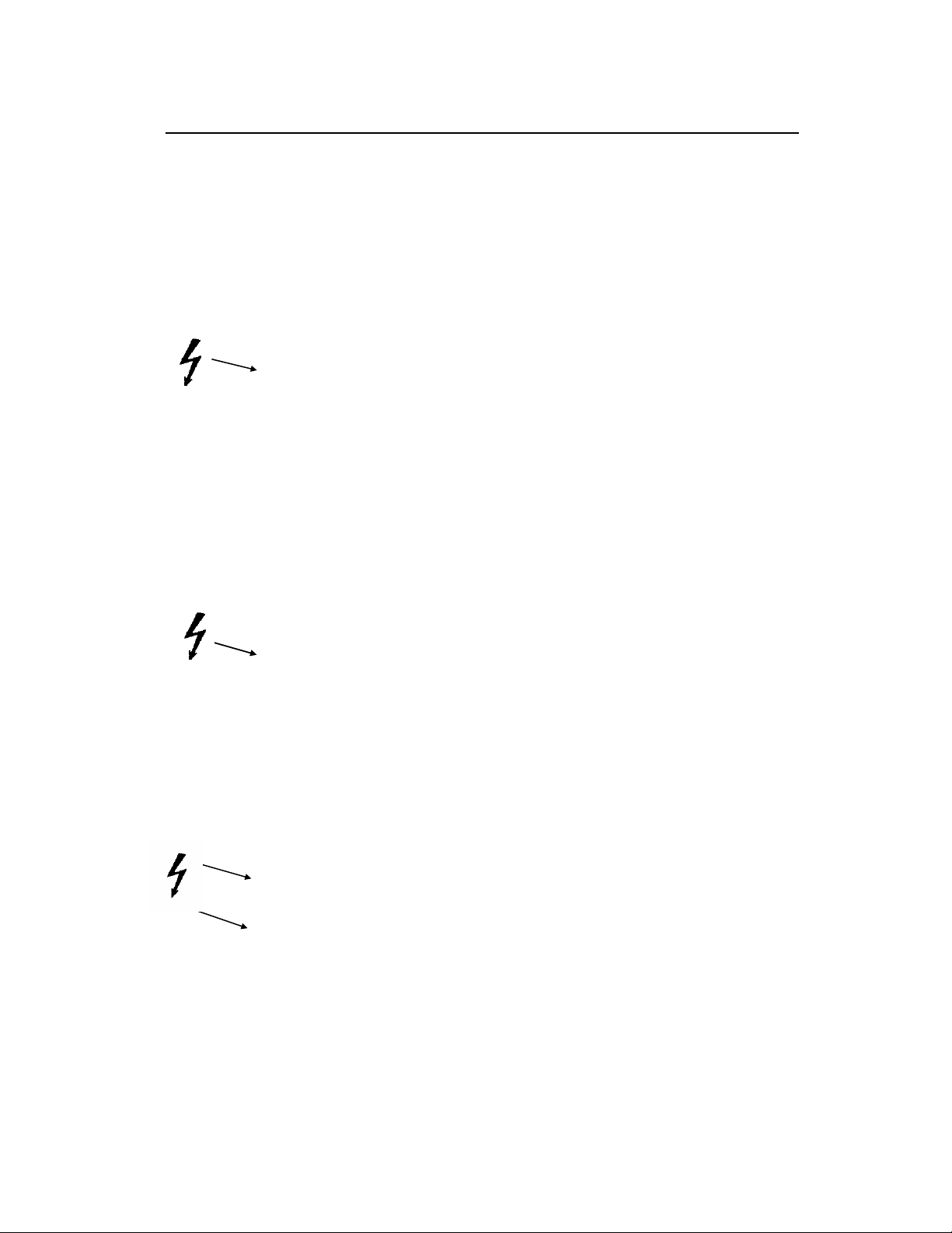
☛ The following warning and informational symbols can be found on the 601PRO:
Symbol Description
Caution: Risk of electric shock
Direct / Alternating Current
Protective Earth (PE)
Caution: Refer to accompanying
documentation
Off (power: disconnection from Mains)
On (Power: connection to Mains)
Equipotential/Functional Earth (FE)
iv
Page 5

NOTICES, WARNINGS AND CONTENT
☛
Exercise extreme caution when a shock hazard is present at the instrument's
measurement terminals during the following tests:
• Mains on Applied Part
• Mains on Applied Part Calibration
• Protective Earth Resistance
• Protective Earth Resistance Calibration
• Equivalent Patient Leakage
• Equivalent Device Leakage
• Equivalent Device/Patient Leakage Calibration
FOR CORRECT OPERATION, ALL GROUND-REFERENCED PERIPHERALS, SUCH AS
PRINTERS AND PCs, MUST BE DISCONNECTED.
Do not discharge a defibrillator while it is plugged into the 601PRO.
☛
☛ Only use Fluke Biomedical-supplied test leads or leads rated for 32 Amps/1000
Volts with the Protective Earth Resistance Test.
☛ Inspect the lead ends for possible wear, cracks or breaks before each use.
☛ Take leakage current measurements only after earth resistance is measured and
found to be compliant with the applied safety limit.
☛ External devices, such as printers and computers, attached to the 601PRO, may
affect the 601PRO's ability to sense Open Earth conditions on the Mains input. If
Mains voltage readings are in error, remove all external devices.
☛ If the DUT fails the Earth Resistance test, the operator must discontinue testing and
label the DUT defective.
☛ If any single test fails, the test must be immediately discontinued and the DUT
labeled defective.
☛ Prior to performing an ECG Simulation test, perform an Applied Part Leakage Test.
If the Applied Part Leakage Test yields an instrument-under-test failure, then do not
perform an ECG Simulation Test, as damage to the instrument may occur.
☛ If operating the 601PRO with a variable AC Supply (Variac), it is important to
perform a calibration after changing the Mains Voltage level. Calibration can be
performed from within the Mains On Applied Part, Equivalent Device Leakage, or
Equivalent Patient Leakage tests.
v
Page 6

601PRO SERIES
Nomenclature
Comparable Terminology: International and United States
INTERNATIONAL/IEC U.S./AAMI
L1 Hot
L2 Neutral
Earth Ground
Mains Line Voltage
Applied Parts Patient Leads
Enclosure/Case Chassis
Protective Earth Ground Wire
Earth Leakage Current Leakage in Ground Wire
Enclosure Leakage Chassis Leakage
XL
Patient Leakage Lead Leakage
Patient Auxiliary Leakage between Patient Leads
Mains on Applied Parts Lead Isolation
Insulation Resistance Dielectric Strength or
Insulation Resistance between
Hot and Neutral to Ground
Earth Resistance Ground Wire Resistance
vi
Page 7

NOTICES, WARNINGS AND CONTENT
Hazard Warnings
☛ Warning! Power Rating. The 601PRO's mains power input must be connected to a
power receptacle that provides voltage within the specified rating for the system.
Connection must be made via the Mains Power cord provided by Fluke Biomedical.
Use of an incompatible power receptacle or incorrect Mains Power cord may produce
electrical shock and fire hazards. Acceptable Mains Voltage ranges are 90~VAC to
132~VAC, and 180~VAC to 240~VAC 50/60 Hz. The current ratings for the 601PRO are
as follows:
Europe: <=15A (Fused by 15A circuit breaker)
United Kingdom: <=13A (Fused by 13A fused Mains Power Cord)
Australia: <=10A (Fused by 10A circuit breaker)
☛ Warning! Internal Voltage. Always turn off the power switch and unplug the power
cord before cleaning the 601PRO's outer surface.
☛ Warning! Liquids. Avoid spilling liquids on the analyzer; fluid seepage into internal
components creates a potential shock hazard. Do not operate the instrument if internal
components are exposed to fluid.
Precautions
The following precautions are provided to help you avoid damaging the system:
☛ To power up the 601PRO, place the index finger on the rocker switch and use a
☛ Caution: Service. The 601PRO should be serviced by authorized service personnel.
☛ Caution: Environmental Conditions. Do not expose the system to temperature
☛ Caution: Do Not Immerse. Clean only with a mild detergent, and wipe down
rolling motion to push from "OFF" to "ON." Do NOT forcefully push or snap the
rocker switch. This may cause the unit to shut off.
Only qualified technical personnel should perform troubleshooting and service
procedures on internal components.
extremes. Ambient temperatures should remain between 18-40°C. System
performance may be adversely affected if temperatures fluctuate above or below
this range.
with a gentle cloth.
vii
Page 8

601PRO SERIES
XL
Electromagnetic Interference and Susceptibility
☛ USA FCC CLASS A
Warning: Changes or modifications to this unit not expressly approved by the
manufacturer could void the user's authority to operate the equipment.
This equipment has been tested and found to comply with the limits for a Class A digital
device, pursuant to Part 15 of the FCC Rules.
These limits are designed to provide reasonable protection against harmful interference
when the equipment is operated in a commercial environment. Like all similar equipment,
this equipment generates, uses, and can radiate radio frequency energy and, if not installed
and used in accordance with the instruction manual, may cause harmful interference to
radio communications. Operation of this equipment in a residential area is likely to cause
interference, in which case the user will be required to correct the interference at his own
expense.
☛ Canadian Department of Communications Class A
User Safety
This digital apparatus does not exceed Class A limits for radio emissions from digital
apparatus set out in the Radio Interference Regulations of the Canadian Department of
Communications.
Le present appareil numerique n'met pas du bruits radioelectriques depassant les limites
applicables aux appareils numerique de la Class A prescrites dans le Reglement sur le
brouillage radioelectrique edicte par le ministere des Communications du Canada.
This device has been type tested by an independent laboratory and found to meet the
requirements of the following:
Canadian Standards Association CAN/CSA
C22.2 No.1010.1-1992, “Safety Requirements for Electrical Equipment for
Measurement, Control and Laboratory Use, Part 1: General Requirements”.
UL 3101-1
“Electrical Equipment for Laboratory Use, Part 1: General Requirements”.
viii
Page 9

NOTICES, WARNINGS AND CONTENT
Based on the testing described below, this instrument bears the CE mark.
EC Directive 89/336/EEC Electromagnetic Compatibility
☛ Emissions - CLASS A
The system has been type tested by an independent, accredited testing laboratory and
found to meet the requirements of EN 61326-1:1998 for Radiated Emissions and Line
Conducted Emissions. Verification of compliance was conducted to the limits and
methods of the following:
CISPR 16-1:1993 and CISPR 16-2:1996
☛ Immunity
The system has been type tested by an independent, accredited testing laboratory and
found to meet the requirements of EN 61326-1:1998 for Immunity. Verification of
compliance was conducted to the limits and methods of the following:
EN 61000-4-2 (1991) Electrostatic Discharge
EN 61000-4-3 (1995) Radiated EM Fields
EN 61000-4-4 (1995) Electrical Fast Transient/Burst
EN 61000-4-5 (1995) Surge Immunity
EN 61000-4-6 (1996) Conducted Disturbances
EN 61000-4-11 (1994) Voltage Dips, Short Interruptions and Variations
EC Directive 73/23/EEC Low Voltage (Safety)
The system has been type tested by an independent testing laboratory and found to meet
the requirements of EC Directive 73/23/EEC for Low Voltage. Verification of compliance
was conducted to the limits and methods of the following:
EN 61010-1 (1993) & IEC 1010-1
“Safety Requirements for Electrical Equipment for Measurement, Control and
Laboratory Use, Part 1: General requirements” (including amendments 1 & 2).
ix
Page 10

601PRO SERIES
Warranty
XL
This Warranty is limited and applies only to new products, except for computerbased software, which is covered under a separate Warranty Policy,
manufactured by Fluke Biomedical. Fluke Biomedical makes no warranty
statement regarding the condition of used products.
Fluke Biomedical warrants the instrument (hereinafter collectively referred to as
“Products” or “Product”) for a period of one (1) year from the original purchase
date against defective materials or workmanship. This Warranty is limited to the
original purchaser (the “Purchaser”) and cannot be assigned or transferred. All
claims under this Limited Warranty must be made in writing to Fluke Biomedical,
Attention: Service Department. Purchaser must ship the Product to Fluke
Biomedical, postage pre-paid. Fluke Biomedical shall either repair or replace with
new or like new, at its option and without cost to the Purchaser, any Product
which in Fluke Biomedical’s sole judgment is defective by reason of defects in the
materials or workmanship.
This Warranty is VOID if the Product has been damaged by accident or misuse, or
has been damaged by abuse or negligence in the operation or maintenance of the
Product, including without limitation unsafe operation, operation by untrained
personnel, and failure to perform routine maintenance. This Warranty is VOID if
the Product has been repaired or altered by persons not authorized by Fluke
Biomedical, or if the Product has had the serial number altered, effaced, or
removed. This Warranty is VOID if any of the Products has not been connected,
installed or adjusted strictly in accordance with written directions furnished by
Fluke Biomedical. Batteries, fuses, light bulbs, and other “consumable” items used
in any of the Products are not covered by this Warranty. Software utilized in
conjunction with any of the Products is not covered by the terms of this Warranty
but may be covered under a separate Fluke Biomedical software warranty.
We will continue to stock parts for a maximum period of five (5) years after the
manufacture of any equipment has been discontinued. Parts shall include all
materials, charts, instructions, diagrams, and accessories that were furnished with
the standard models.
THIS WARRANTY CONTAINS THE ENTIRE OBLIGATION OF FLUKE
BIOMEDICAL, AND NO OTHER WARRANTIES, EXPRESSED, IMPLIED, OR
STATUTORY ARE GIVEN. PURCHASER AGREES TO ASSUME ALL LIABILITY
FOR ANY DAMAGES AND/OR BODILY INJURY OR DEATH THAT MAY
RESULT FROM THE USE OR MISUSE OF ANY EQUIPMENT OR
INSTRUMENT BY THE PURCHASER, HIS EMPLOYEES, AGENTS, OR
CUSTOMERS, OTHER THAN THE EXPRESS WARRANTY CONTAINED
HEREIN. WE SHALL NOT BE RESPONSIBLE FOR ANY DIRECT OR
CONSEQUENTIAL DAMAGES OF ANY KIND. THIS WARRANTY SHALL NOT
BE CHANGED OR MODIFIED IN ANY WAY WITHOUT THE EXPRESS
WRITTEN PERMISSION OF AN OFFICER OF FLUKE BIOMEDICAL.
THIS WARRANTY IS VOID UNLESS THE PURCHASE REGISTRATION CARD
HAS BEEN COMPLETED AND MAILED TO US WITHIN TEN (10) DAYS OF
PURCHASE.
x
Page 11

Contents
NOTICES, WARNINGS AND CONTENT
Notices ....................................................................................................ii
Warnings ...............................................................................................iii
Nomenclature ......................................................................................... v
Hazard Warnings ................................................................................... vi
Precautions ............................................................................................. vi
Electromagnetic Interference and Susceptibility................................... vii
Safety.....................................................................................................vii
Warranty................................................................................................. ix
Chapter 1: Introduction and Description
Introduction to the 601PRO Series
Accessories........................................................................................... 1-3
Optional Accessories............................................................................1-3
Menu Structure.....................................................................................1-3
System Characteristics .........................................................................1-5
Audio Feedback ................................................................................ 1-5
Top Panel ..........................................................................................1-6
Keys Used to Enter Device Control Numbers ..................................1-7
Front Panel........................................................................................1-8
Back Panel ........................................................................................1-9
Statement of Compatibility.............................................................1-10
Chapter 2: Setting Up the 601PRO
Using Factory Default Settings ............................................................2-1
Selecting the Test Standard ..................................................................2-2
Selecting the Printer Output ................................................................. 2-3
Selecting the RS232 Baud Rate ...........................................................2-4
...................................................1-1
XL
Activating the Beeper...........................................................................2-5
Setting the Time and Date....................................................................2-6
Configuring the Enclosure Leakage for the Auto Mode Sequence......2-8
Selecting Language Options.................................................................2-9
Selecting the DC Option ....................................................................2-10
Selecting the Auto/Step Tests: Controlled Power Sequences or
601CE Conventional Test Sequences ............................................2-11
Enabling Stop on Failure.................................................................... 2-13
Configuring for Device Records or Templates ..................................2-15
xi
Page 12

601PRO SERIES
Chapter 3: Manual Mode
XL
Connecting the Device Under Test ......................................................3-1
The Power-Up Sequence......................................................................3-2
Selecting the Test Standard ..................................................................3-3
Selecting the Class/Type ...................................................................... 3-4
Saving Standard, Class, Type and Test Current...................................3-6
Using View Present Settings ................................................................3-7
Lead Type Definitions ......................................................................3-9
Manual Operation...............................................................................3-13
Additional Features.........................................................................3-14
Shortcut Key 0: Mains Voltage Test and
Dual Lead Voltage Test ..................................................................3-16
Shortcut Key 1: Current Consumption Test....................................3-17
Shortcut Key 2: Insulation Resistance Test ....................................3-18
Shortcut Key 3: Protective Earth Resistance Test ..........................3-20
Shortcut Key 4: Earth Leakage Test ............................................... 3-22
Shortcut Key 5: Enclosure Leakage Test........................................3-23
Shortcut Key 6: Patient Leakage Current Test
(IEC 601-1 or VDE 751-1 Test Standard) ...................................... 3-24
Shortcut Key 7: Mains on Applied Part Leakage Test
(IEC 601-1).....................................................................................3-26
Shortcut Key 8: Patient Auxiliary Current Test.............................. 3-28
Shortcut Key 9: IEC 1010 Accessible Voltage/
Leakage Test ...................................................................................3-30
Accessible Voltage......................................................................3-30
Accessible Leakage .....................................................................3-31
Shortcut Key /: VDE Equivalent Device Leakage Test..................3-32
Shortcut Key
- : VDE Equivalent Patient Leakage Test................3-34
Dual Lead Leakage ......................................................................... 3-36
ECG Output ....................................................................................3-37
Sample Waveforms ..................................................................... 3-38
xii
Page 13

NOTICES, WARNINGS AND CONTENT
Chapter 4: Auto/Step Modes
Selecting Auto or Step Mode Testing ..................................................4-1
Executing Auto and Step Mode Tests ..................................................4-4
Creating/Editing a Device Record or Template ...................................4-7
Chapter 5: Test Records
Sending Test Results from the 601PRO to the Host Computer ...........5-1
Test Data Record: Serial Output ..........................................................5-3
Printing Test Records...........................................................................5-3
Deleting Test Records .......................................................................... 5-3
Printing a Header...........................................................................5-5
Chapter 6: Device Records and Templates
Setup Requirements..............................................................................6-1
Using the Device Information Record Utility ...................................... 6-1
Connecting the 601PRO and the Host Computer.................................6-2
Sending Device Information Records from the 601PRO
to the Host Computer ...........................................................................6-2
Receiving Device Information Records from the Host Computer ....... 6-3
Device Information Record: Definition of Fields ................................6-5
Device Information Record Format .....................................................6-6
Deleting Device Records and Templates .............................................6-7
Chapter 7: Testing Devices
Permanently Wired Devices.................................................................7-1
Portable Devices ..................................................................................7-2
Portable Devices in Isolated Power Systems .......................................7-2
Testing Three-Phase Portable Devices.................................................7-2
Testing Conductive Surfaces................................................................7-3
Detachable Power Supply Cable ..........................................................7-3
Battery-Powered Equipment ................................................................7-3
xiii
Page 14

601PRO SERIES
Chapter 8: Standards and Principles
Chapter 9: Custom Standards
Chapter 10: Computer Control
XL
Accessing System Setup.......................................................................8-2
Selecting the Test Standard ..................................................................8-2
Referring to Test Limits for the Selected Standard..............................8-2
Defining/Editing a Custom Standard ...................................................9-1
Tests Available in a Custom Standard .................................................9-4
Custom Standard Controlled Power Sequence.....................................9-5
Setup Requirements............................................................................10-1
Establishing Computer Control..........................................................10-2
Connecting the 601PRO and the Host Computer........................10-2
Sending the Command from the Host Computer ........................10-2
Command Protocol.............................................................................10-2
Computer Control Commands............................................................10-4
Chapter 11: Error Messages, Troubleshooting, and Support
Error Codes ........................................................................................11-1
Errors and Suggested Corrective Actions ..........................................11-2
Troubleshooting .................................................................................11-3
Technical Assistance ..........................................................................11-3
Service................................................................................................11-3
Shipping Requirements ............................................................... 11-3
Appendix A: Specifications
Appendix B: Keyboard Options/Barcode Keyboard Wedge
Appendix C: Printer Maintenance
Appendix D: Test Data Record ASCII Character Formats
xiv
Page 15

Introduction and Description
Chapter
1
1. Introduction to the 601PRO SeriesXL
2. Accessories
3. Optional Accessories
4. Menu Structure
5. System Characteristics
6. Statement of Compatibility
1. Introduction to the 601PRO SeriesXL
The 601PRO SeriesXL (601PRO) is an automated electrical safety analyzer that
meets stringent international standards for electrical safety testing of hospital
and laboratory electromedical equipment.
The 601PRO conducts electrical safety testing in accordance with IEC 601-1,
VDE 751, VDE 701, HEI 95, IEC 1010, AAMI, and AS/NZS 3551
requirements, flags failures, and simulates performance, ECG, and arrhythmia
waveforms. The 601PRO stores 1000 device records. Test results, which are
automatically analyzed and saved in non-volatile memory, can be printed using
the internal ZY column thermal printer or an attached external printer, or
uploaded to a PC using the serial port.
The 601PRO offers automatic, manual, computer control, or step mode
operation.
The 601PRO will accept device information that is input using an external
keyboard, integrated keypad, or barcode keyboard wedge.
1-1
Page 16

601PRO SERIES
XL
Available electrical safety tests include:
♦ Mains Voltage
♦ Dual Lead Voltage
♦ Dual Lead Leakage
♦ Current Consumption
♦ Insulation Resistance
♦ Protective Earth Resistance
♦ Earth Leakage Current
♦ Enclosure Leakage Current
♦ Patient Leakage Current
♦ Mains on Applied Part Leakage
♦ Patient Auxiliary Current
♦ Accessible Voltage
♦ Accessible Leakage
♦ Equivalent Device Leakage
♦ Equivalent Patient Leakage
Available ECG performance waveforms include:
♦ Square wave: 0.125, 2 Hz
♦ Sine wave: 10, 40, 50, 60, 100 Hz
♦ Triangle wave: 2 Hz
♦ ECG complex: 30, 60, 120, 180, 240 BPM
♦ Pulse: 30, 60 BPM
♦ A-Fib, A-Flutter, A-Tach, Idioventricular,
PVC1, R-on-T, Run, V-Fib, V-Tach
1-2
Page 17

INTRODUCTION AND DESCRIPTION
2. Accessories
The following accessories are shipped standard with the 601PRO. To order
additional quantities, contact your Fluke Biomedical equipment dealer, and use
the Fluke Biomedical Part Numbers provided.
Description Quantity
Supplied
Probe/Safety Lead, Red 1 2213252
Probe/Safety Lead, Black 1 2213241
Adapter, Banana/Alligator 5 2212941
Operators Manual 1 2234222
Large Clamp, Red 1 2004125
Warranty Card 1 2241856
Printer Paper Roll (original) 1 2248719
Printer Paper Roll (new style) 1 2248743
Part #
3. Optional Accessories
The following optional accessories are available for the 601PROXL. To order,
contact a Fluke Biomedical equipment dealer and use the Fluke Biomedical
part numbers provided.
Description Part #
Carry Case 2234065
RS232 Cable (9M-9F) 2238659
Printer Cable 2238072
Barcode, Keyboard, Wedge 2248255
Adapter, Banana, ECG 2212657
Keyboard English 2213184
Powercord Set Australian 2238603
Powercord Set Schuko 2238015
Powercord Set US 120 V 2286644
Powercord Set UK 2238570
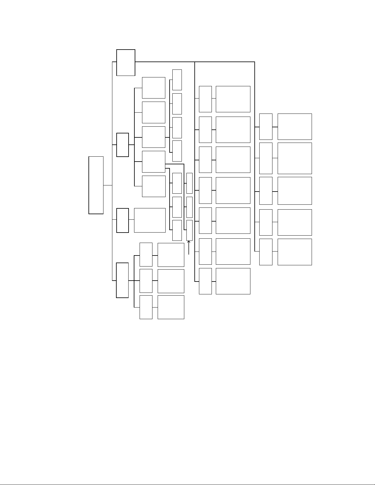
4. Menu Structure
A layout showing various system functions is provided on the following page.
1-3
Page 18
601PRO SERIES
XL
SETUP
SYSTEM
(CHAPTER 2)
PRINT
(CHAPTER 2)
PRINTDELETE
(CHAPTER 9)
SUMMARY
LEAKAGE
ENCLOSURE
CONFIGURE
ENCLOSURE
LEAKAGE FOR
USE DURING
AUTO MODE
SEQUENCE
TEST
TEST
ENABLE
STANDARDS
EDIT
CUSTOM
STANDARD
MAIN MENU
CLASS/TYPE UTILITIES
TESTS/
AUTOMODES
TEST
DEVICE
SYSTEM
SELECT
ALL VALID
CLASS/TYPES
MANUAL
STEP
RECORDS
OR
RECORDS
TEMPLATES
TEST
FOR THIS
PRESENT
STANDARD
(CHAPTER 3)
(CHAPTER 4)
(CHAPTER 5)
(CHAPTER 6)
CREATE
(CHAPTER 3)
(CHAPTER 3)
SELECT
TEST AND
ADVANCE TO
SELECTED
SCREEN
ENTER
CONTROL
NO. TO
STEP
THROUGH
TRANSMIT
(CHAPTER 4)
RECEIVE
EDIT DELETE ALLDELETE
TRANSMIT
CHAPTER 4
EACH TEST
DATE
FORMAT
TIME
FORMAT
BEEPER
RS232
OUTPUT
PRINTER
TEST
STANDARD
SET DATE
TO EITHER
MM-DD-YYORDD-MM-YY
SET CLOCK
TO EITHER
12-HOUR OR
24-HOUR
FORMAT
ACTIVATE OR
DEACTIVATE
BEEPER
CONFIGURE
RS232 SERIAL
PORT FOR:
- EXTERNAL
RS232
SELECT AND
SET UP
PRINTER
INTERFACE
SELECT FROM
- IEC 601-1
- VDE 701-1
- VDE 751-1
- HEI 95
FORMAT
DEVICE
- IEC 1010
- AAMI
- AS/NZS 3551
- CUSTOM
DEV RECS/
TEMPLATES
ON
STOP
FAILURE
SELECT
AUTO/STEP
SEQUENCES
DC
LANGUAGE
CONFIGURE
FOR DEVICE
RECORDS OR
TEMPLATES
AUTOMATICALLY
STOPS AN AUTO
MODE SEQUENCE
WHEN A TEST
FAILS
SELECT
CONTROLLED
POWER
SEQUENCE
OR 601CE
ENABLE DC
READINGS
SELECT
KEYBOARD
OR DISPLAY
LANGUAGE:
CONVENTIONAL
TEST
SEQUENCE
- ENGLISH
- FRENCH
- GERMAN
- ITALIAN
1-4
AUTO
(CHAPTER 4)
ENTER
CONTROL
NO. TO
PERFORM
COMPLETE
TEST
baw007f.eps
Page 19

INTRODUCTION AND DESCRIPTION
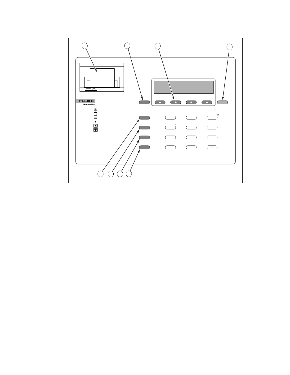
5. System Characteristics
The 601PRO uses a membrane keypad for selection of tests or menu options.
The keys are grouped by color and functionality. The red keys below the
display are used to access menu options. These include the
SOFT KEYS, and the enter key. The black keys allow the operator to
four
gain access to additional functions. These include the
present settings
key, the print header key, and the print data key.
previous key, the
esc/stop key, the view
The red keys numbered 0 through
– are used to enter information and can also
be used to gain quick access to the manual tests.
AUDIO FEEDBACK
• A one-beep signal indicates that a key has been pressed.
• A two-beep-per-second signal indicates high voltage or current generated
by the 601PRO is present.
1-5
Page 20
601PRO SERIES
XL
A
601 Pro Series
XL
INTERNATIONAL SAFETY ANALYZER
CLASS I PROTECTIVE EARTH
CLASS II
CLASS IP
TYPE B NON-ISOLATED APPLIED PART
TYPE BF ISOLATED APPLIED PART
TYPE CF
TYPE F
TYPE T
DOUBLE INSULATION
INTERNAL POWER SUPPLY
ISOLATED APPLIED PART
DIRECT CARDIAC APPLICATION
FIXED DEVICE
TRANSPORTABLE DEVICE
E
F
Figure 1-1: 601PRO Top Panel Illustration
B
G H
PREVIOUS
ESC/STOP
VIEW PRESENT
SETTINGS
PRINT HEADER
PRINT DATA
C
VOLTS-V
PROTECTIVE EARTH
RESISTANCE-
34
PATIENT
LEAKAGE-µA
IEC 1010
ACCESSIBLE-V/µA
9
TESTS
TESTS
CURRENT-A
10
EARTH
LEAKAGE-µA
MAINS ON AP
LEAKAGE-µA
76
VDE EQUIVALENT
DEVICE LEAK-µA
/
INSULATION-M
2
ENCLOSURE
LEAKAGE-µA
5
PATIENT AUXILIARY
CURRENT-µA
8
VDE EQUIVALENT
PATIENT LEAK-µA
ENT
D
Baw152f.eps
Top Panel: Identifying 601PRO Components
Use the drawing of the 601PRO top panel, displayed above, to locate the
following components.
A Printer
Optional 24-character printer for
immediate hard copy of results.
B Previous Key
C
Soft Keys 1-4
Returns user to the previous screen.
Make dynamic assignments based on
current screen.
Enter Key
D
Advances to the next menu or
saves/selects options.
E
Esc/Stop Key
Discontinues current test and returns
operator to the
the DUT outlet.
F
View Present
Settings Key
Advances to View Present Settings
screen when at the
Displays current settings and allows
operator to edit test standard, class/type,
and lead assignments (see page 3-7).
G
Print Header Key
Sends device information fields to
enabled printer.
H
Print Data Key
Sends displayed test data to printer.
MAIN MENU. Turns off
MAIN MENU.
1-6
Page 21
INTRODUCTION AND DESCRIPTION
Keys Used to Enter Device Control Numbers
The keys described below (0 through –) can be used to enter test control
numbers in the auto/step modes of operation. These keys are also referred to as
test-shortcut keys and can be used to initiate manual tests.
0 Volts In single lead mode, displays mains voltage.
In dual lead mode, displays voltage between
RED and BLACK test leads.
1 Current Measures the current consumption (in
amperes) of the device under test.
2
3 Protective Earth
4 Earth Leakage Is measured between the DUT “Protective
5 Enclosure Leakage In single-lead mode, measures the enclosure
6
Patient
7 Mains on
8 Patient Auxiliary
9 IEC 1010
Insulation Tests insulation resistance (mains to case or
applied parts to case).
Measures the earth resistance using a 1A test
Resistance
Leakage
Applied Part
Leakage
Current
Accessible
Voltage/Leakage
current (unless 10A or 25A is selected).
Earth” terminal and the “Protective Earth”
terminal of the 601PRO.
leakage (RED test lead to DUT protective
earth on the 601PRO).
Measures the patient leakage current (applied
part to earth.
Applies 110% mains voltage to selected
applied part and measures leakage to earth in
both normal and reverse polarity. Does not
apply to patient auxiliary selections.
Measures the leakage and biasing current
between applied parts.
Selects the IEC 1010 Test Load. Measures
accessible voltage through the RED jack to
601PRO earth. Allows access to the
accessible leakage test.
/ VDE Equivalent
Device Leakage
– VDE Equivalent
Patient Leakage
Selects the IEC 601 test load. Applies 110%
of mains voltage between L1/L2 and earth.
Selects the IEC 601 test load. Applies 110%
of mains voltage to the selected applied part
and measures the leakage.
1-7
Page 22
601PRO SERIES
XL
B
A
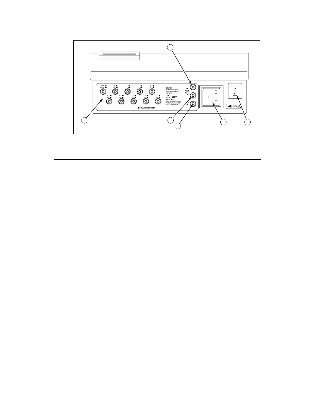
Front Panel
A Applied Part
B Red Input
C Black Input
D Green Input
E Power Outlet Allows standard power plug connection
C
D
Figure 1-2: 601PRO Front Panel Illustration
The jacks allow direct connection to
Terminal
banana jacks, or 4mm-to-alligator
adapters provided.
Single test lead connection.
Terminal
Used for dual lead testing in combination
Terminal
with red test lead.
Protective Earth of Device Under Test.
Terminal
of the Device Under Test. 120V @ 15A
or 240V @ 15A maximum.
E F
baw154f.eps
1-8
F On-Off Switch /
Circuit Breaker
Power up the 601PRO, I=ON, 0=OFF;
built-in ISA circuit breaker.
Note: To power up the 601PRO, place
the index finger on the rocker switch and
use a rolling motion to push from "OFF"
to "ON." Do NOT forcefully push or
snap the rocker switch. This may cause
the unit to shut off.
Page 23
INTRODUCTION AND DESCRIPTION
D
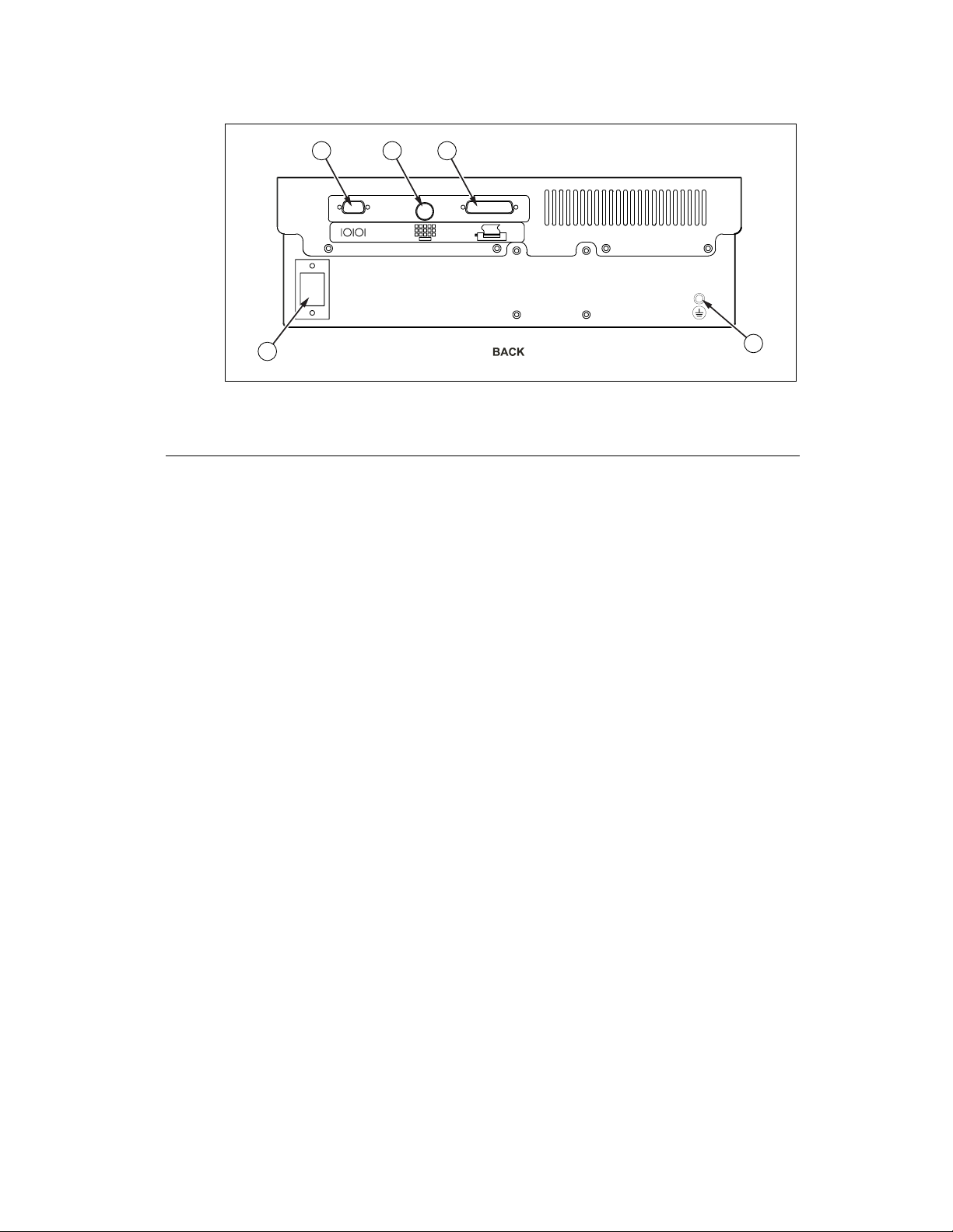
Back Panel
A RS232 Connection Allows bi-directional computer control.
B Keyboard Input Allows the use of an external keyboard
A
B C
E
baw155f.eps
Figure 1-3: 601PRO Back Panel Illustration
Serial D-9 female connector.
for data input. DIN 5 socket.
C Printer Connector Allows for an external parallel printer.
D-25 female connector.
D Power Cord
Connection
E Protective Earth
Connection
120V/15A or 240V/15A power cord
connection.
Provides a direct connection to the
power cord ground.
1-9
Page 24

601PRO SERIES
6. Statement of Compatibility
XL
The 601PRO is compatible with and has the same base features as the previous
601PRO safety analyzer. It also has some new features that include the
following:
• Because of new features in this version of the 601PRO, the Device Record
Format has been changed. If old format device records are transmitted to
the 601PRO Series
via RS232, they will be accepted. However, when
XL
receiving device records from the 601PRO, the new format will always be
used. Refer to Chapter 6 for details.
• Custom standard names are fixed. Any old-style device record received via
RS232 must be updated to reflect this change. Refer to Chapter 9 for more
details.
• Supports all computer control commands from the previous 601PRO.
Some of the commands no longer have meaning in the new 601PRO and
have been given fixed responses. New commands have been added to
support new features on the instrument. Refer to Chapter 10 for complete
details.
• Due to new features, the RS232 result output format has changed. It is very
similar to the old format but has extra fields for the new features. The
transfer utility is no longer required or supported. Refer to Chapter 5
for complete details.
• Because the 601PRO now supports IEC 601, IEC 1010, and AAMI test
loads, some changes in computer control commands have been made. All
existing (previous) commands use the 601 test load. New commands have
been created to support the new loads. Refer to Chapter 10 for details.
• Unlike previous versions of the 601PRO, the 601PRO Series
XL
standard D9M-D9F serial cable.
uses a
1-10
Page 25
Setting Up the 601PRO
Chapter
2
This chapter describes the factory default settings and how to change them,
and provides instructions for one-time customization of the 601PROXL using
SYSTEM SETUP key and the Select Setup Function menu.
the
1. Using Factory Default Settings
2. Selecting the Test Standard
3. Selecting the Printer Output
4. Selecting the RS232 Baud Rate
5. Activating the Beeper
6. Setting the Time and Date
7. Configuring the Enclosure Leakage for the Auto
Mode Sequence
8. Selecting Language Options
9. Selecting the DC Option
10. Selecting the Auto/Step Tests: Controlled Power
Sequences or 601CE Conventional Test
Sequences
11. Enabling Stop on Failure
12. Configuring for Device Records or Templates
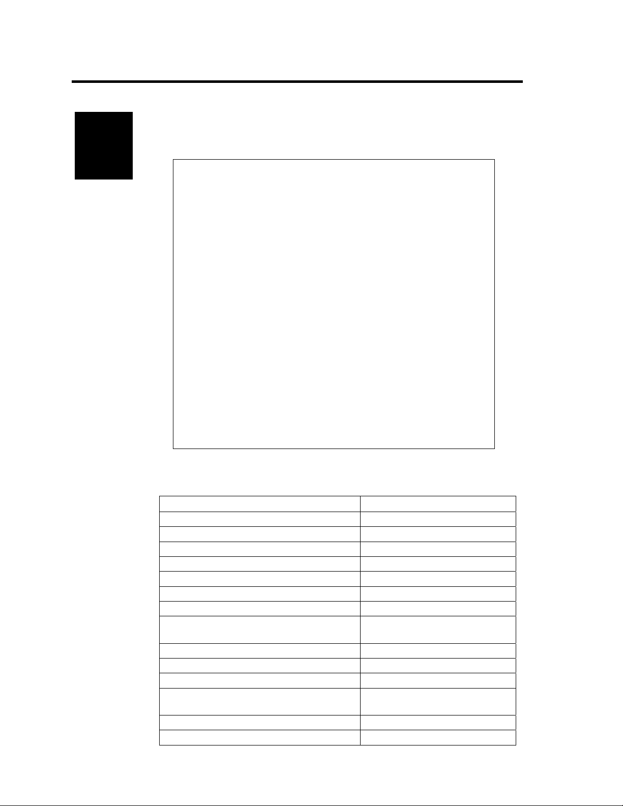
1. Using Factory Default Settings
The factory default settings are shown below.
Description Factory Default Setting
Test Standard IEC 601-1 (Class I, BF)
Number of Applied Parts 0 (To change, refer to Chapter 3)
Printer Output Internal
RS232 9600 Baud
Beeper On
Time Format 24 hour
Date Format MDY
Enclosure Leakage (multiple readings
during the Auto Mode sequence)
Keyboard Language English
Display/Print Language English
DC Readings Off
Auto/Step Sequences: Controlled Power
Sequence
Stop on Failure Off
DEV RECS / TEMPLATES DEVICE REC
Off
On
2-1
Page 26
601PRO SERIESXL
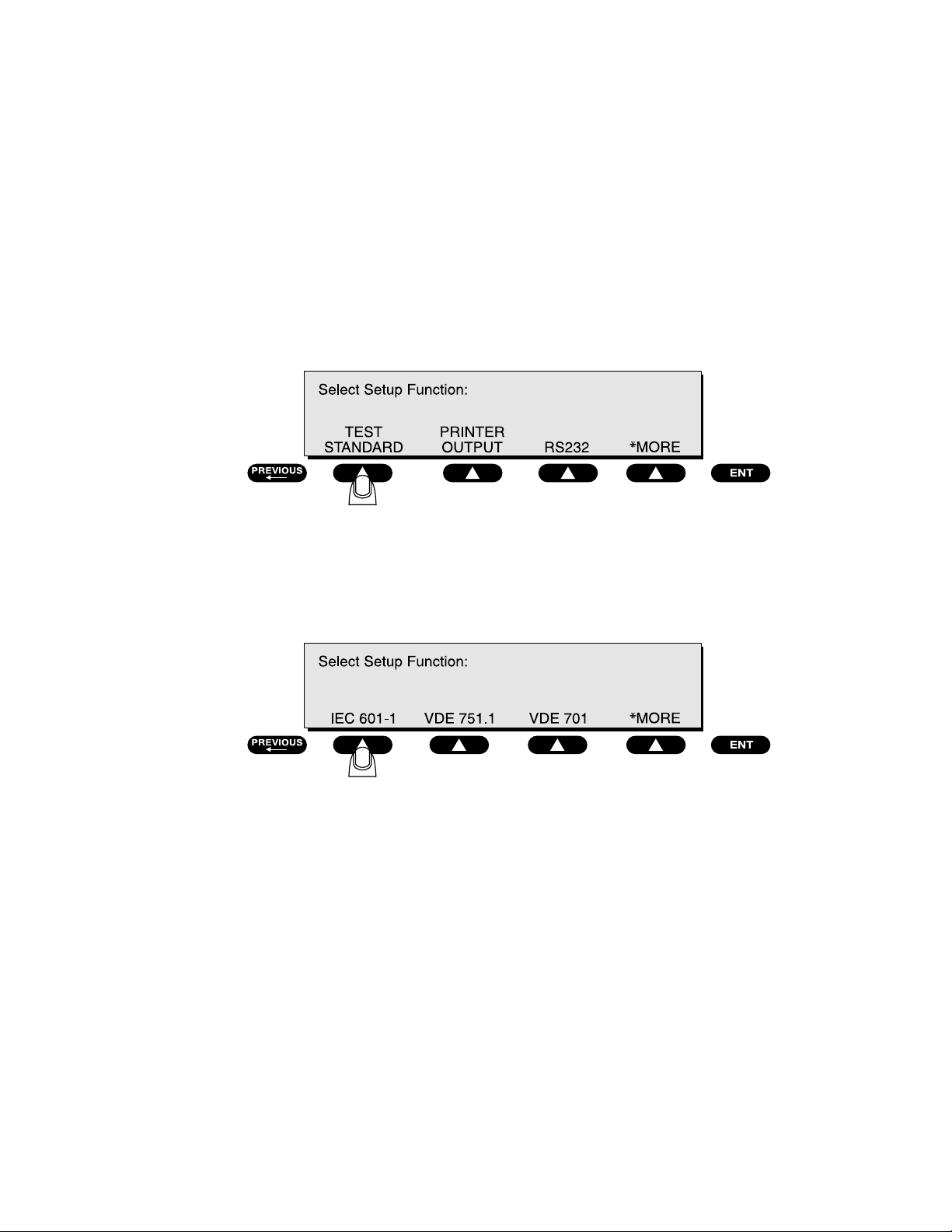
2. Selecting the Test Standard
The Select Test Standard option allows the operator to choose among
IEC 601-1, VDE 701-1, VDE 751-1, HEI 95, IEC 1010, AAMI,
AS/NZS 3551, or custom standards.
Refer to Chapter 8, Standards and Principles, for a detailed discussion of IEC
601-1, VDE 701-1, VDE 751-1, HEI 95, IEC 1010, AAMI, and AS/NZS 3551
standards and their selection.
• At the 601PRO
Setup Function
• At the
Select Test Standard menu, select a test standard, or press *MORE
for additional standards.
MAIN MENU, press SYSTEM SETUP to access the Select
menu. Press TEST STANDARD:
baw008f.eps
2-2
☛ Note: To enable/disable the test standards that appear at the
Standard
*MORE
Enable Test Standard menu.
menu, press UTILITIES at the MAIN MENU, then
, then ENABLE STANDARDS. Press YES or NO at the
Once the selection is made, the 601PRO will automatically return
MAIN MENU where the selected standard is displayed.
to the
Default Setting: IEC 601-1
baw009f.eps
Select Test
Page 27
SETTING UP THE 601PRO
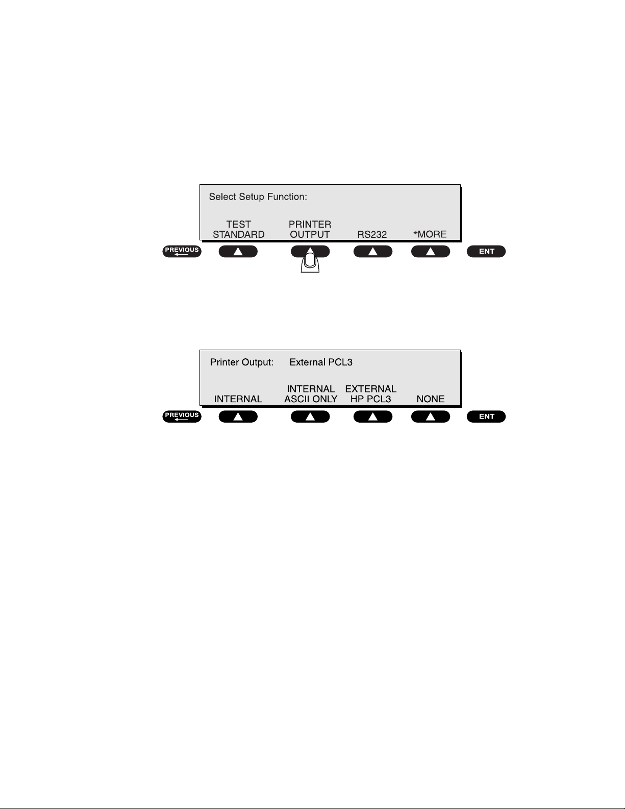
3. Selecting the Printer Output
Before testing, choose whether to use the optional internal printer, an external
printer, or no printer.
• From the 601PRO
Select Setup Function menu. Press PRINTER OUTPUT:
• At the
Printer Output menu, use the SOFT KEYS to select a printer
interface:
MAIN MENU, press SYSTEM SETUP to access the
baw026f.eps
baw010f.eps
⇒ The EXTERNAL ASCII ONLY setting is for older (and some newer)
printers that will interpret and print basic ASCII characters.
⇒ The EXTERNAL HP PCL3 printer setting is for any HP printer that
supports PCL3 (Printer Control Language, Version 3). The control
sequence feature configures the printer and then downloads ASCII
characters to it.
☛ Note: Follow the printer manufacturer’s instructions for handling page
ejects and printing using form-feed commands.
• Press
Default Setting: Internal
previous or enter to save the settings and return to the MAIN MENU.
2-3
Page 28
601PRO SERIESXL
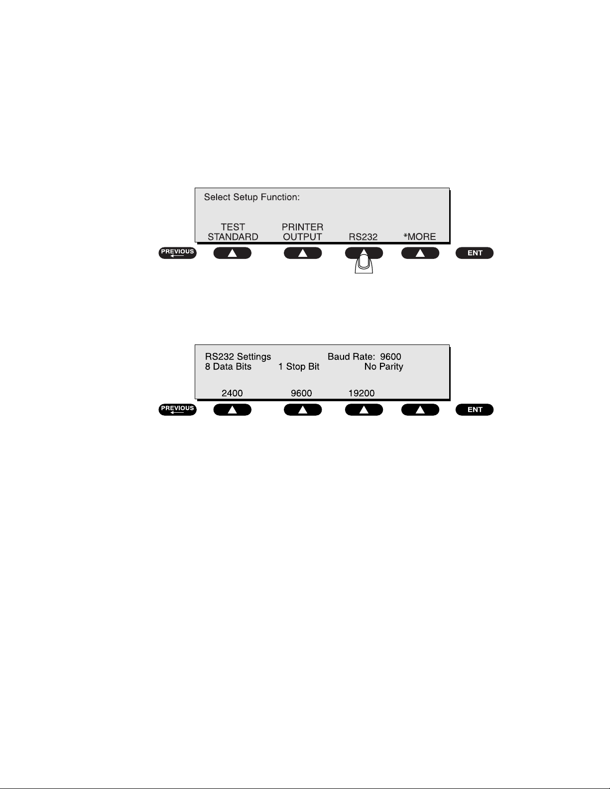
4. Selecting the RS232 Baud Rate
To select the baud rate for the RS232 serial port:
• From the 601PRO
Select Setup Function menu. Press RS232:
At the 601PRO
RS232 Settings menu, press a SOFT KEY to select a baud rate:
MAIN MENU, press SYSTEM SETUP to access the
baw027f.eps
Default Setting: 9600
• Press
enter to save the setting and return to the Select Setup Function
menu. Press
previous to return to the MAIN MENU.
baw011f.eps
2-4
Page 29
SETTING UP THE 601PRO
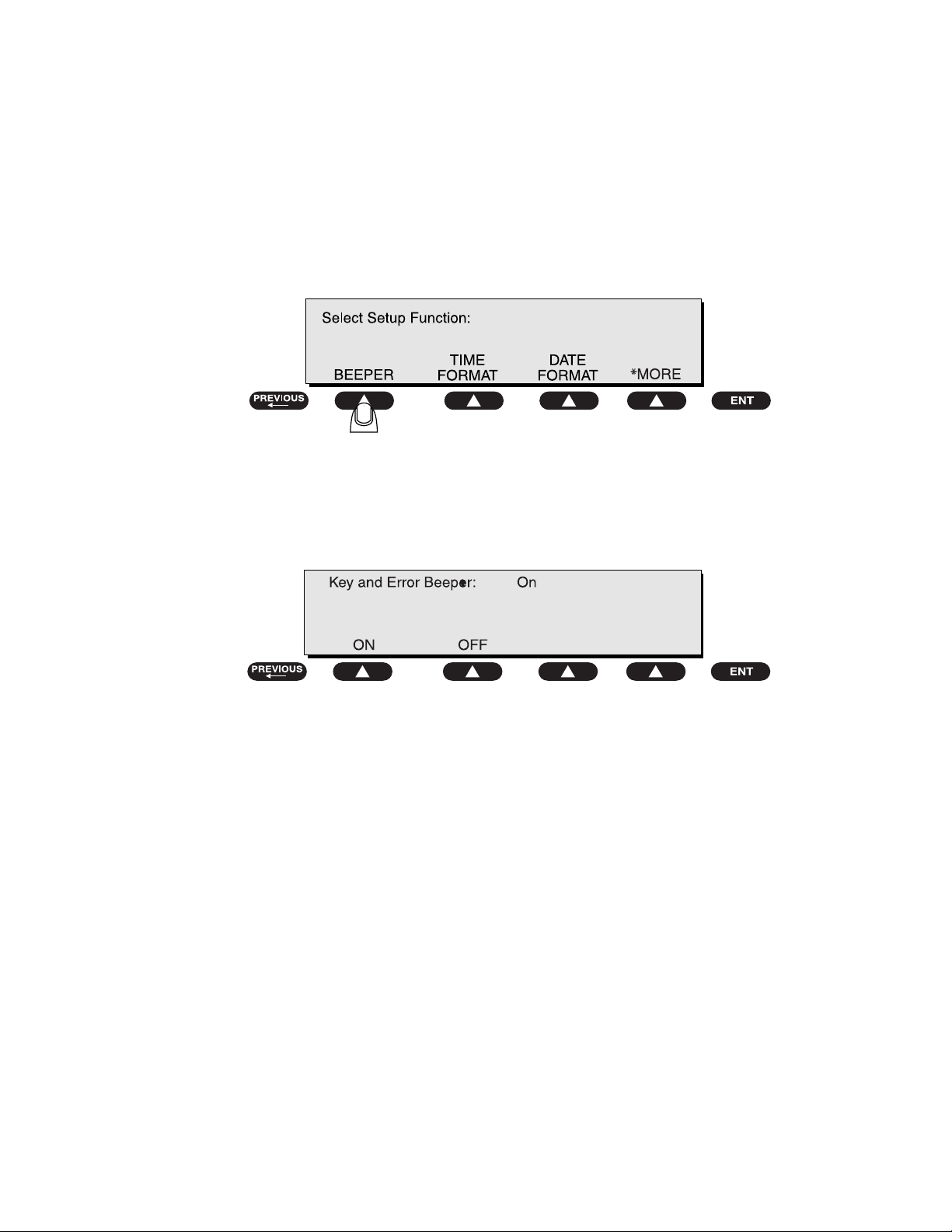
5. Activating the Beeper
To activate/deactivate the beeper:
• From the 601PRO
Select Setup Function menu. Press *MORE until the following menu is
displayed, then press
MAIN MENU, press SYSTEM SETUP to access the
BEEPER:
• Press a
SOFT KEY to select ON or OFF at the Key and Error Beeper
menu:
baw012f.eps
baw025f.eps
Selecting
an error occurs. Selecting
OFF will silence the beep that sounds when a key is pressed or when
OFF will not disable the beeper during lead
calibration or when performing tests using the beeper as a warning.
Default Setting: ON
• Press enter to save the settings and return to the Select Setup Function
menu. Press
previous to return to the MAIN MENU.
2-5
Page 30
601PRO SERIESXL
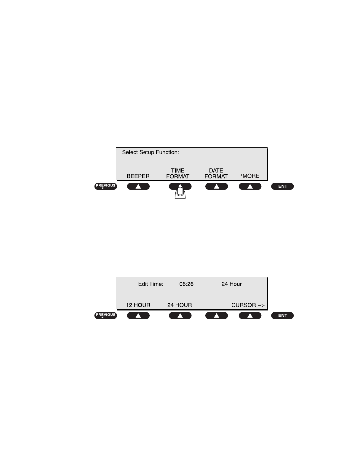
6. Setting the Time and Date
The time and date are used to record testing times and their associated dates.
The clock can be set in either 12-hour or 24-hour format. The date format is
either MM-DD-YY or DD-MM-YY.
To set the time format:
• From the 601PRO
Select Setup Function menu. Press *MORE until the following menu is
displayed, then press
MAIN MENU, press SYSTEM SETUP to access the
TIME FORMAT:
To set the time:
• At the following menu, press a
24 HOUR format. Press the cursor SOFT KEY to change cursor position
and enter the time of day using the
SOFT KEY to select either the 12 HOUR or
test-shortcut keys.
baw028f.eps
2-6
Default Setting: 24 HOUR
• Press
enter to save the settings and return to the Select Setup Function
menu. Press
previous to return to the MAIN MENU.
baw013f.eps
Page 31

SETTING UP THE 601PRO
To set the date format:
• From the 601PRO
Select Setup Function menu. Press *MORE until the following menu is
displayed, then press
MAIN MENU, press SYSTEM SETUP to access the
DATE FORMAT:
To set the date:
• At the following menu, press a
DD/MM/YY. Press a SOFT KEY to move the cursor in either direction. Use
test-shortcut keys to enter the date.
the
SOFT KEY to select either MM/DD/YY or
baw029f.eps
Default Setting: MDY
• Press
enter to save the settings and return to the Select Setup Function
menu. Press
previous to return to the MAIN MENU.
baw014f.eps
2-7
Page 32

601PRO SERIESXL
7. Configuring the Enclosure Leakage for the Auto Mode
Sequence
To take multiple Enclosure Leakage readings when performing tests in
Auto mode:
• From the 601PRO
MAIN MENU, press SYSTEM SETUP to access the
Select Setup Function menu. Press *MORE until the following menu is
displayed, then press
ENCLOSURE LEAKAGE:
• At the following menu, press YES.
Default Setting: NO
baw015f.eps
baw016f.eps
2-8
• Press
enter to save the setting and return to the Select Setup Function
menu. Press
previous to return to the MAIN MENU.
baw017f.eps
Thereafter, whenever an
Auto sequence, readings will be continually taken until NEXT-> is pressed.
Enclosure Leakage test is performed as part of an
The last reading taken will then be used to determine Pass/Fail.
☛ Note: If running a custom standard auto sequence while multiple leakage
readings are enabled, the operator may experience a delay of up to
30 seconds when taking DC readings before the next test begins.
Refer to Chapter 4, Auto/Step Modes, for more information.
Page 33

SETTING UP THE 601PRO
8. Selecting Language Options
The Language option allows the operator to select an English, French,
German, or Italian external keyboard, and also to select the print and display
language. Supported keyboards are described in Appendix B. To configure the
Language option:
• From the 601PRO
MAIN MENU, press SYSTEM SETUP to access the
Select Setup Function menu. Press *MORE until the following menu is
displayed, then press
LANGUAGE:
• At the following menu, press a
SOFT KEY to select a keyboard language:
• Press enter. At the following menu, press a SOFT KEY to select a
print/display language:
baw015f.eps
baw018f.eps
Default Setting: ENGLISH
• Press
enter to save the settings and return to the Select Setup Function
menu. The unit will immediately be reconfigured with the new selections.
previous to return to the MAIN MENU.
Press
baw019f.eps
2-9
Page 34

601PRO SERIESXL
9. Selecting the DC Option
The DC option permits the operator to disable all DC readings, allowing the
Auto/Step sequences to run faster. This applies to all sequences, including
Custom, and all modes
and
readings disabled
• To enable/disable DC readings: From the 601PRO MAIN MENU, press
• Press YES or NO at the following menu:
(Auto/Step/Manual), except for IEC 1010 sequences
Computer Control. The 601PRO SERIES
units are supplied with DC
XL
.
SYSTEM SETUP to access the Select Setup Function menu. Press
*MORE until the following menu is displayed, then press DC:
baw030f.eps
Default Setting: No
baw020f.eps
2-10
Page 35

SETTING UP THE 601PRO
10. Selecting the Auto/Step Tests: Controlled Power
Sequences or 601CE Conventional Test Sequences
The Auto/Step Sequences option allows the operator to choose between the
controlled power sequences or the conventional test sequences popular in the
older 601PRO CE units.
To run conventional test sequences, it is necessary to disable the controlled
power sequences for IEC 601 and HEI 95
function, press
*MORE at the Select Setup Function menu as shown:
Auto/Step sequences. To access this
baw031f.eps
This will display the following:
• Press YES or NO at the following menu:
Default Setting: Yes
baw001f.eps
baw021f.eps
2-11
Page 36

601PRO SERIESXL
For the controlled power sequences, refer to Chapter 8, Standards and
Principles, pages 8-5 and 8-6 for IEC 601 test limits, and page 8-12 for HEI 95
test limits.
Although the conventional test sequences are performed in a different order,
the results and printed output are in the same order as the controlled power
sequences. See Chapter 8, pages 8-7 through 8-9 for IEC 601 test limits, and
page 8-13 for HEI 95 test limits.
The 601PRO, not the device record, determines which sequence is used. The
601PRO SERIES
disabled.
units are supplied with the controlled power sequences
XL
☛ Note: The setup options that are defined are
not saved with the
device records.
Startup and Power Off Delays have been inserted into the conventional test
sequences to allow customization of the sequence. Long or short delays can be
programmed into a device record, considering the specific device under test.
The Power Off Delay, for all sequences, has a range of 1 to 9999 seconds. The
Startup Delay has a range of 0 to 9999 seconds.
☛ Note: In
Auto/Step mode, Startup and Power Off delays are
performed, regardless of the tests enabled.
2-12
Page 37

SETTING UP THE 601PRO
11. Enabling Stop on Failure
The Stop On Failure option allows the operator to stop the execution of an
Auto sequence when a failed reading is encountered. To access this option,
SYSTEM SETUP at the MAIN MENU, then press *MORE at the Select
press
Setup Function
menu as shown:
baw031f.eps
This will display the following:
• Press YES or NO at the following menu:
baw002f.eps
baw022f.eps
2-13
Page 38

601PRO SERIESXL
• If YES is selected: During an Auto sequence, when a reading is taken that
is outside the limit for the current test, the sequence will stop and a “UNIT
FAILED” message will appear with an error beep. Pressing any key will
put the operator in
Manual mode at the test during which the failure had
occurred.
When a test is executed in an
Auto sequence that utilizes multiple lead
types (Insulation Resistance, Patient Leakage, Patient Auxiliary Current, or
Mains on Applied Part), the 601PROXL will cycle through all of the leads
prior to determining whether a limit has been exceeded. If a failure is
detected, the operator will be placed in
Manual mode at the failed test. The
outlet configuration will be that of the failed condition. If the test uses
applied parts, the applied part lead will be the last one tested, which is not
necessarily the lead that failed.
☛ Note:
Stop on Failure does not apply to Accessible Voltage and
Accessible Leakage tests for IEC 1010.
NO is selected: The Auto sequence will execute until completion. The
• If
Pass/Fail determination is performed when all tests are completed.
Default Setting: No
2-14
Page 39

SETTING UP THE 601PRO
12. Configuring for Device Records or Templates1
To speed up the process of entering test variables into the 601 Pro before
executing the tests, Device Records and Templates are available to store these
variables for quick recall.
Device Records store test variables for each specific piece of equipment to be
tested. These records not only store test variables, but specific equipment
information such as serial number, control number and location of each device
tested as well. Templates on the other hand, do NOT store the specific
equipment information, but require this information to be keyed in at the end of
each test for the test report when running an AUTO/STEP sequence.
Up to a combined total of 1000 Device Records and Templates can reside
together in the 601Pro’s memory. As indicated in the table below, a Device
Record is stored and recalled by the equipment control number. A Template
however, is identified by its name.
All the information stored in a Device Record and a Template is listed in the
following table.
Field Device Record Template
Field to Store by Control Number Name
Standard Yes Yes
Class and Type Yes Yes
Applied Current Yes Yes
Startup Delay Yes Yes
Pause Before Power Off Yes Yes
Power Off Delay Yes Yes
Number of Applied Part Leads Yes Yes
Applied Part Names and Types Yes Yes
Serial Number Yes No
Location Yes No
Device Type Yes Yes
Device Manufacturer Yes Yes
Procedure ID Yes Yes
The advantage of using Templates over Device Records is the reduction of
601Pro memory required to store information on the equipment tested. For
instance, one template can be used to test all devices in your inventory that
have the same model number or require the same test protocol. It’s also easy to
initiate a test sequence for devices using the same template by simply pressing
YES at the “Repeat Auto/Step Sequence?” prompt.
You can print a list of Device Records or Templates by pressing PRINT LIST
in the Device Record or Template Utilities.
1
Templates are available on units operating with V2.00 and later firmware
2-15
Page 40

601PRO SERIESXL
To select between using Device Records or Templates, press SYSTEM SETUP
at the
Function
Press DEV REC or TEMPLATES to make your selection at the following
menu:
MAIN MENU. Next, press *MORE three times at the Select Setup
to display the following menu.
baw131f.eps
baw132f.eps
2-16
Page 41

Manual Mode
Chapter
3
This chapter provides a brief overview of 601PRO operation and describes the power-up
sequence. It also explains how to set up the 601PRO's designation for the classification
and type of instrument to be tested, and how to run a simple test using the applicable test
standard.
1. Connecting the Device Under Test
2. The Power-Up Sequence
3. Selecting the Test Standard
4. Selecting the Class/Type
5. Saving Standard, Class, Type and Test Current
6. Using View Present Settings
7. Manual Operation
1. Connecting the Device Under Test
Before starting the test(s), ensure that the 601PRO and the device being tested are
connected properly. Refer to Figure 3-1 when connecting the Device Under Test
(DUT) to the 601PRO. Applied Parts are optional, depending on the device being
tested.
Warning: Before operating the 601PRO, read the Warnings section on
pages vii through xi
.
When the device and the 601PRO have been connected, power up both units. (The
DUT may also be turned to ON when the
MAIN MENU is displayed and the 601PRO
outlet is OFF.)
Note: This is good electrical practice and prevents pitting or arcing of
☛
the 601PRO outlet or the power connector of the DUT.
Once the DUT has been plugged into the 601PRO and turned on, the operator may
freely move from test to test without changing the power switch of the DUT.
To protective
R
E
Z
Y
L
A
N
A
Y
T
E
F
A
S
L
A
XL
N
IO
T
A
N
R
601Pro
E
T
IN
P
TO
/ S
C
S
T
E
N
SE
E
S
R
G
P
IN
T
W
T
IE
E
V
S
D
A
E
H
T
IN
R
P
M
N
IO
T
A
L
U
2
S
E
IN
R
A
SU
u
E
LO
G
C
A
N
K
Y
E
A
R
E
5
L
IA
XIL
T A
U
N
T uA
E
A
N
R
T
E
R
R
U
IEN
R
C
1
T
T
U
N
A
8
C
P
E
A
A
H
L
T
u
u
A
R
K
E
IV
A
A
G
U
E
E
A
Q
K
L
T
A
E E
4
P
D
LE
IEN
-
V
A
T
A
A
N
S
T
L
O
V
R
0
A
E
E
E
C
TIV
N
C
E
T
TE
IS
O
S
R
3
E
P
R
R
E
TA
A
T D
IN
R
P
P
u
O
E
S
G
IN
H
A
T
A
K
M
A
T
E
A
N
7
L
E
E u
AL
G
IV
A
U
K
Q
A
E
E
LE
E
D
/
V
IC
T
A
V
N
E
u
IE
E
D
T
G
A
A
P
K
A
E
6
L
/uA
10
V
10
LE
C
IB
IE
S
S
E
9
C
C
A
Figure 3-1: Device Under Test (DUT) Connections to the 601PRO
earth or
enclosure
3-1
Page 42

601PRO SERIES
2. The Power-Up Sequence
XL
The 601PRO immediately begins a self-check routine at power-up while the
following instrument identification screen is displayed:
Power-up tests include internal self-checks and wall outlet checks. If any of the
power-up tests fail, the 601PRO displays an error message. Refer to Chapter 11,
Error Messages, Troubleshooting, and Support, for additional information.
baw133f.eps
baw003f.eps
When diagnostics are completed, the
MAIN MENU will appear:
baw004f.eps
To repeat the self-check routine at any time, press UTILITIES from the MAIN MENU,
SYSTEM TEST.
then
☛ Note: At power-up, the 601PRO determines the polarity of the Mains power. If
the Mains polarity is normal (normal for a grounded neutral system), L2 in
the DUT Outlet will be opened whenever a NO L2 condition exists, but if
the Mains polarity is reversed, L1 in the DUT Outlet will be opened
whenever a NO L2 condition exists. This ensures that the highest Mains
voltage remains connected to the device under test for a NO L2 singlefault condition. The operator will not be notified at power-up if the Mains
Voltage is reversed.
☛ Note: At power-up, the number of applied parts will be set to zero (0) for all
standards except VDE 751, which will default to five (5) applied parts.
The current source will default to 1 Amp.
3-2
Page 43

MANUAL MODE
3. Selecting the Test Standard
☛ Note: Chapter 8, Standards and Principles, provides further instructions for
determining and selecting the test standard.
• From the 601PRO
• At the
Select Setup Function menu, press TEST STANDARD:
MAIN MENU, press SYSTEM SETUP.
At the Select Test Standard menu, use one of the SOFT KEYS to select a test
standard, or press
*MORE for additional options.
Once the selection is made, the 601PRO will automatically return to the MAIN
MENU
.
baw008f.eps
baw032f.eps
☛ Note: Changing the test standard may change the instrument's current
Class/Type setting.
3-3
Page 44

601PRO SERIES
4. Selecting the Class/Type
☛ Note: Class/Type is not used by custom standards, and hence, is not available.
XL
The CLASS/TYPE selection sets the Type of EQUIPMENT that is being tested. This
affects the limits for the Protective Earth Resistance, Insulation Resistance L1, L2Case, Earth Leakage, and Enclosure Leakage Tests.
The class/type should be set to the instrument's classification and type before testing.
The 601PRO defaults to the
Class/Type setting for the most recently used test
standard.
Class/Type option allows the operator to choose all valid class/type selections
The
for the present test standard. If the device under test has applied part leads, then they
should be entered via the
accessible from the
view present settings key. The Class/Type option is
MAIN MENU.
If the device to be tested conforms to IEC 601-1, its class/type can easily be
identified by symbols marked on the instrument.
Manual mode, the Test Load used for measurements is set by the test standard
In
selection with the following exceptions:
⇒ The VDE Equivalent Device and VDE Equivalent Patient Leakage tests use
the IEC 601-1 Test Load exclusively.
⇒ The Accessible Voltage and Accessible Leakage tests use the IEC 1010 Test
Load exclusively. When a VDE or IEC 1010 test is selected, the Test Load is
switched to the test-specific load. When a test other than a VDE or IEC 1010
is selected, the Test Load specified by the current test standard (using the
Select Test Standard menu) is used.
3-4
Page 45

MANUAL MODE
Determine the class/type for the instrument by using the following chart:
Class/Type Definitions
Class I
Class I I
Protective Earth.
(There is no symbol
for Class I
instruments.
However, they
generally have a
protective earth
terminal.)
Double insulation (all
plastic case)
Class IP
Type B
Internal Power Supply
Non-Isolated Applied
Part
Type BF
Isolated Applied Part
Type CF
Type F
Type T
Isolated Applied Part,
suitable for direct
cardiac application
Fixed Device
Transportable Device
3-5
Page 46

601PRO SERIES
Press the SOFT KEY below the desired CLASS/TYPE, or press *MORE for additional
options.
☛ Note: When the CLASS/TYPE is changed, the lead types are not changed.
XL
• At the 601PRO MAIN MENU, press CLASS/TYPE:
baw005f.eps
baw006f.eps
☛ Note: Once the selection is made, the 601PRO will automatically return to the
MAIN MENU.
5. Saving Standard, Class, Type and Test Current
The Standard, Class, and Type can be saved in non-volatile memory by running a
manual test that is applicable to that configuration. For example, make a selection
VIEW PRESENT SETTINGS menu. Next, press the 0 button to run a mains
under
Voltage test. Press
PREVIOUS to end the test and now the parameter will be saved. It
will remain as the default after cycling power off and back on.
☛ Note: With units operating with V2.00 or later firmware, the Protective Earth
Resistance Test Current will also be saved as above by running a manual
test.
3-6
Page 47

MANUAL MODE
6. Using View Present Settings
• The view present settings key allows the operator to inspect or alter the
currently selected test standard, class/type, or current source. This is also the only
way to edit the Lead selection (Applied Part Type).
From the
• Press the
MAIN MENU or the manual Patient Auxiliary Current test:
view present settings key from the top panel.
PREVIOUS
TESTS
TESTS
ESC/STOP
VIEW PRESENT
SETTINGS
PRINT HEADER
PRINT DATA
VOLTS-V
PROTECTIVE EARTH
RESISTANCE-
34
PATIENT
LEAKAGE-µA
IEC 1010
ACCESSIBLE-V/µA
9
CURRENT-A
10
EARTH
LEAKAGE-µA
MAINS ON AP
LEAKAGE-µA
76
VDE EQUIVALENT
DEVICE LEAK-µA
/
INSULATION-M
2
ENCLOSURE
LEAKAGE-µA
5
PATIENT AUXILIARY
CURRENT-µA
8
VDE EQUIVALENT
PATIENT LEAK-µA
ENT
To change the test standard, press SELECT STANDARD:
baw153f.eps
baw034f.eps
3-7
Page 48

601PRO SERIES
XL
• Use a SOFT KEY to select a test standard, or press *MORE for further options:
baw158f.eps
☛ Note: Altering the test standard may change the Protective Earth Resistance
current setting.
☛ Note: Once the selection is made, the 601PRO will automatically return to the
MAIN MENU.
• To change the class/type, press the
CLASS/TYPE at the following menu:
view present settings key, and press
baw035f.eps
3-8
• Use a
SOFT KEY to select a class/type, or press *MORE for further options:
baw033f.eps
☛ Note: When the CLASS/TYPE is changed, the LEAD types are NOT changed.
☛ Note: Once the selection is made, the 601PRO will automatically return to the
MAIN MENU.
Page 49

MANUAL MODE
To choose the current source to be used for the Protective Earth Resistance test, press
view present settings key, and press AMPERES at the following menu:
the
baw036f.eps
The test current displayed in the upper right corner will toggle between the available
currents.
• Press enter to return to the
Lead Type Definitions
MAIN MENU.
The CLASS/TYPE selection sets the Type of EQUIPMENT that is being
tested. This affects the limits for the Protective Earth Resistance, Insulation
Resistance L1, L2-Case, Earth Leakage, and Enclosure Leakage Tests.
When Applied Part Types are defined, this affects the limits as well as which
tests are being performed on each of the individual leads. The operator
should consider the following possible scenarios when defining Applied Part
Types:
CONDITION 1:
If ALL of the Applied Parts are defined with the SAME Type as the
EQUIPMENT Type, then the leads will be tested TOGETHER.
CONDITION 2:
If ALL of the Applied Parts are defined with the SAME Type, but with a
different type than the EQUIPMENT Type, then the Applied Parts will be
tested INDIVIDUALLY.
3-9
Page 50

601PRO SERIES
XL
CONDITION 3:
If at least one Applied Part is defined with a DIFFERENT Type than any of
the leads or the EQUIPMENT Type, then the Applied Parts will be tested
INDIVIDUALLY.
1. To view or change the lead types, press the
while at the
2. Press
MAIN MENU.
EDIT LEADS at the following menu:
view present settings key
baw037f.eps
3. Enter the
Number of Applied Part Leads using the numeric keys:
3-10
baw038f.eps
This selection allows the user to define the number of applied parts to be
tested during the Mains on Applied Part, Insulation Resistance, Patient
Auxiliary Current, and Patient Leakage tests. This screen will only
appear when the selected test standard is one of the following:
♦ IEC 601-1
♦ HEI 95
♦ Custom 1-4*
♦ AAMI*
♦ AS/NZS 3551
enter.
Press
*Note: When using the AAMI or Custom test standard, only the applied
parts can be assigned; the Type cannot be changed.
Page 51

MANUAL MODE
4. Make lead type assignments at the Define Lead and Select Type menu:
baw039f.eps
This selection allows the operator to define the Types for each of the
applied parts during the following tests: Mains on Applied Part,
Insulation Resistance – Applied Part, Patient Leakage, and Patient
Auxiliary Current. The Limits applied to the leads will be set based on
the Type selected.
Use the following procedure to test a defibrillator with two paddles, Type
BF, and three ECG leads, RA, LA and LL, all of which are Type CF.
(This is an example of Condition 3 described on page 3-10.)
Assuming that the ECG leads will be connected to the 601PRO applied
part terminals with the identical names, the paddles would have to be
connected to the RL and any V terminal. Define the lead types using the
following steps:
1. The first lead that appears for definition is RA. Since RA is Type CF,
TYPE CF:
press
baw040f.eps
Press enter to advance to the next lead (RL).
2. Since RL is Type BF, press
enter to advance to the next lead (LA).
Press
TYPE BF:
baw041f.eps
3-11
Page 52

601PRO SERIES
XL
3. Since LA is Type CF, press
TYPE CF.
enter to advance to the next lead (LL).
Press
baw042f.eps
4. Since LL is Type CF, press
enter to advance to the next lead (V1-V6).
Press
TYPE CF.
baw043f.eps
5. Since the V lead is Type BF, press
TYPE BF.
3-12
baw044f.eps
☛ Note: The applied parts are always assigned left to right,
beginning with the top row.
Page 53

MANUAL MODE
7. Manual Operation
The 601PRO can be used to perform individual tests manually (Manual mode)
without the need to perform an automated sequence (
Auto mode).
☛ Note: In Chapter 8, Standards and Principles, a table of limits for each test
standard, Class, Type, and DUT Outlet configuration is available. In
Manual mode, tests that are not part of the currently selected standard
will operate, but the limits will be displayed as
Inv (invalid).
The operator may perform any of the available tests by selecting
TESTS/AUTOMODES option. The following will be displayed:
MANUAL from the
baw045f.eps
Press the *MORE key to view all possible tests.
☛ Note: The IEC-1010 Accessible Leakage Current and Accessible Voltage tests
appear in the menus only when the IEC-1010 test standard is the currently
selected standard. Similarly, the VDE Equivalent Device Leakage Current
and VDE Equivalent Patient Leakage Current appear in the menus only
when the appropriate VDE test standard is the currently selected standard.
3-13
Page 54

601PRO SERIES
When in the MAIN MENU or any manual test, the operator may also select a manual test
by pressing the
XL
test-shortcut keys as indicated in the following table.
Test-Shortcut
Key
0 Mains Voltage and Dual Lead Voltage
1 Current Consumption
2 Insulation Resistance
3 Protective Earth Resistance
4 Earth Leakage Current
5 Enclosure Leakage Current
6 Patient Leakage Current
7 Mains on Applied Part Leakage Current
8 Patient Auxiliary Current
9 IEC 1010 Accessible Voltage and
IEC 1010 Accessible Leakage Current
/
-
VDE Equivalent Device Leakage Current
VDE Equivalent Patient Leakage Current
Manual Test Selected
In addition to the above tests, Dual Lead Leakage and ECG Output can be accessed
through
*MORE until the tests are displayed. These tests are not accessible from the testshortcut
the manual test menus by pressing TESTS/AUTOMODES, then MANUAL, then
keys.
3-14
Additional Features
• From the
MAIN MENU or any manual test, press the print header key to print a
test header to the selected printer.
• When the
MAIN MENU is displayed, the DUT outlet is OFF (L1, L2 and Earth
are open).
• The current standard is displayed on the
selecting
present settings
SYSTEM SETUP then TEST STANDARD, or by pressing the view
key. Refer to Chapter 8, Standards and Principles, for details.
• The current class/type is displayed on the
selecting
CLASS/TYPE or by pressing the view present settings key. Refer to
page 3-8 in this chapter, or Chapter 2, Setting Up the 601PRO, for details.
MAIN MENU and may be changed by
MAIN MENU and may be changed by
Page 55

MANUAL MODE
• In tests where the condition of the DUT outlet can be changed, its status is shown
on the display and may be modified by pressing the appropriate
SOFT KEY on
the 601PRO. The following menu is displayed:
baw046f.eps
• SOFT KEY 1 cycles the polarity from Normal Polarity to DUT Off to
Reverse Polarity, or from Reverse Polarity to DUT Off to Normal
Polarity.
SOFT KEY 2 changes the earth line from Earth (closed earth) to No
•
Earth (open earth).
SOFT KEY 3 changes the L2 line from L2 (closed L2) to No L2 (open
•
L2).
• In all modes, when changing tests, the configuration of the DUT outlet will not
change unless the present condition is invalid for the new test selected. For
example, if L2 is open in a patient leakage test, and an enclosure leakage test is
selected, L2 will remain open. If a Mains On Applied Part test were selected
instead of Enclosure Leakage, L2 would automatically close, because its
connection is required for this test.
• The V1 through V6 Applied Part/ECG terminals on the 601PRO control panel
are all internally connected together and act as a single applied part.
Manual and Step modes, the insulation resistance test is performed for one
• In
minute only. In
Auto mode, the insulation resistance test is performed for 12
seconds.
• The
• The
• The
• The
Important: Inv (Invalid) will appear next to the reading if the selected test is not
enter key advances to the next menu or saves/selects options.
print data key sends displayed test data to the printer.
previous key returns the operator to the previous screen.
esc/stop key discontinues the current test and returns the operator to the
MAIN MENU.
applicable to the test standard and class/type chosen, and outlet fault
conditions are present.
3-15
Page 56

601PRO SERIES
Shortcut Key 0: Mains Voltage Test and Dual Lead Voltage Test
XL
This test can be initiated either from the test-shortcut keys or the MAIN MENU. The
Mains Voltage Test measures and displays the Mains voltages from L1 to Earth, L2
to Earth, and L1 to L2. The Dual Lead Voltage Test measures the voltage between
the RED and BLACK inputs.
Important: Power to the 601PRO front panel outlet is off during the Mains Voltage
Test, and on during the Dual Lead Voltage Test.
To measure the mains voltage (L1-EARTH, L2-EARTH, L1-L2), press
0
or press TESTS/AUTOMODES from the Main Menu, then MANUAL and then
MAINS VOLTAGE.
select
shortcut key
• The
Mains Voltage test appears on the display, and the test begins immediately.
Display voltages are continuously updated until another test is selected.
• Press the print data key at any time to generate a printout of the latest
measurement(s)
• Press
Dual Lead Voltage Test
previous or esc/stop at any time to return to the MAIN MENU.
.
To initiate the Dual Lead Voltage test, select DUAL LEAD from the Mains Voltage
test, or select the Dual Lead Voltage Test from the
Dual Lead Voltage test appears, and the test begins immediately. Display values
The
MAIN MENU.
are continuously updated until another test is selected.
baw047f.eps
3-16
To take a Dual Lead Voltage measurement:
• Apply the voltage to be measured to the RED and BLACK terminals.
• Press the
measurement(s)
print data key at any time to generate a printout of the latest
.
baw048f.eps
Page 57

MANUAL MODE
Modify the configuration of the front panel outlet by pressing the appropriate SOFT
KEY
on the 601PRO:
SOFT KEY 1: Toggles the polarity from Normal to Off to Reverse Polarity.
•
SOFT KEY 2: Changes the earth line from Earth (closed earth) to No Earth (open
•
earth).
SOFT KEY 3: Changes the L2 line from L2 (closed L2) to No L2 (open L2).
•
SOFT KEY 4: Returns to the Mains Voltage menu.
•
Shortcut Key 1: Current Consumption Test
To measure the current (in amperes) flowing in L2 of the DUT, press shortcut key 1,
or select the Current Consumption Test by pressing
MANUAL
, then *MORE until the test is displayed.
TESTS/AUTOMODES, then
To measure the current consumption:
• From the
MAIN MENU, or with the outlet unpowered, plug the DUT into the
601PRO front panel outlet, and turn on the device.
• Press
shortcut key 1. The Current Consumption test is displayed, and the test
begins immediately. Display values are continuously updated until another test is
selected.
baw049f.eps
• Modify the configuration of the front panel outlet by pressing the appropriate
SOFT KEY
on the 601PRO.
SOFT KEY 1 toggles the DUT outlet Polarity from Normal to Off to Reverse.
•
SOFT KEY 2 toggles the DUT outlet from Earth to No Earth.
•
SOFT KEY 3 toggles the DUT outlet from L2 to No L2.
•
• Press the
measurement(s)
print data key at any time to generate a printout of the latest
.
3-17
Page 58

601PRO SERIES
per-s
Shortcut Key 2: Insulation Resistance Test
Important: This test is acceptable per IEC 601-1 for non-manufacturers' retesting
XL
The Insulation Resistance Tests measure (in Megohms) the resistance from DUT
outlet L1 and L2 to DUT Earth, or from applied parts to DUT Earth. The
measurement is taken with a test voltage of 500 Volts DC. The test will not begin
START TEST (SOFT KEY 1) is pressed. Once running, display values are
until
updated continuously and the unit will beep repeatedly as long as a test is active.
The test lasts for 60 seconds in
running in
TEST
Auto mode unless the operator terminates the test by pressing the STOP
(SOFT KEY 1) or the esc/stop key.
Manual and Step modes, and 6 seconds when
of devices. The standard specifically indicates that this test should not be carried
out at the full voltage used by manufacturers to stress the DUT.
The front panel outlet is turned off during this test. The following conditions apply:
• L1 and L2 Open with 500VDC applied between L1 and L2 to Earth
Important: A 2-beep-
present at the DUT Outlet and at the applied part
econd signal indicates high voltage
terminals. In Auto Step tests, the applied parts
To perform an
insulation resistance test will apply high voltage to all
Insulation Resistance test (L1 and L2 to Case) using the shortcut
keys:
• From the
MAIN MENU, or with the outlet unpowered, plug the DUT into the
601PRO front panel outlet with the DUT’s power switch ON.
• Attach the device's applied parts to the 601PRO's applied part terminals.
• Press
shortcut key 2. The Insulation Resistance test is displayed:
• Press START TEST to start running the test.
baw050f.eps
SOFT KEY 1 starts or stops the test.
•
SOFT KEY 2 changes the test to AP to Insulation Resistance.
•
• The unit will beep repeatedly as long as the test is active.
• Press
• Press the print data key at any time to generate a printout of the latest
3-18
STOP TEST soft key to terminate the test.
measurement(s)
.
Page 59

MANUAL MODE
To perform an Insulation Resistance Applied Part-to-Case test, press AP INSUL
while the Insulation Resistance test is displayed. In this test, 500 VDC is applied
between (one or all in common) applied parts and the DUT Earth.
• Attach the device's applied parts to the 601PRO's applied part terminals.
• Press
• Press
APPLIED PART (SOFT KEY 4) to select the applied part(s) to be tested.
START TEST to begin the test.
⇒ SOFT KEY 1 starts or stops the test.
SOFT KEY 2 changes the test to Insulation Resistance.
⇒
SOFT KEY 4 toggles the applied part from:
⇒
• ALL to Case
• RA to Case
• RL to Case
• LA to Case
baw051f.eps
• LL to Case
• V1-V6 to Case
⇒ The unit will beep repeatedly as long as the test is active.
⇒ Press
• Press the
measurement(s)
Important: If all of the applied parts correspond to the instrument type, the applied
STOP TEST (SOFT KEY 1) to terminate the test.
print data key at any time to generate a printout of the latest
.
parts will be tied together and one reading will be taken. If any of the
applied parts differ from the instrument type, all applied parts will be
tested individually, based on the type of applied part. This applies to
Auto and Step modes only.
3-19
Page 60

601PRO SERIES
Shortcut Key 3: Protective Earth Resistance Test
☛
☛ Note: Only use Fluke Biomedical-supplied test leads (PN 2213252 or
XL
Protective Earth Resistance is measured using the RED test lead attached to the DUT
Protective Earth terminal or enclosure. Select the test current by pressing
3
to toggle between 1AMP, 10AMP, and 25AMP. The front panel outlet power is
SOFT KEY
turned off for this test. The following conditions apply:
• L1 and L2 Open
Note: Calibrate the test leads if performing a protective earth resistance test for
the first time with a unit or when using a new set of leads. Also calibrate
the leads if the unit does not read zero when the test lead is connected
between the RED and GREEN input jacks and a measurement is taken.
It is recommended that calibration be performed at 1 and 25 Amps.
2391723), or leads rated for 32 Amps/1000 Volts with the Protective
Earth Resistance Test.
To calibrate the test leads:
• First select the test current that will be used for performing the Protective Earth
Resistance test by pressing
AMPERES (SOFT KEY 3).
• Connect the test lead(s) between the RED input jack and the GREEN input jack.
• Press
CAL LEADS. The 601PRO will measure the lead resistance, and if less
than 0.150 Ohms, it will store the reading and subtract it from all earth resistance
readings taken at the calibrated current.
baw052f.eps
If the leads have too much resistance (higher than 0.150 Ohms) or are not properly
attached, the following
Calibration screen will appear:
3-20
baw053f.eps
Page 61

MANUAL MODE
☛ Note: If the calibration fails, the previously stored readings will be used until a
passing calibration has occurred.
To perform a Protective Earth Resistance test:
• From the
MAIN MENU, or with the outlet unpowered, plug the DUT into the
601PRO front panel outlet.
• Attach the 601PRO RED input lead to the device’s Protective Earth terminal or
an exposed metal area.
• Press
• Press
shortcut key 3. The Protective Earth Resistance test is displayed.
SOFT KEY 3 to select a test current (1AMP, 10AMP, or 25AMP). The
selected test current is displayed in the upper right corner of the display.
• Press
START TEST to start the test. The test current is applied while resistance
and current readings are taken. This takes approximately 5 seconds.
baw054f.eps
Note: When "Over" is displayed for Ohms, this signifies that a valid
☛
measurement was not obtained because either an open connection was
detected or that the measurement was not within range. Readings greater
than 9.999 Ohms will be displayed as
• Press the
measurement(s)
Warning: During Earth Resistance testing, the DUT must be plugged into the
print data key at any time to generate a printout of the latest
.
Over.
601PRO front outlet. If the DUT fails Earth Resistance, discontinue tests
and label the device defective.
3-21
Page 62

601PRO SERIES
XL
To perform a Point-to-Point Resistance test:
• Attach the RED lead to the RED input terminal and the BLACK lead to the
GREEN terminal.
• Place unknown R between the two leads.
• Press
Shortcut Key 4: Earth Leakage Test
START TEST (SOFT KEY 1).
Run an Earth Leakage test on the device being tested before performing any other
leakage tests.
Leakage current is measured the following ways:
♦ Earth Leakage Current, leakage current measured through DUT outlet Earth
♦ Earth Leakage Current AP-EARTH (ALL Applied Parts connected to Earth),
leakage current measured through DUT outlet Earth
There is no need to attach a test lead; the 601PRO automatically connects the
measuring device internally.
The following outlet conditions apply when performing this test:
⇒ Normal Polarity, Earth Open, Outlet ON
⇒ Normal Polarity, Earth Open, L2 Open, Outlet ON
⇒ Reversed Polarity, Earth Open, Outlet ON
⇒ Reversed Polarity, Earth Open, L2 Open, Outlet ON
3-22
To perform the
• From the
Earth Leakage test:
MAIN MENU, or with the outlet unpowered, plug the DUT into the
601PRO front panel outlet, and turn on the device.
• Attach the device's applied parts to the 601PRO applied part terminals if
applicable.
• Press
shortcut key 4.The Earth Leakage test appears on the display, and the test
begins immediately:
baw055f.eps
Page 63

MANUAL MODE
⇒ SOFT KEY 1 toggles the DUT outlet Polarity from Normal to Off to Reverse.
SOFT KEY 2 toggles the DUT outlet from Earth to No Earth.
⇒
SOFT KEY 3 toggles the DUT outlet from L2 to No L2.
⇒
SOFT KEY 4 toggles the AP to Earth to No AP to Earth.
⇒
• Press the
print data key at any time to generate a printout of the latest
measurement.
Shortcut Key 5: Enclosure Leakage Test
Run an Enclosure Leakage test on the device being tested before performing any
leakage tests.
Leakage current is measured the following ways:
♦ Enclosure Leakage, leakage current measured from RED input jack to DUT
outlet Earth.
♦ Enclosure Leakage AP-EARTH (ALL Applied Parts connected to Earth),
leakage current measured from RED input jack to DUT outlet Earth.
The following outlet conditions apply when performing this test:
⇒ Normal Polarity, Earth Open, Outlet ON
⇒ Normal Polarity, Outlet ON
⇒ Normal Polarity, L2 Open, Outlet ON
⇒ Reversed Polarity, Outlet ON
⇒ Reversed Polarity, Earth Open, Outlet ON
⇒ Reversed Polarity, L2 Open, Outlet ON
To perform an
• From the
Enclosure Leakage test in a single lead mode:
MAIN MENU, or with the outlet unpowered, plug the DUT into the
601PRO front panel outlet, and turn on the device.
• Attach the RED test lead from the 601PRO to the device. A bare exposed metal
area should be selected.
• Attach the device's applied parts to the 601PRO applied part terminals if
applicable.
3-23
Page 64

601PRO SERIES
XL
• Press shortcut key 5. The Enclosure Leakage test appears on the display, and
the test begins immediately.
baw056f.eps
• Press SOFT KEYS 1-4 to select leakage tests:
SOFT KEY 1 toggles the DUT outlet Polarity from Normal to DUT Off to
⇒
Reverse, or from Reverse to DUT Off to Normal.
SOFT KEY 2 toggles the DUT outlet from Earth to No Earth.
⇒
SOFT KEY 3 toggles the DUT outlet from L2 to No L2.
⇒
SOFT KEY 4 toggles the AP to Earth to No AP to Earth.
⇒
• Press the
print data key at any time to generate a printout of the latest
measurement.
Shortcut Key 6: Patient Leakage Current Test (IEC 601-1 or VDE 751-1 Test Standard)
Patient leakage currents are measured between a selected applied part and mains
earth. All measurements may have either a true RMS or a DC-only response.
• Perform a calibration from the
Mains on Applied Part menu.
The following outlet conditions apply when performing this test:
⇒ Normal Polarity, Earth Open, Outlet ON
⇒ Normal Polarity, Outlet ON
⇒ Normal Polarity, L2 Open, Outlet ON
⇒ Reversed Polarity, Outlet ON
⇒ Reversed Polarity, Earth Open, Outlet ON
⇒ Reversed Polarity, L2 Open, Outlet ON
3-24
Page 65

MANUAL MODE
To perform a Patient Leakage Current test using the test-shortcut keys:
• From the
MAIN MENU, or with the outlet unpowered, plug the DUT into the
601PRO front panel outlet, and turn on the device.
• Attach the applied parts to the 601PRO's applied part terminals.
• Press shortcut key 6. The Patient Leakage test is displayed, and the test begins
immediately.
baw057f.eps
⇒ SOFT KEY 1 toggles the DUT outlet Polarity from Normal to DUT Off to
Reverse Polarity, or Reverse to DUT Off to Normal Polarity.
SOFT KEY 2 toggles the DUT outlet from Earth to No Earth.
⇒
SOFT KEY 3 toggles the DUT outlet from L2 to No L2.
⇒
SOFT KEY 4 toggles the applied part from:
⇒
• ALL to Earth (RMS)
• RA to Earth (RMS)
• RL to Earth (RMS)
• LA to Earth (RMS)
• LL to Earth (RMS)
• V1-V6 to Earth (RMS)
• ALL to Earth DC
• RA to Earth DC
• RL to Earth DC
• LA to Earth DC
• LL to Earth DC
• V1-V6 to Earth DC
Note: If the current test standard being used does not include Patient Leakage
☛
DC readings, or the DC option is not enabled, then DC readings will not
be available through the
APPLIED PART SOFT KEY selections. Refer to
Chapter 8, Standards and Principles.
3-25
Page 66

601PRO SERIES
XL
• Press APPLIED PART (SOFT KEY 4) at any time to select the desired applied
part leakage current:
• Modify the configuration of the front panel outlet by pressing the appropriate
SOFT KEY on the 601PRO.
• Press the
print data key at any time to generate a printout of the latest
measurement.
Important: If all of the applied parts correspond to the instrument type, the applied
parts will be tied together and one reading will be taken. If any of the
applied parts differ from the instrument type, all applied parts will be
tested individually, based on the type of applied part. This applies to
Auto and Step modes only.
Shortcut Key 7: Mains on Applied Part Leakage Test (IEC 601-1)
The Mains on Applied Part test applies a test voltage, which is 110% of the mains
voltage, through a limiting resistance, to selected applied part terminals.
Current measurements are then taken between the selected applied part
and earth. Measurements are taken with the test voltage (110% of mains)
to applied parts in the normal and reverse polarity conditions as indicated
on the display.
The following outlet conditions apply when performing the
Mains on Applied Part
test:
⇒ Normal Polarity
⇒ Reversed Polarity
Note: It is recommended that a leakage calibration be performed whenever the
☛
mains voltage level is changed (120 VAC to 220 VAC, or 220 VAC to
120 VAC), or when using the unit for the first time. This can be done
from either of the VDE Equivalent Leakage tests or from Mains on
Applied Part.
To perform the
• From the
Mains on Applied Part test using the test-shortcut keys:
MAIN MENU, or with the outlet unpowered, plug the DUT into the
601PRO front panel outlet, and turn on the device.
• Attach the applied parts to the 601PRO applied part terminals.
• Attach the red terminal lead to a conductive part on the DUT enclosure.
• Press
shortcut key 7. The Mains on Applied Part test is displayed.
baw058f.eps
3-26
Page 67

MANUAL MODE
• Select the desired outlet configuration and applied part to test using the
appropriate
SOFT KEY 1 takes one pair of readings and displays the result.
⇒
SOFT KEY 2 allows the user to perform a calibration.
⇒
SOFT KEY 3 toggles the DUT outlet Polarity from Normal to DUT Off to
⇒
SOFT KEYS:
Reverse Polarity, or Reverse to DUT Off to Normal Polarity.
SOFT KEY 4 toggles the applied part from:
⇒
• ALL to Earth
• RA to Earth
• RL to Earth
• LA to Earth
• LL to Earth
• V1-V6 to Earth
• Press
WARNING: High voltage is present at applied part terminals while measurements are
• Press the
To perform a calibration from the
(SOFT KEY 2).
START TEST (SOFT KEY 1) to begin the test.
being taken.
print data key to generate a printout of the latest measurement.
Mains on Applied Part test, press CAL
• Disconnect ALL patient leads, test leads, and DUT outlet connections.
• Press
CAL to begin calibration, as shown:
baw059f.eps
WARNING: A 2-beep-per-second signal indicates high voltage present at the applied part
terminals while a calibration is being performed.
• When the calibration is finished, the
Mains on Applied Part test will reappear.
☛ Note: If the calibration fails, the previously stored readings will be used until a
passing calibration has occurred. Also, the
during calibration.
esc/stop key has no effect
3-27
Page 68

601PRO SERIES
Shortcut Key 8: Patient Auxiliary Current Test
XL
Important: If all of the applied parts correspond to the instrument type, the applied
parts will be tied together and one reading will be taken. If any of the
applied parts differ from the instrument type, all applied parts will be
tested individually, based on the type of applied part. This applies to
Auto and Step modes only.
Patient Auxiliary currents are measured between any selected ECG jack and the
remaining selected ECG jacks (refer to Lead Type Definitions on page 3-9). All
measurements may have either a true RMS or a DC-only response.
The following outlet conditions apply when performing this test:
⇒ Normal Polarity, Earth Open, Outlet ON
⇒ Normal Polarity, Outlet ON
⇒ Normal Polarity, L2 Open, Outlet ON
⇒ Reversed Polarity, Outlet ON
⇒ Reversed Polarity, Earth Open, Outlet ON
⇒ Reversed Polarity, L2 Open, Outlet ON
Note: If the current test standard is IEC 1010, then the Patient Auxiliary
☛
Current test will not be available. Refer to Chapter 8, Standards and
Principles.
To perform a
• From the
Patient Auxiliary Current test:
MAIN MENU, or with the outlet unpowered, plug the DUT into the
601PRO front panel outlet, and turn on the device.
• Attach the patient leads to the 601PRO ECG jacks.
• Define the Lead Types from the View Settings Option (refer to: Lead Type
Definitions in Section 5 of this chapter).
• Press
shortcut key 8. The Patient Auxiliary Current test is displayed, and the
test begins immediately. Display values are continuously updated until another
test is selected.
3-28
baw060f.eps
Page 69

MANUAL MODE
• Press SOFT KEYS 1-4 to select leakage tests:
SOFT KEY 1 toggles the DUT outlet Polarity from Normal to DUT Off to
⇒
Reverse Polarity, or Reverse to DUT Off to Normal Polarity.
SOFT KEY 2 toggles the DUT outlet from Earth to No Earth.
⇒
SOFT KEY 3 toggles the DUT outlet from L2 to No L2.
⇒
SOFT KEY 4 toggles the applied part from:
⇒
• RA to ALL (RMS)
• RL to ALL (RMS)
• LA to ALL (RMS)
• LL to ALL (RMS)
• V1-V6 to ALL (RMS)
• RA to ALL DC
• RL to ALL DC
• LA to ALL DC
• LL to ALL DC
• V1-V6 to ALL DC
Note: If the current test standard being used does not include Patient Auxiliary
☛
Current DC readings, or the DC option is not enabled, then DC readings
will not be available through the
APPLIED PART SOFT KEY selections.
Refer to Chapter 8, Standards and Principles.
• Press
APPLIED PART (SOFT KEY 4) at any time to select the desired applied
part leakage current:
• Modify the configuration of the front panel outlet by pressing the appropriate
SOFT KEY on the 601PRO:
• Press the
print data key at any time to generate a printout of the latest
measurement.
3-29
Page 70

601PRO SERIES
Shortcut Key 9: IEC 1010 Accessible Voltage/Leakage Test
XL
The Accessible Voltage and Leakage Tests are both accessible using Shortcut Key 9.
The tests cannot be selected from the
Manual menu unless the IEC 1010 test standard
is selected.
Important: The Accessible Voltage and Leakage test uses the IEC 1010 Test Load
exclusively. This is true no matter what the currently defined test
standard is.
Accessible Voltage
Accessible Voltage measurements are taken from the RED input lead referenced to
the Protective Earth terminal on the Mains Inlet. Accessible Voltage cannot be
selected from the
Manual menu unless the IEC 1010 test standard is selected.
The following outlet conditions apply when performing this test:
⇒ Normal Polarity, Earth Open, Outlet ON
⇒ Normal Polarity, Outlet ON
⇒ Normal Polarity, L2 Open, Outlet ON
⇒ Reversed Polarity, Outlet ON
⇒ Reversed Polarity, Earth Open, Outlet ON
⇒ Reversed Polarity, L2 Open, Outlet ON
To measure Accessible Voltage using the
• From the
MAIN MENU, or with the outlet unpowered, plug the DUT into the
test-shortcut keys:
601PRO front panel outlet, and turn on the device.
• Attach the RED lead to exposed metal on the enclosure of the DUT.
• Press
shortcut key 9. The Accessible Voltage test appears on the display, and
the test begins immediately. Display values are continuously updated until
another test is selected.
3-30
Page 71

MANUAL MODE
baw061f.eps
• Press SOFT KEYS 1-3 to select the desired outlet configuration:
SOFT KEY 1 toggles the DUT outlet Polarity from Normal to DUT Off to
⇒
Reverse Polarity, or Reverse to DUT Off to Normal Polarity.
SOFT KEY 2 toggles the DUT outlet from Earth to No Earth.
⇒
SOFT KEY 3 toggles the DUT outlet from L2 to No L2.
⇒
• Modify the configuration of the front panel outlet by pressing the appropriate
SOFT KEY on the 601PRO.
• Press the
print data key at any time to generate a printout of the latest
measurement.
Accessible Leakage
Accessible Leakage measurements are taken from the RED input lead referenced to
the DUT Earth. Accessible Leakage cannot be selected from the
Manual menu unless
the IEC 1010 test standard is selected.
The following outlet conditions apply when performing this test:
⇒ Normal Polarity, Earth Open, Outlet ON
⇒ Normal Polarity, Outlet ON
⇒ Normal Polarity, L2 Open, Outlet ON
⇒ Reversed Polarity, Outlet ON
⇒ Reversed Polarity, Earth Open, Outlet ON
⇒ Reversed Polarity, L2 Open, Outlet ON
To measure accessible leakage using the
• From the
MAIN MENU, or with the outlet unpowered, plug the DUT into the
test-shortcut keys:
601PRO front panel outlet, and turn on the device.
• Press
shortcut key 9. The Accessible Voltage test appears on the display.
3-31
Page 72

601PRO SERIES
XL
• Press LEAKAGE (SOFT KEY 4). The Accessible Leakage test appears on the
display, and the test begins immediately. Display values are continuously
updated until another test is selected.
baw062f.eps
• Press SOFT KEYS 1-4 to select the desired configuration:
SOFT KEY 1 toggles the DUT outlet Polarity from Normal to DUT Off to
⇒
Reverse Polarity, or Reverse to DUT Off to Normal Polarity.
SOFT KEY 2 toggles the DUT outlet from Earth to No Earth.
⇒
SOFT KEY 3 toggles the DUT outlet from L2 to No L2.
⇒
SOFT KEY 4 toggles between RMS Leakage and DC Leakage.
⇒
• Modify the configuration of the front panel outlet by pressing the appropriate
SOFT KEY on the 601PRO:
• Select the desired Leakage reading type (RMS or DC) using
• Press the
print data key at any time to generate a printout of the latest
SOFT KEY 4.
measurement.
Shortcut Key
/: VDE Equivalent Device Leakage Test
The Equivalent Device Leakage test measures the current flowing from the shorted
L1 and L2 Mains terminals of the DUT to the DUT PE in response to an applied
isolated AC voltage greater than 110% of the Mains voltage. The Equivalent Device
Leakage test cannot be selected from the
Manual menu unless the VDE 751-1 or
VDE 701 test standard is selected.
Note: This test should be performed with a mains voltage > 180 VAC as
☛
specified by the VDE 701 and VDE 751 test standards.
It is recommended that a leakage calibration be performed whenever the
mains voltage level is changed (120 VAC to 220 VAC, or 220 VAC to
120 VAC), or when using the unit for the first time. This can be done
from either of the VDE Equivalent leakage tests or from Mains on
Applied Part.
3-32
Important: The Equivalent Device Leakage test uses the IEC 601-1 Test Load
exclusively. This is true no matter what the currently defined test
standard is.
Page 73

MANUAL MODE
The limit value and the class/type designations will vary depending on the currently
selected test standard.
The following test conditions apply:
⇒ Mains supply to DUT L1 and L2 Open
⇒ DUT L1 and L2 shorted together
⇒ 110% of mains voltage is applied between L1, L2 and Earth at the DUT
outlet.
To perform an Equivalent Device Leakage test:
• From the
MAIN MENU, or with the outlet unpowered, plug the DUT into the
601PRO front panel outlet, and turn on the device.
• Press the
/ shortcut key. The Equivalent Device Leakage test is displayed:
baw063f.eps
• Press START TEST (SOFT KEY 1) to begin the test.
WARNING: High voltage is present at the DUT terminals while measurements are
being taken.
• Press the
print data key to generate a printout of the latest measurement.
To perform a calibration from the
CALIBRATE (SOFT KEY 2).
Equivalent Device Leakage test, press
• Disconnect ALL patient leads, test leads, and DUT outlet connections.
• Press
CAL to begin calibration, as shown.
baw059f.eps
3-33
Page 74

601PRO SERIES
XL
WARNING: A 2-beep-per-second signal indicates high voltage present at the applied
part terminals while a calibration is being performed.
• When the calibration is finished, the
Equivalent Device Leakage test will
reappear.
☛ Note: If the calibration fails the previously stored readings will be used until a
passing calibration has occurred. Also, the
during calibration.
Shortcut Key - : VDE Equivalent Patient Leakage Test
The Equivalent Patient Leakage Test measures the current flowing from ALL of the
Applied Parts terminals to the shorted L1, L2 and DUT PE in response to an applied
isolated AC voltage greater than 110% of the Mains voltage. Equivalent Device
Leakage test cannot be selected from the manual menu unless the VDE 751-1 or
VDE 701 test standard is selected.
Note: This test should be performed with a mains voltage > 180 VAC as
☛
specified by the VDE 701 and VDE 751 test standards.
It is recommended that whenever the mains voltage level is changed
(120 VAC to 220 VAC, or 220 VAC to 120 VAC), or when using the
unit for the first time, that a leakage calibration be performed. This can
be done from either of the VDE Equivalent leakage tests or from Mains
on Applied Part.
esc/stop key has no effect
This test is always performed with all 5 leads.
Important: The Equivalent Patient Leakage test uses the IEC 601-1 Test Load
exclusively. This is true no matter what the currently defined test
standard is.
The following conditions apply:
⇒ Mains supply to DUT L1 and L2 Open
⇒ DUT L1 and L2 shorted to DUT PE
⇒ 110% of mains voltage is applied between individually selected ECG jacks
connected to applied parts and the 601PRO Earth.
3-34
Page 75

MANUAL MODE
To perform a VDE Equivalent Patient Leakage test:
• From the
MAIN MENU, or with the outlet unpowered, plug the DUT into the
601PRO front panel outlet, and turn on the device.
• Attach Patient Leads to 601PRO ECG jacks.
• From the
MAIN MENU, or with the outlet unpowered, plug the DUT into the
601PRO front panel outlet, and turn on the device.
• Press the
- shortcut key. The Equivalent Patient Leakage test is displayed:
baw064f.eps
• Press START TEST (SOFT KEY 1) to begin the test.
WARNING: High voltage is present at the Applied Parts terminals while
• Press the
To perform a calibration from the
CALIBRATION (SOFT KEY 2)
measurements are being taken.
print data key to generate a printout of the latest measurement.
Equivalent Patient Leakage test, press
.
• Follow the same process described in
Equivalent Device Leakage.
3-35
Page 76

601PRO SERIES
Dual Lead Leakage
XL
Dual Lead Leakage
Measurements may have either a true RMS or a DC-only response.
Leakage
test can ONLY be accessed from the Manual menu.
currents are measured between the RED and BLACK test leads.
The Dual Lead
To perform a
• From the
Dual Lead Leakage test:
MAIN MENU, or with the outlet unpowered, plug the DUT into the
601PRO front panel outlet, and turn on the device.
• Attach the RED test lead from the 601PRO to the device. A bare exposed metal
area or an applied part should be selected.
• Attach the BLACK test lead from the 601PRO to the device. A bare exposed
metal area should be selected.
• From the
*MORE until DUAL LEAD LEAKAGE is displayed. Press Dual Lead Leakage,
MAIN MENU, press TESTS/AUTOMODES, then MANUAL, then
and the test begins immediately. Display values are continuously updated until
another test is selected.
• Press SOFT KEYS 1-4 to select the desired configuration:
SOFT KEY 1 toggles the DUT outlet Polarity from Normal to DUT Off to
⇒
Reverse Polarity, or Reverse to DUT Off to Normal Polarity.
SOFT KEY 2 toggles the DUT outlet from Earth to No Earth.
⇒
SOFT KEY 3 toggles the DUT outlet from L2 to No L2.
⇒
SOFT KEY 4 toggles between RMS Leakage and DC Leakage.
⇒
• Press the
print data key at any time to generate a printout of the latest
measurement.
baw065f.eps
3-36
Page 77

MANUAL MODE
ECG Output
The 601PRO generates a series of ECG, performance, and arrhythmia waveforms to
verify the accuracy of ECG machines/monitors. ECG Output can ONLY be accessed
from the
Manual menu.
The following outlet condition applies:
⇒ Normal Polarity, Earth Open, Outlet ON
To generate waveforms:
• From the
MAIN MENU, or with the outlet unpowered, plug the DUT into the
601PRO front panel outlet, and turn on the device.
• Attach the device’s ECG leads to the matching 601PRO applied part terminals.
• From the
ECG OUTPUT.
• At the
MAIN MENU, press TESTS/AUTOMODES, then MANUAL, then
ECG/Performance Waveforms menu, press the SOFT KEY below the
type of waveform/frequency to output. The outlet is powered on.
baw066f.eps
• For example, press SOFT KEYS 1 - 3 to choose from the waveforms.
• Press SOFT KEY 4 (*MORE) for additional waveforms.
Sample waveforms are shown on the following pages.
baw067f.eps
3-37
Page 78

601PRO SERIES
Sample Waveforms
XL
Normal sinus (ECG 30, ECG 60, ECG 120, ECG 180, ECG 240)
Atrial Flutter (AFLUT)
3-38
Ventricular Tachycardia Ventricular Fibrillation
(VTACH) (VFIB)
Page 79

MANUAL MODE
Run (RUN)
Atrial Tachycardia Idioventricular
(ATACH) (IDIO)
R on T (R ON T)
PVC 1 (PVC1) Atrial Fibrillation (AFIB)
3-39
Page 80

601PRO SERIES
Triangle 2 Hz Sine 10, 40, 50, 60, 100 Hz
(TRI 2HZ) (SINE 10HZ, SINE 40HZ, SINE 50HZ)
(SINE 60 HZ, SINE 100HZ)
XL
Square 0.125 Hz, 2 Hz Pulse 30, 60 BPM
(SQ .125HZ, SQ 2HZ) (PULSE 30BPM, PULSE 60BPM)
3-40
Page 81

Auto/Step Modes
Chapter
4
This chapter provides an overview of 601PRO Auto and Step mode sequences. The
Auto or Step sequence performs all electrical safety tests required based on the Standard,
Class, and Type designated at the start of the test. Chapter 8, Standards and Principles,
provides a complete list and the order of execution of tests, which are detailed in Section
3: Refer to Test Limits for the Selected Standard. The operator may either recall a Device
Record based on its control number if Device Records were selected at setup, or a
Template based on its name if Templates were selected at setup, or use the instrument’s
present settings to execute a sequence.
☛ Note: The 601PRO allows the operator to make multiple measurements for the
enclosure leakage test while executing an
operator to probe the DUT and find the highest reading before
continuing. Chapter 2, Setting Up the 601PRO, provides information for
enabling this feature in Section 7: Configure Enclosure Leakage for Auto
Mode Sequence.
1. Selecting Auto or Step Mode Testing
2. Executing Auto and Step Mode Tests
3. Creating/Editing a Device Record or Template
1. Selecting Auto or Step Mode Testing
• From the 601PRO MAIN MENU, press TESTS/AUTOMODES:
Auto sequence. This allows the
• Select either AUTO mode or STEP mode:
☛ Note:
The following instructions and displays are based on having device
records
then replace
displays examples.
selected during setup. If templates was selected during setup,
control number with template name in the following
baw159f.eps
baw068f.eps
4-1
Page 82

601PRO SERIES
XL
When prompted for a control number or template name, the operator will have
several options:
1. Enter a control number or template name, which will recall a file from memory.
The Test Standard, Class, Type and other test information will be set from this
file. The test result will be printed and stored in memory for printing or exporting
at a later time.
or,
2. Press the
ENT key without entering a control number or template name, which
will use the present settings. The test result will be printed only and will not be
stored. The present settings include the current Test Standard, Class, Type, and
Lead definitions plus the following defaults:
• Power Off Delay of 5 seconds
• Startup Delay of 5 seconds
• Protective Earth Resistance Applied Current of 1 Amp
or,
3. Using the
• Press the
records or templates. When the preferred test is found, press
SCROLLING
1
feature in one of the following ways:
SCROLL soft key to scroll through the list of existing device
ENT soft
key to start the test.
• Use the A..Z soft key to type in the first character of the control number
or template name and press
SCROLL to find it. Press ENT soft key to
start the test.
• If there are several control numbers or template names with the same first
character(s), after using the A..Z soft key to type in the first character of
the template name, press the
CURSOR→ to move to the next character,
and so on until you have either the entire name or a good portion of it. If
it’s the entire number, or name, press
just part of the number or name, press
possible options and
ENT soft key to start the test.
ENT soft key to start the test. If it’s
SCROLL to scroll through
4-2
4. Use the optional keyboard plugged into the ISA601PROXL to type in either the
first character (or several characters) of the control number or template name and
SCROLL to find the template name. Press ENT soft key to start the test.
press
or,
5. Create a new device record.
1
Scrolling is only available in units operating with V2.00 or later firmware.
Page 83

AUTO/STEP MODES
baw069f.eps
To enter a control number for a device record or a template name currently stored
in the 601PRO’s database, use a combination of the
and special characters, and the
the control number has been entered
test-shortcut keys for numeric keys. Press ENT when
.
SOFT KEYS for alphanumeric
control number or template name, if entered, is displayed along with the Test
The
Standard and Class/Type designations that will determine the tests to perform and
their limits. When the DUT is connected and ready for testing, press
(SOFT KEY 1)
.
START TEST
If a control number or template name is not found in memory, create a device
record or template as follows:
• From the 601PRO
AUTO mode or STEP mode and press ENT.
• Enter a
control number or template name and press ENT at the following
MAIN MENU, press TESTS/AUTOMODES, then select either
screen:
baw070f.eps
baw071f.eps
4-3
Page 84

601PRO SERIES
XL
• Press YES at the following screen:
baw072f.eps
control number or template name is displayed along with the Test Standard
The
and Class/Type designations that will determine the tests to perform and their limits.
When the DUT is connected and ready for testing, press
1)
.
START TEST (SOFT KEY
2. Executing Auto and Step Mode Tests
Based on the Test Standard, Class, Type and Number of Leads selected, the 601PRO
will perform the required tests in the controlled power sequence described in
Section 3: Refer to Test Limits for the Selected Standard (Chapter 8). If zero leads
are defined, no tests requiring leads will be performed. If only one lead is defined,
those tests requiring lead to lead measurements will be skipped.
Press the
esc/stop key has been pressed, the unit may complete the test it is presently
esc/stop key to abort the Auto or Step sequence at any time. Once the
executing before aborting.
When performing an
Auto mode test sequence that includes Protective Earth
Resistance, the testing will pause after completion of the Protective Earth
measurement and allow the operator to adjust any connections. Press
NEXT-> to
continue the sequence (see below).
Whenever an
Auto sequence is executed that includes a Protective Earth Resistance
Test, the operator can take as many Protective Earth Resistance readings as desired
by pressing the
START TEST soft key. The last reading taken is the one saved. Only
the last reading taken is used for a Pass/Fail determination.
baw073f.eps
4-4
Page 85

AUTO/STEP MODES
Protective Earth Resistance during an Auto sequence:
baw074f.eps
During
the next test in the sequence. At the time the
displayed will be stored as the data for that test. Pressing the
Step mode operation, the operator must press the NEXT-> key to advance to
NEXT-> key is pressed, the value
NEXT-> key multiple
times at the same screen is discouraged because some tests may be skipped.
Examples of
Mains Voltage during
Step mode test sequence screens are shown below.
Step mode 1:
Insulation Resistance during Step mode 2:
baw075f.eps
Enclosure Leakage during Step mode 3:
When either Auto or Step mode is completed, the technician’s name must be
entered. The name will be stored in the result record. The technician’s name will
default to the previous name entered, if one exists.
baw076f.eps
baw077f.eps
4-5
Page 86

601PRO SERIES
☛ Note: If templates was selected during setup, then prompts for Serial Number,
XL
At the following screen, enter the Technician Name and press ENT.
Control Number, and Location will also be displayed at this point.
baw078f.eps
If desired, enter comments to store in the result record as shown below. Press
print test results and return to the
MAIN MENU.
☛ Note: The maximum number of characters allowed for the Technician Name
is 15; the maximum for the
Test Comments is 40.
Warning: Caution should be taken, as high voltage (110 percent of mains, or 500
VDC) will appear on all leads - particularly when test clips are in place
and only one or two leads are used. Leads should not be left on any
terminal that is not specified for the number of leads selected, as
incorrect readings can occur.
☛ Note:
Press the Esc key to discontinue an Auto/Step sequence at the Enter
Technician Name
and Test Comments screens.
When performing an
Auto sequence with startup or power off delays, press the NEXT
key once the DUT is ready to proceed with the testing; otherwise, the testing of the
DUT will continue once the delay has expired. This is most beneficial for equipment
that has a variable startup or power off time and allows the operator to skip the
remainder of either delay by pressing the
NEXT key.
ENT to
baw079f.eps
4-6
baw080f.eps
Page 87

AUTO/STEP MODES
3. Creating/Editing a Device Record or Template
☛ Note: In this section, details about device records are given to explain how to
create, edit, delete, and print them, as well as transmit and receive them
from a computer. These details also apply to templates with minor
differences that are explained in chapter 2, Configuring for Device
Records or Templates. If
templates was selected under System Setup,
then replace Device Records with Templates in the following display
examples.
Device records and templates require the following information at a minimum: the
test standard, the class/type, the protective earth resistance current, and the
number of applied parts. In addition, Device Records also require the control
number
, and Templates require a name.
• At the
MAIN MENU, press UTILITIES:
• Press DEVICE RECORDS.
• At the Device Record Utility menu, press CREATE RECORD.
baw004f.eps
baw081f.eps
baw082f.eps
• Enter a control number using the SOFT KEYS and the test-shortcut
keys, and press
ENT:
baw083f.eps
4-7
Page 88

601PRO SERIES
XL
• To edit a device record, press *MORE at the Device Record Utility
menu:
• Press EDIT RECORD at the following menu:
baw084f.eps
baw085f.eps
• Enter a control number using the SOFT KEYS and the test-shortcut
keys, and press
ENT:
baw083f.eps
☛ Note: When editing a device record that has pre-existing results,
these results will reflect any subsequent changes made to the
original device record.
• Press the
Standard
SOFT KEY below the desired test standard at the Select Test
menu or press *MORE for additional options.
4-8
Press ENT.
baw086f.eps
Page 89

AUTO/STEP MODES
• Select the Class/Type or press *MORE for additional options.
baw087f.eps
Press ENT.
• Select the
Applied Current.
The Applied Current selection is used to define the current that will be
used during the Protective Earth Resistance test. The operator will
always be required to make this selection whether or not the selected test
standard performs the
Warning! Using a 25 Amp applied current may damage some older
devices. Test with a 10 Amp current in these cases.
ENT.
Press
Use the
• Enter the
test-shortcut keys to enter information on the following screens.
Startup Delay:
Protective Earth Resistance test.
baw088f.eps
baw089f.eps
A Startup Delay is inserted between various tests in the Auto and Step
sequences. The Startup Delay is performed after the DUT Outlet has
been set in the correct state for the next test to be performed. The Startup
Delay allows the device being tested to reach a steady state after a
change in Outlet Polarity or a change from a power-off state to a poweron state. The Startup Delay is used with equipment that requires time
after power-up to reach the condition under which it will be tested.
ENT.
Press
4-9
Page 90

601PRO SERIES
XL
☛ Note: When executing the Auto sequence, the operator can press
NEXT key once the DUT is ready to proceed with the
the
testing, or the operator can wait until the delay has
expired. Thus, by setting a much longer delay time in the
device record, the operator can accommodate DUTs with
variable startup.
• Enter the
Power Off Delay:
A Power Off Delay is inserted between various tests in the Step and
Auto sequences. The Power Off Delay is performed after power has been
removed from the DUT Outlet because the Outlet has been disabled, or
L2 has been opened. A Power Off Delay allows equipment time to stop
before being presented with a new power condition.
Press
ENT.
☛ Note: The minimum value of a Power Off Delay is 1 second.
☛ Note: When executing the
NEXT key once the DUT is ready to proceed with the
the
Auto sequence, the operator can press
testing, or the operator can wait until the delay has
expired. Thus, by setting a much longer delay time in the
device record, the operator can accommodate DUTs with
variable power off times.
baw090f.eps
4-10
• Enter the
Number of Applied Part Leads:
This selection allows the operator to define the number of applied parts
to be tested during Mains on Applied Part, Patient Leakage, Insulation
Resistance, and Patient Auxiliary Current tests. This screen will only
appear when the selected Test Standard is one of the following:
♦ IEC 601-1
♦ HEI 95
♦ Custom 1-4*
♦ AAMI*
♦ AS/NZS 3551
ENT.
Press
baw091f.eps
Page 91

AUTO/STEP MODES
*Note: When using the AAMI or Custom test standard, only the applied
parts can be assigned; the Type cannot be changed.
• Make lead type assignments at the
Define Lead and Select Type menu:
This selection allows the operator to define the Types for each of the
applied parts during the following tests: Mains on Applied Part,
Insulation Resistance – Applied Part, Patient Leakage, and Patient
Auxiliary Current. The Limits applied to the leads will be set based on
the Type selected.
Use the following procedure to test a defibrillator with two paddles, Type
BF, and three ECG leads, RA, LA and LL, all of which are Type CF.
Assuming that the ECG leads will be connected to the 601PRO applied
part terminals with the identical names, the paddles would have to be
connected to the RL and any V terminal. Define the lead types using the
following steps:
1. The first lead that appears for definition is RA. Since RA is Type CF,
TYPE CF:
press
baw092f.eps
Define AP 1 and Select Type: RA BF
Press enter to advance to the next lead (RL).
2. Since RL is Type BF, press
TYPE BF:
ENT to advance to the next lead (LA).
Press
baw093f.eps
baw094f.eps
4-11
Page 92

601PRO SERIES
XL
3. Since LA is Type CF, press
TYPE CF.
baw095f.eps
Press ENT to advance to the next lead (LL).
4. Since LL is Type CF, press
TYPE CF.
baw096f.eps
Press ENT to advance to the next lead (V1-V6).
Since the V lead is Type BF, press
TYPE BF.
baw097f.eps
☛ Note: The applied parts are always assigned left to right,
beginning with the top row.
4-12
Page 93

AUTO/STEP MODES
Use the test-shortcut keys and the SOFT KEYS to enter information on the
following screens.
• Enter the
Serial Number (Not required for templates):
baw098f.eps
Press ENT.
baw099f.eps
• Enter the Device Location (Not required for templates):
ENT.
Press
• Enter the
Press ENT.
Device Type:
baw100f.eps
4-13
Page 94

601PRO SERIES
XL
• Enter the Device Manufacturer:
Press ENT.
baw101f.eps
• Enter the
Procedure ID:
Press ENT.
☛ Note: Once the selection is made, the 601PRO will return to the
Record Utility
menu, showing that a new record has been added:
baw102f.eps
Device
4-14
• Press previous to return to the MAIN MENU.
☛ Note: Each field allows a maximum of 40 characters.
baw103f.eps
Page 95

Test Records
Chapter
5
Using the Test Record Utility, the operator can choose to transmit, print, or delete all or
any one of the result records on board the 601PRO.
1. Sending Test Results from the 601PRO to the Host
Computer
2. Test Data Record: Serial Output
3. Printing Test Records
4. Deleting Test Records
1. Sending Test Results from the 601PRO to the Host Computer
The serial port parameters of the 601PRO and those of the computer’s
communication program must match.
• From the 601PRO
Setup Function
• Connect the serial cable and turn the 601PRO power ON.
MAIN MENU, press SYSTEM SETUP to access the Select
menu. Press RS232 to modify the 601PRO’s baud rate.
• From the MAIN MENU, press UTILITIES.
• Press
TEST RECORDS.
baw134f.eps
5-1
Page 96

601PRO SERIESXL
At the Test Record Utility menu, press TRANSMIT RECORD:
baw104f.eps
Press a
SOFT KEY to enter a Result Number and/or press ALL RESULTS to
transmit test records.
Press START at the Transmit Test Record(s) screen:
Transfer of the information should begin immediately. The following screen is
displayed:
baw105f.eps
baw106f.eps
5-2
When finished, the 601PRO will return to the
problem, an error message will be displayed.
baw107f.eps
Test Record Utility menu. If there is a
Page 97

TEST RECORDS
2. Test Data Record: Serial Output
Refer to Appendix D for a description of ASCII character formatting.
3. Printing Test Records
The 601PRO is equipped with a parallel printer port that allows the instrument to be
connected to a compatible external printer for full-format printing of test results. In
addition, an optional internal printer allows for simple documentation of test results.
Refer to the Accessories list in Chapter 1 for information on ordering a D25M-C36M
parallel printer cable for use with an external printer or additional rolls of paper for
the optional internal printer.
Printing can be performed during testing in the
Auto, Step, or Manual modes. If an
external printer is attached, and control numbers are assigned to test records, a
Summary Report of all data gathered during
saved and printed.
Auto or Step mode testing could be
In Manual mode tests, pressing the print data key sends a description of the present
test and its associated measurement to the specified printer. During
Auto or Step
mode, test results can be automatically printed at the conclusion of the test.
Manual mode tests or while in the Main Menu, pressing the print header key
In
provides a header that the operator may use to enter the date, time, and device
information.
Refer to Appendix C for information on printer maintenance.
4. Deleting Test Records
• From the MAIN MENU, press UTILITIES.
• Press
TEST RECORDS.
baw108f.eps
5-3
Page 98

601PRO SERIESXL
At the Test Record Utility menu, press DELETE RECORDS:
Press YES or NO at the Delete All Test Results? screen:
baw109f.eps
baw110f.eps
When finished, the 601PRO will return to the Test Record Utility menu. If there is a
problem, an error message will be displayed.
5-4
Page 99

TEST RECORDS
Printing a Header
Printing a header before starting a test allows the technician to log important
information about the device to be tested. To print a header in
print header. A header is automatically created in Auto and Step Modes. The
header contains the following information:
Manual Mode, press
FLUKE BIOMEDICAL
05/11/00 10:18
CONTROL#:_____________________
PROCEDURE ID:_________________
LOCATION:______________________
DEVICE TYPE:___________________
MANUFACTURER:________________
SERIAL #:_______________________
TECHNICIAN:____________________
601PRO#: 121569
CLASS: II TYPE: BF
AP LEADS: 5
(RA-BF) (RL-BF) (LA-BF)
(LL-BF) (V-BF)
An example of an
Auto or Step mode printout sent to the internal printer is displayed
on the following page. A header is automatically placed before test results. An
example of a full-page external report is provided on page 5-7.
5-5
Page 100

601PRO SERIESXL
FLUKE BIOMEDICAL
05/15/00 23:48
CONTROL#:
PROCEDURE ID:
LOCATION:
DEVICE TYPE:
MANUFACTURER:
SERIAL#:
CHNICIAN:BIOMED MAN !
601PRO#: 145536
IEC 601-1
CLASS: I TYPE: BF
AP LEADS:3
(RA-B) (RL-BF) (LA-CF)
MAINS VOLTAGE
LI-Earth: 118.5 V
L2-Earth: 0.2 V
LI-L2: 118.6 V
PROT. EARTH RESISTANCE
TEST CURRENT:25A [OHM]
0.001 [0.200]
INSUL RESISTANCE [MOHM]
Ll, L2-CASE Over [ 2]
AP-INSUL RESIST [MOHM]
RL-Case Over [ 2]
LA-Case Over [ 2]
CURRENT CONSUMPTION
0.0 A
EARTH LEAKAGE CUR. [uA]
NORM POL 0 [ 500]
NO L2 1 [ 1000]
REV POL 1 [ 500]
NO L2 1 [ 1000]
ENCL. LEAKAGE CUR. [uA]
NORM POL 0 [ 100]
NO L2 0 [ 500]
NO EARTH 0 [ 500]
REV POL 0 [ 100]
NO L2 0 [ 500]
NO EARTH 1 [ 500]
PATIENT LEAKAGE CUR [uA]
RA-Earth B
NORM POL 1 [ 100]
NO L2 1 [ 500]
NO EARTH 1 [ 500]
REV POL 1 [ 100]
NO L2 1 [ 500]
NO EARTH 1 [ 500]
PATIENT LEAKAGE CUR [uA]
RL-Earth BF
NORM POL 1094 [ 100]F
NO L2 1094 [ 500]F
NO EARTH 1094 [ 500]F
REV POL 1094 [ 100]F
NO L2 1094 [ 500]F
NO EARTH 1094 [ 500]F
PATIENT LEAKAGE CUR (uA]
LA-Earth CF
NORM POL 941 [ 10]F
NO L2 941 [ 50]F
NO EARTH 941 [ 50]F
REV POL 941 [ 10]F
NO L2 941 [ 50]F
NO EARTH 941 [ 50]F
MAINS ON APP. PART (uA]
ISOLATION POL RL
NORMAL 198 [ 5000]
REVERSE 2328 [ 5000]
Norm Pol, Earth, L2
ISOLATION POL LA
NORMAL 171 [ 50]F
REVERSE 2012 [ 50]F
Norm Pol, Earth, L2
ISOLATION POL RL
NORMAL 199 [ 5000]
REVERSE 2331 [ 5000]
Rev Pol, Earth, L2
ISOLATION POL LA
NORMAL 172 [ 50]F
REVERSE 2013 [ 50]F
Rev Pol, Earth, L2
PATIENT AUX CURRENT (uA]
NORM POL, EARTH, L2
RA-AII 0 [ 100]
RL-AII 0 [ 100]
LA-AII 0 [ 10]
PATIENT AUX CURRENT (uA]
NORM POL, EARTH, NO L2
RA-AII 0 [ 500]
RL-AII 0 [ 500]
LA-AII 0 [ 50]
PATIENT AUX CURRENT (uA]
NORM POL,NO EARTH,L2
RA-AII 0 [ 500]
RL-AII 0 [ 500]
LA-AII 0 [ 50]
PATIENT AUX CURRENT (uA]
REV POL, EARTH, L2
RA-AII 0 [ 100]
RL-AII 0 [ 100]
LA-AII 0 [ 10]
PATIENT AUX CURRENT (uA]
REV POL, EARTH, NO L2
RA-All 0 [ 500]
RL-All 0 [ 500]
LA-All 0 [ 50]
PATIENT AUX CURRENT [uA]
REV POL, NO EARTH, L2
RA-All 0 [ 500]
RL-All 0 [ 500]
LA-All 0 [ 50]
Comments:
UNIT FAILED
5-6
 Loading...