

Page 1

Victoreen® 6000-528
Radiographic Ion Chamber
March 2005
Manual No. 6000-528-1 Rev. 2
©2004, 2005 Fluke Corporation, All rights reserved. Printed in U.S.A.
All product names are trademarks of their respective companies
Operators Manual
Page 2

Fluke Biomedical
Radiation Management Services
6045 Cochran Road
Cleveland, Ohio 44139
440.498.2564
120 Andrews Road
Hicksville, New York 11801
516.870.0100
www.flukebiomedical.com/rms
Page 3

Table of Contents
Section 1: Introduction................................................................................................ 1-1
1.1 General Description ..................................................................................... 1-1
1.2 Application ................................................................................................... 1-1
1.3 Specifications............................................................................................... 1-1
1.4 Procedures, Warnings and Cautions ........................................................... 1-2
1.5 Receiving Inspection.................................................................................... 1-3
1.6 Storage ........................................................................................................ 1-3
Section 2: Installation.................................................................................................. 2-1
2.1 Installation.................................................................................................... 2-1
2.2 Electrical Interface ....................................................................................... 2-1
2.3 Setup ........................................................................................................... 2-1
Section 3: Operation.................................................................................................... 3-1
3.1 Theory of Operation..................................................................................... 3-1
Section 4: Maintenance, Calibration and Troubleshooting...................................... 4-1
4.1 Maintenance ................................................................................................ 4-1
4.2 Calibration.................................................................................................... 4-1
4.2.1 Calibration with a NERO® 6000B or 6000M ............................................. 4-1
4.2.2 Calibration with a 4000M+......................................................................... 4-2
4.2.3 Determining Calibration Factor (cf) for Calibrated Chambers.................... 4-2
4.2.4 Calibration with a Model 6000-530 Preamplifier........................................ 4-2
4.3 Troubleshooting ........................................................................................... 4-4
i
Page 4

(Blank Page)
Page 5

Introduction
General Description
1
Section 1
Introduction
1.1 General Description
The Model 6000-528 External Ion Chamber is a low profile ion chamber designed to measure diagnostic
x-rays from 30 to 150 kVp. The external ion chamber consists of an ionization chamber and a 15-foot
cable assembly.
1.2 Application
The Model 6000-528 External Ion Chamber is specifically designed to be used with the NERO® 6000B,
6000M, 4000+, or the 4000M+ for measuring exposure from diagnostic x-ray machines. It can also be
used with any properly configured charge measuring electrometer. The coaxial BNC on the chamber body
is the signal output. The recessed banana plug is the high voltage connection for chamber bias. The
middle hole is threaded with a standard 1/4 - 20 thread for accessory mounting.
1.3 Specifications
Chamber
Radiation Measured X-rays from 30 to 150 kVp
Nominal Sensitivity 9 nC/R
Volume Nominal 30 cc
Energy Response 30 to 150 kVp, within 7%
Wall 0.031 inch phenolic (0.8 mm)
Termination Signal - coaxial, fully guarded BNC
High Voltage - recessed banana
Cable Length 15 ft (3.8 m)
Dimensions 4 in x 4 in x 0.54 in
(10.2 cm x 10.2 cm x 1.4 cm)
Weight 4 oz (113 grams)
1-1
Page 6
Victoreen 6000-528
Operators Manual
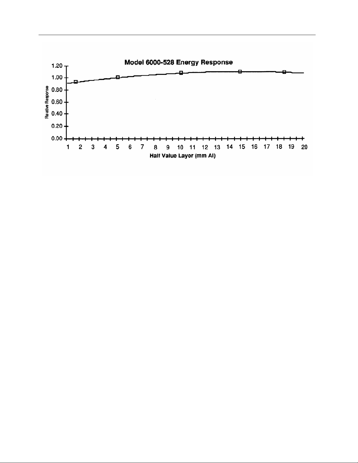
Figure 1-1. Model 6000-528 Energy Response
1.4 Procedures, Warnings and Cautions
The equipment described in this manual is intended to be used for the detection and measurement of
ionizing radiation. It should be used only by persons who have been trained in the proper interpretation of
its readings and the appropriate safety procedures to be followed in the presence of radiation.
Although the equipment described in this manual is designed and manufactured in compliance with all
applicable safety standards, certain hazards are inherent in the use of electronic and radiometric
equipment.
Warnings and Cautions are presented throughout this document to alert the user to potentially
hazardous situations. A Warning is a precautionary message preceding an operation that has the
potential to cause personal injury or death. A Caution is a precautionary message preceding an operation
that has the potential to cause permanent damage to the equipment and/or loss of data. Failure to comply
with Warnings and Cautions is at the user's own risk and is sufficient cause to terminate the warranty
agreement between Fluke Biomedical, Radiation Management Services and the customer.
Adequate warnings are included in this manual and on the product itself to cover hazards that may be
encountered in normal use and servicing of this equipment. No other procedures are warranted by Fluke
Biomedical. It shall be the owner's or user's responsibility to see to it that the procedures described here
are meticulously followed, and especially that Warnings and Cautions are heeded. Failure on the part of
the owner or user in any way to follow the prescribed procedures shall absolve Fluke Biomedical and its
agents from any resulting liability.
Indicated battery and other operational tests must be performed prior to each use to assure that the
instrument is functioning properly. If applicable, failure to conduct periodic performance tests in
accordance with ANSI N323-1978 (R1983) Radiation Protection Instrumentation Test and Calibration,
paragraphs 4.6 and 5.4, and to keep records thereof in accordance with paragraph 4.5 of the same
standard, could result in erroneous readings or potential danger. ANSI N323-1978 becomes, by this
reference, a part of this operating procedure.
1-2
Page 7

Introduction
Receiving Inspection
1.5 Receiving Inspection
Upon receipt of the unit:
1. Inspect the carton(s) and contents for damage. If damage is evident, file a claim with the carrier and
notify Fluke Biomedical at 440.248.9300.
2. Remove the contents from the packing material.
3. Verify that all items listed on the packing list have been received and are in good condition.
If any of the listed items are missing or damaged,
notify Fluke Biomedical at 440.248.9300.
NOTE
1.6 Storage
The storage requirements for this instrument are listed below.
1. The instrument should be stored in a cool, dry location.
2. If the instrument is taken from it's current location and is to be placed in a new location with a
different ambient temperature, allow the instrument to reach the new location's ambient temperature
before
applying power.
1
1-3
Page 8

Victoreen 6000-528
Operators Manual
(Blank Page)
Page 9

2.1 Installation
Installation
Installation
2
Section 2
Installation
Ensure all power is removed prior to installing the
Model 6000-528 Ion Chamber.
Installation of the Model 6000-528 External Ion Chamber consists of connecting the signal and high
voltage cables, and performing a calibration.
CAUTION
2.2 Electrical Interface
Final electrical interface connections between the Ion Chamber, and the host instrument are listed in
Table 2-1.
Table 2-1. Electrical Interface Connections
Connector Description
BNC Ion Chamber Output
HV (BIAS) Ion Chamber High Voltage
2.3 Setup
Because the Model 6000-528 External Ion Chamber may be used with NERO® 6000B, 6000M, 4000+, or
the 4000M+ please refer to the applicable instrument manual for instrument set up.
2-1
Page 10

Victoreen 6000-528
Operators Manual
(Blank Page)
Page 11

Operation
Theory of Operation
3
Section 3
Operation
3.1 Theory of Operation
An ionization chamber consists of a defined volume of air in which ions produced by radiation passing
through the chamber can be collected and measured. The Model 6000-528 is a parallel plate ion
chamber, consisting of a guarded center electrode placed between two outer plates, which also serve as
windows. A potential difference in the range of approximately 200 - 300 volts is placed across the plates
of the ion chamber. When ionizing radiation passes through the chamber, ion pairs are produced, each
pair consisting of one positive and one negative ion. Under the influence of the electric field produced by
the potential on the plates, the ions move toward their oppositely charged plate. Upon arrival, they are
neutralized by the free charges on the plates, taking an electron from the negative plate and adding an
electron to the positive plate. This causes a current to flow through the external electronics connected to
the plates, the magnitude of which is proportional to the rate of exposure to radiation.
The sensitivity of an ion chamber depends on the number of air molecules in the chamber; in fact these
quantities are directly proportional. The number of molecules is a function of volume, temperature, and
pressure. The volume of air in the chamber is fixed, but since it communicates with the atmosphere,
temperature and pressure will vary. A correction factor should be applied to the reading given by the ion
chamber, based on the ambient temperature and barometric pressure at the time the measurement is
made. For diagnostic x-ray use, this is usually unnecessary since the errors are on the order of 0.3% per
degree Celsius and 0.1% per mmHg. In any event, the correction factor is calculated by the following
expression:
cf = P
Where T is the temperature in degrees Celsius and P is the pressure in mmHg. T
temperature and pressure, respectively, at which the chamber was calibrated.
x T + 273.16
0
P T
+273.16
0
and P0 are the
0
3-1
Page 12

Victoreen 6000-528
Operators Manual
(Blank Page)
Page 13

Maintenance, Calibration, and Troubleshooting
Maintenance
Section 4
Maintenance, Calibration and Troubleshooting
4.1 Maintenance
The Model 6000-528 Ion Chamber requires no routine maintenance, other than routine inspection of the
chamber
for damage.
4.2 Calibration
The Model 6000-528 is not factory calibrated (although factory calibration is available). You may easily
calibrate the 6000-528 using the internal NERO® or 4000 chamber as a standard.
4
4.2.1 Calibration with a NERO 6000B or 6000M
1. Calibration will be performed on a standard radiographic x-ray machine. Set the machine to 100
kVp, 300 mA, 0.5 sec. Place the Model 6000-528 External Ion Chamber on the table and use a
distance of 40 inches. Collimate so as to uniformly irradiate the entire ion chamber.
2. Attach the Model 6000-528 External Ion Chamber to the NERO detector by connecting the BNC
connector to the appropriate jack on the back, then plug the banana plug into its mating jack.
Position the NERO detector such that no radiation will fall upon it. Connect the NERO detector to
the readout unit via the detector cable, plug into AC power and turn the unit on.
The NERO detector must be located out of the
radiation beam. The Model 6000-528 External Ion
Chamber is wired in parallel with the internal ion
chamber; therefore, any radiation falling on the
internal ion chamber will affect the reading. Shield if
necessary.
3. Verify the mR correction factor by pressing the key sequence, "F mR". The correction factor should
appear on the LCD. If it is not 1.000, enter 1 and press ENT.
4. To set up for an exposure, press “F-5". The display will clear as NERO measures electrometer drift
for twelve seconds. The NERO will beep and display "0.0 mR". Make an exposure, and record the
results. Press "NEXT" to clear the display and repeat. Make a total of five exposures in this manner.
All five should be within ± 3%. Compute an average and label it "Measured". Press "EXIT" to return
to the "Ready" condition.
5. Remove and disconnect the Model 6000-528 External Ion Chamber, and place the NERO detector
in the center of the beam. Raise the tube 2.25 inches to compensate for the height of the detector
box.
6. Make five exposures using the NERO detector in a similar manner as you did in step 4. Again all
five readings should be within ± 3%. Compute an average and label it "True".
NOTE
4-1
Page 14

Victoreen 6000-528
Operators Manual
7. Compute the correction factor according to the following formula:
cf = TRUE/MEASURED
This correction factor should be recorded and used when making the Model 6000-528 External Ion
Chamber dose measurements. To use, simply enter into the NERO as the mR correction factor by
pressing "F mR". The display will then read directly in mR. Remember to return the correction factor back
to 1.000 when not using the Model 6000-528 External Ion Chamber.
4.2.2 Calibration with a 4000M+
1. Calibration will be performed on a standard radiographic x-ray machine. Set the machine to 100
kVp, 300 mA, 0.5 sec. Place the Model 6000-528 External Ion Chamber on the table and use a
distance of 40 inches, Collimate so as to uniformly irradiate the entire ion chamber.
2. Attach the Model 6000-528 External Ion Chamber to the Model 4000M+ detector by connecting the
BNC connector to the appropriate jack on the back, then plug the banana plug into its mating jack.
Position the Model 4000M+ such that no radiation will fall upon it.
The Model 4000M+ must be located out of the
radiation beam. The Model 6000-528 External Ion
Chamber is wired in parallel with the internal ion
chamber; therefore, any radiation falling on the
internal ion chamber will affect the reading. Shield if
necessary.
3. To set up for an exposure, set the Radio/Fluoro switch to "Radio" and ALL/EXP to "EXP". The
Model 4000M+ will beep and display "0.0 mR", Make an exposure, and record the results. Press
"ROLL/RST" to clear the display and repeat. Make a total of five exposures in this manner. All five
should be within ± 3%. Compute an average and label it "Measured".
4. Remove and disconnect the Model 6000-528 External Ion Chamber, and place the Model 4000M+
detector in the center of the beam. Raise the tube 2.25 inches to compensate for the height of the
detector box.
5. Make five exposures using the Model 4000M+ detector in a similar manner as you did in step 3.
Again all give readings should be within 3%. Compute an average and label it "True".
6. Compute the correction factor according to the following formula: cf = TRUE/MEASURED
This correction factor should be recorded and used when making the Model 6000-528 External Ion
Chamber dose measurements. To use, simply multiply the exposure or exposure rate readings by cf, or if
you are using DXS, cf may be entered as the exposure correction factor.
NOTE
4.2.3 Determining Calibration Factor (cf) for Factory Calibrated Chambers
The following can be performed to determine the calibration factor:
1. Obtain the calibration results of your Model 6000-528 ion chamber, reported as R/nC. (Fluke
Biomedical can supply this if needed).
2. Locate "Charge Calibration" on the 6000 or 4000 series calibration sheet reported as nc/R.
3. Multiply the two numbers together to obtain cf.
4.2.4 Calibration with a Model 6000-530 Preamplifier
4-2
Page 15

Victoreen 6000-528
Operators Manual
The Fluke Biomedical Model 6000-530 preamplifier provides a means of matching your 6000-528
ionization chamber to a Model 6000B, 6000M, 4000M+, or 4000+ so that exposure and exposure rate
values may be read directly from the instrument display. The 6000-530 must first be adjusted to
accomplish this.
The following describes how to construct the calibration fixture, and how to obtain the value of chamber
sensitivity.
1. Turn on the host instrument and allow 3 to 5 minutes to warm-up. The preamplifier automatically
powers up when it senses high voltage from the host instrument.
2. Zero the host instrument, with nothing connected to the input, by selecting the fluoroscopic (rate)
mode and waiting until the display stabilizes.
NOTE
If the calibration fixture hasn't been constructed,
construct the fixture as shown in the schematic
below (Figure 4-1):
CAUTION
Ensure that the 9 V DC battery is installed with the
correct polarity when constructing the calibration
fixture.
Figure 4-1.
3. Connect one end of a coaxial cable to the BNC connector on the calibration fixture. Connect the
other end of the cable to the input of the host instrument.
4. Adjust the potentiometer on the calibration fixture until the instrument reads 1.00 R/min.
5. Disconnect the calibration fixture and make no further adjustments to the potentiometer. If the
potentiometer is moved, re-perform steps 4 and 5.
6. Turn off the host instrument and attach the preamplifier to the host input. Turn power on and allow
to warm up for five minutes.
NOTE
Do not adjust the CAL potentiometer located on the
preamplifier. Doing so will change the factory
calibration.
4-4
NOTE
Page 16

Victoreen 6000-528
Operators Manual
The ZERO adjust is a fine adjustment and requires
multiple turns on the potentiometer to change the
least
significant digit.
7. Zero the preamplifier, with nothing connected to the input, by adjusting the pot labeled ZERO.
8. Connect the calibration fixture to the input of the preamplifier.
Obtain the value of chamber sensitivity in dimensions of exposure per unit charge. Also, obtain the
charge calibration factor for the host instrument in dimensions of charge per displayed exposure
unit. Multiply these factors together to obtain a unitless correction factor as follows:
(Rm/nC) x C2 (nC/Rd) = F (Rm/Rd)
C
1
Where C
is the combined correction factor. The subscripts; m and d, attached to the Roentgen designation,
indicate measured and displayed values. Therefore, the final unitless correction factor, multiplied by
a displayed value yields the actual measured value.
9. Select the 30 cm
10. Adjust the 30 cm
appears on the display. The preamplifier is now calibrated for the specific chamber.
and C2 are the calibration factors for the chamber and the host instrument, respectively. F
1
3
position chamber volume, using the rotary switch.
3
, gain potentiometer on the preamplifier until the value of F, calculated previously,
4.3 Troubleshooting
Extreme care must be used when troubleshooting a
system that has power applied. All standard
troubleshooting precautions apply.
Once a problem has been located, remove all
power before continuing with the repair.
Personnel performing the troubleshooting must be
familiar with the operation of the system and the
location of each piece of equipment used.
WARNING
CAUTION
Troubleshooting consists of checking the wiring and verifying inputs/outputs are present on all
connectors, if a problem develops with the Ion Chamber, return the chamber to Fluke Biomedical.
NOTE
If a problem cannot be resolved by applying the
troubleshooting procedures described above,
contact Fluke Biomedical at 440.248.9300 for
assistance.
4-4
Page 17

(Blank Page)
Page 18

Fluke Biomedical
Radiation Management Services
6045 Cochran Road
Cleveland, Ohio 44139
440.498.2564
120 Andrews Road
Hicksville, New York 11801
516.870.0100
www.flukebiomedical.com/rms
 Loading...