

Page 1
576
Precision Infrared Thermometer
Users Manual
99 Washington Street
Melrose, MA 02176
Phone 781-665-1400
Toll Free 1-800-517-8431
Visit us at www.TestEquipmentDepot.com
March 2005
© 2005 Fluke Corporation. All rights reserved.
All product names are trademarks of their respective companies.
Page 2

576
LIMITED WARRANTY AND LIMITATION OF LIABILITY
This Fluke product will be free from defects in
material and workmanship for one year from the
date of purchase. This warranty does not cover
fuses, disposable batteries, or damage from
accident, neglect, misuse, alteration, contamination, or abnormal conditions of operation or
handling. Resellers are not authorized to extend
any other warranty on Fluke’s behalf. To obtain
service during the warranty period, contact your
nearest Fluke authorized service center to obtain
return authorization information, then send the
product to that Service Center with a description
of the problem.
THIS WARRANTY IS YOUR ONLY REMEDY. NO
OTHER WARRANTIES, SUCH AS FITNESS FOR
A PARTICULAR PURPOSE, ARE EXPRESSED
OR IMPLIED. FLUKE IS NOT LIABLE FOR ANY
SPECIAL, INDIRECT, INCIDENTAL OR CONSEQUENTIAL DAMAGES OR LOSSES, ARISING
FROM ANY CAUSE OR THEORY. Since some
states or countries do not allow the exclusion or
limitation of an implied warranty or of incidental
or consequential damages, this limitation of liability may not apply to you.
2
Page 3

Warning
Safety Information
A Warning identifies conditions and actions that pose hazards to the user. To avoid electrical shock or personal injury,
follow these guidelines:
• Do not point laser directly at eye or indirectly off
reflective surfaces.
• Before using the thermometer inspect the case. Do not
use the thermometer if it appears damaged. Look
for cracks or missing plastic.
• Replace the batteries as soon as the battery indicator
two or less segments.
• Do not use the thermometer if it operates abnormally.
Protection may be impaired. When in doubt, have the
thermometer serviced.
• Do not operate the thermometer around explosive gas,
vapor, or dust.
• Do not connect the optional external probe to live
electrical circuits.
• To avoid a burn hazard, remember that highly reflective
objects will result in lower than actual temperature
measurements.
• Do not use in a manner not specified by this manual or the
protection supplied by the equipment may be impaired.
Caution
To avoid damaging the thermometer or the equipment under
test protect them from the following:
• EMF (electro-magnetic fields) from arc welders,
induction heaters, etc.
• Static electricity
• Thermal shock (caused by large or abrupt
ambient temperature changes- allow 30 minutes
for thermometer to stabilize before use).
• Do not leave the thermometer on or near
objects of high temperature.
576
3
Page 4

576
Table of Contents
Introduction .......................................................... 5
Symbols and Safety Markings ............................. 6
Laser Warning and Serial Number Labels ............ 7
Delivery Content ................................................... 8
Batteries and Measurement ................................. 9
Using the Camera .................................................10
Field of View ......................................................... 12
Spot Size .............................................................. 13
Emissivity - Explanation ....................................... 14
Emissivity ..............................................................15
Emissivity - Unknown Value ................................. 16
Emissivity Table (Selected Values) ........................ 17
Hardware and Software Setup ............................. 18
Display .................................................................. 20
Data ...................................................................... 21
Setup .................................................................... 22
Mode ................................................................... 24
Mode - Thermocouple Settings ...........................26
DIP Switches ........................................................ 27
Troubleshooting .................................................... 28
Maintenance .........................................................30
CE Conformity ...................................................... 31
Specifications ....................................................... 32
Specifications of the Camera ............................... 33
4
Page 5

The Fluke Model 576 Infrared Thermometer (the
Introduction
thermometer) is for non-contact temperature
measurement. This thermometer determines
an object‘s surface temperature by measuring
the amount of infrared energy radiated by the
object‘s surface.
576
Test Equipment Depot - 800.517.8431 - 99 Washington Street Melrose, MA 02176
FAX 781.665.0780 - TestEquipmentDepot.com
Page 6
6
576
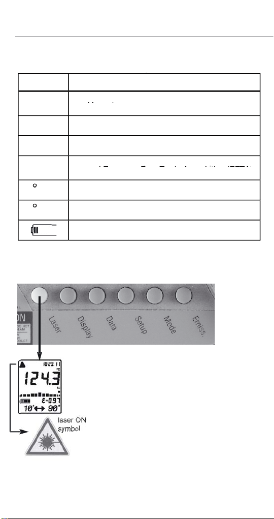
Symbol Explanation
Warning. Laser.
Symbols and Safety Markings
symbol
The laser sighting marks
the spot size that includes
the measured target.
To turn the laser On or Off,
when the trigger is pulled.
A laser symbol appears
when the laser is on. The
Page 7
7
576
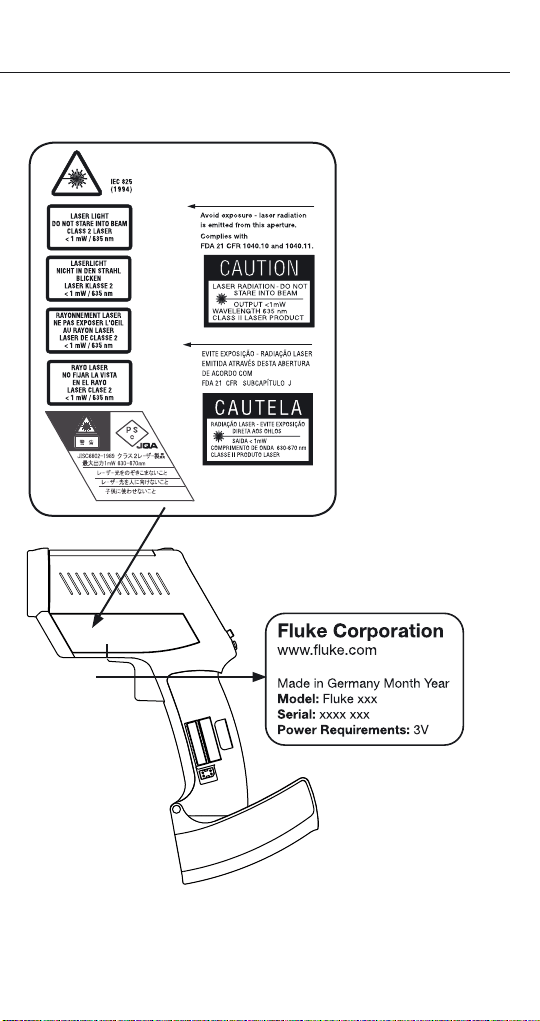
Laser Warning and Serial Number Labels
Page 8
8
576
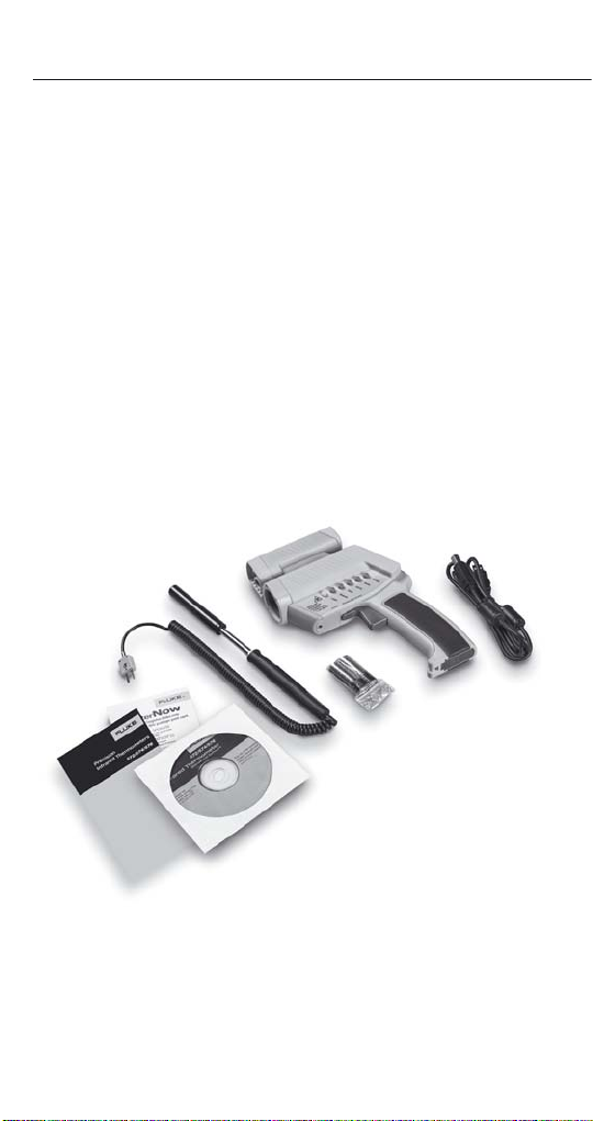
• The unit
• Getting Started
• Two AA batteries
• Manual on CD
• Thermocouple type K probe
• Windows-based software on CD
• USB cable
Delivery Content
Page 9
9
576
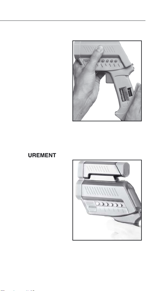
Batteries and Measurement
To open the battery
the handle
to release
the catch and pivot the
figure. Orient the batteries
To take a temperature
target. Pull the trigger (F).
The temperature of the
The temperature will
Page 10

576
Using the Camera
In addition to the thermometer functionality the
Model 576 comes with a digital built-in camera
to documentate the measured places. The
pictures include the measured values and
additional information. the additional information
is customizable via the IRGraph software.
How to use the camera
1. To switch on the unit, pull the trigger.
2. Press the “Enter” button to activate the
camera while the display is active.
3. First the word “LOG” flashes and then the
camera icon appears.
The unit is ready to use now. It is preset to
take 26 high-resolution (640x480 pixel)
pictures.
4. Pull the trigger and hold it. The laser circle
shows where you are measuring.
5. Aim at the target. Be sure that the laser
sighting is inside the target.
6. Gently release the trigger to record the
photo and the temperature. Successful
recording of picture and temperature is
indicated by two short beeps and a green
blinking LED above the display. The next
location will be shown on the display.
Caution:
If you hear a longer beep and the LED
above the display is shining red, look at the
display. If you see “Use Flash!” and a flash
symbol, repeat your last measurement.
A green LED above the camera symbol
Test Equipment Depot - 800.517.8431 - 99 Washington Street Melrose, MA 02176
FAX 781.665.0780 - TestEquipmentDepot.com
Page 11

signals: “Flash has charged”. The flash will
now fire automatically.
7. For the next measurement, repeat points
5 and 6.
8. Once you have taken all your photos,
connect the unit to the PC via USB.
See software and hardware set up on the next
two pages
Focusing the Camera
To get sharp and clear pictures simply turn the
focus ring depending on the distance of your
target.
.
576
Between
0.2 m
(8 in) and
0.3 m
(12 in.)
adjust the
lens to the
flower
symbol.
Between 0.25 m (10 in.) and 0.6
m (23 in.) adjust the lens in the
middle of both symbols.
The View Finder Guide
Rotate the cap to a horizon
tal position and look over it,
as shown below. The embossed triangle will show you
the approximate width of the
photo.
Between
0.5 m (19 in)
and infinity
adjust the
lens to the
mountain
symbol.
-
11
Page 12

576
Field of View
Make sure that the target is larger than the unit’s
spot size. The smaller the target, the closer you
should be to it.
12
Page 13

576
STANDARD MODEL
Optical Chart
3000
120
1.0
0
0
24
SPOT DIA. (IN)
SPOT DIA. (mm)
DISTANCE: SENSOR TO OBJECT (mm)
DISTANCE: SENSOR TO OBJECT (IN)
FOCUS POINT D:S = 60:1 FAR FIELD D:S = 35:1
0.76 IN @ 46 IN
19 mm @ 1150 mm
1500
2500
100
60
1.2
2.3
2.9
29.0
58.0
72.0
2000
44.0
1000
500
250
100
24
23
30
0.9
0.81
0.82
1.51
1.85
2.5
19.8
108
84
72
48
20
36
46
0.87
CLOSE FOCUS MODEL
Optical Chart
500
20
1
0
0
0.93
25
23
SPOT DIA. (IN)
SPOT DIA. (mm)
DISTANCE: SENSOR TO OBJECT (mm)
DISTANCE: SENSOR TO OBJECT (IN)
FOCUS POINT D:S = 50:1 FAR FIELD D:S = 12:1
0.24 IN @ 11.8 IN
6 mm @ 300 mm
Close Focus
6
0.62
15,5
150
2
0.9
22
50
4
0.75
18,7
100
7.9
9.8
200
250
0.49
0.37
12,3
9,2
40
1000
2.81
70
Spot Size
The measured spot size depends on the distance between the object you are measuring and
the infrared thermometer.
The relationship between distance and spot size
is 60:1(Standard Focus) or 50:1 (Close Focus) at
the focus point. The D:S in the far field (>33ft/
10m) is 35:1 (Standard) or 12:1 (Close Focus).
13
Page 14

14
576
Emissivity - Explanation
Transmitted energy
Target
The amount of infrared
temperature.
The emissivity depends on
the material and its surface
the emissivity value for
the type of material being
Page 15

576
Emissivity
To
ting.
will have a
flashes. Use the Up and Down keys
to adjust. Press ENTER (D) to acti-
Test Equipment Depot - 800.517.8431 - 99 Washington Street Melrose, MA 02176
FAX 781.665.0780 - TestEquipmentDepot.com
Page 16

16
576
Emissivity - Unknown Value
To
tip of the probe on the area to be measured.
W
which will be shown in the display. Press the
flashes. Use the arrow keys to change the
the probe’s reading.
Page 17

17
576
Emissivity Table (Selected Values)
Aluminum* 0.30
Asbesto 0.95
Asphalt 0.95
Water 0.93
Wood*** 0.94
Page 18

18
576
you install the software
you must connect the unit with the PC to
ware will be found. You have to install three
ter and the camera. You will be asked three times
to install a driver.
During the driver installation, a message
window could appear, indicating that a particular
with the installation.
The Windows Hardware Assistant will guide you
through the installation process. If you are asked
where to look for the drivers choose CD-ROM. In
Hardware and Software Setup
Page 19

For the software installation follow the
information on the screen.
Start the software with a double-click on the
IRGraph icon on the desktop.
The following screen appears
576
The complete description of the software features is in the help files of the software.
19
Page 20

576
Display
The last ten measurements are
the measured maximum and
the display interval of the bar
the total numbers of photos possi-
This sets up the BEGIN value for
the graphic display of the bar
the temperature as a picture.
This sets up the END value for the
Test Equipment Depot - 800.517.8431 - 99 Washington Street Melrose, MA 02176
FAX 781.665.0780 - TestEquipmentDepot.com
Page 21

21
576
Data
temperature values and photos.
The configuration of the logger file
ture value
stored at this
tion.
temperature
v
tion. Nothing
stored.
this logger
Page 22

22
576
Setup
This feature deletes all
this function. The pictures
The configuration of the alarm values can
Page 23

23
576
This function is used with a selected
temperature values for several units to be
temperature tolerance difference between
temperature range.
ys.Then press ENTER for each time
time is stored within the data logger.
ys.Then press ENTER for each date seg-
Page 24

24
576
Mode
To
To
the emissivity settings by using
the Emiss. button, when not in
To
v
Page 25

25
576
the trigger is pulled or locked on.
The real time temperature is
temperature is shown in the lower
Test Equipment Depot - 800.517.8431 - 99 Washington Street Melrose, MA 02176
FAX 781.665.0780 - TestEquipmentDepot.com
Page 26

26
576
Mode - Thermocouple Settings
A
s
TC-J/TC-K
Time/Date
TC - thermocouple
Thermocouple type J
Thermocouple type K
The input is located at the bot-
tom of the handle behind the
tton
Page 27

27
576
DIP Switches
the DIP switches. These switches are located in
the Battery compartement of the unit.
TC-J/TC-K
Time/Date
tinuous measuring mode
degrees Celsius and
signals On or Off
the display On or Off
default, if On
ttons are blocked
when temperature val-
A
All = every photo is taken
with flash
Time or Date will be
displayed
Thermocouple settings -
corresponding
chapter
Page 28

28
576
Troubleshooting
Symptom
to the PC the PC to fix it
too long to
work
Ambient above 45°C (113°F) Operate unit in
45°C (113°F)
ambient or below
from the PC
after removing old ones Change batteries within
two minutes of
file does not match in the PC software do not the current data to a
the correct *.lgg file,
and redownload the
the display shines to indicate a problem, check
y
Page 29

29
576
Symptom
available light. “Auto/All”set to “All”
to PC software or correct com port in use. or disconnect other
when software started com port
window window. Choose
after a photo and to record photo and data. of the data and
to Setup in the unit,
Page 30

30
576
Maintenance
Wipe the surface with a
with water or a water
use sol-
vents to clean the
To clean the exterior
water or a mild commer-
Test Equipment Depot - 800.517.8431 - 99 Washington Street Melrose, MA 02176
FAX 781.665.0780 - TestEquipmentDepot.com
Page 31

This instrument conforms to the following
CE Conformity
standards:
EMC: - EN 61326-1:1997+A1:1998+A2:2001
Safety: - EN 61010-1:2001
- EN 60825-1:2001
This product herewith complies with the
requirements of the EMC Directive
89/336/EEC and the Low Voltage
Directive 73/23/EEC.
This instrument conforms to the Standards
of the European Community.
Certification
576
The temperature sources used to calibrate this
instrument are traceable to the U.S. National
Institute of Standards and Technology (NIST)
and the Deutscher Kalibrierdienst (DKD).
Calibration certificates are available as an option.
31
Page 32

576
Specifications
Temp. Range - 30 to 900°C (- 25 to 1600°F)
Display Resolution 0.1°C (0.2°F)
Accuracy (Infrared)
at 25°C (77°F)
ambient temperature
Ambient Derating < 0.05K/K or < 0.05%/K,
Optical Resolution
(Standard Focus)
Optical Resolution
(Close Focus)
Accuracy
(Thermocouple K & J)
Accuracy (Thermistor) -30 to 0°C (-22 to 32°F) ± 0.6K
Repeatability
(Infrared)
Response Time (95%) 250 mSec
Hot Spot Detection (30%) 85 mSec
Spectral Range 8 to 14 µm
Ambient Operating Range 0 to 50°C (32 to 122°F)
Storage Temperature -20 to 50°C (-4 to 122°F) without
Relative Humidity 10 to 90% at 30°C (86°F),
Analog Output
(optional cable needed)
Digital Output USB 1.1
Power 2 x 1.5 V Alkaline Type AA
Dimensions 240 x 170 x 50 mm
Tripod Mount 1/4”-20 UNC
± 0.75% of reading or
± 1 K (± 1.5°F), whichever is greater ± 2°C (± 4°F) for targets below
-5°C (23°F)
whichever is greater at
+ 25°C (77°F) ± 25° (± 45°F)
60:1 (19mm spot size at 1.15 m)
(0.75in. spot size at 3.8 feet)
50:1 ( 6mm spot size at 0.3 m)
(0.24in. spot size at 0.98 feet)
± 2°C or ± 0.75%,
whichever is greater
0 to 70°C (32 to 158°F) ± 0.4K
70 to 100°C (158 to 212°F) ±1K
100 to 120°C (212 to 248°F) ±1.5K
± 0.5% of reading or ± 0.5°C (1°F),
whichever is greater, ± 1°C (± 2°F)
for targets below -5°C (23°F)
batteries
non condensing
1 mV/°C (°F)
(7.9 x 6.7 x 2 inches)
32
Page 33

576
Specifications of the Camera
Maximum Picture Number
640x480 Pixels (VGA)
26
Maximum Picture Number
320x240 Pixels (1/4 VGA)
100
Recharge Time for Flash approx. 5 sec
Useful Flash Range:
Standard Focus
Close Focus
0.5 to 2 m (19 to 79 in.)
0.2 to 1 m ( 8 to 40 in)
Camera Lens 6 mm (app. equal to 42 mm on a
35 mm camera)
Focal Points 200 mm (8 in.)(Close-up)
Infinity (Far Distance)
Light Sensitivity 6 lux
Shutter Speed variable, max. 1/15 sec
Data Interface USB 1.1
Image File Format JPG
Back to the Fluke 576 Product Info Page
Visit us at www.TestEquipmentDepot.com
Test Equipment Depot - 800.517.8431 - 99 Washington Street Melrose, MA 02176
FAX 781.665.0780 - TestEquipmentDepot.com
33
 Loading...