


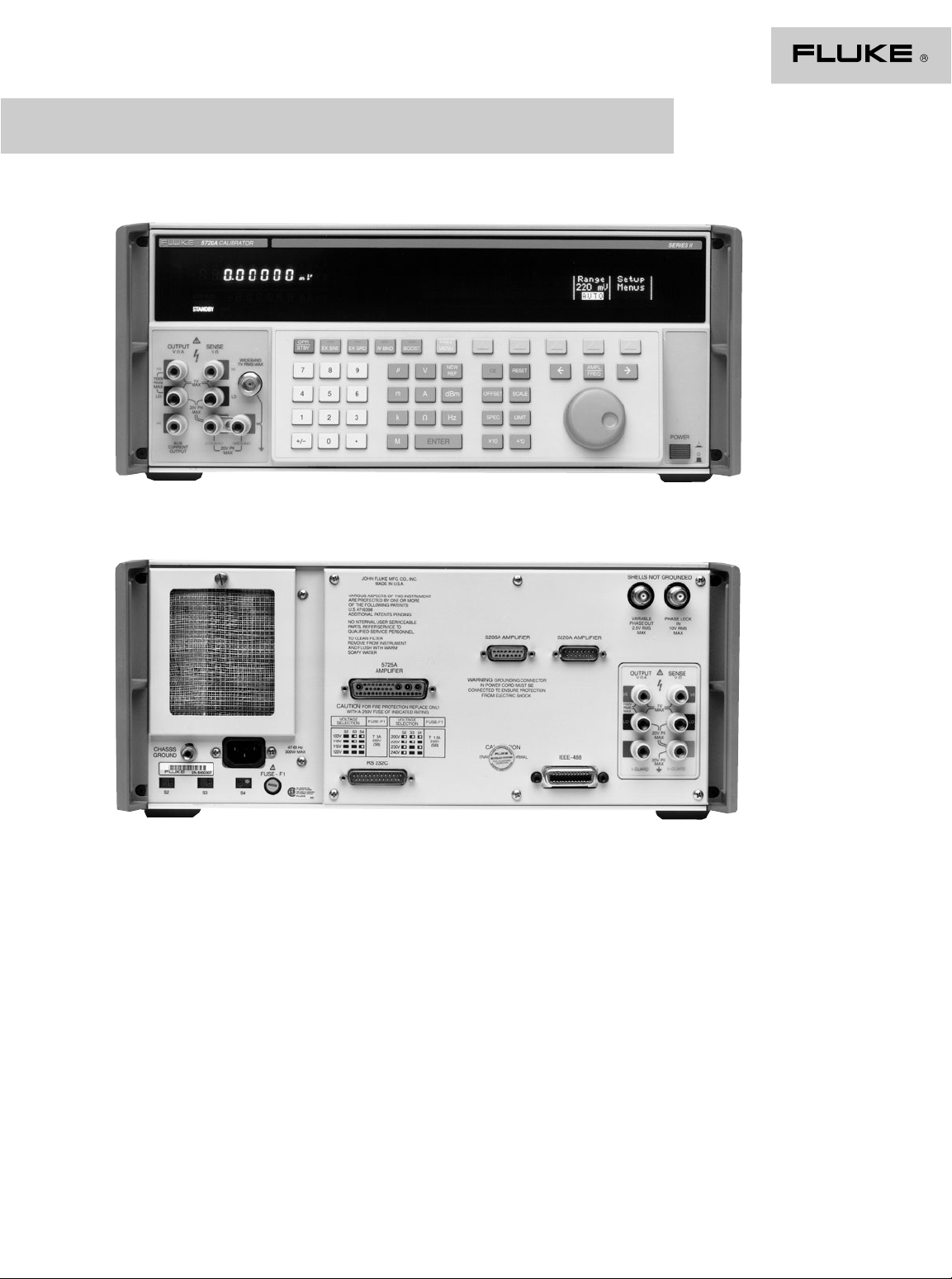
The 5700A /5720A
High Performance
Multifunction Calibrators
Extended Specifications
November 2001

DC Voltage Specifications
5720A Calibrator
Absolute uncertainty ± 5 °C from calibration temperature Relative uncertainty ± 1 °C
Range Resolution 24 Hours 90 Days 180 Days 1 Year 24 Hours 90 Days
± (ppm output + µV)
95 % Confidence Level
220 mV 10 nV 4 + 0.4 6 + 0.4 6.5 + .04 7.5 + 0.4 1.6 + 0.4 2 + 0.4
2.2 V 100 nV 3 + 0.7 3.5 + 0.7 4 + 0.7 5 + 0.7 1.6 + 0.7 2 + 0.7
11 V 1 µV2+2.5 2.5 + 2.5 3 + 2.5 3.5 + 2.5 0.8 + 2.5 1.2 + 2.5
22 V 1 µV2+42.5 + 4 3 + 4 3.5 + 4 0.8 + 4 1.2 + 4
220 V 10 µV3+403.5 + 40 4 +40 5+40 1.6+40 2+40
1100 V 100 µV4+400 4.5 + 400 6 + 400 6.5 + 400 2 + 400 2.4 + 400
99 % Confidence Level
220 mV 10 nV 5 + 0.5 7 + 0.5 8 + 0.5 9 + 0.5 2 + 0.4 2.5 + 0.4
2.2 V 100 nV 3.5 + 0.8 4 + 0.8 6 + 0.8 6 + 0.8 2 + 0.8 2.5 + 0.8
11 V 1 µV 2.5 + 3 3 + 3 4 +3 4+3 1+3 1.5+3
22 V 1 µV 2.5 + 5 3 + 5 4 +5 4+5 1+5 1.5+5
220 V 10 µV 3.5 + 50 4 +50 6+50 6+50 2+50 2.5+50
1100V 100 µV5+500 6 + 500 7 + 500 8 + 500 2.5 + 400 3 + 400
5700A Series II Calibrator
Absolute uncertainty ± 5 °C from calibration temperature Relative uncertainty ± 1 °C
Range Resolution 24 Hours 90 Days 180 Days 1 Year 24 Hours 90 Days
± (ppm output + µV)
95 % Confidence Level
220 mV 10 nV 5.5 + 0.6 6 + 0.6 7 + 0.6 8 + 0.6 2 + 0.4 3.5 + 0.4
2.2 V 100 nV 3.5 + 1 5 + 1 6 + 1 7 + 1 2 + 1 3.5 + 1
11 V 1 µV3+34+3.5 6 + 3.5 7 + 3.5 1.2 + 3 3 + 3.5
22 V 1 µV3+5.5 4 + 6.5 6 + 6.5 7 + 6.5 1.2 + 6 3 + 7
220 V 10 µV4+805+80 7+80 8+80 2+80 3.5+80
1100 V 100 µV6+500 7 + 500 8 + 500 9 + 500 2.4 + 500 4 + 500
99 % Confidence Level
220 mV 10 nV 6.5 + 0.75 7 + 0.75 8 + 0.75 9 + 0.8 2.5 + 0.5 4 + 0.5
2.2 V 100 nV 3.5 + 1.2 6 + 1.2 7 + 1.2 8 + 1.2 2.5 + 1.2 4 + 1.2
11 V 1 µV 3.5 + 3 5 + 4 7 +4 8+4 1.5+3 3.5+4
22 V 1 µV 3.5 + 6 5 + 8 7 +8 8+8 1.5+6 3.5+8
220 V 10 µV5+1006+1008+100 9+100 2.5+100 4+100
1100 V 100 µV7+6008+60010+600 11+600 3+600 4.5+600
For field strengths > 1 V/m but ≤ 3 V/m, add 0.01 % of range.
2 Fluke Corporation 5700A/5720A High Performance Multifunction Calibrators Extended Specifications

5720A/5700A Series II secondary performance specifications and operating characteristics
1
Stability
Range 24 Hours 10 °C-40 °C and 40 °C-50 °C ± 1 °C pk-pk rms
220 mV 0.3 + 0.3 0.4 + 0.1 1.5 + 0.5 1 + 0.2 0.15 + .1 5
2.2 V 0.3 + 1 0.3 + 0.1 1.5 + 2 1 + 0.6 0.15 + .4 15
11 V 0.3 + 2.5 0.15 + 0.2 1 + 1.5 0.3 + 2 0.15 + 2 50
22 V 0.4 + 5 0.2 + 0.4 1.5 + 3 0.3 + 4 0.15 + 4 50
220 V 0.5 + 40 0.3 + 5 1.5 + 40 1 + 40 0.15 + 60 150
1100 V 0.5 + 200 0.5 + 10 3 + 200 1 + 200 0.15 + 300 500
1
Stability specifications are included in the absolute uncertainty values in the primary specification tables.
2
Temperature coefficient is an adder to uncertainty specifications that does not apply unless operating more
than ± 5 °C from calibration temperature.
± 1 °C0 °C-10 °C Linearity 0.1-10 Hz 10 Hz-10 kHz
± (ppm output + µV) ± (ppm output + µV)/°C ± (ppm output + µV) µV
Temperature coefficient
2
Bandwidth Bandwidth
Noise
Minimum output: 0 V for all ranges, except 100 V
for 1100 V range
Maximum load: 50 mA for 2.2 V through 220 V
ranges; 20 mA for 1100 V range; 50 Ω output
impedance on 220 mV range; all ranges < 1000 pF,
> 25 Ω
Load regulation: < (0.2 ppm of output + 0.1 ppm of
range), full load to no load
Line regulation: < 0.1 ppm change, ± 10 % of
selected nominal line
Settling time: 3 seconds to full uncertainty; + 1
second for range or polarity change; + 1 second for
1100 V range
Overshoot: < 5 %
Common mode rejection: 140 dB, DC to 400 Hz
Remote sensing: Available 0 V to ± 1100 V, on 2.2 V
through 1100 V ranges
5700A/5720A High Performance Multifunction Calibrators Extended Specifications Fluke Corporation 3

AC Voltage Specifications
5720A Calibrator
95 % Confidence Level
Absolute uncertainty ± 5 °C from calibration temperature Relative uncertainty ± 1 °C
Range Resolution Frequency (Hz) 24 Hours 90 Days 180 Days 1 Year 24 Hours 90 Days
2.2 mV 1 nV 10 - 20 200 + 4 220 + 4 230 + 4 240 + 4 200 + 4 220 + 4
22 mV 10 nV 10 - 20 200 + 4 220 + 4 230 + 4 240 + 4 200 + 4 220 + 4
220 mV 100 nV 10 - 20 200 + 12 220 + 12 230 + 12 240 + 12 200 + 12 220 + 12
2.2 V 1 µV10-20200 + 40 220 + 40 230 + 40 240 + 40 200 + 40 220 + 40
22 V 10 µV10-20200 + 400 220 + 400 230 + 400 240 + 400 200 + 400 220 + 400
2
220 V
1100 V 1 mV 15 - 50
5725A Amplifier
1100 V 1 mV 40 - 1 k 75 + 4 80+4 85+4 90+450+455+4
750 V 1 mV 30 k - 50 k 230 + 11 360 + 11 440 + 11 600 +11 160+11 320+11
1
Maximum output 250 V from 15-50 Hz2See Volt-Hertz Capability on page 9
4 Fluke Corporation 5700A/5720A High Performance Multifunction Calibrators Extended Specifications
100 µV10-20200 + 4 220 + 4 230 + 4 240 + 4 200 + 4 220 + 4
20 - 40 80 + 4 85 + 4 87 + 490+480+485+4
40 - 20 k 70 + 4 75 + 4 77+4 80+4 50+5 55+4
20 k - 50 k 170 + 4 180 + 4 190 + 4 200 + 4 70 +5 80+4
50 k - 100 k 400 + 5 460 + 5 480 + 5 500 + 5 160 + 5 180 + 5
100 k - 300 k 300 + 10 900 + 10 1000 + 10 1050 + 10 280 + 10 320 + 10
300 k - 500 k 1100 + 20 1200 + 20 1300 + 20 1400 + 20 650 + 20 800 + 20
500 k - 1 M 2400 + 20 2500 + 20 2600 + 20 2700 + 20 2100 + 20 2400 + 20
20 - 40 80 + 7 85 + 7 87 + 790+780+785+7
40 - 20 k 70 + 7 75 + 7 77+7 80+7 50+7 55+7
20 k - 50 k 170 + 7 180 + 7 190 + 7 200 + 7 70 +7 80+7
50 k - 100 k 400 + 17 420 + 17 440 +17 460+17 160+17 180+17
100 k - 300 k 700 + 20 750 + 20 800 + 20 900 + 20 280 + 20 320 + 20
300 k - 500 k 1100 + 25 1200 + 25 1300 + 25 1400 + 25 650 + 25 800 + 25
500 k - 1 M 2400 + 45 2500 + 45 2600 + 45 2700 + 45 2100 + 45 2400 + 45
20 - 40 75 + 15 80 + 15 85 + 15 9 0 + 15 75 + 15 8 0 + 15
40 - 20 k 37 + 8 40 + 8 42+8 45+8 25+8 35+8
20 k - 50 k 65 + 10 70 + 10 73 + 10 75 + 10 55 + 10 60 + 10
50 k - 100 k 100 + 30 105 + 30 107 + 30 110 + 300 80 + 30 85 + 30
100 k - 300 k 300 + 80 340 + 80 380 + 80 420 + 80 230 + 80 250 + 80
300 k - 500 k 800 + 200 900 + 200 950 + 200 1000 + 200 700 + 200 800 + 200
500 k - 1 M 1300 + 300 1500 + 300 1600 + 300 1700 + 300 1000 + 300 1100 + 300
20 - 40 75 + 150 80 + 150 8 5 + 150 9 0 + 150 75 + 15 0 8 0 + 150
40 - 20 k 37 + 50 40 + 50 42 + 50 45 + 50 25 + 50 35 + 50
20 k - 50 k 65 + 100 70 + 100 73 + 100 75 + 10 0 55 + 10 0 6 0 + 100
50 k - 100 k 90 + 200 95 + 200 97 + 200 100 + 200 80 + 200 85 + 200
100 k - 300 k 250 + 600 260 + 600 270 + 600 275 + 600 250 + 600 270 + 600
300 k - 500 k 800 + 2000 900 + 2000 900 + 2000 1000 + 2000 700 + 2000 800 + 2000
500 k - 1 M 1200 + 3200 1300 + 3200 1400 + 3200 1500 + 3200 1100 + 3200 1200 + 3200
20 - 40 75 + 1.5 80 + 1.5 85 + 1. 5 9 0 + 1. 5 7 5 + 1.5 80 + 1. 5
40 - 20 k 45 + 0.6 47 + 0.6 50 + 0.6 52 + 0.6 35 + 0.6 40 + 0.6
20 k - 50 k 70 + 1 75 + 1 77+1 80+1 60+1 65+1
50 k - 100 k 120 + 2.5 130 + 2.5 140 + 2.5 150 + 2.5 110 + 2.5 120 + 2.5
100 k - 300 k 700 + 16 800 + 16 850 + 16 900 + 16 500 + 16 600 + 16
300 k - 500 k 4000 + 40 4200 + 40 4300 + 40 4400 + 40 3600 + 40 3800 + 40
500 k - 1 M 6000 + 80 7000 + 80 7500 + 80 8000 + 80 6500 + 80 7000 + 80
20 k - 30 k 230 + 11 360 + 11 440 +11 600+11 160+11 320+11
50 k - 100 k 600 + 45 1300 + 45 1600 + 45 2300 + 45 380 + 45 1200 + 45
1
50 - 1 k 55 + 3.5 60 + 3.5 65 + 3.5 70 + 3.5 40 + 3.5 45 + 3.5
1 k - 20 k 105 + 6 125 + 6 135 + 6 165 + 6 85 + 6 105 + 6
240 + 16 260 +16 280+16 300+16 240+16 260+16
± (ppm output + µV)
± (ppm output + mV)

5720A Calibrator
99 % Confidence Level
Absolute uncertainty ± 5 °C from calibration temperature Relative uncertainty ± 1 °C
Range Resolution Frequency (Hz) 24 Hours 90 Days 180 Days 1 Year 24 Hours 90 Days
± (ppm output + µV)
2.2 mV 1 nV 10 - 20 250 + 5 270 + 5 290 + 5 300 + 5 250 + 5 270 + 5
20 - 40 100 + 5 105+5 110+5 115+5 100+5 105+5
40 - 20 k 85 + 5 90 + 5 95+5 100+5 60+5 65+5
20 k - 50 k 220 + 5 230 + 5 240 + 5 250 + 5 85 + 5 95 + 5
50 k - 100 k 500 + 6 540 + 6 570 + 6 600 + 6 200 + 6 220 + 6
100 k - 300 k 1000 + 12 1200 + 12 1250 + 12 1300 + 12 350 + 12 400 + 12
300 k - 500 k 1400 + 25 1500 + 25 1600 + 25 1700 + 25 800 + 25 1000 + 25
500 k - 1 M 2900 + 25 3100 + 25 3250 + 25 3400 + 25 2700 + 25 3000 + 25
22 mV 10 nV 10 - 20 250 + 5 270 + 5 290 + 5 300 + 5 250 + 5 270 + 5
20 - 40 100 + 5 105+5 110+5 115+5 100+5 105+5
40 - 20 k 85 + 5 90 + 5 95+5 100+5 60+5 65+5
20 k - 50 k 220 + 5 230 + 5 240 + 5 250 + 5 85 + 5 95 + 5
50 k - 100 k 500 + 6 540 + 6 570 + 6 600 + 6 200 + 6 220 + 6
100 k - 300 k 1000 + 12 1200 + 12 1250 + 12 1300 + 12 350 + 12 400 + 12
300 k - 500 k 1400 + 25 1500 + 25 1600 + 25 1700 + 25 800 + 25 1000 + 25
500 k - 1 M 2900 + 25 3100 + 25 3250 + 25 3400 + 25 2700 + 25 3000 + 25
220 mV 100 nV 10 - 20 250 + 15 270 + 15 290 + 15 300 + 15 250 + 15 270 + 15
20 - 40 100 + 8 105+8 110+8 115+8 100+8 105+8
40 - 20 k 85 + 8 90 + 8 95+8 100+8 60+8 65+8
20 k - 50 k 220 + 8 230 + 8 240 + 8 250 + 8 85 + 8 95 + 8
50 k - 100 k 500 + 20 540 + 20 570 + 20 600 + 20 200 + 20 220 + 20
100 k - 300 k 850 + 25 900 + 25 1000 + 25 1100 + 25 350 + 25 400 + 25
300k - 500 k 1400 + 30 1500 + 30 1600 + 30 1700 + 30 800 + 30 1000 + 30
500k - 1 M 2700 + 60 2900 + 60 3100 + 60 3300 + 60 2600 + 60 2800 + 60
2.2 V 1 µV10-20250 + 50 270 + 50 290 + 50 300 + 50 250 + 50 270 + 50
20 - 40 95 + 20 100 + 20 105 + 20 110 + 20 95 + 20 100 + 20
40 - 20 k 45 + 10 47 + 10 50 + 10 52 + 10 30 + 10 40 + 10
20 k - 50 k 80 + 12 85 + 12 87 + 12 90 + 12 70 + 12 75 + 12
50 k - 100 k 120 + 40 125 + 40 127 + 40 130 + 40 100 + 40 105 + 40
100 k - 300 k 380 + 100 420 + 100 460 + 100 500 + 100 270 + 100 290 + 100
300 k - 500 k 1000 + 250 1100 + 250 1150 + 250 1200 + 250 900 + 250 1000 + 250
500 k - 1 M 1600 + 400 1800 + 400 1900 + 400 2000 + 400 1200 + 400 1300 + 400
22 V 10 µV10-20250 + 500 270 + 500 290 + 500 300 + 500 250 + 500 270 + 500
20 - 40 95 + 200 100 + 200 105 + 200 110 + 200 95 + 200 100 + 200
40 - 20 k 45 + 70 47 + 70 50 + 70 52 + 70 30 + 70 40 + 70
20 k - 50 k 80 + 120 85 + 120 87 + 120 9 0 + 120 70 + 12 0 75 + 12 0
50 k - 100 k 110 + 250 115 + 250 117 + 250 120 + 250 100 + 250 105 + 250
100 k - 300 k 300 + 800 310 + 800 320 + 800 325 + 800 270 + 800 290 + 800
300 k - 500 k 1000 + 2500 1100 + 2500 1150 + 2500 1200 + 2500 900 + 2500 1000 + 2500
500 k - 1 M 1500 + 4000 1600 + 4000 1700 + 4000 1800 + 4000 1300 + 4000 1400 + 4000
± (ppm output + mV)
2
220 V
1100 V 1 mV 15 - 50
5725A Amplifier
1100 V 1 mV 40 - 1 k 75 + 4 80+4 85+4 90+450+455+4
750 V 1 mV 30 k - 50 k 230 + 11 360 + 11 440 + 11 600 +11 160+11 320+11
1
Maximum output 250 V from 15-50 Hz2See Volt-Hertz Capability on page 9
100 µV10-20250 + 5 270 + 5 290 + 5 300 + 5 250 + 5 270 + 5
20 - 40 95 + 2 100 + 2 105 + 2110+2 95+2 100+2
40 - 20 k 57 + 0.7 60 + 0.7 62 + 0.7 65 + 0.7 45 + 0.7 50 + 0.7
20 k - 50 k 90 + 1.2 95 + 1.2 97 + 1.2 100 + 1.2 75 + 1.2 80 + 1.2
50 k - 100 k 160 + 3 170 + 3 175 + 3 180 + 3 140 + 3 150 + 3
100 k - 300 k 900 + 20 1000 + 20 1050 + 20 1100 + 20 600 + 20 700 + 20
300 k - 500 k 5000 + 50 5200 + 50 5300 + 50 5400 + 50 4500 + 50 4700 + 50
500 k - 1 M 8000 + 100 9000 + 100 9500 + 100 10000 + 100 8000 + 100 8500 + 100
1
300 + 20 320 + 20 340 + 20 360 + 20 300 + 20 320 + 20
50 - 1 k 70 + 4 75 + 4 80+4 85+450+455+4
1 k - 20 k 105 + 6 125 + 6 135 + 6 165 + 6 85 + 6 105 + 6
20 k - 30 k 230 + 11 360 + 11 440 +11 600+11 160+11 320+11
50 k - 100 k 600 + 45 1300 + 45 1600 + 45 2300 + 45 380 + 45 1200 + 45
5700A/5720A High Performance Multifunction Calibrators Extended Specifications Fluke Corporation 5

AC Voltage Specifications
5700A Series II Calibrator
95 % Confidence Level
Absolute uncertainty ± 5 °C from calibration temperature Relative uncertainty ± 1 °C
Range Resolution Frequency (Hz) 24 Hours 90 Days 180 Days 1 Year 24 Hours 90 Days
2.2 mV 1 nV 10 - 20 400 + 4.5 500 + 4.5 530 + 4.5 550 + 4.5 400 + 4.5 500 + 4.5
22 mV 10 nV 10 - 20 400 + 5 500 + 5 530 + 5 550 + 5 400 + 5 500 + 5
220 mV 100 nV 10 - 20 400 + 13 500 + 13 530 + 13 550 + 13 400 + 13 500 + 13
2.2 V 1 µV10-20400 + 80 450 + 80 480 + 80 500 + 80 400 + 80 450 + 80
22 V 10 µV10-20400 + 800 450 + 800 480 + 800 500 + 800 400 + 800 450 + 800
2
220 V
1100 V 1 mV 15 - 50
5725A Amplifier
1100 V 1 mV 40 - 1 k 75 + 4 80+4 85+4 90+450+455+4
750 V 1 mV 30 k - 50 k 230 + 11 360 + 11 440 + 11 600 +11 160+11 320+11
1
Maximum output 250 V from 15-50 Hz2See Volt-Hertz Capability on page 9
6 Fluke Corporation 5700A/5720A High Performance Multifunction Calibrators Extended Specifications
100 µV10-20400 + 8 450 + 8 480 + 8 500 + 8 400 + 8 450 + 8
20 - 40 170 + 4.5 190 + 4.5 200 + 4.5 210 + 4.5 170 + 4.5 190 + 4.5
40 - 20 k 85 + 4.5 95 + 4.5 100 + 4.5 105 + 4.5 55 + 4.5 60 + 4.5
20 k - 50 k 300 + 4.5 330 + 4.5 350 + 4.5 370 + 4.5 90 + 4.5 100 + 4.5
50 k - 100 k 700 + 7 750 + 7800+7850 + 7 210 + 7 230 + 7
100 k - 300 k 900 + 13 1000 + 13 1050 + 13 1100 + 13 380 + 13 420 + 13
300 k - 500 k 1300 + 25 1500 + 25 1600 + 25 1700 + 25 900 + 25 1000 + 25
500 k - 1 M 2800 + 25 3100 + 25 3300 + 25 3400 + 25 2900 + 25 3200 + 25
20 - 40 170 + 5 190 + 5 200 +5 210+5 170+5 190+5
40 - 20 k 85 + 5 95 + 5 100 +5 105+5 55+5 60+5
20 k - 50 k 300 + 5 330 + 5 350 + 5 370 + 5 90 + 5 100 + 5
50 k - 100 k 700 + 7 750 + 7800+7850 + 7 210 + 7 230 + 7
100 k - 300 k 900 + 12 1000 + 12 1050 + 12 1100 + 12 380 + 12 420 + 12
300 k - 500 k 1300 + 25 1500 + 25 1600 + 25 1700 + 25 900 + 25 1000 + 25
500 k - 1 M 2800 + 25 3100 + 25 3300 + 25 3400 + 25 2900 + 25 3200 + 25
20 - 40 170 + 8 190 + 8 200 +8 210+8 170+8 190+8
40 - 20 k 85 + 8 95 + 8 100 +8 105+8 55+8 60+8
20 k - 50 k 250 + 8 280 + 8 300 + 8 320 + 8 90 + 8 100 + 8
50 k - 100 k 700 + 25 750 + 25 800 +25 850+25 210+25 230+25
100 k - 300 k 900 + 25 1000 + 25 1050 + 25 1100 + 25 380 + 25 420 + 25
300 k - 500 k 1300 + 35 1500 + 35 1600 + 35 1700 + 35 900 + 35 1000 + 35
500 k - 1 M 2800 + 80 3100 + 80 3300 + 80 3400 + 80 2900 + 80 3200 + 80
20 - 40 130 + 25 140 + 25 150 + 25 160 + 25 130 + 25 140 + 25
40 - 20 k 60 + 6 65 + 6 70+6 75+6 35+6 40+6
20 k - 50 k 105 + 16 110 + 16 115 +16 120+16 85+16 95+16
50 k - 100 k 190 + 70 210 + 70 230 +70 250+70 170+70 190+70
100 k - 300 k 350 + 130 390 + 130 420 + 130 430 + 130 340 + 130 380 + 130
300 k - 500 k 850 + 350 950 + 350 1000 + 350 1050 + 350 850 + 350 950 + 350
500 k - 1 M 1700 + 850 1900 + 850 2100 + 850 2200 + 850 1700 + 850 1900 + 850
20 - 40 130 + 250 140 + 250 150 + 250 160 + 250 130 + 250 140 + 250
40 - 20 k 60 + 60 65 + 60 70 + 60 75 + 60 35 + 60 40 + 60
20 k - 50 k 105 + 160 110 + 160 115 +160 120+160 85+160 95+160
50 k - 100 k 190 + 350 210 + 350 230 + 350 250 + 350 170 + 350 190 + 350
100 k - 300 k 400 + 1500 450 + 1500 470 + 1500 500 + 1500 400 + 1500 450 + 1500
300 k - 500 k 1050 + 4300 1150 + 4300 1200 + 4300 1250 + 4300 1000 + 4300 1100 + 4300
500 k - 1 M 2300 + 8500 2500 + 8500 2600 + 8500 2700 + 8500 2200 + 8500 2400 + 8500
20 - 40 130 + 2.5 140 + 2.5 150 + 2.5 160 + 2.5 130 + 2.5 140 + 2.5
40 - 20 k 65 + 0.8 70 + 0.8 75 + 0.8 80 + 0.8 40 + 0.8 45 + 0.8
20 k - 50 k 170 + 3.5 190 + 3.5 210 + 3.5 220 + 3.5 85 + 3.5 95 + 3.5
50 k - 100 k 400 + 8 450 + 8 480 + 8 500 + 8 270 + 8 300 + 8
100 k - 300 k 1300 + 90 1400 + 90 1450 + 90 1500 + 90 1200 + 90 1300 + 90
300 k - 500 k 4300 + 90 4500 + 90 4600 + 90 4700 + 90 4200 + 90 4500 + 90
500 k - 1 M 10500 + 190 11000 + 190 11300 + 190 11500 + 190 10500 + 190 11000 + 190
20 k - 30 k 230 + 11 360 + 11 440 +11 600+11 160+11 320+11
50 k - 100 k 600 + 45 1300 + 45 1600 + 45 2300 + 45 380 + 45 1200 + 45
1
50 - 1 k 65 + 3.5 70 + 3.5 75 + 3.5 80 + 3.5 45 + 3.5 50 + 3.5
1 k - 20 k 105 + 6 125 + 6 135 + 6 165 + 6 85 + 6 105 + 6
340 + 16 360 + 16 380 + 16 400 + 16 340 + 16 360 + 16
± (ppm output + µV)
± (ppm output + mV)

5700A Series II Calibrator
99 % Confidence Level
Absolute uncertainty ± 5 °C from calibration temperature Relative uncertainty ± 1 °C
Range Resolution Frequency (Hz) 24 Hours 90 Days 180 Days 1 Year 24 Hours 90 Days
± (ppm output + µV)
2.2 mV 1 nV 10 - 20 500 + 5 550 + 5 600 + 5 600 + 5 500 + 5 550 + 5
20 - 40 200 + 5 220 + 5 230 + 5 240 + 5 200 + 5 220 + 5
40 - 20 k 100 + 5 110 + 5 120 + 5 120 + 5 60 + 5 65 + 5
20 k - 50 k 340 + 5 370 + 5 390+5 410 + 5 10 0 + 5 110 + 5
50 k - 100 k 800 + 8 900 + 8 950 + 8 950 + 8 220 + 8 240 + 8
100 k - 300 k 1100 + 15 1200 + 15 1300 + 15 1300 + 15 400 + 15 440 + 15
300 k - 500 k 1500 + 30 1700 + 30 1700 + 30 1800 + 30 1000 + 30 1100 + 30
500 k - 1 M 4000 + 40 4400 + 40 4700 + 40 4800 + 40 4000 + 30 4400 + 30
22 mV 10 nV 10 - 20 500 + 6 550 + 6 600 + 6 600 + 6 500 + 6 550 + 6
20 - 40 200 + 6 220 + 6 230 + 6 240 + 6 200 + 6 220 + 6
40 - 20 k 100 + 6 110 + 6 120 + 6 120 + 6 60 + 6 65 + 6
20 k - 50 k 340 + 6 370 + 6 390+6 410 + 6 10 0 + 6 110 + 6
50 k - 100 k 800 + 8 900 + 8 950 + 8 950 + 8 220 + 8 240 + 8
100 k - 300 k 1100 + 15 1200 + 15 1300 + 15 1300 + 15 400 + 15 440 + 15
300 k - 500 k 1500 + 30 1700 + 30 1700 + 30 1800 + 30 1000 + 30 1100 + 30
500 k - 1 M 4000 + 40 4400 + 40 4700 + 40 4800 + 40 4000 + 30 4400 + 30
220 mV 100 nV 10 - 20 500 + 16 550 + 16 600 + 16 600 + 16 500 + 16 550 + 16
20 - 40 200 + 10 220 + 10 230 + 10 240 + 10 200 + 10 220 + 10
40 - 20 k 95 + 10 100 + 10 110 + 10 110+10 60+1065+10
20 k - 50 k 300 + 10 330 + 10 350 + 10 360 + 10 100 + 10 110 + 10
50 k - 100 k 750 + 30 800 + 30 850 +30 900+30 220+30 240+30
100 k - 300 k 940 + 30 1000 + 30 1100 + 30 1100 + 30 400 + 30 440 + 30
300 k - 500 k 1500 + 40 1700 + 40 1700 + 40 1800 + 40 1000 + 40 1100 + 40
500 k - 1 M 3000 + 100 3300 + 100 3500 + 100 3600 + 100 3000 + 100 3300 + 100
2.2 V 1 µV10-20500 + 100 550 + 100 600 + 100 600 + 100 500 + 100 550 + 100
20 - 40 150 + 30 170 +30 170+30 180+30 150+30 170+30
40 - 20 k 70 + 7 75 + 7 80+7 85+740+745+7
20 k - 50 k 120 + 20 130 + 20 140 + 20 140 + 20 100 + 20 110 + 20
50 k - 100 k 230 + 80 250 + 80 270 + 80 280 + 80 200 + 80 220 + 80
100 k - 300 k 400 + 150 440 + 150 470 + 150 480 + 150 400 + 150 440 + 150
300 k - 500 k 1000 + 400 1100 + 400 1200 + 400 1200 + 400 1000 + 400 1100 + 400
500 k - 1 M 2000 + 1000 2200 + 1000 2300 + 1000 2400 + 1000 2000 + 1000 2200 + 1000
22 V 10 µV10-20500 + 1000 550 + 1000 600 + 1000 600 + 1000 500 + 1000 550 + 1000
20 - 40 150 + 300 170 + 300 170 + 300 180 + 300 150 + 300 170 + 300
40 - 20 k 70 + 70 75 + 70 80 + 70 85 + 70 40 + 70 45 + 70
20 k - 50 k 120 + 200 130 + 200 140 + 200 140 + 200 100 + 200 110 + 200
50 k - 100 k 230 + 400 250 + 400 270 + 400 280 + 400 200 + 400 220 + 400
100 k - 300 k 500 + 1700 550 + 1700 550 + 1700 600 + 1700 500 + 1700 550 + 1700
300 k - 500 k 1200 + 5000 1300 + 5000 1300 + 5000 1400 + 5000 1200 + 5000 1300 + 5000
500 k - 1 M 2600 + 9000 2800 + 9000 2900 + 9000 3000 + 9000 2600 + 9000 2800 + 9000
± (ppm output + mV)
2
220 V
1100 V 1 mV 15 - 50
5725A Amplifier
1100 V 1 mV 40 - 1 k 75 + 4 80+4 85+4 90+450+455+4
750 V 1 mV 30 k - 50 k 230 + 11 360 + 11 440 + 11 600 +11 160+11 320+11
1
Maximum output 250 V from 15-50 Hz2See Volt-Hertz Capability on page 9
100 µV10-20500 + 10 550 + 10 600 + 10 600 + 10 500 + 10 550 + 10
20 - 40 150 + 3 170 + 3 170 +3 180+3 150+3 170+3
40 - 20 k 75 + 1 80 + 1 85+1 90+1 45+1 50+1
20 k - 50 k 200 + 4 220 + 4 240 + 4 250 + 4 100 + 1 110 + 1
50 k - 100 k 500 + 10 550 + 10 600 + 10 600 + 10 300 + 10 330 + 10
100 k - 300 k 1500 + 110 1500 + 110 1600 + 110 1600 + 110 1500 + 110 1500 + 100
300 k - 500 k 5000 + 110 5200 + 110 5300 + 110 5400 + 110 5000 + 110 5200 + 110
500 k - 1 M 12000 + 220 12500 + 220 12500 + 220 13000 + 220 12000 + 220 12000 + 220
1
400 + 20 420 + 20 440 + 20 460 + 20 400 + 20 420 + 20
50 - 1 k 75 + 4 80+4 85+4 90+450+455+4
1 k - 20 k 105 + 6 125 + 6 135 + 6 165 + 6 85 + 6 105 + 6
20 k - 30 k 230 + 11 360 + 11 440 +11 600+11 160+11 320+11
50 k - 100 k 600 + 45 1300 + 45 1600 + 45 2300 + 45 380 + 45 1200 + 45
5700A/5720A High Performance Multifunction Calibrators Extended Specifications Fluke Corporation 7

AC Voltage Specifications
5720A/5700A Series II Calibrator secondary performance specifications and operating characteristics
1
Range Frequency ± 1 °C
2.2 mV 10 - 20 5 0.05 0.05 0.05 + 10
22 mV 10 - 20 5 0.2 0.3 0.05 + 11
220 mV 10 - 20 150 + 20 2 + 1 2 + 1 0.05 + 16
2.2 V 10 - 20 150 + 20 50 + 10 50 + 10 10 + 2 0.05 + 80
22 V 10 - 20 150 + 20 50 + 100 50 + 100 10 + 20 0.05 + 700
220 V 10 - 20 150 + 200 50 + 1000 50 + 1000 10 + 200 0.05 + 10000
1100 V 15 - 50 150 + 0.5 50 50 10 + 2 0.15
1
Stability specifications are included in absolute uncertainty values for the primary specifications.
(Hz) 24 Hours 10 °C-40 ° C and 40 °C-50 ° C Output impedance 10 Hz-10 MHz
20 - 40 5 0.05 0.05 0.035 + 10
40 - 20 k 2 0.05 0.05 0.035 + 10
20 k - 50 k 2 0.1 0.1 50 0.035 + 10
50 k - 100 k 3 0.2 0.2 0.035 + 10
100 k - 300 k 3 0.3 0.3 0.3 + 30
300 k - 500 k 5 0.4 0.4 0.3 + 30
500 k - 1 M 5 0.5 0.5 1 + 30
20 - 40 5 0.2 0.3 0.035 + 11
40 - 20 k 2 0.2 0.3 0.035 + 11
20 k - 50 k 2 0.4 0.5 50 0.035 + 11
50 k - 100 k 3 0.5 0.5 0.035 + 11
100 k - 300 k 5 0.6 0.6 0.3 + 30
300 k - 500 k 10 1 1 0.3 + 30
500 k - 1 M 15 1 1 1 + 30
20 - 40 80 + 15 2 + 1 2 + 1 0.035 + 16
40 - 20 k 12 + 2 2 + 1 2 + 1 0.035 + 16
20 k - 50 k 10 + 2 15 + 2 15 + 2 50 0.035 + 16
50 k - 100 k 10 + 2 15 + 4 15 + 4 0.035 + 16
100 k - 300 k 20 + 4 80 + 5 80 + 5 0.3 + 30
300 k - 500 k 100 + 10 80 + 5 80 + 5 0.3 + 30
500 k - 1 M 200 + 20 80 + 5 80 + 5 1 + 30
20 - 40 80 + 15 15 + 5 15 + 5 10 + 2 0.035 + 80
40 - 20 k 12 + 4 2 + 1 5 + 2 10 + 4 0.035 + 80
20 k - 50 k 15 + 5 10 + 2 15 + 4 30 + 10 0.035 + 80
50 k - 100 k 15 + 5 10 + 4 20 + 4 120 + 16 0.035 + 80
100 k - 300 k 30 + 10 80 + 15 80 + 15 300 ppm 0.3 + 110
300 k - 500 k 70 + 20 80 + 40 80 + 40 600 ppm 0.3 + 110
500 k - 1 M 150 + 50 80 + 100 80 + 100 1200 ppm 1 + 110
20 - 40 80 + 15 15 + 30 15 + 40 10 + 20 0.035 + 700
40 - 20 k 12 + 8 2 + 10 4 + 15 10 + 30 0.035 + 700
20 k - 50 k 15 + 10 10 + 20 20 + 20 30 + 50 0.035 + 700
50 k - 100 k 15 + 10 10 + 40 20 + 40 80 + 80 0.035 + 700
100 k - 300 k 30 + 15 80 + 150 80 + 150 100 + 700 0.3 + 800
300 k - 500 k 70 + 100 80 + 300 80 + 300 200 + 1100 0.3 + 800
500 k - 1 M 150 + 100 80 + 500 80 + 500 600 + 3000 2 + 800
20 - 40 80 + 150 15 + 300 15 + 300 10 + 200 0.05 + 10000
40 - 20 k 12 + 80 2 + 80 4 + 80 10 + 300 0.05 + 10000
20 k - 50 k 15 + 100 10 + 100 20 + 100 30 + 600 0.05 + 10000
50 k - 100 k 15 + 10 10 + 500 20 + 500 80 + 3000 0.1 + 13000
100 k - 300 k 30 + 400 80 + 600 80 + 600 250 + 25000 1.5 + 50000
300 k - 500 k 100 + 10000 80 + 800 80 + 800 500 + 50000 1.5 + 50000
500 k - 1 M 200 + 20000 80 + 1000 80 + 1000 1000 + 110000 3.5 + 100000
50 - 1 k 20 + 0.5 2 5 10 + 1 0.07
Stability
± µV ± µV/°C Ω ±(% output+µV)
± (ppm output + µV) ± (ppm output + µV/°C)
± (ppm output + mV) ± (ppm output)/°C ± (% output)
Temperature coefficient
0 °C-10 °C
Max distortion
bandwidth
Load regulation
±(ppm output + µV)
8 Fluke Corporation 5700A/5720A High Performance Multifunction Calibrators Extended Specifications

5725A Amplifier
1
Stability
Range (Hz)
Frequency 24 Hours 10 °C-40 °C
1100 V 40 - 1 k 10 + 0.5 5 5 10 + 1 0.10 0.10
1k - 20 k 15 + 2 5 5 90+6 0.100.15
20 k - 50 k 40 + 2 10 10 275 + 11 0.30 0.30
50 k - 100 k 130 + 2 30 30 500 + 30 0.40 0.40
± 1 °C0 °C-10 °CLoad bandwidth
± (ppm output + mV) ± (ppm output)/°C
Temperature coefficient
and 40 °C-50 ° C
regulation
± (ppm output
+ mV)
Max distortion
2
150 pF 1000 pF
10 H z-10 MHz
(% output)
Voltage range Maximum current limits Load limits
3
2.2 V
22 V
220 V
1100 V 6 mA 600 pF
5725A Amplifier 1000 pF
1100 V 5 kHz-30 kHz 70 mA
1
Stability specifications are included in the absolute uncertainty values
for the primary specifications.
2
The 5725A will drive up to 1000 pF of load capacitance. Uncertainty
specifications include loads to 300 pF and 150 pF as shown under
load limits. For capacitances up to the maximum of 1000 pF,
add load regulation.
3
2.2 V range, 100 kHz-1.2 MHz only; uncertainty specifications cover
loads to 10 mA or 1000 pF. For higher loads, load regulation is added
4
Applies from 0 °C to 40 °C.
10000
40 Hz
1000
100
Voltage
3.5 V
15 Hz
10
10 Hz 50 Hz 1 kHz 100 kHz 1 MHz
50 mA, 0 °C-40 °C>50 Ω
20 mA, 40 °C-50 °C1000 pF
40 Hz-5 kHz 50 mA
30 kHz-100 kHz 70 mA
Volt-Hertz Capability
Frequency
4
30 kHz
5700A/5720A
5725A
2.2 x 10
300 pF
150 pF
7
V-Hz
5700A-03
30 MHz
Output display formats: Voltage or dBm, dBm
reference 600 Ω
Minimum output: 10% on each range
External sense: Selectable for 2.2 V, 22 V, 220 V
and 1100 V ranges; 5700A/5720A <100 kHz, 5725A
2
< 30 kHz
Settling time to full uncertainty
Frequency (Hz) Settling time (seconds)
< 20 7
120-120 k 5
> 120 k 2
+ 1 second for amplitude or frequency range
change; + 2 seconds for 5700A/5720A 1100V range;
+ 4 seconds for 5725A 1100 V range
Overshoot: < 10%
Common mode rejection: 140 dB, dc to 400 Hz
Frequency:
Ranges (Hz):
10.00-119.99
0.1200 k-1.1999 kHz, 1.200 k-11.999 k
12.00 k-119.99 k, 0.1200 M-1.1999 M
Uncertainty: ± 0.01%
Resolution: 11,999 counts
Phase lock: Selectable rear panel BNC input
Phase uncertainty (except 1100V range):
> 30 Hz: ± 1 ° + 0.05 °/kHz), < 30 Hz: ± 3 °
Input voltage: 1 V to 10 V rms sine wave (do not
exceed 1V for mV ranges)
Frequency range: 10 Hz to 1.1999 MHz
Lock range: ± 2% of frequency
Lock-in time: Larger of 10/frequency or 10 msec
Phase reference: Selectable, rear panel BNC output
Range: ± 180 °
Phase uncertainty (except 1100V range):
± 1 ° at quadrature points (0 °, ± 90 °, ± 18 0 °)
elsewhere ± 2 °
Stability: ± 0.1 °
Resolution: 1 °
Output level: 2.5 V rms ± 0.2 V
Frequency range: 50 Hz to 1 kHz, usable 10 Hz
to 1.1999 MHz
5700A/5720A High Performance Multifunction Calibrators Extended Specifications Fluke Corporation 9

Resistance Specifications
5720A Calibrator
Absolute uncertainty of characterized value
Nominal
value
Ω ± ppm
95% Confidence Level
0 40 µΩ 40 µΩ 40 µΩ 40 µΩ 40 µΩ 40 µΩ
1708085952735
1.9 70 80 85952026
10 2 0 21 22 23 4 7
19 2 0 21 2 2 23 3.5 6
100 8 9 9.5 10 1.6 3.5
190 8 9 9.5 10 1.6 3.5
1k 6.5 7.5 8 8.5 1.6 2.5
1.9 k 6.5 7.5 8 8.5 1.6 2.5
10k 6.5 7.5 8 8.5 1.6 2.5
19k 7.5 7. 5 8 8.5 1.6 2.5
100k 7.5 9 10 11 1. 6 2.5
190k 7.5 9 10 11 1. 6 2.5
1M 13 15 17 2 0 2 4
1.9 M 14 16 18 21 2 .5 4
10M 2 7 31 34 4 0 8 12
19M 3 5 3942471620
100M 85 95 100 100 40 50
99% Confidence Level
0 50 µΩ 50 µΩ 50 µΩ 50 µΩ 50 µΩ 50 µΩ
18595100110 3 2 4 0
1.9 8 5 95 100 110 2 5 3 3
10 2 3 25 26 27 5 8
19 2 3 25 26 27 4 7
100 10 11 11. 5 12 2 4
190 10 11 11.5 12 2 4
1k 8 9 9.5 10 2 3
1.9 k 8 9 9.5 10 2 3
10k 8 9 9.5 10 2 3
19k 9 9 9.5 10 2 3
100k 9 11 12 13 2 3
190k 9 11 12 13 2 3
1M 16 18 20 23 2.5 5
1.9 M 17 19 21 24 3 6
10M 3 3 37 40 4 6 10 14
19M 4 3 47 50552024
100M 100 110 115 120 50 60
24 Hours 90 Days 180 Days 1 Year 24 Hours 90 Days
±5°C from calibration temperature
1
Relative uncertainty ± 1° C
10 Fluke Corporation 5700A/5720A High Performance Multifunction Calibrators Extended Specifications

5700A Series II Calibrator
Nominal
value
Absolute uncertainty of characterized value
± 5°C from calibration temperature
24 Hours 90 Days 180 Days 1 Year 24 Hours 90 Days
1
Relative uncertainty ± 1° C
Ω ± ppm
95% Confidence Level
0 50 µΩ 50 µΩ 50 µΩ 50 µΩ 50 µΩ 50 µΩ
1708085953240
1.9 70 8 0 85952533
10 21 2 3 2 7 2 8 5 8
19 2 0 22 24 27 4 7
100 13 141517 2 4
19 0 13 141517 2 4
1k 9 10 11 13 2 3.5
1.9 k 9 10 1113 23.5
10k 7.5 9.5 10.5 12 2 3.5
19k 7.5 9.5 10.5 12 2 3.5
100k 9 11 12 14 2 3.5
19 0k 9 11 1214 23.5
1M 13 15 17 2 0 2.5 5
1.9 M 14 16 18 21 3 6
10M 2 7 31 3 4 4 0 10 14
19M 3 5 3 942472024
100M 90 100 105 110 50 60
99% Confidence Level
0 50 µΩ 50 µΩ 50 µΩ 50 µΩ 50 µΩ 50 µΩ
18595100110 3 2 4 0
1.9 8 5 9 5 10 0 110 2 5 3 3
10 2 6 28 30 33 5 8
19 2 4 26 28 31 4 7
100 15 17 18 20 2 4
19 0 15 17 18 20 2 4
1k 11 12 13 15 2 3 .5
1.9 k 11 12 13 15 2 3 .5
10k 9 11 12 14 2 3 .5
19k 9 11 12 14 2 3 .5
100k 11 13 14 16 2 3 .5
19 0k 11 13 14 16 2 3 .5
1M 16 18 20 23 2.5 5
1.9 M 17 19 21 2 4 3 .5 6
10M 3 3 3 7 4 0 4 6 10 14
19M 4 3 47 5 0552024
100M 110 120 125 130 50 60
5700A/5720A High Performance Multifunction Calibrators Extended Specifications Fluke Corporation 11

Resistance Specifications
5720A/5700A Series II Calibrator secondary performance specifications and operating characteristics
2
0°C-10°C Full spec Maximum to nominal
Nominal ± 1°C
Stability characterized
Temperature coefficient
1
value 24 hours 10°-40°C40°C-50°C load range3peak current value 0.1Ω 1Ω
Ω ± ppm ± ppm/°CmAmA± ppm ± mΩ
0 ———8-500 500 — 2+ 4+
132458-100700 5 00 2+ 4+
1.9 2 5 6 7 8 -100 500 500 2+ 4+
10 5238-112203002+4+
19 4238-111603002+4+
100 2238-1170150 2+ 4+
19 0 2238-1150150 2+ 4+
1k 2231-2221501015
1.9 k 2 2 3 1- 1.5 16 15 0 10 15
10k 223100-500 µA7 150 50 60
19k 22350-250 µA5 150 100 120
100k 2 2 3 10-100 µA1 150
19 0k 2 2 3 5-50 µA 500 µA150
1M 2.5 2.5 6 5-20 µA100 µA200
1.9 M 3. 5 3 10 2 . 5-10 µA 50 µA200
10M10520 0.5-2 µA10 µA300
19M20840 0.25-1 µA5 µA300
100M 50 12 100 50-200 nA 1 µA500
1
Stability specifications are included in the Absolute Uncertainty values in the primary specification tables.
2
Temperature coefficient is an adder to uncertainty specifications that does not apply unless operated more
than 5°C from calibration temperature, or calibrated outside the range 19°C to 24°C.
Two examples:
• Calibrate at 20°C: Temperature coefficient adder is not required unless operated below 15°C or above 25°C.
• Calibrate at 26°C: Add 2°C temperature coefficient adder. Additional temperature coefficient adder is not
required unless operated below 21°C or above 31°C.
3
Refer to current derating factors table for loads outside of this range.
4
Active two-wire compensation may be selected for values less than 100 kΩ, with either the front panel
or the meter input terminals as reference plane. Active compensation is limited to 11 mA load, and to 2V burden.
Two wire compensation can be used only with Ω meters that source continuous (not pulsed) dc current.
Maximum Two-wire adder active
difference of compensation
Lead resistance
4 µV
lm
4 µV
lm
4 µV
lm
4 µV
lm
4 µV
lm
4 µV
lm
4 µV
lm
lm=Current Produced by Ohmmeter
4
4 µV
lm
4 µV
lm
4 µV
lm
4 µV
lm
4 µV
lm
4 µV
lm
4 µV
lm
12 Fluke Corporation 5700A/5720A High Performance Multifunction Calibrators Extended Specifications

5720A/5700A Series II Calibrator current derating factors
Nominal value Value of derating Factor K for over or under current
1
Ω I<I
Two-Wire Comp
L
Four-Wire
Short 4.4 0.3 —
14.43004 x 10
1. 9 4. 4 16 01.5 x 10
10 4 .4 30 1.6 x 10
19 4 . 4 16 3 x 10
100 4.4 3 . 5 1 x 10
19 0 4 .4 2. 51.9 x 10
I<I
1
Four-Wire
L
IU<I<
MAX
-5
-4
-3
-3
-2
-2
1k 4.4 0.4 0.1
1. 9k 4 .4 0. 4 0 .19
10 k 5000 50 2.0
19 k 5000 50 3.8
100k — 7.5 2 x 10
19 0k — 4.0 3.8 x 10
1M — 1.0 1.5 x 10
1.9M — 0.53 2.9 x 10
10M — 0 .2 1 x 10
19M — 0 .53 1.9 x 10
-5
-5
-4
-4
-3
-3
100M — 0.1 —
1
For I<IL, errors occur due to thermally generated voltages within
the calibrator. Use the following equation to determine the error,
and add this error to the corresponding uncertainty or stability
specification.
Error = K(I
Where: Error is in mΩ for all two-wire comp values and four-wire
short, and in ppm for the remaining four-wire values.
K is the constant from the above table;
I and I
I and I
2
For IU<I<I
in the calibrator. Use the following equation to determine
the error in ppm and add this error to the corresponding
uncertainty or stability specification.
Error in ppm = K( I
Where: K is the constant from the above table;
I and I
I and I
- I)/(IL X I)
L
are expressed in mA for short to 1.9 kΩ;
L
are expressed in µA for 10 kΩ to 100 MΩ
L
errors occur due to self-heating of the resistors
MAX
2
2
-I
)
U
are expressed in mA for short to 19 kΩ;
U
are expressed in µA for 100 kΩ to 100 MΩ
U
2
5700A/5720A High Performance Multifunction Calibrators Extended Specifications Fluke Corporation 13

DC Current Specifications
5720A Calibrator
Absolute uncertainty ± 5°C from calibration temperature Relative uncertainty ± 1° C
Range Resolution 24 Hours 90 Days 180 Days 1 Year 24 Hours 90 Days
95% Confidence Level
nA ± (ppm output + nA)
220 µA0.132+635 + 6 37 +6 40+6 20+6 22+6
2.2 mA 1 25 + 7 30 + 7 33+7 35+7 20+7 22+7
22 mA 10 25 + 40 30 + 40 33 + 40 35 + 40 20 + 40 22 + 40
1
220 mA
1
2.2A
5725A Amplifier
11 A 10 330 + 470 340 + 480 350 + 480 360 + 480 100 + 130 110 + 130
99% Confidence Level
220 µA0.140+742 + 7 45 + 7 50 + 7 24 + 7 26 + 7
2.2 mA 1 30 + 8 35 + 8 37+8 40+824+826+8
22 mA 10 30 + 50 35 + 50 37 + 50 40 + 50 24 + 50 26 + 50
1
220 mA
1
2.2A
5725A Amplifier
11 A 10 330 + 470 340 + 480 350 + 480 360 + 480 100 + 130 110 + 130
µA ± (ppm output + µA)
0.1 35 + 0.7 40 + 0.7 42 + 0.7 45 + 0.7 20 + 0.7 25 + 0.7
150+1260+1270+12 80+12 32+12 40+12
nA ± (ppm output + nA)
µA ± (ppm output + µA)
0.1 40 + 0.8 45 + 0.8 47 + 0.8 50 + 0.8 26 + 0.5 30 + 0.5
160+1570+1580+15 90+15 40+12 45+12
5700A Series II Calibrator
Absolute uncertainty ± 5°C from calibration temperature Relative uncertainty ± 1° C
Range Resolution 24 Hours 90 Days 180 Days 1 Year 24 Hours 90 Days
95% Confidence Level
nA ± (ppm output + nA)
220 µA0.135+840 + 8 45 + 8 50 + 8 20 + 1.6 22 + 1.6
2.2 mA 1 35 + 8 40 + 8 45+8 50+8 20+4 22+4
22 mA 10 35 + 80 40 + 80 45 + 80 50 + 80 20 + 80 22 + 80
µA ± (ppm output + µA)
1
220 mA
2.2A 1
1
0.1 45 + 0.8 50 + 0.8 55 + 0.8 60 + 0.8 22 + 0.25 25 + 0.25
160+2565 + 25 75+25 80 +25 35+640+6
5725A Amplifier
11 A 10 330 + 470 340 + 480 350 + 480 360 + 480 100 + 130 110 + 130
99% Confidence Level
nA ± (ppm output + nA)
220 µA0.145+1050+10 5 5 + 10 6 0 + 10 2 4 + 2 26 + 2
2.2 mA 1 45 + 10 50 + 10 55+10 60+10 24+5 26+5
22 mA 10 45 + 100 50 + 100 55 +100 60+100 24+50 26+50
µA ± (ppm output + µA)
1
220 mA
1
2.2A
0.1 55 + 1 60 + 1 65 + 1 70 + 1 26 + 0.3 30 + 0.3
175+3080+3090+3095 + 30 40 + 745+7
5725A Amplifier
11 A 10 330 + 470 340 + 480 350 + 480 360 + 480 100 + 130 110 + 130
Maximum output from the calibrator’s terminals is 2.2A. Uncertainty specifications for 220 mA
and 2.2 mA ranges are increased by 1.3 x when suppled through 5725A terminals.
Specifications are otherwise identical for all output locations.
1
Add to uncertainty specifications:
2
ppm for >100 mA on 220 mA range
±200 x I
±10 x I2 ppm for >1A on 2.2A range
For field strengths >0.4V/m but ≤ 3V/m, add 1% of range.
14 Fluke Corporation 5700A/5720A High Performance Multifunction Calibrators Extended Specifications

5720A/5700A Series II Calibrator secondary performance specifications and operating characteristics
2
0°C-10°C Compliance Burden voltage Max load for 0.1-10 Hz 10 Hz-10 kHz
3
full accuracy
4
Noise bandwidth
pk-pk rms
Range Stability ± 1°C
24 hours 10°C-40°C40°C-50°Climits adder
Temperature coefficient
1
± (ppm ± ppm
output + nA) ± (ppm output + nA)/°C ± nA/V Ω output + nA nA
220 µA5+11+0.40 3 + 1 10 0.2 20k 6 + 0.9 10
2.2 mA 5 + 5 1 + 2 3 + 10 10 0.2 2k 6 + 5 10
22 mA 5 + 50 1+20 3+100 10 10 200 6+50 50
220 mA 8 + 300 1 + 200 3 + 1 µA10 100 20 9+300 500
2.2A 9 + 7 µA1+2.5 µA3+10 µA352 µA212+1.5 µA 20 µA
5725A Amplifier
± (ppm ± ppm
output + µA) ± (ppm output + µA)/°C output + µA µA
11 A 2 5 + 10 0 2 0+75 30+120 4 0 4 15+70 175
Maximum output from the calibrator’s terminals is 2.2A. Uncertainty specifications for 220 mA and 2.2 mA
ranges are increased by 1.3x when supplied through 5725A terminals.
1
Stability specifications are included in the Absolute Uncertainty values for the primary specifications.
2
Temperature coefficient is an adder to uncertainty specifications. It does not apply unless operating
more than ±5°C from calibration temperature.
3
Burden voltage adder is an adder to uncertainty specifications that does not apply unless burden voltage
is greater than 0.5V.
4
For higher loads, multiply uncertainty specification by: 1 +
5
The calibrator’s compliance limit is 2V for outputs from 1A to 2.2A. 5725A Amplifier may be used in
range-lock mode down to 0A.
0.1 x actual load
maximum load for full accuracy
Minimum output: 0 for all ranges, including 5725A.
Settling time to full accuracy: 1 second for µA and
mA ranges; 3 seconds for 2.2A range; 6 seconds for
11A range; + 1 second for range or polarity change
Overshoot: <5%
5700A/5720A High Performance Multifunction Calibrators Extended Specifications Fluke Corporation 15

AC Current Specifications
5720A Calibrator
95% Confidence Level
Absolute uncertainty ± 5°C from calibration temperature Relative uncertainty ± 1° C
Range Resolution Frequency 24 Hours 90 Days 180 Days 1 Year 24 Hours 90 Days
220 µA1 nA10-20210+16230+16240 + 16 250 + 16 210 + 16 230 + 16
2.2 mA 10 nA 10 - 20 210 + 40 230 + 40 240 + 40 250 + 40 210 + 40 230 + 40
22 mA 100 nA 10 - 20 210 + 400 230 + 400 240 + 400 250 + 400 210 + 400 230 + 400
220 mA 1 µA10-20210+4230+4240+4 250+4 210+4 230 + 4
2.2A 20 - 1k 230 + 35 240 + 35 250 +35 260+35 250+35 300+35
5725A Amplifier
11 A 1 00 µA40-1k370+170400 + 170 440 + 170 460 + 170 300 + 170 330 + 170
Maximum output from the calibrator’s terminals is 2.2A. Uncertainty specifications for 220 µA and 2.2 mA ranges are increased
by 1.3x plus 2 µA when supplied through 5725A terminals. Specifications are otherwise identical for all output locations.
For field strengths >0.4V/m but ≤ 3V/m, add 1% of range.
(Hz)
20 - 40 130 + 10 140 + 10 150 + 10160+10 110+10 130+10
40 - 1k 100 + 8 110 + 8 115 +8 120+8 80+8 90+8
1k - 5k 240 + 12 250 +12 270+12 280+12 200+12 230+12
5k - 10k 800 + 65 900 + 65 1000 + 65 1100 + 65 700 + 65 800 + 65
20 - 40 140 + 35 140 + 35 150 + 35160+35 110+35 130+35
40 - 1k 100 + 35 110 +35 115+35 120+35 80+35 90+35
1k - 5k 170 + 110 180 + 110 190 + 110 2 00 + 110 200 + 110 230 + 110
5k - 10k 800 + 650 900 + 650 1000 + 650 1100 + 650 700 + 650 800 + 650
20 - 40 130 + 350 140 + 350 150 + 350 160 + 350 110 + 350 130 + 350
40 - 1k 100 + 350 110 + 350 115 + 350 120 + 350 80 + 350 90 + 350
1k - 5k 170 + 550 180 + 550 190 + 550 200 + 550 200 + 550 230 + 550
5k - 10k 800 + 5000 900 + 5000 1000 + 5000 1100 + 5000 700 + 5000 800 + 5000
20 - 40 130 + 3.5 140 + 3.5 150 + 3.5 160 + 3.5110+3.5130 + 3 .5
40 - 1k 100 + 2.5 110 + 2.5 115 + 2.5 120 + 2.5 80 + 2.5 90 + 2.5
1k - 5k 170 + 3.5 180 + 3.5 190 + 3.5 200 + 3.5 200 + 3.5 230 + 3.5
5k - 10k 800 + 10 900 + 10 1000 + 10 1100 + 10 700 + 10 800 + 10
1k - 5k 350 + 80 390 +80 420+80 450+80 400+80 440+80
5k - 10k 5000 + 160 6000 + 160 6500 + 160 7000 + 160 5000 + 160 6000 + 160
1k - 5k 800 + 380 850 + 380 900 + 380 950 + 380 700 + 380 800 + 380
5k - 10k 3000 + 750 3300 + 750 3500 + 750 3600 + 750 2800 + 750 3200 + 750
± (ppm output + nA)
± (ppm output + µA)
16 Fluke Corporation 5700A/5720A High Performance Multifunction Calibrators Extended Specifications

5720A Calibrator
99% Confidence Level
Absolute uncertainty ± 5°C from calibration temperature Relative uncertainty ± 1° C
Range Resolution Frequency 24 Hours 90 Days 180 Days 1 Year 24 Hours 90 Days
(Hz) ± (ppm output + nA)
220 µA1 nA10-20260+20280+20 290 + 20 300 +20 260+20 280+20
2.2 mA 10 nA 10 - 20 260 + 50 280 + 50 290 + 50 300 + 50 260 + 50 280 + 50
22 mA 100 nA 10 - 20 260 + 500 280 + 500 290 + 500 300 + 500 260 + 500 280 + 500
220 mA 1 µA10-20260+5280 + 5 290 + 5 300 +5 260+5 280+5
2.2A 10 µA20-1k290+40300+40 310+40 320 + 40 300 + 40 350 + 40
5725A Amplifier
11 A 100 µA40-1k370 + 170 4 00 +170 440+170 460+170 300 + 170 330 + 170
Maximum output from the calibrator’s terminals is 2.2A. Uncertainty specifications for 220 µA and 2.2 mA ranges are increased
by 1.3x plus 2 µA when supplied through 5725A terminals. Specifications are otherwise identical for all output locations.
For field strengths >0.4V/m but ≤ 3V/m, add 1% of range.
20 - 40 170 + 12 180 +12 190+12 200+12 130+12 150+12
40 - 1k 120 + 10 130 + 10 135 + 10 140 + 10 100 + 10 110 + 10
1k - 5k 300 + 15 320 + 15 340 + 15 350 + 15 250 + 15 280 + 15
5k - 10k 1000 + 80 1100 + 80 1200 + 80 1300 + 80 900 + 80 1000 + 80
20 - 40 170 + 40 180 +40 190+40 200+40 130+40 150+40
40 - 1k 120 + 40 130 + 40 135 + 40 140 + 40 100 + 40 110 + 40
1k - 5k 210 + 130 220 + 130 230 + 130 240 + 130 250 + 130 280 + 130
5k - 10k 1000 + 800 1100 + 800 1200 + 800 1300 + 800 900 + 800 1000 + 800
20 - 40 170 + 400 180 + 400 190 + 400 200 + 400 130 + 400 150 + 400
40 - 1k 120 + 400 130 + 400 135 + 400 140 + 400 100 + 400 110 + 400
1k - 5k 210 + 700 220 + 700 230 + 700 240 + 700 250 + 700 280 + 700
5k - 10k 1000 + 6000 1100 + 6000 1200 + 6000 1300 + 6000 900 + 6000 1000 + 6000
± (ppm output + µA)
20 - 40 170 + 4 180 + 4 190 +4 200+4 130+4 150+4
40 - 1k 120 + 3 130 + 3 135 + 3 140 + 3 100 + 3 110 + 3
1k - 5k 210 + 4 220 + 4 230 + 4 240 + 4 250 + 4 280 + 4
5k - 10k 1000 + 12 1100 + 12 1200 + 12 1300 + 12 900 + 12 1000 + 12
1k - 5k 440 + 100 460 + 100 480 + 100 500 + 100 500 + 100 520 + 100
5k - 10k 6000 + 200 7000 + 200 7500 + 200 8000 + 200 6000 + 200 7000 + 200
1k - 5k 800 + 380 850 + 380 900 + 380 950 + 380 700 + 380 800 + 380
5k - 10k 3000 + 750 3300 + 750 3500 + 750 3600 + 750 2800 + 750 3200 + 750
5700A/5720A High Performance Multifunction Calibrators Extended Specifications Fluke Corporation 17

AC Current Specifications
5700A Series II Calibrator
95% Confidence Level
Absolute uncertainty ± 5°C from calibration temperature Relative uncertainty ± 1°C
Range Resolution Frequency 24 Hours 90 Days 180 Days 1 Year 24 Hours 90 Days
(Hz) ± (ppm output + nA)
220 µA1 nA10-20550+25600+25650 + 25 700 +25 375+25 400+25
2.2 mA 10 nA 10 - 20 550 + 40 600 + 40 650 + 40 700 + 40 375 + 40 400 + 40
22 mA 100 nA 10 - 20 550 + 400 600 + 400 650 + 400 700 + 400 375 + 400 400 + 400
220 mA 1 µA10-20550+4600+4650+4 700+4 375+4 400 + 4
2.2A 10 µA20-1k500+35550+35 600+35 650 + 35 500 + 35 550 + 35
5725A Amplifier
11 A 1 00 µA40-1k370+170400 + 170 440 + 170 460 + 170 300 + 170 330 + 170
Maximum output from the calibrator’s terminals is 2.2A. Uncertainty specifications for 220 µA and 2.2 mA ranges are increased
by 1.3x plus 2 µA when supplied through 5725A terminals. Specifications are otherwise identical for all output locations.
For field strengths >0.4V/m but ≤ 3V/m, add 1% of range.
20 - 40 280 + 20 310 +20 330+20 350+20 220+20 250+20
40 - 1k 100 + 16 120 + 16 130 + 16 140 + 16 90 + 16 100 + 16
1k - 5k 400 + 40 500 + 40 550 + 40600+40375+40 400+40
5k - 10k 1300 + 80 1400 + 80 1500 + 80 1600 + 80 1200 + 80 1200 + 80
20 - 40 280 + 35 310 +35 330+35 350+35 220+35 250+35
40 - 1k 100 + 35 120 + 35 130 + 35 140 + 35 90 + 35 100 + 35
1k - 5k 400 + 400 500 + 400 550 + 400 600 + 400 375 + 400 400 + 400
5k - 10k 1300 + 800 1400 + 800 1500 + 800 1600 + 800 1200 + 800 1200 + 800
20 - 40 280 + 350 310 + 350 330 + 350 350 + 350 220 + 350 250 + 350
40 - 1k 100 + 350 120 + 350 130 + 350 140 + 350 90 + 350 100 + 350
1k - 5k 400 + 4000 500 + 4000 550 + 4000 600 + 4000 375 + 4000 400 + 4000
5k - 10k 1300 + 8000 1400 + 8000 1500 + 8000 1600 + 8000 1200 + 8000 1200 + 8000
± (ppm output + µA)
20 - 40 280 + 3.5 310 + 3.5 330 + 3.5 350 + 3.5 220 + 3.5 250 + 3.5
40 - 1k 100 + 3.5 120 + 3.5 130 + 3.5 140 + 3.5 90 + 3.5 100 + 3.5
1k - 5k 400 + 40 500 + 40 550 + 40600+40375+40 400+40
5k - 10k 1300 + 80 1400 + 80 1500 + 80 1600 + 80 1200 + 80 1200 + 80
1k - 5k 600 + 80 650 + 80 700 + 80750+80550 + 80 650 + 80
5k - 10k 6500 + 160 7500 + 160 8000 + 160 8500 + 160 6000 + 160 7000 + 160
1k - 5k 800 + 380 850 + 380 900 + 380 950 + 380 700 + 380 800 + 380
5k - 10k 3000 + 750 3300 + 750 3500 + 750 3600 + 750 2800 + 750 3200 + 750
18 Fluke Corporation 5700A/5720A High Performance Multifunction Calibrators Extended Specifications

5700A Series II Calibrator
99% Confidence Level
Absolute uncertainty ± 5°C from calibration temperature Relative uncertainty ± 1°C
Range Resolution Frequency 24 Hours 90 Days 180 Days 1 Year 24 Hours 90 Days
(Hz) ± (ppm output + nA)
220 µA1 nA10-20650 + 30 700 + 30 750 + 30 800 + 30 450 + 30 500 + 30
2.2 mA 10 nA 10 - 20 650 + 50 700 + 50 750 + 50 800 + 50 450 + 50 500 + 50
22 mA 100 nA 10 - 20 650 + 500 700 + 500 750 + 500 800 + 500 450 + 500 500 + 500
220 mA 1 µA10-20650 + 5 700 + 5 750 + 5 800 + 5 450 +5 500+5
2.2A 10 µA20-1k600+40650+40 700+40 750 + 40 600 + 40 650 + 40
5725A Amplifier
11 A 100 µA40-1k370+170400 + 170 440 + 170 460 + 170 300 + 170 330 + 170
Maximum output from the calibrator’s terminals is 2.2A. Uncertainty specifications for 220 µA and 2.2 mA ranges are increased
by 1.3x plus 2 µA when supplied through 5725A terminals. Specifications are otherwise identical for all output locations.
For field strengths >0.4V/m but ≤ 3V/m, add 1% of range.
20 - 40 350 + 25 380 +25 410+25 420+25 270+25 300+25
40 - 1k 120 + 20 140 + 20 150 + 20160+20 110+20 120+20
1k - 5k 500 + 50 600 + 50 650 + 50700+50450+50 500+50
5k - 10k 1500 + 100 1600 + 100 1700 + 100 1800 + 100 1400 + 100 1500 + 100
20 - 40 350 + 40 380 +40 410+40 420+40 270+40 300+40
40 - 1k 120 + 40 140 + 40 150 + 40160+40 110+40 120+40
1k - 5k 500 + 500 600 + 500 650 + 500 700 + 500 450 + 500 500 + 500
5k - 10k 1500 + 1000 1600 + 1000 1700 + 1000 1800 + 1000 1400 + 1000 1500 + 1000
20 - 40 350 + 400 380 + 400 410 + 400 420 + 400 270 + 400 300 + 400
40 - 1k 120 + 400 140 + 400 150 + 400 160 + 400 110 + 400 120 + 400
1k - 5k 500 + 5000 600 + 5000 650 + 5000 700 + 5000 450 + 5000 500 + 5000
5k - 10k 1500 + 10000 1600 + 10000 1700 + 10000 1800 + 10000 1400 + 10000 1500 + 10000
± (ppm output + µA)
20 - 40 350 + 4 380 + 4 410 +4 420+4 280+4 300+4
40 - 1k 120 + 4 150 + 4 170 +4 180+4110+4130+4
1k - 5k 500 + 50 600 + 50 650 + 50700+50450+50 500+50
5k - 10k 1500 + 100 1600 + 100 1700 + 100 1800 + 100 1400 + 100 1500 + 100
1k - 5k 700 + 100 750 + 100 800 + 100 850 + 100 650 + 100 750 + 100
5k - 10k 8000 + 200 9000 + 200 9500 + 200 10000 + 200 7500 + 200 8500 + 200
1k - 5k 800 + 380 850 + 380 900 + 380 950 + 380 700 + 380 800 + 380
5k - 10k 3000 + 750 3300 + 750 3500 + 750 3600 + 750 2800 + 750 3200 + 750
5700A/5720A High Performance Multifunction Calibrators Extended Specifications Fluke Corporation 19

AC Current Specifications
5720A/5700A Series II Calibrator secondary performance and operating characteristics
Noise and
Temperature coefficient
Range Frequency 24 Hours 10°-40°Cand 40°-50°Climits full accuracy3<0.5V burden
(Hz) ± (ppm output + nA) ± (ppm output + nA)/°CV rms Ω ±(% output+µA)
220 µA10-20 150+5 50+5 50+5 7 2k
2.2 mA 10 - 20 150 + 5 50 + 5 50 + 5 7 500 0.05 +0.1
22 mA 10 - 20 150 + 50 50 + 10 50 + 10 7 150 0.05 +0.1
220 mA 10 - 20 150 + 0.5 50 + 0.05 50 + 0.05 7 15 0.05 +10
2.2A 20 - 1k 50 + 5 4 + 1 10 + 1 1.4
5725A Amplifier
11 A40-1k 75 + 100 20 + 75 30 + 75 3 3 Note 5
Maximum output from 5720A terminals is 2.2A. Uncertainty specifications for 220 µA and 2.2 mA
ranges are increased by 1.3x plus 2 mA when supplied through 5725A terminals. Specifications
are otherwise identical for all output locations.
1
Stability specifications are included in the Absolute Uncertainty values for the primary specifications.
2
Temperature coefficient is an adder to uncertainty specifications that does not apply unless
operating more than ± 5°C from calibration temperature.
3
For larger resistive loads multiply uncertainty specifications by:
4
1.5V compliance limit above 1A. 5725A Amplifier may be used in range-lock mode down to 1A.
5
For resistive loads within rated compliance voltage limits.
6
For outputs from the Aux Current terminals, the maximum resistive load for full accuracy is 1 kΩ.
For larger resistive loads, multiply the uncertainty as described in Note 3.
20 - 40 80 + 5 20 + 5 20+5 0.05+0.1
40 - 1k 30 + 3 4 + 0.5 10 + 0. 5 0. 05 +0.1
1k - 5k 50 + 20 10 + 1 20 + 1 0.25 + 0.5
5k - 10k 400 + 100 20 + 100 2 0 + 100 0 .5 + 1
20 - 40 80 + 5 20 + 4 20+4 0.05+0.1
40 - 1k 30 + 3 4 + 1 10 + 2 0 .05 +0.1
1k - 5k 50 + 20 10 + 100 20 + 10 0.25 +0.5
5k - 10k 400 + 100 50 + 400 50 + 400 0.5 +1
20 - 40 80 + 50 20 + 10 20 + 10 0.05 + 0.1
40 - 1k 30 + 30 4 + 10 10 + 20 0.05 +0.1
1k - 5k 50 + 500 10 + 500 20 + 400 0.25 +0.5
5k - 10k 400 + 1000 50 + 1000 50 + 1000 0.5 +1
20 - 40 80 + 0.5 20 + 0.05 20 + 0.05 0.05 +10
40 - 1k 30 + 0.3 4 + 0.1 10 + 0 .1 0. 05 +10
1k - 5k 50 + 3 10 + 220+2 0.25+50
5k - 10k 400 + 5 50 + 550+5 0.5+100
1k - 5k 80 + 20 10 + 5 20 + 5 0.3 +500
5k - 10k 800 + 50 50 + 10 50 + 10 1 +1 mA
1k - 5k 100 + 150 40 + 75 50 + 75
5k - 10k 200 + 300 100 + 75 100 + 75
Stability ±1°C
± (ppm output + µA) ± (ppm output + µA)/°C
1
(
actual load
maximum load for full accuracy
2
0°-10°C Compliance load for 10 Hz-50 kHz
4
2
)
Maximum
resistive Bandwidth
6
0.5 0.5 +100
Minimum output: 9 µA for 220 µA range, 10% on all other ranges. 1A minimum for 5725A.
Inductive load limits: 400 µH (5700A/5720A or 5725A). 20 µH for 5700A/5720A output >1A.
Power factors: 5700A/5720A, 0.9 to 1; 5725A, 0.1 to 1. Subject to compliance voltage limits.
Frequency:
Range (Hz): 10.00-119.99, 120.0-1199.9, 1.200k-10.000k
Uncertainty: ±0.01%
Resolution: 11,999 counts
Settling time to full accuracy: 5 seconds for 5700A/5720A ranges; 6 seconds for 5725A 11A range;
+1 second for amplitude or frequency range change.
Overshoot: <10%
distortion
0.05 +0.1
± (% output)
20 Fluke Corporation 5700A/5720A High Performance Multifunction Calibrators Extended Specifications
5720A Calibrator
5700A/5720A High Performance Multifunction Calibrators Extended Specifications Fluke Corporation 21

Wideband AC Voltage Specifications
5720A/5700A Series II Calibrator
Option 5700A-03 – Specifications apply to the end of the cable and 50Ω termination used for calibration
Range Resolution 30 Hz-500 kHz
Volts dBm ± (% output + µV)
1.1 m V - 46 10 nV 0.4 + 0.4 0.5 + 0.4 0.6 + 0.4 0.8 + 2
3 mV - 37 10 nV 0.4 + 1 0.45 + 1 0.5 + 1 0.7 + 3
11 m V - 26 100 nV 0.2 + 4 0.35 + 4 0.5 + 4 0.7 + 8
33 mV - 17 100 nV 0.2 + 10 0.3 + 10 0.45 + 10 0.6 + 16
110 m V -6.2 1 µV0.2+400.3 + 40 0.45 + 40 0.6 + 40
330 mV + 3.4 1 µV0.2+1000.25 + 100 0.35 + 100 0.5 + 100
1.1V + 14 10 µV0.2+4000.25 + 400 0.35 + 400 0.5 + 400
3.5V + 24 10 µV0.15+5000.2 + 500 0.3 + 500 0.4 + 500
Absolute uncertainty ± 5°C from calibration temperature
24 Hours 90 Days 180 Days 1 Year
Frequency resolution Voltage range ± % coefficient full accuracy distortion
Frequency Amplitude flatness, 1 kHz reference Temperature time to Harmonic
1.1 mV 3 mV >3 mV
Hz Hz ± (% output + floor indicated) ± ppm/°CSeconds dB
10 + 30 0 .01 0.3 0.3 0.3 100 7 -40
30 - 120 0.01 0.1 0.1 0.1 100 7 -40
120 - 1. 2k 0 .1 0 .1 0.1 0.1 100 5 -40
1.2 k - 12 k 1 0 .1 0.1 0.1 100 5 -40
12k - 120k 10 0.1 0.1 0.1 100 5 -40
120k - 1.2M 100 0.2 + 3 µV0.1 + 3 µV0.1 + 3 µV100 5 -40
1. 2M - 2M 100k 0.2 + 3 µV0.1 + 3 µV0.1 + 3 µV100 0.5 -40
2M - 10M 100k 0.4 + 3 µV 0.3 + 3 µV 0.2 + 3 µV100 0.5 -40
10 M-20M 1M 0.6 + 3 µV 0.5 + 3 µV 0.4 + 3 µV150 0.5 -34
20M - 30M 1M 1.5 + 15 µV1.5 + 3 µV1 + 3 µV300 0.5 -34
Settling
Additional operating information:
dBm reference = 50Ω
Range boundaries are at voltage points, dBm levels are approximate
Power
dBm = 10 log by:
(
; 0.22361V across 50Ω = 1 mW or 0 dBm
)
1 mW
Minimum output: 300 µV (-57 dBm)
Frequency uncertainty: ±0.01%
Frequency resolution: 11,999 counts to 1.1999 MHz, 119 counts to 30 MHz
Overload protection: A short circuit on the wideband output will not result
in damage. After settling time, normal operation is restored upon removal.
22 Fluke Corporation 5700A/5720A High Performance Multifunction Calibrators Extended Specifications

General Specifications
Warm-up time: 2x the time since last warmed up,
to a maximum of 30 minutes
System installation: Rear output configuration and
rack-mount kit available
Standard interfaces: IEEE-488, RS-232, 5725A,
5205A or 5215A, 5220A, phase lock in (BNC), phase
reference out (BNC)
Temperature performance:
Operating: 0°C to 50°C
Calibration: 15°C to 35°C
Storage: -40°C to 75°C
Relative humidity:
Operating: <80% to 30°C, <70% to 40°C, <40% to 50°C
Storage: <95%, non-condensing. A power-on stabilization period of four days may be required after extended
storage at high temperature and humidity.
Safety: Designed to comply with UL311; IEC 3481978; IEC 66E (CO) 4; CSA 556B
Guard isolation: 20 volts
EMI/RFI: Designed to comply with FCC Rules Part 15,
Subpart J, Class B; VDE 0871, Class B
Electro static discharge: This instrument meets
criteria C for ESD requirements per EN61326
Line power: 47 to 63 Hz; ±10% allowed about select-
able nominal line voltage: 100V, 110V, 115V, 120V, 200V,
220V, 230V, 240V
Maximum power: 5700A/5720A: 300VA; 5725A, 750VA
Size:
5700A/5720A: Height 17.8 cm, (7 in), standard rack
increment, plus 1.5 cm (0.6 in) for feet; width 43.2 cm
(17 in), standard rack width; depth 63.0 cm (24.8 in),
overall; 57.8 cm (22.7 in), rack depth
5725A: Height 13.3 cm, (5.25 in); width and depth
same as 5700A/5720A
Both units project 5.1 cm, (2 in) from rack front
Weight:
5700A/5720A: 27kg (62 lbs)
5725A: 32 kg (70 lbs)
Calibration requirements
Calibrating the 5700A Series II and 5720A to full
specified absolute uncertainty requires only the
following standards:
Specs
Fluke Traceable Nominal Maximum to uncertainty
standard quantity value uncertainty
732B Voltage 10V ± 1.5 ppm dc volts,
742A-1 Resistance 1Ω ± 10 ppm 1Ω, 1.9Ω
742A-10k Resistance 10 kΩ ± 4 ppm ac current,
1
Relative to national standards.
A simple, built-in, self-prompting calibration procedure is designed to use the portable Fluke standards
to completely calibrate all functions.
Calibration may be done at any temperature from
15°C to 35°C without change to any specification
except for resistance. Resistance specifications are
modified by a small temperature coefficient when
calibrated below 19°C or above 24°C.
You may use standards with different uncertainties
than given in the table above. Absolute uncertainty
must then be modified by the algebraic difference
between the uncertainty of the standard used and
that in the table. For example, if the dc voltage standard has an uncertainty of ± 2.5 ppm, dc voltage absolute uncertainty specifications will all be increased by
± 1 ppm. Add the increased uncertainty to the functions listed for that standard in the right column of the
table above.
1
susceptible
limit
ac volts,
dc current,
ac current
dc current
43.2 cm (17 in)
63 cm (24.8 in)
5700A/5720A dimensions
17.8 cm (7 in)
43.2 cm (17 in)
13.3 cm (5.25 in)
6.35 cm (2.5 in)
FOR CABLE
ACCESS
5725A dimensions
5700A/5720A High Performance Multifunction Calibrators Extended Specifications Fluke Corporation 23
63 cm (24.8 in)

Ordering Information
Model
5720A Calibrator
5700A Series II Calibrator
5725A Amplifier
Options
5700A-03 Wideband AC Voltage (compatible with both the 5700A and the 5720A)
Accessories
5440A-7002 Low-Thermal Test Leads, banana plugs
5440A-7003 Low-Thermal Test Leads, spead lugs
Y5735 Rack Mount Kit for 5725A
Y5737 Rack Mount Kit for 5700A and 5720A
Related Models
732B DC Standard
734A DC Reference Standard
742A Standard Resistors
752A Reference Divider
792A AC/DC Transfer Standard
5790A AC Measurement Standard
Software
MET/CAL Plus Automated Calibration Management Software
Upgrade
5700A/EP Upgrade your 5700A Series I Calibrator to 5720A Specifications
E
G
M
A
E
N
N
A
T
M
S
Y
Y
T
S
I
T
L
A
U
Q
E
M
ISO 9001
C
E
R
T
I
F
I
24 Fluke Corporation 5700A/5720A High Performance Multifunction Calibrators Extended Specifications
1
0
0
9
O
E
S
I
D
T
T
E
O
E
M
Fluke. Keeping your world
up and running.
Fluke Corporation
PO Box 9090, Everett, WA USA 98206
Fluke Europe B.V.
PO Box 1186, 5602 BD
Eindhoven, The Netherlands
For more information call:
U.S.A. (800) 443-5853 or
Fax (425) 446-5116
Europe/M-East/Africa (31 40) 2 675 200 or
Fax (31 40) 2 675 222
Canada (800)-36-FLUKE or
Fax (905) 890-6866
Other countries +1 (425) 446-5500 or
Fax +1 (425) 446-5116
Web access: http://www.fluke.com
©2002 Fluke Corporation. All rights reserved.
Printed in U.S.A. 2/2002 1268275 D-ENG-N Rev C
Printed on recycled paper.
 Loading...