

Page 1

53 & 54 Series II
Thermometer
Users Manual
®
September 1999 Rev.1, 6/01
© 1999-2001 Fluke Corporation, All rights reserved. Printed in USA
All product names are trademarks of their respective companies.
Find Quality Products Online at: [email protected]
www.GlobalTestSupply.com
Page 2

Limited Warranty & Limitation Of Liability
This Fluke product will be free from defects in material and workmanship for 3 years from the date of purchase. This warranty does not cover fuses, disposable batteries or damage from accident, neglect, misuse or abnormal conditions of opera-
tion or handling. Resellers are not authorized to extend any other warranty on Fluke’s behalf. To obtain service during the
warranty period, send your defective tester to the nearest Fluke Authorized Service Center with a description of the problem.
THIS WARRANTY IS YOUR ONLY REMEDY. NO OTHER WARRANTIES, SUCH AS FITNESS FOR A PARTICULAR
PURPOSE, ARE EXPRESSED OR IMPLIED. FLUKE IS NOT LIABLE FOR ANY SPECIAL, INDIRECT, INCIDENTAL OR
CONSEQUENTIAL DAMAGES OR LOSSES, ARISING FROM ANY CAUSE OR THEORY. Since some states or countries
do not allow the exclusion or limitation of an implied warranty or of incidental or consequential damages, this limitation of
liability may not apply to you.
10/96
Find Quality Products Online at: [email protected]
www.GlobalTestSupply.com
Page 3

Table of Contents
Title Page
Safety Information.......................................................................................................... 1
Contacting Fluke....................................................................................................... 1
Getting Started............................................................................................................... 4
Components.............................................................................................................. 5
Display Elements...................................................................................................... 6
Buttons...................................................................................................................... 7
Using the Thermometer................................................................................................. 9
Changing Setup Options................................................................................................ 9
Entering and Exiting Setup........................................................................................ 9
Changing the Logging Interval.................................................................................. 10
Changing the Thermocouple Type............................................................................ 11
Changing the Offset.................................................................................................. 11
Enabling or Disabling Sleep Mode............................................................................ 12
Setting the Time........................................................................................................ 12
Changing the Line Frequency................................................................................... 13
Measuring Temperatures............................................................................................... 13
Connecting a Thermocouple..................................................................................... 13
i
Find Quality Products Online at: [email protected]
www.GlobalTestSupply.com
Page 4

53 & 54 Series II
Users Manual
Displaying Temperatures........................................................................................... 14
Holding the Displayed Temperatures........................................................................ 14
Viewing the MIN, MAX, and AVG Readings.............................................................. 14
Using the Offset to Adjust for Probe Errors ............................................................... 15
Using Memory................................................................................................................ 15
Initial Conditions and Data Entries............................................................................. 16
Starting and Stopping Logging.................................................................................. 16
Clearing Memory....................................................................................................... 17
Viewing Logged Readings......................................................................................... 17
Communicating with a PC.............................................................................................. 18
Maintenance................................................................................................................... 19
Replacing the Batteries............................................................................................. 19
Cleaning the Case and Holster.................................................................................. 19
Calibration................................................................................................................. 19
Specifications................................................................................................................. 19
Environmental............................................................................................................ 19
General...................................................................................................................... 20
80 PK-1 Thermocouple (supplied with thermometer) ................................................ 20
Electrical.................................................................................................................... 20
Replacement Parts and Accessories.............................................................................. 21
ii
Find Quality Products Online at: [email protected]
www.GlobalTestSupply.com
Page 5

Safety Information
The Fluke Model 53 and Model 54 Thermometers (“the
thermometer”) are microprocessor-based, digital
thermometers designed to use external J-, K-, T-, E-, R-,
S-, and N-type thermocouples (temperature probes) as
temperature sensors.
Use the thermometer only as specified in this manual.
Otherwise, the protection provided by the meter may be
impaired.
Refer to safety information in Table 1 and the meter
symbols in Table 2.
53 & 54 Series II
1
Find Quality Products Online at: [email protected]
www.GlobalTestSupply.com
Page 6

53 & 54 Series II
Users Manual
Table 1. Safety Information
WWarning
A Warning identifies conditions and actions that pose hazards to the user. To avoid electrical shock or
personal injury, follow these guidelines:
• Before using the thermometer inspect the case. Do not use the thermometer if it appears damaged. Look
for cracks or missing plastic. Pay particular attention to the insulation around the connectors.
• Disconnect the thermocouple(s) from the thermometer before opening the case.
• Replace the batteries as soon as the battery indicator (
lead to personal injury.
• Do not use the thermometer if it operates abnormally. Protection may be impaired. When in doubt, have the
thermometer serviced.
• Do not operate the thermometer around explosive gas, vapor, or dust.
• Do not apply more than the rated voltage, as marked on the thermometer, between the thermocouple(s), or
between any thermocouple and earth ground.
B) appears. The possibility of false readings can
2
Find Quality Products Online at: [email protected]
www.GlobalTestSupply.com
Page 7

53 & 54 Series II
Safety Information
Table 1. Safety Information (cont.)
WWarning (cont.)
• Model 54: Measurement errors may occur if voltages on the measurement surfaces result in potentials
greater than 1 V between the two thermocouples. When potential differences are anticipated between the
thermocouples, use electrically insulated thermocouples.
• When servicing the thermometer, use only specified replacement parts.
• Do not use the thermometer with any part of the case or cover removed.
Caution
A Caution identifies conditions and actions that may damage the meter or the equipment under test.
• Use the proper thermocouples, function, and range for your thermometer.
• Do not attempt to recharge the batteries.
• To prevent explosion, do not throw batteries into a fire.
• Follow local laws or regulations when disposing of batteries.
• Match the + and − polarities of the battery with the battery case.
3
Find Quality Products Online at: [email protected]
www.GlobalTestSupply.com
Page 8
53 & 54 Series II
Users Manual
Table 2. International Symbols
Refer to the manual for information about this feature.
W
Battery. Complies with relevant Canadian Standards
M
Getting Started
Everything in this
53 and 54 unless otherwise indicated.
To become familiar with the thermometer, study the
following:
Users Manual
applies both to Models
Complies with European Union directives.
P
Association directives.
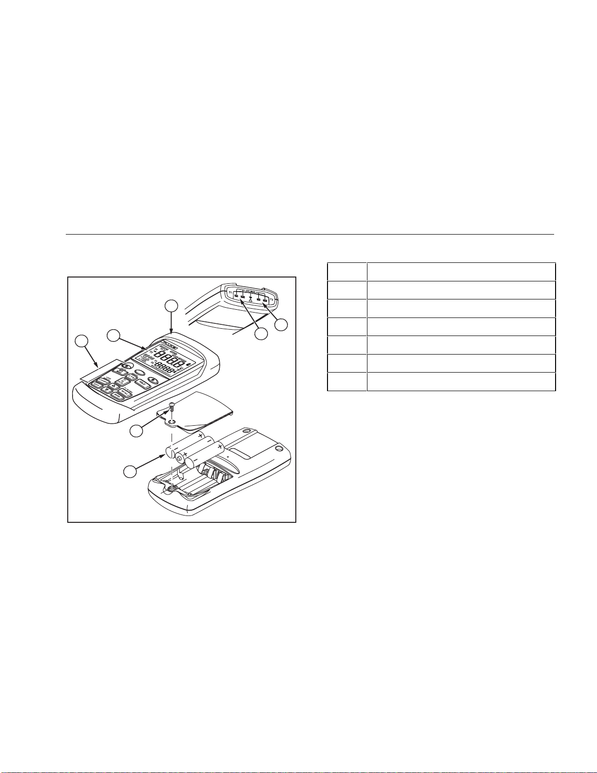
• Figure 1 and Table 3 describe the components.
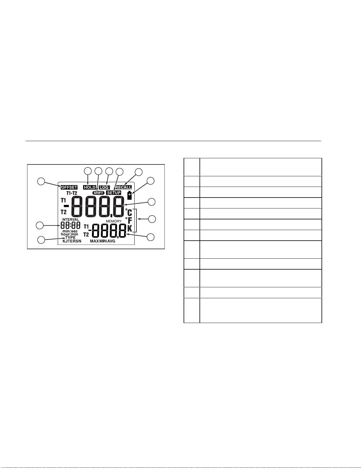
• Figure 2 and Table 4 describe the display.
• Table 5 describes the functions of the buttons.
Then read the following sections.
4
Find Quality Products Online at: [email protected]
www.GlobalTestSupply.com
Page 9
53 & 54 Series II
Getting Started
Components
5
4
3
6
7
Figure 1. Components
1
2
aat01f.eps
Table 3. Components
xx
A Thermocouple T1 input
B
Model 54:
Thermocouple T2 input
C Holster
D Display
E Buttons
F Battery door
G Batteries
5
Find Quality Products Online at: [email protected]
www.GlobalTestSupply.com
Page 10
53 & 54 Series II
Users Manual
Display Elements
1
12
11
Figure 2. Display Elements
xx
A The thermocouple measurement includes an
Table 4. Display Elements
2
3
4
5
6
7
offset. See "Changing Setup Options."
B The displayed readings do not change.
C A shift function is in progress.
8
D Readings are being logged.
E Setup is in progress.
9
F Logged readings are displayed.
10
aat02f.eps
G Low battery. Replace the batteries.
H Primary Display.
Model 54:
Model 53:
T1 reading.
T1, T2, or T1-T2 reading.
I The temperature units.
J Secondary Display: MAX, MIN, AVG, MEMORY,
or offset.
Model 54:
T1 or T2 re ading.
K The thermocouple type.
L Time Display: 24-hour clock. Shows the
INTERVAL length in SETUP. Shows elapsed time
when AVG is on or before clock has been set.
6
Find Quality Products Online at: [email protected]
www.GlobalTestSupply.com
Page 11

Buttons
53 & 54 Series II
Getting Started
Table 5. Buttons
A
G
(Shift function)
Q
M
C
Press A to turn the thermometer on or off.
Press
G, M (CANCEL) to stop displaying the minimum, maximum, and average readings in the
secondary display.
Press
G, J (CLEAR MEMORY) to delete logged readings from memory.
Press G, r (PC/IR SEND) to toggle the IR port on and off.
Press Q to turn the backlight on and off. The backlight turns off after 2 minutes without any button
presses. If the battery is low, the backlight is disabled.
Press M to step through the maximum, minimum, and average readings.
When viewing logged readings, shows the maximum, minimum, and average of the logged readings.
Press G, M (CANCEL) to turn off this display.
Press C to switch between Celsius (oC), Fahrenheit (oF), and Kelvin (K).
7
Find Quality Products Online at: [email protected]
www.GlobalTestSupply.com
Page 12

53 & 54 Series II
Users Manual
Table 5. Buttons (cont.)
h Press h to freeze or unfreeze the displayed readings.
Press h when turning on the thermometer to test the display. All display elements appear.
T
D
K
N
E
J
r
8
Model 54:
the primary or secondary display.
Press D to start or exit Setup. (See "Changing Setup Options.")
Press K to scroll to the Setup option you want to change.
Press K to increase the displayed setting.
Press N to scroll to the Setup option you want to change.
Press N to decrease the displayed setting.
Press E to enter a Setup option.
Press E again to store the displayed setting in memory.
Press J to start or stop logging.
During manual logging, the thermometer stores a single set of logged readings in memory each time you
press
Press r to show logged readings and MIN MAX readings on the display.
Press r again to stop.
Press T to toggle showing the T1, T2, and T1-T2 (differential temperature measurement) in
J.
Find Quality Products Online at: [email protected]
www.GlobalTestSupply.com
Page 13

53 & 54 Series II
Using the Thermometer
Using the Thermometer
1. Plug the thermocouple(s) into the input connector(s).
2. Press
After 1 second the thermometer displays the first reading.
If no thermocouple is plugged into the selected input or the
thermocouple is "open," the display shows
"- - - -."
A to turn on the thermometer.
Changing Setup Options
Use Setup to change the logging interval, thermocouple
type, offset, sleep mode, time, and line frequency settings.
The thermometer stores the settings in its memory. Setup
settings reset only when the batteries are removed for
more than 2 minutes.
Entering and Exiting Setup
When the thermometer is in Setup mode, the display
shows s.
• Press
D to start or exit Setup.
Notes
K
Press
want to change.
Setup is disabled in MIN MAX mode.
or N to scroll to the setup option you
9
Find Quality Products Online at: [email protected]
www.GlobalTestSupply.com
Page 14

53 & 54 Series II
Users Manual
Changing the Logging Interval
The logging interval determines how often the
thermometer stores logged readings in memory. You
choose the length of the logging interval. See "Using
Memory."
The thermometer stores logged readings at the end of
each logging interval. You can select a logging interval of
1 second (1), 10 seconds (2), 1 minute (3), 10 minutes (4),
or user-defined (
You can also set the logging interval manually (0). Each
time you press
readings in memory.
1. Press K or N until the display shows INTERVAL.
2. Press
3. Press
interval you want, and then press
USef).
J, the thermometer stores the current
E to display the logging interval choices.
K or N until the display shows the logging
E to select.
4. If you selected a user-defined logging interval:
• Press K or N until the display shows
hour:min or min:sec, and then press
select.
The left two digits blink.
• Press
• Press
Holding down
change more quickly.
K or N until the left two digits you want
appear on the display, and then press
select them .
The right two digits blink.
K or N until the right two digits you
want appear on the display, and then press
to select them.
K or N causes the number to
E to
E to
E
10
Find Quality Products Online at: [email protected]
www.GlobalTestSupply.com
Page 15

53 & 54 Series II
Changing Setup Options
Changing the Thermocouple Type
1. Press K or N until the display shows TYPE.
2. Press
3. Press
4. Press
E to display the thermocouple type choices.
The currently selected thermocouple blinks.
K or N until the thermocouple you want
appears on the display.
E to store the thermocouple type in memory.
Changing the Offset
You can adjust the thermometer’s readings to compensate
for the errors of a specific thermocouple. See "Using the
Offset to Adjust for Probe Errors." The allowable
adjustment range is ± 5.0
Model 54:
1. Press
2. Press
3. Press
4. Press
Remember to reset the offset to 0.0 when it is no longer
needed. The offset automatically resets to 0.0 when you
change the thermocouple type.
You can store individual offsets for T1 and T2.
K or N until the display shows O and
T1 or T2.
E to indicate that you want to change the
offset setting.
The temperature measurement plus the offset
appears in the primary display. The offset appears in
the secondary display.
K or N until the primary display shows the
correct reading.
E to store the offset setting in memory.
o
C or K, and ± 9.0 oF.
11
Find Quality Products Online at: [email protected]
www.GlobalTestSupply.com
Page 16

53 & 54 Series II
Users Manual
Enabling or Disabling Sleep Mode
The thermometer enters sleep mode if no button press
occurs for 20 minutes.
Pressing any button wakes the thermometer and returns it
to its previous state.
1. Press
2. Press
3. Press
4. Press
Sleep mode is enabled each time you turn on the
thermometer and is automatically disabled in MIN MAX
and logging modes.
K or N until the display shows SLP.
E to indicate that you want to change the
sleep setting.
The display shows on if sleep mode is on and 0FF if
sleep mode is off.
K or N as needed until the display shows
on or 0FF.
E to store the sleep setting in memory.
Setting the Time
1. Press K or N until the display shows the time if it
is set or shows "- - : - -."
2. Press
3. Press
4. Press
E to indicate you want to set the time.
The left two digits blink.
K or N until the display shows the correct
hour (24-hour format), and then press
The right two digits blink.
E to select.
K or N until the display shows the correct
minutes, and then press
memory.
Holding down K or N causes the number to
change more quickly.
E to store the time in
Note
12
Find Quality Products Online at: [email protected]
www.GlobalTestSupply.com
Page 17

53 & 54 Series II
Measuring Temperatures
Changing the Line Frequency
For optimum rejection of line noise, set the thermometer
for the local line frequency as follows:
1. Press
2. Press
3. Press
4. Press
K or N until the display shows Li ne.
E to indicate that you want to change the
line setting.
K or N as needed until the display shows
50 V or 60 V (50 Hz or 60 Hz).
E to store the line setting in memory.
Measuring Temperatures
Connecting a Thermocouple
Thermocouples are color coded by type based on the
North American ANSI Color Code:
Type Color Type Color
J Black R Green
K Yellow S Green
T Blue N Orange
E Purple
1. Plug a thermocouple into the input connector(s).
2. Set the thermometer for the correct thermocouple
type.
To change the thermocouple type, see “Changing
Setup Options.”
13
Find Quality Products Online at: [email protected]
www.GlobalTestSupply.com
Page 18

53 & 54 Series II
Users Manual
Displaying Temperatures
1. Press C to select the correct temperature scale.
2. Hold or attach the thermocouple(s) to the
measurement location.
The temperature reading appears in the selected
display.
Model 54:
3.
T1, T2, and T1-T2 reading in the primary or
secondary display.
The display shows "- - - -" when a thermocouple
is not connected.
The display shows
temperature being measured is outside the
thermocouple’s valid range.
Model 54: If only thermocouple T2 is connected,
the T2 reading appears in the primary display.
Press T to toggle between showing the
Notes
0L
(overload) when the
Holding the Displayed Temperatures
1. Press h to freeze the readings on the display.
The display shows H.
Model 54:
2.
T1-T2 readings in the primary or secondary display.
3. Press
Press T to toggle showing the T1, T2, or
h again to turn off the HOLD function.
Viewing the MIN, MAX, and AVG Readings
1. Press M to step through the maximum (MAX),
minimum (MIN), or the average (AVG) readings.
The elapsed time since entering MIN MAX mode, or
the time at which the minimum or maximum occurred,
appears on the display.
2. Press
G, M (CANCEL) to exit MIN MAX mode.
14
Find Quality Products Online at: [email protected]
www.GlobalTestSupply.com
Page 19

53 & 54 Series II
Using Memory
Using the Offset to Adjust for Probe Errors
Use the offset option in Setup to adjust the thermometer’s
readings to compensate for the errors of a specific
thermocouple.
1. Plug the thermocouple into the input connector.
2. Place the thermocouple in a known, stable
temperature environment (such as an ice bath or a
dry well calibrator).
3. Allow the readings to stabilize.
4. In Setup change the offset until the primary display
reading matches the calibration temperature. (See
"Changing Setup Options.")
Using Memory
During a logging session the thermometer stores logged
readings in its memory.
At the end of the logging session you can view the logged
readings on the display.
You can also transfer the logged readings to a PC running
FlukeView Forms
PC.")
FlukeView Forms
online form, which you can print or store for later use.
software. (See "Communicating with a
displays the logged readings on an
15
Find Quality Products Online at: [email protected]
www.GlobalTestSupply.com
Page 20

53 & 54 Series II
Users Manual
Initial Conditions and Data Entries
Logged readings include
The initial conditions are the thermocouple type and the
offsets for each thermocouple input. You can only view
initial conditions using
The data entries are a time stamp, the T1 reading, and the
T2 and T1-T2 readings
values by pressing
Temperature readings display 0.1 degree resolution in
FlukeView Forms.
The thermometer has 500 memory locations. The
thermometer stores 499 sets of temperature readings and
one set of initial conditions when logging continuously. It
stores 250 sets of temperature readings and 250 sets of
initial conditions when logging individual points manually.
initial conditions
FlukeView Forms
(Model 54)
r or using
and
data entries
.
. You can view these
FlukeView Forms.
Starting and Stopping Logging
.
Setup, memory clear, and PC communications are
inaccessible during logging.
1. Set the logging interval. (See “Changing Setup
Options.”)
2. Press
3. Press
4. If you selected a manual logging interval, press
J to start logging.
The display shows l.
J again to stop logging.
each time you want to store logged readings in
memory.
J
16
Find Quality Products Online at: [email protected]
www.GlobalTestSupply.com
Page 21
53 & 54 Series II
Using Memory
Clearing Memory
When memory is full, FULL appears on the display and
logging stops. You can clear memory in normal or MIN
MAX mode.
• Press
G, J (CLEAR MEMORY) to delete
logged readings from memory.
The display shows the following for 2 seconds.
MEMORY
cW f
Viewing Logged Readings
1. Press r to view logged readings.
The display shows R.
2. Press
K or N to scroll through the logged
readings.
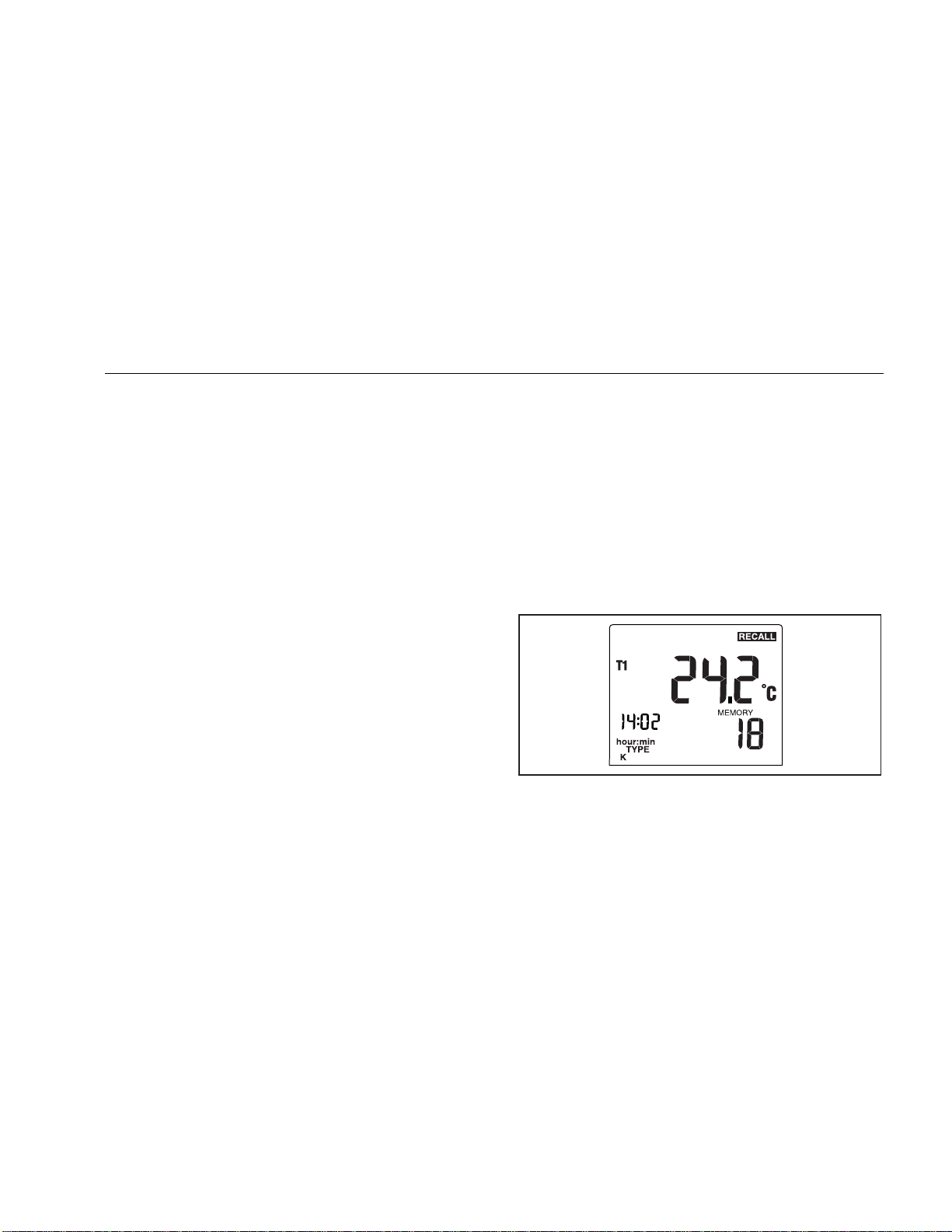
The display shows each logged reading, its time
stamp, and its memory location. For example, Figure
3 shows the logged reading stored at 2:02 PM in
memory location 18.
Figure 3. Logged Reading
aat03f.eps
17
Find Quality Products Online at: [email protected]
www.GlobalTestSupply.com
Page 22
53 & 54 Series II
Users Manual
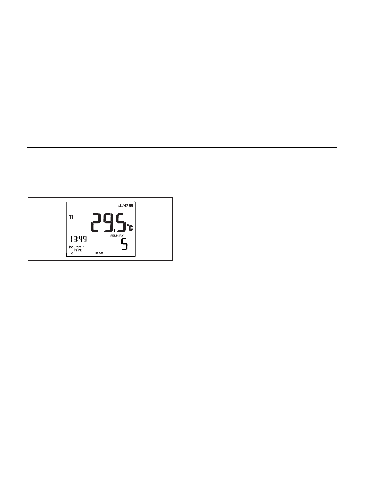
3. Press M to step through the minimum, maximum,
average, and current logged reading. For example,
Figure 4 shows the maximum reading in memory. The
maximum reading occurred at 1:49 P.M. and was
stored in memory location 5.
aat04f.eps
Figure 4. Maximum Reading
4. Press r to stop viewing logged readings.
Note
The thermometer calculates the minimum and
maximum of all logging sessions in memory.
The display shows "- - : - -" if the log is empty.
Communicating with a PC
You can transfer the contents of the thermometer’s
memory to a PC using
communication requires an IR (infrared) serial connection.
Refer to the
FlukeView
FlukeView Forms
standard (default) or customized forms. The forms also
display user comments. You can use these forms to
satisfy ISO-9000 documentation requirements.
When you send logged readings to a PC, all functions are
disabled except power off, backlight, and turning off
communication.
• Press
on and off.
The display shows:
FlukeView Forms Installation Guide
Help.
G, r (PC/IR SEND) to toggle the IR port
if
Send
When the IR port is enabled you can communicate with
FlukeView Forms
FlukeView Forms
places the logged readings into
.
. The
and
18
Find Quality Products Online at: [email protected]
www.GlobalTestSupply.com
Page 23

53 & 54 Series II
Maintenance
Maintenance
Replacing the Batteries
Refer to the safety information in Table 1 before replacing
the batteries.
1. Turn off the thermometer if necessary.
2. Loosen the screw and remove the battery door.
3. Replace the three AA batteries.
4. Replace the battery door and tighten the screw.
Cleaning the Case and Holster
Use soap and water or a mild commercial cleaner.
Wipe with a damp sponge or soft rag.
Calibration
To ensure that the thermometer performs to its accuracy
specifications, Fluke recommends that you calibrate the
thermometer annually, starting one year after purchase.
To calibrate the thermometer, contact Fluke for the
Service Center nearest you or follow the calibration
procedure in the service manual listed in "Replacement
Parts and Accessories."
Specifications
Environmental
Operating
Temperature
Storage
Temperature
Humidity Non condensing <10 oC (<50 oF)
−10 oC to 50 oC
o
(14
F to 122 oF)
−40 oC to +60 oC
o
(−40
95% RH: 10
75% RH: 30
45% RH: 40
F to +140 oF)
o
C to 30 oC (50 oF to 86 oF)
o
C to 40 oC (86 oF to 104 oF)
o
C to 50 oC (104 oF to 122 oF)
19
Find Quality Products Online at: [email protected]
www.GlobalTestSupply.com
Page 24
53 & 54 Series II
Users Manual
General
Weight 280 g (10 oz)
Dimensions
(without
holster)
Battery 3 AA batteries
Certification P,
Safety CSA C22.2 No. 1010.1 1992
CAT I OVERVOLTAGE (Installation)
* Refers to the level of Impulse Withstand Voltage protection
provided. Equipment of OVERVOLTAGE CATEGORY I is
equipment for connection to circuits in which measures are
taken to limit the transient over voltages to an appropriate low
level. Example include protect electronic circuits.
2.8 cm × 7.8 cm × 16.2 cm
(1.1 in × 3 in × 6.4 in)
s
EN 61010 Amendments 1, 2
CATEGORY I, Pollution Degree 2 per
IEC1010-1*
80 PK-1 Thermocouple (supplied with thermometer)
Type Type K, Chromel Alumel, bead style
Temperature
Range
o
−40
(−40
C to +260 oC
o
F to +500 oF)
Accuracy ± 1.1 oC (± 2.0 oF)
Electrical
Measurement
Range
Display
Resolution
J-type: −210 oC to +1200 oC
(−346
K-type: −200
(−328
T-type: −250
(−418
E-type: −150 oC to +1000 oC
(−238
N-type: −200
(−328
R- and S-type: 0
(+32
0.1 oC / oF / K < 1000
1.0 oC / oF / K ≥ 1000
o
F to + 2192 oF)
o
C to +1372 oC
o
F to +2501 oF)
o
C to +400 oC
o
F to +752 oF)
o
F to +1832 oF)
o
C to +1300 oC
o
F to +2372 oF)
o
o
F to +3212 oF)
C to +1767 oC
o
o
20
Find Quality Products Online at: [email protected]
www.GlobalTestSupply.com
Page 25

53 & 54 Series II
y
[
Replacement Parts and Accessories
Electrical (cont.)
Measurement
Accurac
or T1-T2
, T1, T2
(Model
54)
Temperature
Coefficient
Electromagnetic
Compatibility
Maximum
Differential
Common Mode
Voltage
Temperature
Scale
Applicable
Standards
Accuracy is specified for ambient temperatures
between 18
1 year. The above specifications do not include
thermocouple error.
J-, K-, T-, E-, and N-type: ±[0.05 % of
reading + 0.3
o
C (0.5 oF)]
below −100 oC (−148 oF): add 0.15 %
of reading for J-, K-, E-, and N-type;
and 0.45 % of reading for T-type]
R- and S-type: ±[0.05 % of reading +
o
C (0.7 oF)]
0.4
0.01 % of reading + 0.03 oC per oC
o
F per oF) outside the specified
(0.05
o
C to 28 oC (+64 oF to +82 oF)
+18
range
[below −100
o
C (−148 oF): add
0.04 % of reading for J-, K-, E-, and
N-type; and 0.08 % of reading for Ttype]
Susceptibility: ±2 oC (±3.6 oF) for 80
MHz to 200 MHz in 1.5 V/m field, for
200 MHz to 1000 MHz in 3 V/m field.
Emmisions: Comme rcial Limit s per
EN50081-1
1 V (Maximum voltage difference
between T1 and T2)
ITS-90
NIST-175
o
C (64 oF) and 28 oC (82 oF) for a period of
Replacement Parts and Accessories
Accessory Part Number
Holster and Flex Stand Assembly 1272438
AA NEDA 15A IEC LR6 batteries 376756
80PK-1 K-Type Bead Thermocouple 773135
CD-ROM 1276106
Service Manual 1276123
21
Find Quality Products Online at: [email protected]
www.GlobalTestSupply.com
 Loading...