

Page 1

PPC4E
Pressure
Controller/Calibrator
Operation and Maintenance Manual
© 2010 Fluke Calibration
Find Quality Products Online at: [email protected]
www.GlobalTestSupply.com
Page 2

Warning
• High pressure liquids an d gases are potentiall y hazardous. Energy sto red
in these liquids and ga ses can be released unexpectedly and with extreme
force. High pressu re systems should be a ssembled and operated onl y by
personnel who have been instructed in proper safety practices.
• The PPC4E must be properly earthed. Only use a supply outlet that has a
protective earth contact. If there is any doubt as to the effectiveness of the
supply outlet earth, do not connect the PP C4E.
• This instrument is not to be operated in any other manner than that
specified by the manufacturer.
© 2010 Fluke Calibration All rights reserved.
Information in this document is subject to change without notice. No part of this document may be reproduced or transmitted in any
form or by any means, electronic or mechanical, for any purpose, without the express written permission of Fluke Calibration, 4765
East Beautiful Lane, Phoenix, Arizona 85044-5318 USA.
Fluke Calibration makes sincere efforts to ensure the accuracy and quality of its published materials; however, no warranty,
expressed or implied, is provided. Fluke Calibration disclaims any responsibility or liability for any direct or indirect damages
resulting from the use of the information in this manual or products described in it. Mention of any product or brand does not
constitute an endorsement by Fluke Calibration of that product or brand. This manual was originally composed in English and was
subsequently translated into other languages. The fidelity of the translation cannot be guaranteed. In case of conflict between the
English version and other language versions, the English version predominates.
Products described in this manual are manufactured under international patents and one or more of the following U.S. patents:
5,142,483; 5,257,640; 5,331,838; 5,445,035. Other U.S. and international patents pending.
AutoRange, AutoZ, Fluke Calibration, FCAL, DH, DHI, COMPASS, PPC, PPC4E, RPT, RPM, RPM4, SDS and SPLT are
trademarks, registered and otherwise, of Fluke Corporation.
Document No. 3890723
100901
Printed in the USA
© 2010 Fluke Calibration Page 2
Find Quality Products Online at: [email protected]
www.GlobalTestSupply.com
Page 3

Table O f Contents
Table Of Contents ................................................................. III
Tables ................................................................................ VII
Figures .............................................................................. VIII
About This Manual ................................................................ IX
1. Introduction ..................................................................... 1
1.1 Product Overview ................................................................................................................................... 1
1.2 Specifications ......................................................................................................................................... 1
1.2.1 General Specifications ............................................................................................................................. 1
1.2.2 Pressure Measurement Specifications ................................................................................................... 2
1.2.2.1 PPC4E Models and Ranges ................................................................................................................... 2
1.2.2.2 On-Board Barometer .............................................................................................................................. 3
1.2.3 Pressure Control Specifications ............................................................................................................. 4
2. Installation ....................................................................... 5
2.1 Unpacking and Inspection ..................................................................................................................... 5
2.1.1 Removing from Packaging ...................................................................................................................... 5
2.1.2 Inspecting Contents ................................................................................................................................. 5
2.2 Site Requirements .................................................................................................................................. 6
2.3 Setup ....................................................................................................................................................... 6
2.3.1 Preparing for Operation ........................................................................................................................... 6
2.3.2 Front and Rear Panels ............................................................................................................................. 7
2.3.2.1 Front Panel ............................................................................................................................................ 7
2.3.2.2 Rear Panel ............................................................................................................................................. 7
2.3.3 Powe r Connection .................................................................................................................................... 8
2.3.4 Connecting to a Pressure Supply (Supply Port) .................................................................................... 8
2.3.5 Connecting a Vacuum Pump (Exhaust Port) .......................................................................................... 8
2.3.6 Connecting to the Device Under Test (Test(+) and Test(-) Ports) ......................................................... 8
2.3.6.1 Installing a Self Purging Liquid Trap (SPLT) ......................................................................................... 10
2.3.6.2 Installing a Dual Volume Unit (DVU), PPC4E 15 K and PPC4EX 100K ................................................ 10
2.3.7 The ATM Po rt .......................................................................................................................................... 10
2.3.8 Check/Set Security Level ....................................................................................................................... 10
2.3.9 Turn Off Absolute and Negative Gauge Mode ...................................................................................... 10
2.4 Power-Up And Verification .................................................................................................................. 11
2.4.1 Switch Power On .................................................................................................................................... 11
2.4.2 Check Pressure Measurement Operation ............................................................................................. 11
2.4.2.1 Checking Absolute Mode Pressure Measurement ................................................................................ 11
2.4.2.2 Checking Gauge Mode Pressure Measurement ................................................................................... 11
2.4.3 Leak Test ................................................................................................................................................ 11
2.4.4 Purge....................................................................................................................................................... 12
2.4.5 Check Pressure Control Operation ....................................................................................................... 12
2.5 Short Term Storage .............................................................................................................................. 12
3. Operating Principles ....................................................... 13
3.1 User Interface ....................................................................................................................................... 13
3.2 General Operating Principles .............................................................................................................. 13
3.2.1 Direct Pressure Control ......................................................................................................................... 13
3.2.2 Automated Pressure Control ................................................................................................................. 13
3.2.2.1 Dynamic Control ................................................................................................................................... 14
3.2.2.2 Static Control ....................................................................................................................................... 14
3.2.3 Pressure Ready/Not Ready .................................................................................................................... 15
3.2.4 Gauge and Negative Gauge Modes with an Absolute Reference Pressure Transducer, Dynamic
Page III © 2010 Fluke Calibration
Find Quality Products Online at: [email protected]
Compensation for Atmospheric Pres sure ............................................................................................ 16
www.GlobalTestSupply.com
Page 4

TABLE OF CONTENTS
3.2.5 Multiple RPTs ......................................................................................................................................... 17
3.2.6 Multiple Ranges (RPTs, AutoRange and Infinite Ranging) .................................................................. 18
3.2.7 AutoRange .............................................................................................................................................. 18
3.2.8 Range ...................................................................................................................................................... 20
3.2.9 Unit .......................................................................................................................................................... 20
3.2.10 Measurement Mode ................................................................................................................................ 21
3.2.11 Set Pressure Automatically ................................................................................................................... 21
3.2.12 Control .................................................................................................................................................... 22
3.2.13 Vent ......................................................................................................................................................... 23
3.2.14 AutoTest ................................................................................................................................................. 23
3.2.15 Head ........................................................................................................................................................ 24
3.2.16 Purge....................................................................................................................................................... 25
3.2.17 Leak Test ................................................................................................................................................ 26
3.2.18 Resolution .............................................................................................................................................. 26
3.2.19 Jog .......................................................................................................................................................... 27
3.2.20 Pressure Limits ...................................................................................................................................... 27
3.2.20.1 Over Pressure Function ....................................................................................................................... 28
3.2.21 Drivers .................................................................................................................................................... 28
3.2.22 Remote .................................................................................................................................................... 29
3.2.23 Reset ....................................................................................................................................................... 29
3.2.23.1 Settings ................................................................................................................................................ 29
3.2.23.2 Units..................................................................................................................................................... 30
3.2.23.3 AutoTest .............................................................................................................................................. 30
3.2.23.4 Calibration ............................................................................................................................................ 30
3.2.23.5 All ......................................................................................................................................................... 31
3.2.24 Preferences ............................................................................................................................................ 32
3.2.24.1 Screen Saver ....................................................................................................................................... 32
3.2.24.2 Sounds ................................................................................................................................................. 32
3.2.24.3 Time ..................................................................................................................................................... 32
3.2.24.4 Language ............................................................................................................................................. 33
3.2.24.5 Security ................................................................................................................................................ 33
3.2.25 Internal Functions .................................................................................................................................. 34
3.2.25.1 Identification ......................................................................................................................................... 34
3.2.25.2 Control Reference ................................................................................................................................ 35
3.2.25.3 Barometer ............................................................................................................................................ 35
3.2.25.4 Purge ................................................................................................................................................... 36
3.2.25.5 Log ....................................................................................................................................................... 36
3.2.25.6 TEST (-) Vent ....................................................................................................................................... 36
3.2.26 Calibration .............................................................................................................................................. 37
3.2.27 Measurement Uncertainty ...................................................................................................................... 37
3.2.27.1 Product Uncertainty .............................................................................................................................. 37
3.2.27.2 Span .................................................................................................................................................... 38
3.2.27.3 Head .................................................................................................................................................... 38
3.2.27.4 Zero Stability (Constant) ....................................................................................................................... 38
3.2.27.5 Control Uncertainty .............................................................................................................................. 38
3.2.27.6 Combining uncertainties ....................................................................................................................... 39
3.2.27.7 Delivered Pressure Uncertainty ............................................................................................................ 39
3.2.27.8 Using Values Other Than Default ......................................................................................................... 40
4. Operation ....................................................................... 41
4.1 Main Run Screen .................................................................................................................................. 41
4.2 Other Screens ....................................................................................................................................... 42
4.3 Keypad Layout and Protocol ............................................................................................................... 44
4.4 Conventions for the Graphical Interface ............................................................................................ 44
4.4.1 Navigation Controls and Keypad .......................................................................................................... 44
4.4.2 Navigating Menus .................................................................................................................................. 44
4.5 Pressure Control .................................................................................................................................. 47
4.5.1 Set Pressure Automatically ................................................................................................................... 47
4.5.1.1 Interrupting Automated Pressure Control.............................................................................................. 47
4.5.1.2 Automated Pressure Commands for Zero Pressure ............................................................................. 47
4.5.2 Manual Pressure Control ....................................................................................................................... 48
4.5.3 Vent ......................................................................................................................................................... 48
4.6 Graphical User Interface Menus .......................................................................................................... 48
4.6.1 Shortcuts ................................................................................................................................................ 48
4.6.2 Menu Structure ....................................................................................................................................... 48
4.7 Menu operation ..................................................................................................................................... 50
4.7.1 AutoRange .............................................................................................................................................. 50
4.7.2 AutoTest ................................................................................................................................................. 51
4.7.2.1 Exercise ............................................................................................................................................... 52
4.7.2.2 Quick Test ............................................................................................................................................ 53
© 2010 Fluke Calibration Page IV
Find Quality Products Online at: [email protected]
www.GlobalTestSupply.com
Page 5

TABLE OF CONTENTS
4.7.2.3 Advanced Test ..................................................................................................................................... 54
4.7.3 Pressure ................................................................................................................................................. 58
4.7.3.1 Purge ................................................................................................................................................... 58
4.7.3.2 Leak Test ............................................................................................................................................. 59
4.7.4 Drivers .................................................................................................................................................... 60
4.7.5 System .................................................................................................................................................... 60
4.7.5.1 Control Configuration ........................................................................................................................... 60
4.7.5.2 Reset ................................................................................................................................................... 60
4.7.6 Pressure ................................................................................................................................................. 62
4.7.6.1 Pressure Unit ....................................................................................................................................... 62
4.7.6.2 Measurement Mode ............................................................................................................................. 63
4.7.6.3 Head .................................................................................................................................................... 64
4.7.6.4 Resolution ............................................................................................................................................ 65
4.7.7 Preferences ............................................................................................................................................ 65
4.7.7.1 Screen Saver ....................................................................................................................................... 65
4.7.7.2 Sounds ................................................................................................................................................. 66
4.7.7.3 Time ..................................................................................................................................................... 66
4.7.7.4 Language ............................................................................................................................................. 66
4.7.7.5 Security ................................................................................................................................................ 67
4.7.7.6 Edit Security Password ........................................................................................................................ 67
4.7.8 Control .................................................................................................................................................... 68
4.7.8.1 Pressure Limits .................................................................................................................................... 68
4.7.8.2 Pressure Control .................................................................................................................................. 69
4.7.8.3 Jog Step ............................................................................................................................................... 69
4.7.9 Remote .................................................................................................................................................... 70
4.7.9.1 Command Format ................................................................................................................................ 70
4.7.9.2 IEEE-488.............................................................................................................................................. 71
4.7.10 Calibration .............................................................................................................................................. 71
4.7.11 Uncertainty ............................................................................................................................................. 71
4.7.12 Internal .................................................................................................................................................... 71
4.7.12.1 ID ......................................................................................................................................................... 71
4.7.12.2 Control Reference ................................................................................................................................ 71
4.7.12.3 Purge ................................................................................................................................................... 72
4.7.12.4 Event log .............................................................................................................................................. 72
4.7.12.5 TEST (-) Vent ....................................................................................................................................... 73
5. Remote Operation ........................................................... 75
5.1 Overview ............................................................................................................................................... 75
5.2 Remote Interfacing ............................................................................................................................... 75
5.2.1 RS232 Interface ...................................................................................................................................... 75
5.2.1.1 COM1 .................................................................................................................................................. 75
5.2.1.2 COM2 .................................................................................................................................................. 76
5.2.1.3 RS232 Command Testing .................................................................................................................... 76
5.2.2 IEEE-488 ................................................................................................................................................. 79
5.2.2.1 IEEE-488 Remote Command testing .................................................................................................... 79
5.3 Programming Formats ......................................................................................................................... 80
5.3.1 Classic Program Message Format ........................................................................................................ 80
5.3.2 Enhanced Program Message Format .................................................................................................... 81
5.3.2.1 Using Command Type Commands ....................................................................................................... 81
5.3.2.2 Using Query Type Commands ......................................................................................................... 82
5.4 Commands ............................................................................................................................................ 83
5.4.1 Programming Messages ........................................................................................................................ 83
5.4.2 Error Messages ...................................................................................................................................... 85
5.4.3 Program Message Description Overview ............................................................................................. 86
5.4.4 Program Message Descriptions ............................................................................................................ 87
5.5 Status Reporting System ................................................................................................................... 116
5.5.1 Error Queue ...........................................................................................................................................116
5.5.2 Status Byte Register .............................................................................................................................116
5.5.3 Standard Event Register .......................................................................................................................117
5.5.4 Ready Status Register ..........................................................................................................................118
5.6 IEEE STD. 488.2 Common and Status Program Messages............................................................. 118
5.6.1 Program Message Descriptions ...........................................................................................................119
Page V © 2010 Fluke Calibration
Find Quality Products Online at: [email protected]
www.GlobalTestSupply.com
Page 6

TABLE OF CONTENTS
6. Maintenance, Adjustments and Calibration ...................... 123
6.1 Overview ............................................................................................................................................. 123
6.2 Calibration of Reference Pressure Transducers ............................................................................. 123
6.2.1 Principle .................................................................................................................................................123
6.2.1.1 PA and PM Coefficients ......................................................................................................................124
6.2.1.2 As Received and As Left Data .............................................................................................................124
6.2.2 Equipme nt Required .............................................................................................................................125
6.2.3 Set-up and Preparation .........................................................................................................................125
6.2.4 Recommended Calibration Point Sequence ........................................................................................126
6.2.4.1 Recommended Calibration Point Sequences for PPC4E RPTs ...........................................................126
6.2.5 Turning Off Absolute and Negative Gauge Measurement Modes ......................................................128
6.2.6 RPT Calibration using CalTool for RPTs Software ..............................................................................128
6.2.7 Editing and Viewing RPT Calibration Information ...............................................................................129
6.2.7.1 RPT Uncertainty ..................................................................................................................................129
6.2.8 RPT Calibration/Adjustment without CalTool for RPTs Software ......................................................130
6.3 Adjustment of an On-board Barometer ............................................................................................ 131
6.4 Pneumatic Control Module Configuration ........................................................................................ 131
6.5 Reloading Embedded Software into Flash Memory ........................................................................ 132
6.6 Removing the PPC4E Cover .............................................................................................................. 133
6.7 Overhaul .............................................................................................................................................. 133
6.8 Subassembly Description and Location .......................................................................................... 134
6.8.1 Power Supply Module ...........................................................................................................................135
6.8.2 PowerPC Board .....................................................................................................................................135
6.8.3 RPT MODULE ........................................................................................................................................135
6.8.3.1 Hi RPT ................................................................................................................................................135
6.8.3.2 Lo RPT ................................................................................................................................................135
6.8.4 On-board Barometer .............................................................................................................................135
6.8.5 Vacuum Sensor .....................................................................................................................................135
6.8.6 Pressure Control Module ......................................................................................................................136
6.8.7 Display ...................................................................................................................................................136
6.8.8 Driver Board ..........................................................................................................................................136
6.9 Pneumatic Schematics ...................................................................................................................... 136
6.9.1 PPC4E Pressure Control Module .........................................................................................................136
6.9.2 PPC4E Reference Pressure Transducer Module Configurations .......................................................137
7. Troubleshooting............................................................ 139
8. Appendix ...................................................................... 143
8.1 Drivers ................................................................................................................................................. 143
8.2 Unit Conversion .................................................................................................................................. 144
8.2.1 Pressure ................................................................................................................................................144
9. Limited Warranty and Limitation of Liability .................... 145
10. Glossary ...................................................................... 147
© 2010 Fluke Calibration Page VI
Find Quality Products Online at: [email protected]
www.GlobalTestSupply.com
Page 7

Tables
Table 1. PPC4E Model Designations and Ranges ...................................................................................... 2
Table 2. PPC4E Measurement Uncertainty (Includes Precision) ................................................................ 3
Table 3. PPC4E Packing List ....................................................................................................................... 5
Table 4. Position Designators of RPTs in a PPC4E System ..................................................................... 17
Table 5. Settings and What They Are Specific To (Range, Measurement Mode, RPT, System) ............. 18
Table 6. Settings Made by AutoRange ...................................................................................................... 19
Table 7. Default Pressure Control Parameters!!! ....................................................................................... 23
Table 8. Reset Settings .............................................................................................................................. 30
Table 9. Reset Calibration.......................................................................................................................... 31
Table 10. Reset All ..................................................................................................................................... 31
Table 11. Security Levels, Advanced Interface.......................................................................................... 34
Table 12. Main Run Screen Fields and Buttons ........................................................................................ 42
Table 13. Lower Level Screen Displays and Selectable Fields ................................................................. 43
Table 14. Menu Structure........................................................................................................................... 49
Table 15. COM1 Pin Designations and Connections ................................................................................ 75
Table 16. COM2 DB-9F Pin Designations ................................................................................................. 76
Table 17. Program Message List ............................................................................................................... 83
Table 18. Error #s and Descriptions .......................................................................................................... 85
Table 19. 8 Bit Status Byte Register ........................................................................................................ 116
Table 20. 8 Bit Standard Event Register .................................................................................................. 117
Table 21. 8 Bit Ready Status Register ..................................................................................................... 118
Table 22. Program Message List ............................................................................................................. 118
Table 23. Calibration Point Sequence, A200K RPTs .............................................................................. 127
Table 24. Calibration Point Sequence, A1.4M and A700K RPTs ............................................................ 127
Table 25. Calibration Point Sequence, A7M and A14M RPTs ................................................................ 127
Table 26. Calibration Point Sequence, BG15K RPTs .............................................................................. 127
Table 27. PPC4E Troubleshooting Guide ................................................................................................ 139
Table 28. External Drivers Current Output ............................................................................................... 143
Table 29. External Drivers Pin Outs ......................................................................................................... 143
Table 30. Pressure Unit of Measure Conversion Coefficients ................................................................. 144
Table 31. Fluke Calibration Authorized Service Providers ...................................................................... 146
Page VII © 2010 Fluke Calibration
Find Quality Products Online at: [email protected]
www.GlobalTestSupply.com
Page 8

TABLES AND FIGURES
Figures
Figure 1. PPC4E front panel ........................................................................................................................ 7
Figure 2. PPC4E rear panel ......................................................................................................................... 7
Figure 3. Dynamic Pressure Control Operation ......................................................................................... 14
Figure 4. Static Pressure Control Operation .............................................................................................. 15
Figure 5. Ready/Not Ready in Dynamic Pressure Control Mode .............................................................. 16
Figure 6. Ready/Not Ready in Static Control Mode ................................................................................... 16
Figure 7. Main Run Screen Display and Selectable Fields (see Table 12) ............................................... 41
Figure 8. Lower Level Screen Example (see Table 13) ............................................................................. 43
Figure 9. Keypad layout ............................................................................................................................. 44
Figure 10. AutoRange Bar ......................................................................................................................... 51
Figure 11. Windows selection of Hyperterminal......................................................................................... 76
Figure 12. Hyperterminal Initial Display ..................................................................................................... 76
Figure 13. Hyperterminal ASCII Setup ....................................................................................................... 78
Figure 14. Status Register Schematic ..................................................................................................... 116
Figure 15. Removing Back Cover ............................................................................................................ 133
Figure 16. PPC4E Internal View .............................................................................................................. 134
Figure 17. Pressure Control Module Schematic ...................................................................................... 136
Figure 18. PPC4E Reference Pressure Transducer Module Schematics ............................................... 138
Figure 19. Drivers Connector Schematic ................................................................................................. 143
© 2010 Fluke Calibration Page VIII
Find Quality Products Online at: [email protected]
www.GlobalTestSupply.com
Page 9

About This Manual
This manual is intended to provide the user with the basic information necessary to operate a PPC4E
pressure controller/calibrator. It also includes a great deal of additional information provided to allow you
to optimize PPC4E use and take full advantage of its many features and functions.
Before using the manual, take a moment to familiarize yourself with the Table of Contents structure:
Sections 1, 2 and 3 should be read by all first time PPC4E users. Section 4 is important for those using
the Advanced user interface. Section 5 is for remote operation from an external computer. Section 6
provides maintenance and calibration information. Section 7 is a quick troubleshooting guide. Use it to
troubleshoot unexpected PPC4E behavior based on the symptom of that behavior. Certain words and
expressions have specific meaning as they pertain to PPC4E. The Glossary, Section 10 is useful as a
quick reference for exact definition of specific words and expressions as they are used in the manual.
Note
For those who “don’t read manuals”, go directly to Section 2.3 to set up your
PPC4E and then go to Section 2.4 for power-up and verification. This will get you
up and running quickly with a minimal risk of causing damage to yourself or your
new PPC4E. THEN…when you have questions or start to wonder about all the
Manual Conventions
great features you might be missing, ge t into the manual!
Note
• This manual is written for both PPC4E and PPC4EX. PPC4EX is a
configuration of PPC4E with extended AutoRange turndown.
• When the term “PPC4E” is used alone, it typically refers to both PPC4E and
PPC4EX collectively.
• Detailed description of menu structure, key press sequences and
conventions are found in Section 4.
• For dedicated front panel keys, such as , , , and , an y time a
key is shown in the manual, it should be interpreted to mean “press this
key”. For example: to return to the Main Run Screen means “Press the
button to return to the Main Run Screen”.
• The electronic version of this manual ma kes extensive use of hot links for
the table of contents, figure references, table references and all section
references found throughout. Simply click on a reference to follow the live
link.
Caution
“Caution” is used throughout the manual to identify conditions or actions that
could cause harm to the PPC4E or to the devices that are connected to the PPC4E.
Warning
“Warning” is used in throughout the manual to identify actions that could pose a
hazard to the user of the PPC4E.
Note
“Note” is used throughout the manual to identify operating and applications advice
Page IX © 1998-2010 Fluke Calibration
Find Quality Products Online at: [email protected]
and additional explanations.
www.GlobalTestSupply.com
Page 10

1. Introduction
1.1 Product Overview
PPC4E is a stand-alone pressure controller intended for precision setting and control of gas pressure into a
closed volume as is commonly needed for the calibration and testing of pressure measuring instruments. It
has been designed to provide very high performance combined with versatility and ease of use.
Model “PPC4E” is equipped one Reference Pressure Transducers (RPT) and model PPC4EX is equipped
with two RPTs to allow it to set and measure pressure with low measurement uncertainty.
Pressure control is achieved by a patented pneumatic module based on digitally controlled solenoid
valves and differential pressure regulators.
PPC4E is controlled locally by the operator using a front panel display, keypad and function keys or
remotely by a computer using ASCII character command strings over RS232 or IEEE-488.2.
PPC4E models are available to support measure and control pressure in ranges from as low as - 1 to 1 kPa
(-0.15 to 0.15 psi) to as high as 14 MPa (2 000 psi), and feature absolute, gauge and compound gauge
pressure measurement modes.
1.2 Specifications
1.2.1 General Specifications
Power Requirements
Operating Temperature Range 10 to 40 °C
Storage Temperature Range -20 to 70 °C
Vibration Meets MIL-PRF-28800F Class 3
Weight 16.6 kg (36.5 lb)
Dimensions 19 cm H x 35 cm W x 45 cm D (7.5 in. x 13.8 in. x 17.7 in.)
Ventilation To prevent product overheating, provide proper ventilation. Allow 10 cm (4 in.)
Microprocessors Motorola 68302, 16 MHz
Remote communication interfaces RS232 (COM1, COM2), IEEE-488.2, USB (front panel, firmware load only)
Fuses 1 A, 250 VAC fuse, 5 x 20 mm, time lag type fuse. Internal power supply fuse
Pressure Ranges
Operating Medium Any clean, dry, non-corrosive gas
Pressure Connections
Pressure Limits
100 to 240 VAC (-15%, +10%), 50-60 Hz, 70 VA max consumption
clearance from rear panel cooling fan.
not replaceable by operator: 2A, 250 V (UV 440-2 power supply), 3.15A,
250 V (NFS40-7612 power supply)
Vacuum to 14 MPa (2 000 psi) see
User is responsible for any and all safety precautions
associated with hazardous, flammable or toxic gas ventilation
and containment.
TEST (+), TEST (-): 1/8 in. NPT F
SUPPLY: 1/8 in. NPT F
EXHAUST: 3/8 in. NPT F
ATM: 10-32 UNF
Maximum working:pressure: PPC4E range maximum
Maximum test pressure:w/out damage: 115 % of PPC4E range
Recommended supply: pressure: Maximum control pressure + 10 %
Table 1.
Warning
Page 1 © 1998-2010 Fluke Calibration
Find Quality Products Online at: [email protected]
www.GlobalTestSupply.com
Page 11

PPC4™ OPERATION AND MAINTENANCE MANUAL
1.2.2 Pressure Measurement Specifications
1.2.2.1 PPC4E Models and Ranges
PPC4E family of pressure controller/calibrator measurement and control ranges are
achieved by using one internal reference pressure transducer (RPT) in PPC4E
models and two RPTs in PPC4EX models. PPC4E and PPC4EX models with
similar numeric model designations cover similar maximum pressure ranges,
however the uncertainty of pressure measurements at the low end of the pressure
range is a function of the AutoRanged Span (see Section 3.2.7). Uncertainties scale
with AutoRanged spans as low as 10% of the controller span for PPC4E models and
as low as 1% of the controller span for PPC4EX models.
All PPC4E and PPC4EX models have only one TEST(+) and TEST(-) port. PPC4E
internal valves and logic handle switching between the two RPTs as needed.
Table 1. PPC4E Model Designations and Ranges
Warm Up Time
Resolution
Acceleration Effect
Predicted One Year Stability
Precision
MODEL
DESIGNATION
PPC4EX 14M A14M A1.4M
PPC4E 14M A14M -
PPC4EX 7M A7M A700K
PPC4E 7M A7M -
PPC4EX 1.4M A1.4M A200K
PPC4E 1.4M A1.4M -
PPC4EX 100K A200K BG15K
PPC4E 100K A200K -
PPC4E 15K BG15K - ±15 ±2.2 - -
1
Pressure range is nominal measurement range. See pressure control specifications (Section 1.2.3)
for lowest controllable pressure.
2
ATM represents the current atmospheric pressure. –ATM is the lowest pressure achievable in
negative gauge mode (vacuum).
None required, 30 minute temperature stabilization recommended for best performance from
cold power up
To 1 ppm, user adjustable
± 0.008 % /g maximum, worst axis
Allows operation at ± 20° from reference plane without significant effect
± 0.005% of reading for gauge or negative mode or ± (0.005% + Constant uncertainty from
Table 2) for absolute mode, k=2
0.019% of AutoRanged span or better for AutoRanged span equal to or greater than the
Minimum AutoRanged span (see Table 2).
Hi RPT Lo RPT
Gauge
2
[kPa]
-ATM to
14 000
-ATM to
7 000
-ATM to
1 400
-ATM to
100
PRESSURE RANGE1
Gauge
[psi]
-ATM to
2 000
-ATM to
1 000
-ATM to
200
-ATM to
15
Absolute
2
[kPa]
0 to
14 000
0 to
7 000
0 to
1 400
0 to 200 0 to 30
Absolute
[psi]
0 to
2 000
0 to
1 000
0 to 200
© 2010 Fluke Calibration Page 2
Find Quality Products Online at: [email protected]
www.GlobalTestSupply.com
Page 12

1. INTRODUCTION
Table 2. PPC4E Measurement Uncertainty (Includes Precision)
Gauge Uncertainty
Equal to % of AutoRanged span
% of
Model
AutoRanged
span
AutoRanged span
PPC4EX 14M 0.02 140 0.02 0.1 140
PPC4E 14M 0.02 1 400 0.02 1 1 400
PPC4EX 7M 0.02 70 0.02 0.05 70
PPC4E 7M 0.02 700 0.02 0.5 700
PPC4EX 1.4M 0.02 14 0.02 0.014 70
PPC4E 1.4M 0.02 140 0.02 0.1 140
PPC4EX 100K 0.02 ± 1 0.02 0.014 70
PPC4E 100K 0.02 ± 10 0.02 0.014 70
PPC4E 15K 0.02 ± 1.5 - - -
1. Maximum deviation of the RPT indication from the true value of applied pressure including precision, predicted one year stability limit,
temperature effect and calibration uncertainty, combined and expanded (k=2) following the ISO “Guide to the Expression of Uncertainty in
Measurement.”
2. For AutoRange spans below the Minimum AutoRanged span uncertainty is equal to the value at the Minimum AutoRanged span.
3. Gauge uncertainty is a % of AutoRanged span. For example, an AutoRanged span of 3 500 kPa on model PPC4E 7M would have
uncertainty of (0.02% * 3 500 kPa) = 0.70 kPa.
4. Absolute uncertainty is the sum of a % of AutoRanged span and a Constant that accounts for zero drift. For example, an AutoRanged span
of 80 kPa on model PPC4EX 100K would have uncertainty of (0.02% * 80 kPa + 0.014 kPa) = 0.03 kPa.
1
Minimum
2
[kPa]
3
Absolute Uncertainty
Equal to % of AutoRanged span + Constant
% of
AutoRanged
span
Constant
[kPa]
AutoRanged span
1
Minimum
[kPa]
4
2
1.2.2.2 On-Board Barometer
The on-board barometer is used only to measure changes in atmospheric
pressure to provide dynamic compensation of an absolute RPT’s atmospheric
pressure offset in gauge measurement mode with PPC4E models other than
PPC4E 15k.
Warm Up Time
Range
Resolution
Precision
None required
70 to 110 kPa (10 to 16 psi)
0.001 % of span
0.14 kPa
Page 3 © 2010 Fluke Calibration
Find Quality Products Online at: [email protected]
www.GlobalTestSupply.com
Page 13

PPC4™ OPERATION AND MAINTENANCE MANUAL
Typical Pressure Setting Ready Time
(0.005% hold limit, 50 cc test volume)
Slew Time
(ATM to FS with 50 cc test volume)
1.2.3 Pressure Control Specifications
Control Precision
Lowest controllable Pressure
(gauge mode)
Lowest controllable Pressure
(absolute, negative gauge modes)
Ultimate Pressure
(absolute, negative gauge)
Depending on vacuum pump and connections
PPC4E:
±0.0006% of controller span
PPC4EX:
±0.0006% of controller span (AutoRanged span >10% of
controller span)
±0.00006% of controller span (AutoRanged span ≤10% of
controller span)
Zero set by automated venting. Lowest point above or below
zero limited only by RPT resolution and control precision.
1 kPa for all models except PPC4E 7M and PPC4E 14M
3.5 kPa for PPC4E 7M
7 kPa for PPC4E 14M
200 to 700 Pa (2 to 7 mbar, 0.03 to 0.1 psia)
15 to 30 s
30 s
Typical Test Volume
Default Dynamic Control Hold Limit
0 to 1000 cc for Controller Range of 1.4 MPa [300 psi] or less
0 to 500 cc for Controller Range greater than 1.4 MPa [300 psi]
± 0.01 % of current range
Find Quality Products Online at: [email protected]
© 2010 Fluke Calibration Page 4
www.GlobalTestSupply.com
Page 14

2. Installation
2.1 Unpacking and Inspection
2.1.1 Removing from Packaging
PPC4E is delivered in a corrugated container with suspension packaging; or in an optional
molded shipping case with custom foam inserts.
Remove the PPC4E and its accessories from the shipping container and remove each
element from its protective plastic bag.
2.1.2 Inspecting Contents
Check that all items are present and have no visible damage.
A PPC4E includes all items indicated in Table 3.
Table 3. PPC4E Packing List
DESCRIPTION PAR T #
PPC4E Pressure Controller/Calibrator
(one of listed models):
PPC4E 14M
PPC4EX 14M
PPC4E 7M
PPC4EX 7M
PPC4E 1.4M
PPC4EX 1.4M
PPC4E 100K
PPC4EX 100K
PPC4E 15K
1 ea. Calibration Certificate 3152121
1 ea. Test Report 3126112
ACCESSORIES: 3846495
1 ea. User Manual 3890723
1 ea. Drivers Connector 3069838
1 ea. USB Cable, 2 Meter, Shielded 1626219
1 ea. Power Cord (7.5 ft.) 3133781
1ea. Power Cord, CE (7.5 ft.) 3153005
1 ea. General Accessories CD 3139043
2 ea. Bulkhead Retainer, ½ in. hex 3138166
2 ea. M4 Split Lock Washer 3153914
2 ea. M4 x 8 Screw, BHSC 3361394
2 ea. M3 x 20 Screw, SHC 3133921
3842637
3842628
3842619
3842604
3842598
3842580
3842571
3842567
3842559
Page 5 © 1998-2010 Fluke Calibration
Find Quality Products Online at: [email protected]
www.GlobalTestSupply.com
Page 15

PPC4™ OPERATION AND MAINTENANCE MANUAL
2.2 Site Requirements
The PPC4E can be installed on any flat, stable surface at a convenient height. The front feet can be
extended so that the unit can be inclined for easier viewing. The PPC4E can also be mounted in a
standard 19 in. rack using the optional rack mount kit.
Minimizing the distance between the PPC4E and the device or system under test will enhance control
performance and reduce pressure setting times.
Ready access to the PPC4E rear panel should be considered to facilitate making and breaking
pressure connections.
The Self Purging Liquid Trap (SPLT), if used, should be mounted vertically at the low point of the
connection between the PPC4E TEST(+) port and the test (see Section 2.3.6.1).
PPC4E 15K and PPC4EX 100K must be set up with a Dual Volume Unit (DVU). Its location and
connections should be considered (see Section 2.3.6.2).
Support facilities required include:
• An electrical power source of 100 to 240 VAC, 50 - 60 Hz.
• A continuous, regulated pressure supply of clean, dry, non-corrosive gas at PPC4E maximum
control pressure + 10 % (70 kPa (10 psi) in the case of a PPC4E 15K) to be connected to the PPC4E
SUPPLY port. Lower gas pressure supply can be used but should exceed the maximum desired test
output pressure by 10 to 20 %.
• A vacuum source of less than 1 psi absolute (7 kPa) and with displacement of at least 90 lpm (3
cfm) if control of pressures under 3 psi (20 kPa) gauge is desired.
2.3 Setup
2.3.1 Preparing for Operation
To prepare PPC4E for check out and operation:
Remove the plastic caps from the PPC4E rear panel pressure connections.
Remove the protective plastic sheet from the front panel display.
Familiarize yourself with the front and rear panel (see Section 2.3.2).
Then proceed with Sections 2.3.3 to 2.3.9.
© 2010 Fluke Calibration Page 6
Find Quality Products Online at: [email protected]
www.GlobalTestSupply.com
Page 16

2. INSTALLATION
2.3.2 Front and Rear Panels
2.3.2.1 Front Panel
Ready/Not Ready indicator
Controlled pressure measurement
Display
Multi-function keypad
Vent Indicator
Direct pressure control keys
Cursor control keys
Select and Enter knob
Remote activity indicator
USB connection
Figure 1. PPC4E front panel
2.3.2.2 Rear Panel
ATM port
COM2 Connector
IEEE-488 Connector
COM1 Connector
Power Switch
Fuse
Electrical Power Connector (IEC-320-C13)
Figure 2. PPC4E rear panel
Product Label
Pressure Connection, TEST(+)
Pressure Connection, TEST(-)
Pressure Connection, SUPPLY
Pressure Connection, EXHAUST
Drivers (12 V) Connector
Page 7 © 2010 Fluke Calibration
Find Quality Products Online at: [email protected]
www.GlobalTestSupply.com
Page 17

PPC4™ OPERATION AND MAINTENANCE MANUAL
2.3.3 Power Connection
Check that the PPC4E power switch is OFF.
Connect the supplied power cable to the rear panel power module.
Connect the other end of the power cable to an electrical supply of 100 to 240 VAC,
50-60 Hz.
2.3.4 Connecting to a Pressur e Supply (Supply Port)
Using a pressure connecting hose or tube of appropriate pressure rating, connect the
pressure supply to the SUPPLY port on the rear panel of PPC4E. The PPC4E SUPPLY port
connection is 1/8 in. NPT female.
The supply pressure should be equal to the maximum PPC4E control pressure + 10 % (or
70 kPa (10 psi) for a PPC4E 15K). Lower gas pressure sources can be used but should
exceed the maximum desired test output pressure by 10 to 20 %.
Never connect a pressure supply greater than 20 % over the maximum
pressure of the PPC4 E m aximum pressure range (except with PPC4E 15K
as specified ). Be su r e to connect the pressure supply to the SUPPLY port.
Connecting to another port can damage the PPC4E.
Caution
2.3.5 Connecting a Vacuum Pump (Exhaust Port)
For PPC4E to set pressures under atmosphere and/or to reliably set pressure under 20 kPa (3
psi) gauge (other than zero gauge), a vacuum supply must be connected to the EXHAUST
port.
Caution
• Never connect a pressure supply to or plug the PPC4E EXHAUST port.
• To avoid building up pressure on the EXHAUST port or on a vacuum
pump connected to the EXHAUST port, the vacuum source should
either be continuously ON or the EXHAUST port should be byp assed
to atmosphere when the vacuum source is OFF. This is because when
a supply pressure is applied to the PPC4E SUPPLY port and the
PPC4E is NOT in the vent ON condit ion, there is typically a constant
gas exhaust through the PPC4E EXHAUST port.
Note
To ensure optimum pressure control w hen changing the p ressure applied
to the EXHAUST port from vacuum to atmosphere or vice-versa, be sure to
change the control reference setting if the setting is NOT in AUTO mode
(see Section 3.2.25.1).
2.3.6 Connecting to the Device Under Test (Test(+) and Test(-) Ports)
If you are using a self purging liquid trap (SPLT), see Section 2.3.6.1 before proceeding to
connect the device under test.
If the PPC4E is model PPC4E 15K or PPC4EX 100K, a dual volume unit (DVU) should be
installed for very low pressure control. See Section 2.3.2.2 before proceeding to connect to the
device under test.
Using a pressure connecting hose or tube of appropriate pressure rating, connect the device or
system to be tested to the PPC4E TEST(+) port. The PPC4E TEST(+) connection is 1/8 in. NPT
© 2010 Fluke Calibration Page 8
Find Quality Products Online at: [email protected]
female.
www.GlobalTestSupply.com
Page 18

2. INSTALLATION
PPC4E TEST(+) AND TEST(-) PORTS
All PPC4Es have a TEST(+) and a TEST(-) port. See Figure 18 for configuration of
Reference Pressure Transducers (RPTs) and the internal barometer in the different PPC4E
models.
• When operating in absolute mode: The TEST(-) port is left open to atmosphere.
• When operating in gauge or negative gauge mode with a range greater than 50 kPa
(7.5 psi): The TEST(-) port is normally left open to atmosphere. A possible exception is
when the device or system under test is in an ambient pressure that may differ significantly
from the ambient pressure around the PPC4E. For example, if the PPC4E is controlling
pressure into UUTs in an environmental chamber, the pressure in the environmental chamber
may be different from ambient pressure around the PPC4E. In this case, connecting a tube
from the TEST(-) port to the inside of the chamber may improve measurement results. This
tube must be left open to the environment so that the pressure inside cannot deviate too far
from ambient.
• When operating in gauge or negative gauge mode with a range less than 50 kPa (7.5 psi):
As a general rule, it is preferable to connect the PPC4E TEST(-) port(s) directly to the low
or reference side of the device under test to ensure that these are at the same pressure.
In most cases, this tube must be left open to the environment so that the pressure inside
cannot deviate too far from ambient. The exception is when using a PPC4E 15K or
PPC4EX 100K AutoRanged to 10 kPa or less, for which more stable results may be
obtained by closing this connectionoff from ambient pressure to reduce line pressure
fluctuations.
Caution
• Do not apply pressure to the TEST(+) port without having a pressure
supply equal to or greater than th e applied pressure connect ed to the
SUPPLY port. When controlling pressure to the TEST(+) port
externally, do not cause the pressure to change at a rapid rate. For
example, do not v ent sud denly b y open ing an extern al valv e. Int ernal
damage to the PPC4E may result.
• Do not connect a pressure supply to the TEST(-) port. The pressure
applied to this port should be maintained at atmospheric pressure,
between 70 and 110 k Pa (10 and 16 p sia). E xceed ing these l imits m ay
damage the PPC4E.
• Operating the PPC4E con nected to a system with liquid contaminants
without taking proper precautions to purge the system and test line
may cause contamination of the PPC4E that will req uire non-warranty
service.
Note
• Minimizing the length of the test connection tubing will enhance
control performance and reduce pressure setting time. For normal
operation, the total volume of the device or system under test
including connecting tubing should be less than 1 000 cc (60 in
2 000 kPa (300 ps i) and less than 500 cc (30 i n 3) above 2 000 k P a ( 3 00
psi).
• PPC4E pressure control will not operate properly if there are excessive
leaks in the test system. In general, the maximum acceptable leak rate
for optimal PPC4E automated pressure control operation and to
ensure in tolerance measurements with default pressure control
parameter s is ± 0.5 % of s et pr essur e/mi nute. In DY N AMIC CO NTRO L
mode, to han dle highe r test syst em leak rate s, increas e the hold l imit
using CUSTOM CONTROL (see Section 3.2.12).
• PPC4E pressure control may be adversely affected if the test
connection tubing is too restrictive. For optimum results, the inner
diameter of the connecting hose should be at least 1.75 mm (0.07 in.).
3
) up to
Page 9 © 2010 Fluke Calibration
Find Quality Products Online at: [email protected]
www.GlobalTestSupply.com
Page 19

PPC4™ OPERATION AND MAINTENANCE MANUAL
2.3.6.1 Installing a Self Pur ging Liquid Trap (SPLT)
The SPLT (optional) is intended to collect and exhaust liquid or other
contaminants that may be present in the device or system under test so that they
do not return to contaminate the PPC4E.
The SPLT is installed in the TEST(+) connection line at a low point between
PPC4E and the device or system under test.
See the SPLT Operation and Maintenance manual for more complete
instructions on SPLT installation.
2.3.6.2 Installing a Dual Vo lume Unit (DVU), PPC4E 15 K and PPC4EX 100K
To achieve in tolerance pressure control with the very low range of the PPC4E 15K and
PPC4EX 100K, a PK-PPC-BG-DVU dual volume unit should be installed in-line on
the TEST(+) and TEST(-) ports. The DVU includes two thermally isolated
volumes installed in the test line to improve control stability.
See the PK-PPC-BG-DVU instruction sheet for additional information on its
installation.
2.3.7 The ATM Port
The PPC4E ATM port is the system vent to atmosphere point used to set zero gauge pressure as
well as to obtain reference pressure measurements of atmospheric pressure. Although a
pressure hose can be connected to the ATM port to direct the vented gas flow, a completely
unobstructed connection to atmosphere must be maintained for PPC4E reference pressure
measurements to operate normally.
The PPC4E ATM port fitting is 10-32 UNF.
Caution
NEVER plug, obstruct or connect a supply pressure to the PPC4E ATM
port. This may adversely affect GA UGE mode operation.
2.3.8 Check/Set Security Level
PPC4E has a security system based on user levels. By default, the security system is set to
“low”, which includes certain access restrictions, and there is no password required to change
the security level. See Section 3.2.24.4 for information on the security level system. As part
of the PPC4E startup, determine the security level that is appropriate for the PPC4E and set
a password if desired.
Caution
PPC4E is delivered with the security level set to “low” to avoid inadvertent
altering of critical internal settings but with access to changing security
levels unrestricted. It is recommended that the low security level be
maintained at all tim es an d pa ssw ord prote ction b e imp lemente d if c ont rol
over setting of security levels is desired.
2.3.9 Turn Off Absolute and Negati ve Ga uge M ode
Most PPC4E onfigurations are able to operate in gauge, negative gauge and absolute
measurement modes (see Section 3.2.10). PPC4E 15K operates only in gauge or negative
gauge mode. If the PPC4E will be used only in gauge mode, the other measurement modes
can be turned off so they are no longer accessible. This can avoid confusion and/or
accidental use of the wrong measurement mode. See Section 0 for complete information on
turning off absolute and negative gauge measurement modes.
© 2010 Fluke Calibration Page 10
Find Quality Products Online at: [email protected]
www.GlobalTestSupply.com
Page 20

2. INSTALLATION
2.4 Power-Up And Verification
2.4.1 Switch Power On
Actuate the power switch on the PPC4E rear panel. Observe the front panel display as
PPC4E initializes error checks and goes to the Main Run Screen (see Section 4.1).
PPC4E power-up condition is ranged to the PPC4E maximum pressure, VENT ON unless the
pressure measured by the active reference pressure transducer is more than 20 kPa (3 psi)
away from standard atmospheric pressure.
If the PPC4E fails to reach the Main Run Screen, service is required. Record the sequence
of operations and displays observed.
2.4.2 Check Pressure Measurement Operation
2.4.2.1 Checking Absolute Mode Pressure Measurement
If the PPC4E is not vented (VENT LED OFF), to vent the PPC4E (VENT LED
ON) (see Section 3.2.13) and wait for a Ready indication (see Section 3.2.3).
Use the PPC4E AutoRange function to select or configure an absolute pressure
range near the maximum pressure of the PPC4E (see Section 4.7.1). Verify the
PPC4E is vented. Observe the current value of atmospheric pressure. Check
that the value agrees with the local value of atmospheric pressure within PPC4E
measurement tolerance as applicable (see Section 1.2.3). If they do not agree
within tolerances, the PPC4E may require repair or calibration.
If the PPC4E is model PPC4EX 1.4M, PPC4EX 7M or PPC4EX 14M, use the
PPC4E AutoRange function to select or configure gauge pressure range near 8%
of the maximum absolute pressure of the PPC4E (see Section 4.7.1). Verify the
PPC4E is vented. Check that the value agrees with the local value of
atmospheric pressure within PPC4E measurement tolerance as applicable.
2.4.2.2 Checking Gauge Mode Pressure Measurement
If the PPC4E is not vented, to vent it (see Section 3.2.13).
Note
It is normal for PPC4E to indicate a value other than zero when
vented when gauge mode is first entered or ranges are
changed. After about ten seconds, the vent LED should flash
and zero should be indicated.
Use the PPC4E AutoRange function to select or configure gauge pressure range
near the maximum pressure of the PPC4E (see Section 4.7.1). Verify the
PPC4E is vented. Observe that, within ten seconds, zero pressure is indicated. It is
normal for PPC4E to indicate a value other than zero for up to ten seconds when
first entering gauge mode.
If a “PPC4EX” model, use the PPC4E AutoRange function to select or configure
gauge pressure range near 5% of the maximum gauge pressure of the PPC4E
(see Section 4.7.1). Verify the PPC4E is vented. Observe that, within ten
seconds, zero pressure is indicated.
2.4.3 Leak Test
If desired, perform a leak check of the test system (see Section 3.2.17).
Page 11 © 2010 Fluke Calibration
Find Quality Products Online at: [email protected]
www.GlobalTestSupply.com
Page 21

PPC4™ OPERATION AND MAINTENANCE MANUAL
2.4.4 Purge
If an SPLT is included and installed in the test line (see Section 2.3.6.1) and the Device Under Test
(UUT) may be contaminated with liquids, perform a purge of the UUT (see Section 3.2.25.4).
The Purge function must first be enabled (see Section 4.7.12.3). This will help to expel
contaminating liquids from the UUT.
Operating the PPC4E connected to a system with liquid contaminants
without taking proper precautions to purge the system and test line may
cause contamination of the PPC4E that will require non-warranty service.
2.4.5 Check Pressure Control O per a ti on
Select a pressure range using [AutoRange], Range: (see Section 4.7.1).
Select dynamic control mode with the control mode shortcut (see 4.6.1 and
Section 4.7.8.2). to return to the Main Run Screen.
, key in a target pressure within the active range and .
(see Section 4.5.1).
Caution
Caution
Verify the maximum pressure rating of the system connected to the
PPC4E TEST(+) port before entering a target pressure. Do not enter a
target pressure greater than the pressure rating of the system connected
to the PPC4E TEST(+ ) po rt.
PPC4E should set the target pressure and indicate Ready (see Section 3.2.3) continuously in
15 to 60 seconds. If it does not, see Section 7 to troubleshoot.
2.5 Short Term Storage
The following procedure is recommended for short term storage of PPC4E:
Vent the PPC4E test pressure.
Turn the power OFF using the rear panel power switch.
Shut OFF or disconnect the pressure supply.
Shut OFF or disconnect the vacuum supply. Be sure the pressure supply is disconnected or the
vacuum pump is bypassed from the PPC4E EXHAUST port before turning OFF the vacuum pump.
© 2010 Fluke Calibration Page 12
Find Quality Products Online at: [email protected]
www.GlobalTestSupply.com
Page 22

3. Operating Principles
3.1 User Interface
PPC4E features a graphical user interface for bench top operation, and remote communications for
computer controlled applications such as automated calibration or testing. See Section 4 for operation
information when using the graphical user interface.
Remote communication is by RS232 (COM1) or IEEE-488. See Section 5 for specific information on
remote communication.
3.2 General Operating Principles
3.2.1 Direct Pressure Control
PURPOSE
The direct pressure control keys provide direct manual control to increase, decrease, and jog
the PPC4E pressure.
OPERATION
or cause pressure to increase or decrease at the fast slew rate.
or when dynamic control is not active cause pressure to increase or decrease at the
slow slew rate.
or during dynamic control causes the pressure to jog or step by a fixed amount.
During active pressure control, they cause the target pressure to be changed by the fixed
amount. One press causes one step. The approximate value of the step is set automatically
depending on the current active PPC4E range. The value can be adjusted with the Jog function
(see Section 3.2.18).
Caution
The fast direct pressure control keys, and , interrupt and
override automated pressure control.
3.2.2 Automated Pressure Cont rol
PPC4E automated pressure control provides automated adjustment and control of pressure
to a user designated target value. from the Main Run Screen allows a pressure control
target value to be entered and executed. or cause active pressure control to be
interrupted. Sending a remote command when in local mode also interrupts pressure control.
PPC4E supports two pressure control modes to meet different pressure setting and
controlling requirements: dynamic and static. Pressure control parameters for each control
mode are automatically set to optimal default values for the operating PPC4E range when the
range is selected or AutoRange is used (see Section 3.2.7. Control parameters can be
customized using screen selections (see Section 4.7.8.2.1).
Control parameters:
Target Pressure The pressure set point specified by the operator.
Hold Limit A symmetrical positive and negative limit around the target value within
which the controlled pressure is maintained.
Stability Limit A rate of change of pressure limit in units of pressure/second used as a
criterion for the Ready/Not Ready condition in static control or when
PPC4E is idle (control not active).
Page 13 © 1998-2010 Fluke Calibration
Find Quality Products Online at: [email protected]
www.GlobalTestSupply.com
Page 23

PPC4™ OPERATION AND MAINTENANCE MANUAL
See Sections 3.2.2.1 and 3.2.2.2 (Dynamic Contro l and Static Control) for a
detailed exp lanation of e ach control mode and its advantages, the default
control par ame ters an d the co ntrol cust omiza tion o ptio ns.
3.2.2.1 Dynamic Control
Dynamic control mode is designed to set the pressure to the target value and
control continuously to keep pressure within the hold limit and as close to the
target value as possible (see Figure 3) The advantage of this control mode is
that the final pressure achieved is the same as the target value. The maximum
value of the control error is equal to the hold limit. The average value of the
control error is typically much smaller than the hold limit.
During dynamic pressure control, the hold limit is active. If the pressure goes
outside of the hold limit, a Not Ready condition occurs. See Table 6 and Table 7
for default hold limit values. To customize the hold limit see Section 4.7.8.2.1.
Note
Figure 3. Dynamic Pressure Control Operation
3.2.2.2 Static Control
Static control mode is designed to set the pressure near the target value and
then interrupt active control to allow pressure to stabilize naturally within the hold
limit. The advantage of this control mode is that pressure can be set and/or
measured within a defined limit of a target without interference from the pressure
control system. In a system without excessive leaks, the pressure stability
achieved may be greater than the stability with which the pressure control system
can actively control pressure. Using static control to control pressure near the
desired set point and then measuring back the stabilized pressure without
interference of the control function can allow control errors to be completely
eliminated. However, the final pressure achieved is not equal to the target value.
During static pressure control, the hold limit is active. If the pressure goes outside of the
hold limit, a Not Ready condition occurs (see Section 3.2.3) and pressure is
readjusted to the target value (see Figure 4). For default values for hold and
stability limits, see Table 6 and Table 7. To customize the hold and stability limits
see Section 4.7.8.2.1.
© 2010 Fluke Calibration Page 14
Find Quality Products Online at: [email protected]
www.GlobalTestSupply.com
Page 24

3. OPERATING PRINCIPLES
Figure 4. Static Pressure Control Operation
3.2.3 Pressure Ready/Not Ready
A Ready/Not R eady indication on the PPC4E display is intended to provide the user with a
clear and objective criterion for determining when a valid pressure measurement can be
made.
The Ready/Not Ready indications are:
<Green> Pressure Ready. PPC4E is either actively controlling the pressure
and the criteria for a Ready condition to occur have been met or PPC4E
is NOT actively controlling the pressure and the rate of change of
pressure is within the stability limit.
<Yellow> Pressure Near Ready. PPC4E is actively controlling the pressure
using fine pressure control and is close to meeting the criteria for a
Ready condition.
<Red > Pressure Not Ready. Either PPC4E is idle and pressure does not
meet the stability test or PPC4E is actively controlling the pressure and
Ready conditions have not yet been met.
When pressure control is NOT active: A Ready condition occurs any time NO control
valve is operating and the pressure rate of change is inside the stability limit. The stability
limit is defined in terms of rate of change of pressure in current pressure units per second.
When pressure control is active: The criteria for determining the Ready/Not Ready
condition depend on whether the current control mode is static or dynamic. Pressure
Ready/Not Ready parameters are set by default when AutoRange is used, or a control mode
is selected. The parameters can be customized if desired (see Section 4.7.8.2.1).
Dynamic Control Ready/Not Ready
With dynamic pressure control active, a Ready condition occurs whenever:
• The current measured pressure is inside the hold limit.
Note
In dynamic control mode, it is common to assume that when a Ready
condition occurs (pressure inside the control hold limit), the measured
pressure equals the target pressure. For this reason, when the pressure is
Ready in dynamic control mode, the measured pressure display is equal to
the target pressure.
Page 15 © 2010 Fluke Calibration
Find Quality Products Online at: [email protected]
www.GlobalTestSupply.com
Page 25

PPC4™ OPERATION AND MAINTENANCE MANUAL
Figure 5. Ready/Not Ready in Dynamic Pressure Control Mode
Static Control Ready/Not Ready
With static pressure control active a Ready condition occurs whenever:
• NO control valve is operating.
• The current measured pressure is at the target value within the hold limit.
• The rate of change of pressure is less than the current stability limit.
Figure 6. Ready/Not Ready in Static Control Mode
Ready/Not Ready When Not Actively Controlling
When NO automated pressure control is active, Ready is indicated whenever the rate of change
of pressure is less than the current stability limit (see Section 4.7.8.2.1).
3.2.4 Gauge and Negative Gauge Modes with an Absolute Reference Pressure Transducer, Dynamic Compensation for Atmospheric Pressure
All RPTs used in PPC4E, with the exceptions of the Hi RPT in PPC4E 15K and the Lo RPT in
PPC4EX 100K, are intrinsically absolute but they are also used in gauge and negative gauge
measurement modes (difference from atmosphere) (see Section 3.2.10). Gauge measurement
mode is achieved by subtracting the value of atmospheric pressure, P
© 2010 Fluke Calibration Page 16
Find Quality Products Online at: [email protected]
www.GlobalTestSupply.com
, from the RPT’s
offset,G
Page 26

3. OPERATING PRINCIPLES
absolute reading. In gauge or negative gauge measurement mode, the routine that
measures P
ensures the continuous automated updating of the P
pressure. Gauge pressure is the measured absolute pressure, P
, is run automatically whenever the PPC4E is in the vented condition. This
offset,G
value corresponding to atmospheric
offset,G
, minus the atmospheric
u
offset.
P
gauge
= Pu - P
offset,G
However, atmospheric pressure can change between opportunities to update the value of
P
, for example when running an extended test without venting. PPC4E uses dynamic
offset,G
compensation of atmospheric pressure to correct for these changes in atmospheric
pressure. When P
is determined, the reading of PPC4E’s on board barometer, P
offset,G
also recorded. Later, when no longer vented, the change in atmospheric pressure, ΔP
since P
the barometer reading at Vent, P
Dynamic compensation for atmospheric pressure uses ΔP
was updated is the difference between the current barometer reading, P
offset,G
atm,0
:
ΔP
atm
= P
atm
- P
atm,0
to correct the value of P
atm
atm,0
atm
offset,G
, is
atm
, and
thus always compensating real time for changes in atmospheric pressure:
P
gauge
= Pu - P
offset,G
- ΔP
atm
Any additional uncertainty in gauge pressure mode due to the dynamic compensation for
atmospheric pressure technique is a function of the resolution and short term stability of the
on-board barometer rather than its absolute measurement uncertainty. This additional
uncertainty is ± 1 Pa (0.00015 psi), and is included in the PPC4E total uncertainty
specification.
,
3.2.5 Multiple RPTs
To obtain low uncertainty, traceable pressure measurement, PPC4E uses Quartz Reference
Pressure Transducers (RPT). One or two RPTs can be built into the PPC4E. The use of
multiple RPTs (in the case of PPC4EX) is managed by PPC4E transparently to the operator.
The use of multiple RPTs, combined with PPC4E’s infinite ranging capability and AutoRange
feature (see Section 3.2.7), make it possible for a single PPC4E pressure controller/calibrator
system to cover an extremely wide range of test ranges and measurement modes with low
uncertainty in each range.
The PPC4E RPT function (see Section 4.7.1, RPT Search) is used to identify RPTs in the
PPC4. The PPC4E manages the RPTs transparently to the operator, selecting the
appropriate RPT for the range of operation and operating valves to connect and disconnect
as needed.
Each RPT has a default range, which is its maximum range. It can also be downranged
using PPC4E’s AutoRange function.
The PPC4E internal pneumatic layout for handling RPTs depends on the PPC4E model.
Figure 18 provides pneumatic schematics of the different PPC4E internal RPT configurations
with a chart of valve status for various operating conditions.
Position Identification of RPTs In a PPC4E System
Position identification of the currently active RPT or utility sensor is displayed by selecting
[AutoRange] and viewing the RPT: field. See Table 4 for position designation protocol for the
RPTs available in a PPC4E system.
Table 4. Position Designators of RPTs in a PPC4E System
RPT POSITION IDENTIFICATION DISPLAY SYMBOL*
Internal to PPC4E, RPT of maximum
range
Internal to PPC4E, RPT with lower
maximum range in PPC4E with two
RPTs or a utility sensor and RPT.
* The display symbol is included in fields in AutoRange screens.
Page 17 © 2010 Fluke Calibration
Find Quality Products Online at: [email protected]
www.GlobalTestSupply.com
Internal Hi HI
Internal Lo LO
Page 27

PPC4™ OPERATION AND MAINTENANCE MANUAL
3.2.6 Multiple Ranges (RPTs, AutoRange and Infinite Ranging)
A PPC4E range is defined as a pressure span and associated settings.
A PPC4E may have multiple ranges. Each RPT available to the PPC4E system has a default range
which is its maximum span. Additional ranges, lower than the RPT’s maximum span, may be
created using AutoRange (see Section 3.2.7). Ranges created using AutoRange may be saved
with all their settings for reactivation later (see Section 4.7.1).
Most settings made in a PPC4E range, such as unit of measure, measurement mode, display
resolution, control mode and control parameters are specific to the range. Many settings
made while a range is active apply to that range and not other ranges. The range specific
settings are stored with the range and recalled whenever the range is made active. This makes
setting up and saving ranges a convenient way to store and recall frequently used operating
configurations. See Table 5 for a listing of PPC4E adjustments and settings and whether they
are range, RPT or system specific.
The ranges available on a PPC4E system may be queried (Range) and/or created
(AutoRange) with functions available locally (see Section 4.7.1).
Table 5. Settings and What They Are Specific To (Range, Measurement Mode, RPT, System)
SETTING PURPOSE SPECIFIC TO SECTION
Unit Set pressure unit of measure Range 3.2.9
Mode Set pressure measurement mode
Resolution Set pressure display resolution Range 3.2.18
Jog Set jog step size Range 3.2.19
Control Set pressure control mode and
Upper Limit Set upper and lower pressure limit alarm Range and measurement mode 3.2.20
Screen Saver,
Sound, Time,
ID, Level
Head Set fluid head correction height, fluid,
Control
reference
Purge Enable/disable purge function System 3.2.16
Valve Drivers Set status of external valve drivers System 3.2.21
TEST (-) Vent
Calibration Various RPT and utility sensor
(absolute, gauge, negative gauge)
parameters
Set system user preferences System 3.2.24
unit of measure
Set EXHAUST port pressure condition System 3.2.25.2
Set status of TEST(-) vent valve,
if present
calibration functions
Range 3.2.10
Range 3.2.12
System 3.2.15
System 3.2.25.6
RPT, utility sensor or barometer 6.2, 6.3
3.2.7 AutoRange
PURPOSE
To automatically set up PPC4E to optimize its measurement and control characteristics and
features to cover a specific pressure range. AutoRange functions create new ranges or select
© 2010 Fluke Calibration Page 18
Find Quality Products Online at: [email protected]
from existing saved ranges.
PRINCIPLE
PPC4E is designed to support the calibration and test of a very wide variety of test ranges in
various measurement modes with a single pressure controller system.
www.GlobalTestSupply.com
Page 28

3. OPERATING PRINCIPLES
The AutoRange function determines which internal reference pressure transducer is used (for
PPC4EX models) and simplifies the task of setting controller parameters appropriately for a
specific test range. These are set automatically based on operator entry of desired
measurement mode, pressure unit of measure and range full scale. The selections and
default settings made by AutoRange are summarized in Table 6.
Table 6. Settings Made by AutoRange
SETTING/SELECTION PURPOSE SET TO SECTION
Unit Set pressure unit of measure Operator specified during
Mode Set pressure measurement mode
Full scale Establish span maximum Operator specified during
AutoRanged span Basis of span based setting
Reference Pressure
Transducer
Upper Limit
Lower Limit
Resolution Set pressure display resolution 10 ppm of AutoRanged span or 1
Control Mode Select dynamic or static pressure
Control Parameters Set dynamic and static control
Jog Step Set jog step size 100 ppm of AutoRanged span 3.2.19
(absolute, gauge, negative
gauge)
calculations
Selects the most appropriate
reference pressure transducer to
cover the requested range and
mode.
Set maximum and minimum
pressure control target limits
control
Ready/Not Ready control limits
AutoRange
Operator specified during
AutoRange
AutoRange
Absolute mode: Zero absolute to
full scale
Gauge mode: Zero gauge to full
scale
Negative gauge mode: Minus
atmosphere (-ATM) to full scale
(negative equivalent of full scale
to full scale for negative gauge
ranges lower than ± ATM).
Determined by PPC4E model
and AutoRange span
Upper limit: 105 % of operator
entered full scale pressure
Lower limit: None in absolute
mode, zero in gauge mode,
negative atmosphere in negative
gauge mode, negative equivalent
of upper limit in negative gauge
mode for negative gauge ranges
lower than ± ATM.
ppm of active RPT span,
whichever is larger.
Dynamic control 3.2.2
Dynamic control hold limit:
± 100 ppm of AutoRanged span
or 10 ppm of active RPT,
whichever is greater
Dynamic and static control
stability limit: 100 ppm of
AutoRanged span or 10 ppm of
active RPT span per second,
whichever is greater
Static control hold limit: 1 % of
AutoRanged span
3.2.9
3.2.10
None
None
None
3.2.20
3.2.18
3.2.2
3.2.3
Note
• AutoRanged ranges cannot have altitude units (ft, m)
OPERATION
See Section 4.7.1.
Page 19 © 2010 Fluke Calibration
Find Quality Products Online at: [email protected]
www.GlobalTestSupply.com
Page 29

PPC4™ OPERATION AND MAINTENANCE MANUAL
3.2.8 Range
PURPOSE
To view and/or change the active pressure measurement range and associated settings.
See AutoRange to create ranges (see Section 3.2.7) or to select ranges
(see Section 4.7.1).
PRINCIPLE
A PPC4E range is defined as a pressure span and associated settings (see Section 3.2.7).
A PPC4E may have multiple ranges. Each RPT available to the PPC4E system has a default
range which is its maximum full scale. Additional ranges, lower than the RPT’s full scale,
may also be created using AutoRange (see Section 3.2.7). Ranges created using
AutoRange may be saved with all their settings for reactivation (see Section 4.7.1).
Range allows the available PPC4E pressure ranges to be viewed and selected.
• Range full scale limits are given in the pressure unit that is currently
active for that range. Change the active unit to display the range limits
in a different unit.
• Many PPC4E settings and functions are range specific. See Table 5 for
identification of range specific settings.
• To protect against overpressure situations and for maximum
measurement performance, the active range can only be changed
when the system is vented. When prompted by the PPC4E, causes
PPC4E to vent and then complete the range change.
Note
Note
3.2.9 Unit
PURPOSE
To select the unit of pressure in which PPC4E displays pressure values.
Note
For information on selecting the measurement mode (absolute, gauge,
negative gauge), see Section 3.2.10.
PRINCIPLE
PPC4E allows the unit of measure in which pressure values are displayed to be changed.
PPC4E supports 18 predefined pressure units of measure as well as up to five user defined units.
See Table 30, Section 8.2.1, for a listing of the available units of measure and the
factors used by PPC4E.
User defined unit definitions specify the number of user units per Pascal (Pa). 1 kiloPascal (kPa),
for example, is specified by 0.001 units/Pa.
Note
• The pressu re m easur emen t unit sel ected is r ange speci fic. W he n in a
given range, all functions and settings are represented in the current
measurement unit for that range. However, certain internal and/or
metrological functions (e.g., RPT calibration coefficients) are always
represented in Pa regardless of the active range unit of measure.
• When the active unit is an altitude unit, the range and upper limit
indications are in kPa if the unit is meters (m) and psi if the unit is
feet (ft).
• If the pressure unit selected is a water column (inches, millimeters,
meters) t h e reference tem p e rat u r e f o r water density must be speci f i ed.
conversion
© 2010 Fluke Calibration Page 20
Find Quality Products Online at: [email protected]
www.GlobalTestSupply.com
Page 30

3. OPERATING PRINCIPLES
During local operation with the graphical user interface, the
temperature is included as part of the unit name, such as mmH20@4C.
For remote selections the temperatur e is assumed to be 20 ºC unless
specif ie d in t he Unit remote command (see Section 5.4.4).
OPERATION
See Section 4.7.6.1.
3.2.10 Measurement Mode
PURPOSE
To set the measurement mode (absolute, gauge or negative gauge) for the active range.
PRINCIPLE
PPC4E supports simple, one-step switching between up to three different measurement modes:
Absolute Measures pressure relative to vacuum (zero is hard vacuum). Range is
from zero absolute to full scale.
Gauge Measures pressure relative to atmosphere, ATM (zero is ambient
pressure). Range is from zero gauge to full scale, full scale must be greater
than zero.
Negative gauge Measures pressure relative to atmosphere, ATM (zero is ambient pressure).
Values are positive and negative, with ranges from negative one
atmosphere (-ATM) to positive full scale. If the full scale is less than +ATM,
the range is defined from the negative equivalent of positive full scale to
When changing measurement modes for a range, if the full scale of the range is 700 kPa
(100 psi) or greater, the full scale is the same in both absolute and gauge modes. If the full
scale is less than 700 kPa (100 psi), the gauge mode full scale is 100 kPa (14.5 psi) lower
than the absolute mode full scale. Gauge and negative gauge mode, when available, have the
same full scale.
positive full scale (for example, -10 kPa to 10 kPa gauge).
Note
• Certain PPC4E settings are range AND measurement mode specific.
See Table 5 for a listing of settings and what they are specific to.
• Absolute and negative gauge modes can be turned OFF in the
calibration function (see Section 0). When absolute and negative
gauge mode are turned OFF, only gauge mode can be activated.
OPERATION
See Section 4.7.6.2.
3.2.11 Set Pressure Automatically
PURPOSE
To use the automated pressure control functions of PPC4E to set and maintain target
pressure values. opens the target screen to initiate the sequence.
Note
• A target pressure entry that exceeds the current upper limit (see
Section 3.2.20) or that is out of range will not be accepted as the target
value.
• If PPC4E is unabl e to contro l pressur e or appea rs to cont rol pressu re
poorly, see Section 7 to troubleshoot.
• For PPC4E to set pressures und er atmosphere and/or to r eliably set
pressures under 20 kPa (3 psi) gauge other than zero gauge, a vacuum
Page 21 © 2010 Fluke Calibration
Find Quality Products Online at: [email protected]
www.GlobalTestSupply.com
Page 31

PPC4™ OPERATION AND MAINTENANCE MANUAL
pump must be connected to the EXHAUST port (see Section 2.3.5) and
PPC4E must be set up for control using a vacuum reference (see
Section 3.2.25.2). Setting zero gauge pressure does not require a
vacuum.
• The and direct pressure control keys can be used while
controlling to jog the pressure control target value up or down b y the
jog step value (see Section 3.2.19). These keys also jog the target
value when in the ENTER target value screen.
• Due to the manner in which PPC4E handles an automated pressure
command for zero in absolute pressure measurement mode, a
Ready condition can occur at a pressure well outside of the hold
limit. When setting zero in absolute measurement mode, the Ready
condition should NOT be interpreted as meaning that the pressure
is zero within the hold limit. Ready is an indication that the rate of
change of pressure inside PPC4E has reached the current st ability
limit. The current p ressure measured by PPC4E, not zero, should
be used as the value of pressure applied to the device or system
under test.
• When PPC4E is given a command to set zero in absolute
measureme nt mode, the rate of ch ange of pressure will de crease as
the pressu re dec reas es and the r ate w ill ev entu ally be n ear z ero w hen
the vacuum pump has pulled dow n the p ressu re in the PPC4E and the
test volume as far as possible. To mak e best use of the Ready/Not
Ready indication when setting zero in absolute measurement mode,
set the stab ility limit (see Section 3.2.3) to a value t hat represent s the
rate of change of pressure expected when the vacuum pump
connected to the EXHAUST port has reduced pressure as far as
possible.
OPERATION
See Section 4.5.1.
3.2.12 Control
PURPOSE
To set the automated pressure control mode for the active range, customize control
parameters, activate default control parameters.
PRINCIPLE
The Control function allows the active control mode for the current range to be set to either
dynamic or static. The control mode set is specific to the active range and is saved with that
range when ranges are changed. For a complete description of the operation and purpose of
static and dynamic control modes see Section 3.2.2.
When a control mode is selected using the Control function, Control parameters are
automatically set to default values for the active range (see Table 7 for definition of PPC4E
default control parameters). The default control parameters have been determined to be
most suitable for the typical user to operate within PPC4E pressure control and measurement
specifications. Each PPC4E default range has default control parameters and AutoRange
automatically sets control parameters appropriate for the AutoRange range.
Control mode parameters can be viewed and customized in the Control function
(see Section 4.7.8). Customizing the hold and/or stability control parameters changes the
conditions required for a Ready condition to occur (see Section 3.2.3). This can be used to
increase control speed (reduce time to Ready), usually by decreasing control precision, or to
increase precision which usually decreases control speed. For example, changing the dynamic
pressure control hold limit from its default value of ± 100 ppm of the active range to ± 200 ppm of
the active range will decrease the time required to set a pressure since the limit within which
the pressure must be set has increased. However, it will also increase the maximum possible
control error when Ready is indicated.
© 2010 Fluke Calibration Page 22
Find Quality Products Online at: [email protected]
www.GlobalTestSupply.com
Page 32

3. OPERATING PRINCIPLES
RPT span, per second,
Table 7. Default Pressure Control Parameters!!!
STATIC MODE DYNAMIC MODE
HOLD
LIMIT
STABILITY
LIMIT
± 1 % of range span or 5 ppm of RPT
span whichever is greater
50 ppm of range span or 2 ppm of
active
whichever is greater
± 100 ppm of AutoRange span or 10
ppm of active RPT span whichever is
greater
50 ppm of range span or 5 ppm of active
RPT span, per second, whichever is
greater
OPERATION
See Section 4.7.8.
3.2.13 Vent
PURPOSE
The control key activates a sequence to bring the test pressure to atmosphere.
PRINCIPLE
The Vent sequence controls the pressure to near atmospheric pressure then opens the
system vent valve (see Figure 18). In addition to bringing the PPC4E test pressure to
atmospheric pressure, the Vent sequence also opens the RPT bypass valve for the Hi RPT
on PPC4E 15K or Lo RPT on PPC4EX 100K, and after a delay, closes the control bypass
valve to minimize consumption of supply gas through the control circuit (See. Figure 17)
During the Vent sequence the RED Vent indication is blinking. Once the RED Vent indicator
is lighted and steady and the Ready/Not Ready indicator becomes GREEN then the system
is fully vented.
OPERATION
See Section 4.5.3.
3.2.14 AutoTest
PURPOSE
To execute a programmed sequence of automated pressure control target values.
PRINCIPLE
The AutoTest function is intended to facilitate the execution of a series of pressure control
target values such as when PPC4E is used to run a calibration sequence on a device or
system being tested.
There are three sequence choices for AutoTest:
Exercise Cycle the Test Pressure between atmosphere or vacuum and a
maximum target pressure such as when exercising a UUT prior to
calibration.
The information to the right of Exercise: in the AutoTest menu is the last
executed exercise sequence, pressure range and number of cycles.
Quick Test Allows quick definition and execution of a sequence in the current range
and using all of the current settings (pressure unit of measure,
measurement mode, control mode, control settings, display resolution).
The information to the right of Qui ck Test: in the AutoTest menu is the
step size and direction for the last executed Quick Test.
Advanced Test AutoRanges PPC4E ba sed on the f ull scale and toler ance of a d evice
under test, prompts the user through the increments of a calibration
sequence and logs calibration data. The Advanced Test function allows for
the pressure at each target point to be adjusted so that the device under test
reads a cardinal target pressure point. This is particularly useful when
calibrating analog gauges.
Find Quality Products Online at: [email protected]
Page 23 © 2010 Fluke Calibration
www.GlobalTestSupply.com
Page 33

PPC4™ OPERATION AND MAINTENANCE MANUAL
The head height should be
The information to the right of Advan ced Test: in the AutoTest menu is
the number of saved tests available for selection.
In both the Quick Test and the Advanced Test, the PPC4E records the value of the PPC4E
pressure at the time is used to advance to the next test point. Following the completion
of the test the PPC4E values for all of the test points are displayed in a list. If the user is
calibrating an analogue device, such as a gauge, the user can adjust the PPC4E pressure to
set cardinal points on the analogue device before advancing to the next pressure. If this is
done, the list of pressures at the conclusion of the test is the list of PPC4E pressures
corresponding to the analogue cardinal points.
OPERATION
See Section 4.7.2.
3.2.15 Head
PURPOSE
To cause a pressure fluid head correction to be added or subtracted to the pressure
measured by the PPC4E reference pressure transducer in order to predict the pressure at a
height other than the PPC4E’s reference level.
PRINCIPLE
PPC4E measures gauge or absolute pressure at the height of the rear panel TEST(+) port.
Frequently, when performing a calibration or test, the device or system under test is at a
different height than the PPC4E’s TEST(+) port. This difference in height, frequently called
head height or head, can cause a significant difference between the pressure measured by
the PPC4E at its TEST port height and the pressure actually applied to the device under test
which is at a different height. In this case, it is useful to make a head correction to the
pressure measured by the PPC4E in order to predict the pressure actually applied at a
different height.
PPC4E can calculate head pressures for nitrogen, helium and air as the test gas over its
working pressure range. The HEAD function allows the height difference to be specified and
causes the resulting head pressure to be added to the pressure measured at the TEST port.
The reference height of the PPC4E pressure
measurement is the middle of the PPC4E
TEST port.
entered as a positive value if the device or
system under test is higher than the PPC4E
and negative if it is lower.
Note
• Use of the Head function to ensure in tolerance measurements is most
important in low absolute pressure ranges. Specifying the head height
within ± 3 in. ( ± 7.5 cm) is adequate to ensure that, even in the wo rst
case, the uncertainty on the head correction will be insignificant
relative to the tolerance on the measurement.
• The Head fun ction is NOT range specific . The Head On or Off status
remains the same as ranges are changed. Edits made to the head
settings are independent of active range or RPT.
• The head height and fluid are shown on the graphical user interface
display beside Head: on the Main Run Screen (see Section 4.1).
© 2010 Fluke Calibration Page 24
Find Quality Products Online at: [email protected]
www.GlobalTestSupply.com
Page 34

3. OPERATING PRINCIPLES
OPERATION
See Section 4.7.6.3.
3.2.16 Purge
PURPOSE
To execute the PPC4E test system Purge function using the optional Self Purging Liquid Trap
(SPLT). Purge is used to collect and exhaust liquid contaminants from the device or system
under test before they reach the PPC4E.
PRINCIPLE
PPC4E is designed to precisely set, control and measure gas pressure. Liquid contamination
of the PPC4E internal pressure control module and/or the RPT module(s) can cause poor
pressure control and interfere with pressure measurement. Liquid contaminants that may be
present in test devices or systems that are connected to the PPC4E TEST(+) port are likely to
make their way back to PPC4E’s internal pneumatic system as the test device or system is
pressurized and depressurized by PPC4E. To every extent possible, only clean hoses and
tubing should be used to connect PPC4E to test devices or systems and those devices and
systems should be free of liquid contaminants. However, in the event that PPC4E must used
to test devices or systems that may contain small amounts of liquid contaminants, a Self
Purging Liquid Trap (SPLT) accessory supported by the Purge function is available.
Execution of the PURGE function is automated and proceeds as follows:
If current pressure is greater than 700 kPa (100 psi) gauge, pressure is controlled down
to less than 700 kPa (100 psi) gauge.
Pressure control stops and a 5 second wait occurs.
SPLT exhaust valve is opened.
PPC4E waits until pressure is less than 20 kPa (3 psi) gauge or 110 kPa (16 psi) absolute.
PPC4E internal vent valve is opened with the SPLT exhaust valve left open.
Note
• The Purge function makes use of the PPC4E valve driver o ptio n. Va lve
driver number 8 is used to actuate the SPLT exhaust valve. When
making use of v alv e driv er s, n ote t hat if th e Purge functio n is en abled ,
valve driver number 8 will be actuated independently of valve driver
commands. See Section 3.2.21.
• For the Purge function to execute an optional Self Purging Liquid Trap
(SPLT) must be installed in the test line (see Section 2.3.6.1) and the
function must have b een en abled . Enable with: [Settings], <Internal>,
Purge (see Section 4.7.12.3).
• at any time during execution of the purge routine causes the purge
function to abort and returns to the Main Run Screen.
• The internal volume of the SPLT is about 20 cc. The SPLT will not
operate effectively if the volume of liquid contaminants collected is
greater than about 10 cc. T he SPLT is design ed to protect the PPC4E
only against residual liquid contamination. Even if an SPLT is being
used, precautions should be taken to reduce potential liquid
contamination from the device or system under test as much as
possible before making the connection to the PPC4E TEST(+) port.
• Do not plug the SPLT exhaust valve. The purge routine can not be
completed with the SPLT exhaust valve plugged and the SPLT’s
protective function will not be effective.
• If the S PLT is electrically connected to the PPC4E, its exhaust va lve
will always b e open w hen the P PC4E vent valve is open. If desired, it
may be closed manually using the Driver func tio n (se e Section 4.7.4).
Page 25 © 2010 Fluke Calibration
Find Quality Products Online at: [email protected]
www.GlobalTestSupply.com
Page 35

PPC4™ OPERATION AND MAINTENANCE MANUAL
OPERATION
See Section 4.7.3.1.
3.2.17 Leak Test
PURPOSE
To run an automated leak check routine that determines the leak rate of the system
connected to the PPC4E TEST(+) port.
PRINCIPLE
Leaks in the system connected to PPC4E’s TEST(+) port can cause differences between the
pressure measured by the PPC4E RPTs and pressure in other parts of the test system.
A large leak can cause the PPC4E to be unable to set and control pressures reliably.
The LEAK CHECK function is provided as a means of checking and quantifying the leaks that
may be present in the system.
The principle of the LEAK CHECK function is the measurement of the natural decrease or
increase of pressure in a fixed volume over time. The LEAK CHECK function allows a leak
check time to be set. The total pressure change and the average rate of change over the
leak check time are calculated and displayed.
• Changing the pr essure in a test sys tem causes ad iabatic tem perature
changes in the gas that need to disipate before a valid leak
measureme nt can be m ade. In g eneral, a 30 second to 1 minute wa it
before running a leak check is adequate to allow the adiabatic
temperature change to dissipate and valid leak measurements to be
made. However, stabilization time may be much longer with larger
volumes, higher pressures or with liquid test media.
• As a general rule, the maximum acceptable leak rate for optimal
PPC4E aut om ated p ressu re contro l operation and to ensure in tolerance
measurements with default pressure control parameters is 0.5 % of current
range span/minute.
• Leak check is rang e specific in th e sense that leak c heck is run using
the active range. However, only one set of leak check results is
maintained in memory and each leak test completed overwrites the
memory. View leak check alw ays shows the results of the last leak
check run regardless of the range that is now active. The results
screen inc ludes the range indicator to indicate the range in which the
leak check was run.
Note
OPERATION
See Section 4.7.3.2.
3.2.18 Resolution
PURPOSE
To set the resolution with which measured pressures and other pressure indications and
settings are displayed.
PRINCIPLE
The resolution with which PPC4E displays pressure values can be adjusted. This feature can
be used to reduce the resolution when lower precision measurements are being made and
excess resolution might confuse or distract the operator.
The resolution setting determines the number of digits with which pressure is displayed.
The resolution is calculated based on the full scale of the range and then rounded to the
furthest digit to the right. For example, resolution of 0.001 % on a range of 150 kPa is
150 X 0.001 % = 0.0015 which is rounded down to 0.001 kPa.
© 2010 Fluke Calibration Page 26
Find Quality Products Online at: [email protected]
www.GlobalTestSupply.com
Page 36

3. OPERATING PRINCIPLES
Note
• Default re solution is 10 ppm of act ive range span. Resolu tion is set
automatically by AutoRange (see Section 3.2.7).
• The resolution setting is range specific. A resolution setting m ade in
one range does NOT affect other ranges.
• The measured pressure resolution is fixed for altitu de units at 1 m in
meters and 1 ft in feet.
• The maximum r esolution setting is li mited in AutoRange ranges that
are less than 10% of the acti ve RPT default full scale.
OPERATION
See Section 4.7.6.4.
3.2.19 Jog
PURPOSE
Adjust the nominal change in pressure caused by using the jog direct pressure control keys
( and ) or the front panel knob when available.
PRINCIPLE
The jog direct pressure control keys, and , increase or decrease pressure by a
nominal amount each time they are pressed. If pressure control is NOT active, pressing the
jog key causes an up or down slow pressure ramp. If pressure control is active, the jog key
causes the pressure control target value to be changed by the amount of the jog step.
“Knob jog” is available by menu selection when dynamic control is active or during Auto Test
(see Sections 3.2.2.1 and 3.2.14). knob jog opens a screen in which rotating the knob one
“click” to the right increases the control target by the jog step and rotating the knob one “click”
to the left decreases the control target by the jog step.
Note
• The default jog step is 10 0 ppm of activ e range span. The maximum
jog step is 5% of active range span. Jog step value is set
automatically by AutoRange (See Section 3.2.7).
• The jog step setting is range specific. A jog step setting made in one
range does NOT affect other ranges.
OPERATION
See Section 4.7.8.2.1.
3.2.20 Pressure Limits
PURPOSE
To set the upper and lower limit pressure value for a pressure range and measurement mode.
PRINCIPLE
The Upper Limit function allows the setting of a maximum pressure not to be exceeded when
using a specific range and measurement mode. Absolute and gauge measurement modes
(see Section 3.2.10) have their own, specific limits. Negative gauge mode also has a lower
limit.
Automated pressure control targets greater than the upper limit or lower than the lower limit
are not accepted. When the pressure measured by PPC4E exceeds the upper limit or lower limit,
automated or direct manual pressure control is aborted and an intermittent warning beep sounds.
The Upper Limit most often protects the device or system connected to the PPC4E TEST(+)
port from accidental overpressure.
Page 27 © 2010 Fluke Calibration
Find Quality Products Online at: [email protected]
www.GlobalTestSupply.com
Page 37

PPC4™ OPERATION AND MAINTENANCE MANUAL
The default upper limit is 105 % of AutoRanged span or 102 % of active
RPT default (maximum) range, whichever is lower. In negative gauge
mode, the default lower limit is -ATM or the negative equivalent of the
upper limit, which ever is higher (less negative).
Upper limit va lue s are spe cific to each ra nge and meas urem ent mo de. Be
careful not to assume that the upper limit set in one measurement mode
will ap ply to t he ot he r.
For example, if 150 kPa is select ed as the upper limit in gauge mode, the
upper limit will typically not be 150 kPa in negative gauge mode of the
same range.
OPERATION
See Section 4.7.8.1.
3.2.20.1 O ver Pressure Function
In addition to the UL function, PPC4E has an over pressure function.
The over pressure function executes when an RPT measures a pressure that is
104 % of its default span. PPCE 15K and PPC4EX 100K also have a negative
over pressure limit of -17.5 kPa (- 2.3 psi) when the differential RPT is active.
The differential pressure RPT is the Hi RPT on PPCE 15K or the Lo RPT on
PPC4EX 100K.
The over pressure function causes all pressure control to be interrupted and
disabled, changes the active range to the default range of the Hi RPT and causes
the measured pressure display to flash. If the
active RPT is differential, the TEST(+)/TEST(-) bypass valve is opened. The
overpressure function also logs the time and date of the overpressure condition in
both user and factory logs to assist in incident diagnosis (see Section 3.2.25.5).
To recover from an overpressure condition, correct the overpressure condition
and cycle PPC4E power. Be sure to correct the condition that caused the
overpressure before cycling power.
Note
Caution
3.2.21 Drivers
PURPOSE
To control the output signals of PPC4E’s 8 channel, 12 V external drivers.
PRINCIPLE
PPC4E external drivers are available to drive peripheral equipment in a PPC4E system, for
example, solenoid valves or the optional Self Purging Liquid Trap (SPLT). The driver
electrical connections are available from a rear panel connector
Caution
The PPC4 E PURGE function ma kes use of the valve driver option. Valve
driver number 8 is used to actuate the SPLT exhaust valve. The SPLT
exhaust valve Is a ctuated w hen performing the Purge function and in t he
background every time the PP C4E VENT function is used. When making
use of valve drivers, note that when the Purge function is enabled, valve
driver number 8 will be actuated independently of user initiated valve
driver commands (see Section 3.2.16).
OPERATION
See Section 4.7.4.
© 2010 Fluke Calibration Page 28
Find Quality Products Online at: [email protected]
www.GlobalTestSupply.com
Page 38

3. OPERATING PRINCIPLES
3.2.22 Remote
PURPOSE
To configure the PPC4E COM1, COM2 or IEEE-488 (GPIB) communication ports. To test
COM1 and COM2 communications. To select remote programming communications format.
COM1, COM2 and IEEE-488 (GPIB) ports are standard on all PPC4E controllers.
PRINCIPLE
The PPC4E has two RS232 communications ports referred to as COM1 and COM2 and an
IEEE-488 (GPIB) port. COM1 or IEEE-488 are for communicating with a host computer (see
Section 5.2). COM2 is reserved for communicating with an external device (i.e. RPM4,
multimeter, etc.). Port settings can be viewed and changed using front panel commands.
The USB port is only used for updating firmware (see Section 6.5).
The PPC4E has 3 different syntax formats available for remote program commands. Classic
format is compatible with previous PPC products and is the default format. Enhanced format
follows the syntax, format, and status reporting features of IEEE Std 488.2.
OPERATION
See Section 4.7.9.
3.2.23 Reset
PURPOSE
To reset various PPC4E settings to default or factory values.
PRINCIPLE
PPC4E stores its user definable settings in non-volatile memory. The reset menu allows the
user to selectively or completely reset these settings to factory defaults. This clears out any
settings that the user has made, and should be used only to restore the PPC4E to a known
state. PPC4E goes through its power up sequence after any type of reset is executed.
Caution
PPC4E reset functions will change current settings to factory defaults.
These may include settings vital to PPC4E operation and affecting the
calibration of the reference pressure transducers (RPTs). Reset functions
should only be used by qualified personnel with knowledge of reset
consequences. Reset functions should not be used experimentally.
Reset menu choices include:
Settings to reset general system operating parameters (see Section 3.2.23.1).
Units to reset unit of measure functions (see Section 3.2.23.2).
AutoTest to reset AutoTest parameters and clear the AutoTest data log (see Section
3.2.23.3).
Calibration to reset internal calibration coefficients and modes (see Section 3.2.23.4).
All to reset all settings except ID and security password to factory default values
(see Section 3.2.23.5).
3.2.23.1 Settings
PURPOSE
Sets most general operating parameters back to default values. Does not affect
calibration coefficients, remote interfaces or AutoRange ranges. Reset Settings
resets are itemized in Table 8.
Page 29 © 2010 Fluke Calibration
Find Quality Products Online at: [email protected]
www.GlobalTestSupply.com
Page 39

PPC4™ OPERATION AND MAINTENANCE MANUAL
Table 8. Reset Settings
RESET RESULT
Unit Returns pressure unit of measure to first of six available. 3.2.9
Mode Returns measurement mode to the natural RPT mode. 3.2.10
AutoRange Hi RPT default range. 3.2.7
Head 0 cm height and Nitrogen medium. 3.2.15
Control Mode Dynamic 3.2.2
Control Limits Default values of Hi RPT default range. 3.2.12
Upper Limit Value of Hi RPT default range. 3.2.20
Resolution 0.001% FS of Hi RPT default range. 3.2.18
Purge Disable purge function. 3.2.16
Control Reference Auto. 3.2.25.2
Leak Check 15 second run time 3.2.17
Screen Saver
Key Sounds Medium 3.2.24.2
TEST (-) Vent Automatic. 3.2.25.6
Control Configuration Return to default control coefficients. 6.4
1 hour to activation
SEE
SECTION
3.2.24.1
OPERATION
See Section 4.7.5.2.1.
3.2.23.2 Units
PURPOSE
Resets Unit selections to factory defaults and clears the Favorites list.
Sets the user defined unit(s) to default names and 1.000/Pa (see Section
4.7.6.1.3).
OPERATION
See Section 4.7.5.2.2.
3.2.23.3 AutoTest
PURPOSE
Resets Exercise, Quick Test and Advanced Test to default characteristics (see
Section 3.2.14).
OPERATION
See Section 4.7.5.2.3.
3.2.23.4 Calibration
PURPOSE
Caution
The Reset Calibration function will reset RPT and barometer
calibration coefficients and settings. This will change the
PPC4E calibration and could cause it to make out of tolerance
measurements.
© 2010 Fluke Calibration Page 30
Find Quality Products Online at: [email protected]
www.GlobalTestSupply.com
Page 40

3. OPERATING PRINCIPLES
Clears all user values affecting the calibration of RPTs, utility sensor and the onboard barometer. Does not clear factory coefficients. Reset Calibration resets
are itemized in Table 9.
Table 9. Reset Calibration
RESET RESULT SEE SECTION
All RPT user calibration
coefficients
Absolute and
negative gauge mode
On-board barometer
calibration coefficients
Calibration date Set all dates to 19800101. 6.2.7, 6.3
P
Absolute P
offse t
PA to zero, PM to 1. 6.2.1.1, 6.2.7
ON. 6.2.5
PA to zero, PM to 1. 6.3
value to zero. 6.2.7
offse t
OPERATION
See Section 4.7.5.2.4.
3.2.23.5 All
PURPOSE
Caution
The Reset - All function clears and deletes large amounts of
user defined information including critical calibration data.
Combines all resets in one global reset command that clears the entire user
section of non-volatile memory returning PPC4E to the “as delivered” condition
except the ID function (see Section 3.2.25.1) and the security level password
(see Section 3.2.24.4). Reset All resets are itemized in Table 10.
Table 10. Reset All
RESET RESULT SEE SECTION
Reset – Sets All the resets of Reset – Sets 3.2.23.1
Reset – Units All the resets of Reset – Units 3.2.23.2
Reset – AutoTest All the resets of Reset - AutoTest 3.2.23.3
Reset – Calibration All the resets of Reset - Calibration 3.2.23.4
Remote Interfaces COM1, COM2 and IEEE-488.2 interfaces to
default settings.
Remote Communications Remote command format to Classic. 3.2.22
Security (Level) Low 3.2.24.4
OPERATION
See Section 4.7.5.2.5.
3.2.22
Page 31 © 2010 Fluke Calibration
Find Quality Products Online at: [email protected]
www.GlobalTestSupply.com
Page 41

PPC4™ OPERATION AND MAINTENANCE MANUAL
3.2.24 Preferences
PURPOSE
To access a menu of PPC4E operational preferences and functions.
3.2.24.1 Screen Saver
PURPOSE
To adjust the PPC4E’s Screen Saver settings.
PRINCIPLE
PPC4E has a Screen Saver function which causes the display to go into a screen
saving mode after receiving no front panel input for a certain amount of time. The
screen saving default time is 1 hour. The screen saver activation time can be
adjusted by the user or screen saving can be completely eliminated.
Setting screen saver time to off eliminates the Screen Saver
function so that the display permanently remains on and at full
brightness.
OPERATION
See Section 4.7.7.1.
Note
3.2.24.2 Sounds
PURPOSE
To adjust or suppress the PPC4E key press sounds.
PRINCIPLE
PPC4E is equipped to provide audible feedback and alarms. The sounds are
used for the following indications:
Valid key press Brief beep. Choice between three frequencies or
NO sound is available (4.7.7.2).
Invalid key press Descending two tone “blurp”.
Leak check completed Three two second beeps (see Section 3.2.17).
Upper or lower limit exceeded Intermittent one second beeps (see Section 3.2.20)
Pmax! (overpressure limit) exceeded Eight second high frequency beep
(see Section 3.2.20.1).
OPERATION
See Section 4.7.7.2.
3.2.24.3 Time
PURPOSE
To view and edit the PPC4E internal time and date settings.
Note
• The PPC4E date and time are set to United States
Mountain Standard Time in the final test and inspection
process at the factory. If desired, u se the TIME and D ATE
functions to set your local time a n d d ate.
• The PPC4E has an internal real time clock that is used for
date and time stamping calibra tions and internal logs.
OPERATION
See Section 4.7.7.3.
© 2010 Fluke Calibration Page 32
Find Quality Products Online at: [email protected]
www.GlobalTestSupply.com
Page 42

3. OPERATING PRINCIPLES
3.2.24.4 Language
PURPOSE
To specify the language for PPC4E display, headings, menus and screens.
Note
• The language selection affects to headings, field names
and on-screen messages. Numeric displays, including
pressure units, buttons and Fluke trademarked terms,
such as AutoRange, are always in English.
• Remote commands and their responses are always in
English, regardless of language setting.
OPERATION
See Section 4.7.7.4.
3.2.24.5 Security
PURPOSE
To set user protection levels to restrict access to certain functions and to edit the
password required for changing user levels.
PRINCIPLE
PPC4E’s front panel user interface provides the means to access all PPC4E user
defined data, settings and functions including calibration data. Inadvertent,
uninformed or unauthorized altering or deleting of data, settings and functions
could require extensive reconfiguration by the user and might cause invalid
readings and behavior. For these reasons, depending upon the application in
which PPC4E is being used, it may be desirable to restrict access to certain
functions for certain users. The user level function provides a means of restricting
access to certain functions. Four different levels of security are available.
Access to changing security levels can be left open, or be protected by a
password.
Security Levels
The security levels are structured to support typical operating environments as
follows:
Off This level is intended for use only by the system manager and/or
Low Low security is designed to protect the specific metrological
High High security is designed to protect all operating parameters. It is
calibration facility. It allows access and editing in all areas including
critical metrological information.
information and SYSTEM DIAGNOSTIC AND MAINTENANCE
functions of the system against accidental alteration. It is intended for
an advanced operator performing many different tasks. Low security
is the default user level setting.
intended to minimize operator choices, for example to perform
repeated identical calibrations under consistent conditions.
Caution
PPC4E is delivered with the security level set at low to avoid
inadvertent altering of critical internal settings but with access
to changing security levels unrestricted. It is recommended
that the low security level be maintained at all times during
normal operation. If there is a risk of unauthorized changing of
the security level, changing authority should be password
protected.
Page 33 © 2010 Fluke Calibration
Find Quality Products Online at: [email protected]
www.GlobalTestSupply.com
Page 43

PPC4™ OPERATION AND MAINTENANCE MANUAL
•
•
•
•
•
•
•
•
•
•
•
•
•
•
•
•
•
•
•
•
•
The security levels are structured to support typical levels of operation as shown
in Table 11. Security levels prevent execution of the functions accessed by the
key strokes marked by “•” or, in some cases, prevent changes from being saved
– thus allowing viewing of settings without allowing changes to be made:
Table 11. Security Levels, Advanced Interface
[AutoRange], [Delete Range]
[AutoRange], [Save Range]
[Settings], <Internal>, Event Log, [Clear Log]
[Settings], <Preferences>, Screen Saver
[Settings], <Preferences>, Sounds
[Settings], <Preferences>, Time
[Settings], <Pressure>, Pressure Unit , [Reset
[Settings], <Pressure>, Pressure Unit, <User Units>
[Settings], <Remote>
FUNCTION LOW HIGH
[Settings], Calibration, [Barometer]
[Settings], Calibration, [Hi RPT]
[Settings], Calibration, [Lo RPT]
[Tools], <AutotTest>, Advanced Test, [Delete]
[Tools], <AutotTest>, Advanced Test, [Edit]
[Tools], <AutotTest>, Advanced Test, [New]
[Tools], <System>, Control Configuration
[Tools], <System>, Resets
“ • ” indicat es changes in t he funct ion/ menu are NOT allow able.
OPERATION
See Section 4.7.7.5.
3.2.25 Int e rnal Functions
PURPOSE
To view, set, adjust, and maintain various aspects of PPC4E’s internal operation.
3.2.25.1 Identification
PURPOSE
To view or edit the PPC4E user ID and to view the PPC4E serial number.
Note
The ID can be set remotely from a computer which is more
convenient than entering characters from the keyboard (see
Section 5.4.4, ID command). The ID is not cleared or reset b y
any RESET function (see Section 3.2.23).
OPERATION
See Section 4.7.12.1.
© 2010 Fluke Calibration Page 34
Find Quality Products Online at: [email protected]
www.GlobalTestSupply.com
Page 44

3. OPERATING PRINCIPLES
3.2.25.2 Control Refe rence
PURPOSE
To specify whether PPC4E should automatically determine whether a vacuum
source or atmospheric pressure is connected to its EXHAUST port or to manually
set the EXHAUST port condition.
PRINCIPLE
The PPC4E exhaust (down) control valves and the output of the exhaust
pressure regulator are connected to the PPC4E EXHAUST port (see Figure 17).
The response of the pressure control module, particularly when controlling
pressure near and under atmospheric pressure, changes depending on whether
the EXHAUST port is connected to a vacuum source or left open to atmosphere.
To use the proper pressure control algorithms, PPC4E must know the condition
of the EXHAUST port.
The Control Reference function allows the PPC4E to know whether its
EXHAUST port is at vacuum or atmospheric pressure. An independent exhaust
pressure sensor measures the pressure present at the port. Normally, the exhaust
sensor output is used automatically by PPC4E to determine the EXHAUST port
condition. If desired, this automatic determination can be overridden and the
EXHAUST port condition set manually.
The Control Reference function allows setting of whether the EXHAUST port
condition will be determined automatically using the exhaust sensor or set
manually. It also allows viewing of the current status of the EXHAUST port.
• The normal Control Reference setting is Auto. With this
setting, the operator need not be concerned with
informing the PPC4E of EXHAUST port pressure
conditions as PPC4E determines the existing condition
automatically. The other settings are normally used only
for special applications or trouble shooting. Pressure
control near and under atmospheric pressure will not
operate properly if the Control Reference is not set
correctly.
• The Control Reference setting is not range or control
mode specific.
• The setting made in Control Reference is com mon across
RPTs and ranges as they are changed.
Before connecting a vacuum pump or vacuum source to the
PPC4E EXHAUST port, see Section 2.3.5 for information on
vacuum connection requirements and precautions.
OPERATION
See Section 4.7.12.2.
3.2.25.3 Barometer
Note
Caution
PURPOSE
To view the value of atmospheric pressure as measured by the PPC4E on-board
barometer.
PRINCIPLE
PPC4Es with an on-board barometer to measurement atmospheric pressure for
dynamic compensation of atmospheric pressure (see Section 3.2.4 and 3.2.10)
and for static pressure compensation when a differential RPT is active.
Page 35 © 2010 Fluke Calibration
Find Quality Products Online at: [email protected]
www.GlobalTestSupply.com
Page 45

PPC4™ OPERATION AND MAINTENANCE MANUAL
• See Figure 17 for schem atics showing the position of the
on-board barometer in PPC4E’s measurement system.
• The on-board barometer is a low accuracy sensor used
only for measuring small changes in atmospheric
pressure over short periods of time
(see Section 3.2.4) and for line pressure compensation when
using a differential RPT. PPC4E measurement uncertainty
does not depend on the measurement uncertainty of the
on-board barometer.
3.2.25.4 Purge
PURPOSE
To enable and disable the PURGE function which automate use of the optional
Self Purging Liquid Trap (SPLT) (see Section 3.2.16).
When the purge function is enabled, PPC4E makes backgrou nd
use of valve driver channel #8 independently of user actions
(see Sections 3.2.16, 3.2.21).
Note
Caution
3.2.25.5 Log
PURPOSE
To view and/or clear the PPC4E event log.
PRINCIPLE
PPC4E records to a log each time one of the following events occurs:
• Pmax! of an internal PPC4E RPT or utility sensor is exceeded (see Section
3.2.20.1).
• A memory fault occurs.
Note
It is possible for PPC4E to be overpressured without logging
the event. The most likely situations f or an overpressur e event
that is not logged is when the unit is powered off, or when the
pressure is changed too rapidly for the RPT to log the
overpressure before damage occurs.
OPERATION
See Section 4.7.12.4.
3.2.25.6 TEST (-) Vent
PURPOSE
For models PPC4EX 100K and PPC4E 15K, causes the PPC4E BG15K RPT
TEST (-) vent valve to stay open or closed rather than open and close
automatically.
Note
This feature is active only when the active RPT is BG15K (Hi
RPT on PPCE 15K or Lo RPT on PPC4EX 100K).
© 2010 Fluke Calibration Page 36
Find Quality Products Online at: [email protected]
www.GlobalTestSupply.com
Page 46

3. OPERATING PRINCIPLES
PRINCIPLE
A PPC4E equipped with a BG15K RPT has a TEST (-) vent valve in its RPT
module (see Figure 13).
The TEST (-) vent valve connects the TEST (-) port to the VENT port which also
connects the RPT and the device or system under test low side to atmosphere.
In normal PPC4E operation, the TEST (-) valve is closed automatically whenever
the PPC4E is performing fine pressure control to isolate the TEST (-) circuit from
fluctuations in ambient pressure. The valve is opened at all other times. This
ensures that the pressure in the TEST (-) circuit does not move too far away from
atmospheric pressure as it might if it were permanently shut off.
The function allows the TEST (-) vent valve to be set to be permanently open,
permanently closed or to operate in its default automated condition. It also
allows the current status of the valve to be viewed.
Note
The normal setting for the TEST (-) v ent valve is Auto in which
PPC4E automatically controls the valve based on current
PPC4E operation. Manual settings should only be selected by
advanced users.
Caution
If the PPC4E detects a condition in which it determines there
could be a risk of overpressure to the RPT by opening the TEST
(-) Vent valve when a Manual Open is requested, a message
indicating a DP overpressure ris k is displayed. If this message
is displayed, return to normal operation, vent the PPC4E and try
again.
OPERATION
See Section 4.7.12.5.
3.2.26 Calibration
PURPOSE
To calibrate the PPC4E Hi and/or Lo RPTs and adjust the on-board barometer. This function
is considered part of PPC4E maintenance and is therefore covered in the maintenance
section of this manual (see Sections 6.2 and 6.3).
OPERATION
See Sections 6.2 and 6.3.
3.2.27 Me a s ure m e nt Uncer t ai nty
PURPOSE
PPC4E has the ability to configure, calculate and display the uncertainty in pressure for each
controlled pressure target. The uncertainty value is available locally with the Advanced
Interface and is also available remotely in the response to the PRR command for all PPC4E
models (see Section 5.4.4, PRR Command). Uncertainty can be defined with or without
control components (delivered or measured pressure uncertainty). Uncertainty components
are explained below and default values are given in
PRINCIPLE
The following uncertainty components can be configured for pressure uncertainty calculation,
displayed when the PPC4E is Ready.
Table 2.
3.2.27.1 Product U ncertainty
Product uncertainty is a combination of reference, repeatability, linearity,
hysteresis, slope stability, temperature and line pressure uncertainties. All of
Page 37 © 2010 Fluke Calibration
Find Quality Products Online at: [email protected]
www.GlobalTestSupply.com
Page 47

PPC4™ OPERATION AND MAINTENANCE MANUAL
these components are considered together in the Span uncertainty (see Section
3.2.27.2). In gauge mode the span uncertainty represents the product
uncertainty. In absolute mode there is an additional component associated with
zero stability (see Section 3.2.27.4).
3.2.27.2 Span
The span uncertainty represents the uncertainty associated with the active
AutoRange span. Span uncertainty decreases with AutoRanged span down to
the scaling factor. For PPC4E the default Scaling Factor is 10% of controller
span for PPC4E and 1% for PPC4EX pressure controllers. This means that the
0.02% of AutoRanged span applies for all AutoRanges down to 1% of the
controller span for PPC4EX models and down to 10% for PPC4E models. The
default value for span uncertainty is 0.02% for all models in all operating modes.
3.2.27.3 Head
Head specifies the uncertainty of head height and is specified in the active height
unit (cm or in). The value is converted to pressure uncertainty with standard
gravity and the calculated density of the fluid at measured pressure. The default
value of the head uncertainty is 0.
3.2.27.4 Zero Stabil ity (Constant)
Zero stability is an uncertainty based on the zero stability of the RPT. There is a
default constant that is associated with zero stability in absolute mode only (see
Table 2). This value is not used in gauge and negative gauge modes.
3.2.27.5 Control Unce rtainty
When delivered pressure uncertainty is desired an additional uncertainty can be
added to the measured pressure uncertainty. The control uncertainty
calculations are based on the active control parameters (see Section 3.2.2) so it
is not necessary to enter additional values.
3.2.27.5.1 Dynamic Control
The control uncertainty during dynamic control when the PPC4E is Ready is
equal to the hold limit (see Section 3.2.2). Dynamic control uncertainty assumes
that the measured pressure is equal to the target pressure with an uncertainty
equal to the control hold limit.
3.2.27.5.2 Static Con trol
The control uncertainty during static control is defined by the stability setting and
the read rate of the PPC4. Typically, the control uncertainty in static mode is
negligible unless the stability limit is set abnormally high.
Note
In dynamic mode, the pressure value returned from the PR and
PRR commands (see Section 5.4.4, PR and PRR Commands) is
the measured pressure, not the target pressure. The control
uncertainty is based on the target pressure and may be
considered conservative when applied to the measured
pressure. The value of control uncertainty may be consi dered
pertinent, however, since the measured pressure can vary
within the hold limit while Ready.
© 2010 Fluke Calibration Page 38
Find Quality Products Online at: [email protected]
www.GlobalTestSupply.com
Page 48

3. OPERATING PRINCIPLES
2
22
3
22
2
+
××
+
×=
const
stdgasheadspan
meas
U
gUU
U
ρ
×
+
×=
2
2
2
123
2
2
UpdateRateP
or
HL
U
U
Stabmeas
del
12
3.2.27.6 Combining unc ertainties
3.2.27.6.1 Measured Pressure Uncertainty
Measured pressure uncertainty is the combination of the product uncertainty and
the uncertainties in pressure head and zero stability.
where:
: Measured pressure uncertainty.
U
meas
: Product uncertainty in % of AutoRanged span.
U
span
: Uncertainty of head height measurement in cm or inches.
U
head
ρ
: Density of the test gas. In gauge mode replaced with (
gas
ρ
is standard air density, 1.2 kg/m3.
air
: Standard gravity 9.80665 m/s
g
std
: Uncertainty associated with zero drift of the RPT in absolute mode.
U
const
2
.
Note
is the denominator of Constant uncertainty for the proper
3
reduction to k=1 for a rectangular distribution assigned to
stability uncertainties.
ρ
-
ρ
gas
), where
air
3.2.27.7 Delivered Pressure Uncertainty
Delivered pressure uncertainty is measured uncertainty defined in Section
3.2.1.2.1 combined with control settings. If in dynamic control mode the
additional uncertainty that is combined is equal to the hold limit. When in static
control mode the uncertainty is the current pressure stability in pressure units per
second multiplied by the update rate of the PPC4.
where:
: Delivered pressure uncertainty.
U
del
HL: Dynamic mode hold limit.
: Current pressure stability.
P
Stab
UpdateRate : Fixed value in seconds.
Note
The denominator of the dynamic mode uncertainty component
is divided by the
distribution. The denominator for the static control uncertainty
component is divided by the
distribution but represents a full width interval.
because it is considered to be a rectangular
3
because it also is a rectangu lar
Find Quality Products Online at: [email protected]
Page 39 © 2010 Fluke Calibration
www.GlobalTestSupply.com
Page 49

PPC4™ OPERATION AND MAINTENANCE MANUAL
3.2.27.8 Using Val ues Other Than Defaul t
The default values of the uncertainty components represent typical pressure
measurement uncertainty specifications (see Section 1.2.2.1). These values are
based on all RPT based product lines with a confidence of 95%. This means
that, taken individually, there is a good chance that the uncertainty of a given
Q-PRT is lower than default. All values represented in
Measurement Uncertainty (Includes Precision) can be modified in the product.
OPERATION
See Section 6.2.7.1.
Table 2. PPC4E
© 2010 Fluke Calibration Page 40
Find Quality Products Online at: [email protected]
www.GlobalTestSupply.com
Page 50

4. Operation
4.1 Main Run Screen
The PPC4E Main Run Screen is the home display for the graphical user interface. It is displayed on
power-up and is the screen from which all other functions and menus are accessed. It is the top level of
the menu structure.
The Main Run Screen is where the operator works with PPC4E to set and read pressures.
It provides complete information on the system’s current configuration and operating status.
Figure 7 shows the PPC4E Main Run Screen display fields and selectable fields. Table 12 lists the contents
and purpose of these fields as well as references to manual sections for more detailed information and
explanation.
Note
PPC4E has a screen saver function that is enabled after a period of inactivity.
Pressing any key or rotating the knob restores the display. The screen saver
display can be selected, the time delay can be changed or scr een saving can be
suppressed (see Section 4.7.7.1).
Figure 7. Main Run Screen Display and Selectable Fields (see Table 12)
Page 41 © 1998-2010 Fluke Calibration
Find Quality Products Online at: [email protected]
www.GlobalTestSupply.com
Page 51

PPC4™ OPERATION AND MAINTENANCE MANUAL
Table 12. Main Run Screen Fields and Buttons
FIELD DESCRIPTION PURPOSE CONTENTS SECTION
[Tools] button Access PPC4E Tools functions
Uncertainty Shortcut to the Uncertainty settings
Head Shortcut to the Head settings
[AutoRange] button Enter the AutoRange screen 4.7.1
Target Pressure
Pressure Information
Measured Pressure Display pressure measured by
Ready/Not Ready indicator Indicate pressure Ready/Not Ready
screen
screen
Enter to set target pressure.
Display pressure information
depending on PPC4E function.
Label above defines contents.
active RPT
Shortcut to Resolution Screen
Control Mode
Control Status Indicator
Measurement Mode Identifies measurement mode of
Unit of Measure Identifies pressure unit of measure
Pressure Rate of Change Display rate of change of pressure
AutoRange Range Indicator Display AutoRange limits Lower and upper limits of
Indicate current control mode and
control status
Shortcut to control settings screen
displayed pressure
Shortcut to measurement mode
screen
in which measured pressure and
pressure information values are
displayed
Shortcut to unit of measure screen
in current units per second
Leak Test Shortcut to leak test screen 4.7.3.2
AutoTest Shortcut to Advanced AutoTest 4.7.2
[Settings] button Enter the PPC4E Settings menu
none
Measured pressure uncertainty
value
Current pressure head value,
fluid
Numeric value and sign
Label: Target (control target
pressure) or
Deviation (deviation from
target value)
Numerical pressure value and
sign
<Green>: Ready
<Yellow>: Near Ready
<Red>: Not Ready
Control mode: Static or
Dynamic
Indicator solid: not controlling
Indicator animated: controlling
Absolute
Gauge
Negative Gauge
Pressure unit of measure
abbreviation
Numerical value and sign in
current pressure units/s
AutoRanged range with bar
graph of measured pressure
none
6.2.7.1
4.7.6.3
4.5.1
4.7.6.4
3.2.3
4.7.8.2
4.7.6.2
4.7.6.1
none
3.2.6
4.7.1
* Noted fields have pressure values expressed in current pressure units.
4.2 Other Screens
All lower level screens (screens other than the Main Run Screen) have similar formats. The screen in
Figure 8 shows one possible lower level screen shown by selecting [Settings], <Pressure>. Numbered
displays and selectable fields are described in Table 13.
© 2010 Fluke Calibration Page 42
Find Quality Products Online at: [email protected]
www.GlobalTestSupply.com
Page 52

4. OPERATION
Figure 8. Lower Level Screen Example (see Table 13)
Table 13. Lower Level Screen Displays and Selectable Fields
FIELD DESCRIPTION CONTENTS
Selectable fields Display list of fields available for selection and editing in currently active
Tabs <Pressure>, <Preferences>,
<Control> and <More >>>
Current AutoRange Range Value of range in currently active unit of measure
Current Pressure, Ready Status and Control
Indicator
Screen Heading Heading of currently active screen
Active RPT and Location
<More >>> tab
Current values Some editable fields display current values on the selection screen for
[Esc] button
tab <Pressure>
Available tabs for selection. Each tab contains selectable or editable
fields.
Ready Indicator, Control Indicator, Measurement Mode, Pressure and
Unit of Measure
HI Hi RPT
LO Lo RPT
Show more tabs available for selection
convenience so the user can see them without having to select the field
and change screens to do so.
Returns to Main Run Screen
Page 43 © 2010 Fluke Calibration
Find Quality Products Online at: [email protected]
www.GlobalTestSupply.com
Page 53

PPC4™ OPERATION AND MAINTENANCE MANUAL
Numeric keypad (black characters on white keys)
4.3 Keypad Layout and Protocol
The PPC4E has a keypad and navigation knob for local operator access to on screen menus and for data
entry in addition to direct pressure control keys.
Navigation controls – navigation keys and knob
for selecting and entering menus and fields in
the graphic display (white characters on blue
keys)
Direct pressure control keys to manually control
pressure, enter a target pressure or toggle the
vent sequence. (white characters on grey and
black keys)
Vent indicator LED
4.4 Conventions for the Graphical Interface
4.4.1 Navigation Controls a nd Keypad
Menu navigation and selection with the graphical display is described in the text as follows:
Buttons, tabs and fields used in sequence are shown on one line, separated by commas, for
example:
Front panel keys are shown as individual keys, (i.e. )
For dedicated front panel keys, such as , , , and , any t ime a
key is shown in the manual, it should be interpreted to mean “press this
key”. For examp le: to return to the Main Run Screen means “Pre ss
the button to return to the Main Run Screen”.
The numeric keypad is used for data entry and editing. Pressing changes the numerical
sign when editing.
Figure 9. Keypad layout
• [xxx] indicates buttons, (i.e. [Tools])
• <xxx> indicates tabs (i.e. <Control>)
• xxx indicates other fields (i.e. Unit)
[Settings], <Pressure>, Unit
Note
4.4.2 Navigating Menus
Note
Throughout the Operation section of the manual the following terms are
used, when presented with initial capitals and i n italics, these w ords h ave
the following meanings:
Select Move the cursor or screen focus between fields by rotating
the knob. Can also use the cursor control keys ( and )
to move the cursor.
Enter Push the knob on a Selected field. Can also use .
© 2010 Fluke Calibration Page 44
Find Quality Products Online at: [email protected]
www.GlobalTestSupply.com
Page 54

4. OPERATION
scrolls down in the list. Rotating the knob
scrolls up. Click the
The graphical user interface is a “point and click” style interface, much like navigating on a
computer screen. Simply Select a button, tab or field on the screen and then Enter to move
forward in the menu selection. To edit a field either Select the field and Enter or start editing
the value with the keypad. Enter to accept an entry.
typically returns to the Main Run Screen from other screens or causes execution to cease
or suspend if an automated process or sequence is in operation. from the Main Run
Screen allows momentary viewing of the PPC4E model information screen.
Examples of typical screens and descriptions of how to navigate in them are shown in the
following examples.
Example 1: Selecting an Individual Field from a Tabbed
Form.
[Settings], <Pressure>, Pressure Unit
Enter [Settings] to open the Settings tab screen. From
here scroll between tabs <Pressure>, <Preferences>,
<Control> and <More >>>.
Entering the <Pressure> tab from the Settings screen
enters the Pressure settings screen, shown. From here
select and Enter a field in the <Pressure> tab.
[Esc] or to return to the Main Run Screen.
Example 2: Continuing from Example 1 to select a unit of
“psi” from a List.
[Settings], <Pressure>, Pressure Unit, <Favorites> psi
Enter the Pressure Unit field from the <Pressure> tab to
display the Pressure Unit screen. Scroll between tabs
<Favorites>, <All units> or <User units>.
Enter <Favorites> to allow selecting one of the five most
recently used units and entering a new unit, for example
“psi”. The currently active selection is shown in gray.
[Back] to go back one menu level to the Settings screen.
[Esc] or to return to the Main Run Screen without
making a new selection.
Example 3: Selecting from a Scrolling List.
[Settings], <Pressure>, Pressure Unit, <All units>,
Continuing from Example 1, Enter Pressure Unit and
then <All Units> presents a list of units with a scroll bar at
the right. Rotating the knob clockwise or pressing
MPa
counterclockwise or pressing
knob or to select.
From inside a scrolling list press to exit back to the tab
screen. From the tab screen, either select another tab,
enter the scrolling list again or use [Back] or [Esc].
[Back] to go back one menu level to the Settings screen.
[Esc] or to exit the menu and make no change.
Page 45 © 2010 Fluke Calibration
Find Quality Products Online at: [email protected]
www.GlobalTestSupply.com
Page 55

PPC4™ OPERATION AND MAINTENANCE MANUAL
displays a list.
Example 4: Editing a Numeric Value.
[Settings], <Pressure>, Pressure Unit, <User units>,
To create or edit a User defined unit, Enter <User units>
in the Unit screen. Enter Units/Pa and input a value
using the numeric key pad.
[OK] to accept.
[Back] to go back one menu level to the Settings screen.
[Esc] or to return to the Main Run Screen and make
no change.
User Defined #1
Note
• Whenever the [OK] button is present it is
necessary to press [OK] to accept any
changes or they will be discarded.
• When highlighted, numeric fields have
white text on black backgrounds. Wh en
editing, numeric fields change to black
text on white background.
Example 5: Selecting from a Drop Down List.
[Settings], <Remote>, COM1
A field, such as Baud Rate, Parity, Data Bit or Stop Bit
in the COM1 screen is in drop down menu format. Enter
one of these fields to display a list of the selections
available.
Note
When the [OK] button is present it is
necessary to press [OK] to accept any
changes or they will be discarded.
Continuing Example 5, entering Parity
Select and Enter to accept the new parity value.
[Settings], <Remote>, COM1, Parity
[OK] to accept the changes.
[Esc] or to make no change.
Note
When the [OK] button is present it is
necessary to press [OK] to accept any
changes or they will be discarded.
Example 6, editing a text field.
[Settings], <Pressure>, Pressure Unit, <User Units>,
User Defined #1, Unit Name
[<<] and [>>] position the cursor over a character. Enter
or to open the drop down selection of letters,
numbers and symbols. Scroll through the list to select.
Enter or the desired character and advance to the
next letter.
[Delete] to remove the character.
When the [OK] button is present it is necessary to press
[OK] to accept any changes or they will be discarded.
© 2010 Fluke Calibration Page 46
Find Quality Products Online at: [email protected]
www.GlobalTestSupply.com
Page 56

4. OPERATION
had been pressed
4.5 Pressure Control
4.5.1 Set Pressure Automatically
PURPOSE
To use the automated pressure control functions of PPC4E to set and maintain target
pressure values (see Section 3.2.11).
OPERATION
To set a pressure, from the Main Run Screen or click on the Target Pres su re field of the
Main Run Screen. The Set Pressure screen will display with the Target Pressure field
highlighted. Using the numeric keypad, enter the target pressure value as desired (see
Section 4.5.1.2 for information on zero pressure commands).
Press or click the knob to accept the target value and start the pressure control sequence,
returning to the Main Run Screen. The Main Run Screen during active pressure control
depends on whether or not the pressure control is Ready or Not Ready (see Section 3.2.3).
When the pressure is approaching the target (Not Ready) the window displays the Measured
Pressure and, below, the Target Pressure (labeled Target). The Ready indicator is either
Red while pressure is slewing to the target (Not Ready) or Yellow (Near Rea dy ) when the fine
pressure control is approaching the target.
In dynamic control mode (see Section 3.2.2.1), when the pressure has reached the target
pressure within the defined Ready criteria, the Target pressure is shown in place of the
measured pressure and, below, the difference in actual pressure from target is shown
(labeled Deviation). In static control mode (see Section 3.2.2.2), the measured pressure is
shown continuously along with Target and Rate.
Observe the Ready/Not Ready indicator (see Section 3.2.3) for indication of when the
controlled pressure has reached the target and stabilized. PPC4E continues controlling
following static or dynamic control operation protocol (see Section 3.2.2) until automated
pressure control is interrupted.
4.5.1.1 Interrupting Automated Pressure Control
Automated pressure control is interrupted by:
• : Suspends control and remains in Main Run Screen. Does not vent
pressure. PPC4E passively measures the pressure applied to its TEST(+)
port.
• Selecting any field or shortcut key with the knob or the cursor control
keys , and : Suspends control and goes to the selected function.
Does not vent pressure. PPC4E passively measures the pressure.
• Selecting and entering the target pressure screen with the knob or
pressing : Suspends control and goes to Set Pressure screen. Does not
vent pressure. PPC4E passively measures the pressure applied to its TEST(+)
port.
To resume automated pressure control, press select and enter the target
pressure screen or press then ENTER a target pressure value.
4.5.1.2 Automated Pressure Commands for Ze ro Pressure
Zero in
gauge
mode:
Zero in
absolute
mode:
A command for automated pressure control to a target value of zero when in
gauge or negative gauge measurement mode is interpreted in the same
manner as if
(see Section 3.2.13). A Ready condition occurs when the vent sequence has
completed.
In response to a command for automatic pressure control to a target value of
zero when in absolute measurement mode, PPC4E opens its down control
valves fully to the EXHAUST port allowing the vacuum source connected to the
Page 47 © 2010 Fluke Calibration
Find Quality Products Online at: [email protected]
www.GlobalTestSupply.com
Page 57

PPC4™ OPERATION AND MAINTENANCE MANUAL
EXHAUST port to pull down the pressure as far as possible (see Figure 17). The
down valves stay open until another pressure command is given or control is
aborted. How low the pressure in the PPC4E and the system connected to the
PPC4E TEST(+) will go is a function of the quality of the vacuum pump used, the
characteristics of the volume and tubing connected to the TEST(+) port and
PPC4E’s internal restrictions.
A Ready condition occurs when the pressure control stability limit is reached (see
Section 3.2.3). Measured pressure will continue to display even when Ready.
4.5.2 Manual Pressure Control
PURPOSE
The manual pressure control keys provide direct manual control to increase, decrease, and
jog the PPC4E pressure.
OPERATION
or when automatic control is not active causes pressure to increase or decrease at
the fast slew rate.
or when automatic control is active produces no response.
or when automatic control is not active causes pressure to increase or decrease at
the slow slew rate.
or during dynamic control causes the pressure to jog or step by a fixed amount.
During active dynamic pressure control, they cause the target pressure to be changed by the
fixed amount. One press causes one step. The approximate value of the step is set
automatically depending on the current active PPC4E range. The value can be adjusted by
navigating to [Settings], <Control>, Jog Step (see Section 4.7.8.3).
4.5.3 Vent
PURPOSE
activates a sequence to bring the test pressure to atmosphere (see Section 3.2.13).
OPERATION
causes PPC4E to control pressure to near atmospheric pressure and then open the
system vent valve (see Figure 17 andFigure 18). On-going execution of the vent function is
indicated by lighting a RED LED to the left of the key. Completion of the vent process is
indicated by the Ready /Not Ready indicator light becoming GREEN with the vent RED LED
still lighted. The vent valve remains open until is pressed again, another direct pressure
control key is pressed, or an automated pressure control command is given.
4.6 Graphical User Interface Menus
4.6.1 Shortcuts
All PPC4E functions are available through the Main Run Screen buttons ( [Tools], [Settings]
and [AutoRange] ) and the direct pressure control keys such as and . Shortcuts give
quick access to the most common functions. The shortcut fields are identified in Figure 7 and
Table 14. Enter a shortcut to navigate directly to the menu associated with that function.
For example, clicking on the Unit of M easure (see item 11 in Figure 7 and Table 12) is the
same as navigating the menu sequence: [Settings], <Pressure>, Pressure Unit. Table 14
lists each shortcut and the associated menu for each.
4.6.2 Menu Structure
Table 14 shows the top level menu structure for the Advanced Interface. Most day to day
© 2010 Fluke Calibration Page 48
Find Quality Products Online at: [email protected]
operations are accessible through the shortcuts (see Section 4.6.1). All functions are
available through menus that are grouped by functionality.
www.GlobalTestSupply.com
Page 58

4. OPERATION
Note
[Settings] contains numeric entries that determine how the PPC4E will
operate, what calculations will be made and environment and setup
commands. Typically Settings functions are entered only to set up the
PPC4E prior to performin g s om e a ction or s ta r t ing a ser i e s o f tests.
[Tools] is for action-oriented functions. [Tools] functions include
AutoTest, Leak Test and other sequences that involve pressure control
and measurement. Items in the Tools menu involve some kind of action.
[AutoRange] creates, edits and deletes AutoRanges, optimizing
measurement and control of the PPC4E over specified ranges. (See
Section 3.2.7)
Table 14. Menu Structure
MENU SELECTION SHORTCUT
(SEE FIGURE )
Target Pressure or
[AutoRange]
[Tools], <AutoTest>, Exercise
[Tools], <AutoTest>, Quick Test
[Tools], <Auto Test>, Advanced Test AutoTest
[Tools], <Pressure>, Purge
[Tools], <Pressure>, Leak Test Leak Test
[Tools], <Drivers>
[Tools], <System>, Control Configuration
[Tools], <System>, Resets
[Settings], <Pressure>, Pressure Unit Unit of Measure
[Settings], <Pressure>, Measurement Mode Measurement Mode
[Settings], <Pressure>, Head Head
[Settings], <Pressure>, Resolution Measured Pressure
[Settings], <Preferences>,Screen saver
[Settings], <Preferences>, Sounds
[Settings], <Preferences>, Time
[Settings], <Preferences>, Language
[Settings], <Preferences>, Security
[Settings], <Control> Control Mode
[Settings], <Remote>
[Settings], <Calibration> , Hi RPT, <Calibration>
[Settings], <Calibration>, Hi RPT, <Uncertainty> Uncertainty
(Hi RPT active)
[Settings], <Calibration>, Lo RPT, <Calibration>
[Settings], <Calibration>, Lo RPT, <Uncertainty> Uncertainty
[Settings], <Calibration>, Barometer
[Settings], <Internal>
6.2
(Lo RPT active)
6.3
4.7.12
SEE SECTION
4.5.1
4.7.1
4.7.2.1
4.7.2.2
4.7.2.3
4.7.3.1
4.7.3.2
4.7.4
4.7.5.1
4.7.5.2
4.7.6.1
4.7.6.2
4.7.6.3
4.7.6.4
4.7.7.1
4.7.7.2
4.7.7.3
4.7.7.4
4.7.7.5
4.7.8
4.7.9
6.2
6.2.7.1
6.2.7.1
Page 49 © 2010 Fluke Calibration
Find Quality Products Online at: [email protected]
www.GlobalTestSupply.com
Page 59

PPC4™ OPERATION AND MAINTENANCE MANUAL
4.7 M enu oper a tio n
4.7.1 AutoRange
PURPOSE
To automatically set up PPC4E to optimize its measurement and control characteristics and
features to cover a specific pressure range (see Section 3.2.7).
OPERATION
To use the AutoRange function, use [AutoRange]
from the Main Run Screen. The AutoRange
screen shows the current settings on the left hand
side and a series of buttons on the right for
AutoRange actions. [OK] to accept and activate
the AutoRange, [Back] or [Esc] to return to the
Main Run Screen.
To choose an existing saved AutoRange, select
from the contents of the Range: drop down menu
and enter an existing range.
Note
The Default ranges of each of the available RPTs are included in this
list, representing the full scale ranges of the RPTs. Default ranges
cannot be deleted (see Section 3.2.6).
[AutoRanger]: creates a new AutoRange. The AutoRanger screen has the following fields
to select:
Unit: The unit of measure associated with the AutoRange (see Section
3.2.9).
Note
Altitude units of measure (m, ft) are not supported for AutoRange.
Mode: The measurement mode associated with the AutoRange (see
Section Section 3.2.10). The choice of measurement modes
offered reflects the PPC4E model (PPC4E 15K offers gauge and
negative gauge modes only).
Full Scale: Edit the full scale pressure value in the unit of measure specified in
the Unit field. [OK] to accept. If the full scale pressure entered cannot
be covered by any of the RPTs available, an error window is
displayed (“No suitable RPTs found”). If the full scale pressure can be
covered by an available RPT, the entry is accepted.
Use UUT Tolerance: If this field is “Yes” the UUT Tolerance is used to determine the
PPC4E resolution and hold limit settings for the resulting
AutoRange. If this field is “No” the resolution and hold limit
settings for the resulting AutoRange are determined based on
the AutoRange full scale and the active selected RPT.
UUT Tolerance: If enabled, the tolerance of the device under test, in % of
AutoRanged span, associated with the resulting AutoRange.
[OK] from the AutoRanger screen continues to the AutoRange
Confirmation screen, where the specified Full Scale, Unit, Mode
and UUT Tolerance are listed in addition to the selected RPT.
Selecting the RPT drop down list shows all available RPTs that
© 2010 Fluke Calibration Page 50
Find Quality Products Online at: [email protected]
www.GlobalTestSupply.com
Page 60

4. OPERATION
AutoRange Bar
AutoRanged Span
can cover the specified AutoRange. If an RPT other than the one
selected is desired, it may be chosen from this list.
[OK] from the AutoRange Confirmation screen creates the range, [Back] returns to the
AutoRanger screen and [Esc] or exits to the Main Run Screen and does not create the
AutoRange.
[Save Range]: Click to save an AutoRange to the Range drop down list.
[Delete Range]: Click to delete the currently selected AutoRange from the Range drop down list.
[RPT Search]: To search for, initialize and display RPTs in the PPC4E. Selecting an available
RPT changes Range to the default range of that RPT.
Note
• [Esc] from the RPT Search screen the PPC4E will return to the M ain
Run Screen and no AutoRange ch anges that were mad e after t he last
[Save] will be stored.
• [OK] creates the new ly defined AutoRange and to uses it in operation.
If a range is selected from the list, [OK] changes the active range to the
selected Range. [Esc] returns to the Main Run Screen without
changing the currently active AutoRange.
• To verify or confirm the range from the Main Run Screen, use
[AutoRange] from the Main Run Screen and view the Range field to
view the act ive range (see Section 3.2.7) or view the AutoRange and
active RPT spans and ind icat or s from the AutoRanger bar on the main
run screen (see Figure 10).
The AutoRange Bar in the middle of the PPC4E Main Run Screen displays the range and a
graphical indicator of the measured pressure within the active AutoRanged Span (see Figure
10, showing a pressure of 97.5 kPa on a 500 kPa AutoRanged span).
AutoRanged Span Indicator
Figure 10. AutoRange Bar
4.7.2 AutoTest
PURPOSE
To execute a programmed sequence of automated pressure control target values and/or to
AutoRange the PPC4E based on the full scale and tolerance of the device under test (see
Section 3.2.14). [Tools], <AutoTest> accesses the main AutoTest menu.
Find Quality Products Online at: [email protected]
Page 51 © 2010 Fluke Calibration
www.GlobalTestSupply.com
Page 61

PPC4™ OPERATION AND MAINTENANCE MANUAL
4.7.2.1 Exercise
Exercise cycles pressure with the PPC4E between a minimum value
(atmosphere or 0) and a maximum target. The PPC4E can start the descending
portion of the cycle immediately or can control at the maximum target for a
specified period of time before decreasing pressure.
OPERATION
To run an Exercise sequence, [Tools], <AutoTest>, Exercis e from the Main Run
Screen.
In the Exercise screen enter the following:
Cycles: The number complete (up and down) cycles for the
Max Target: The maximum pressure of the target sequence. The
Min Target: The minimum pressure of the target sequence, selected
Control at Target: From the drop down list, Yes to maintain pressure
Delay at Target: Enter the time at Max Target and Min Target before
[Back] returns to the AutoTest screen. [Esc] or exits the Exercise menu and
returns to the Main Run Screen. [OK] accepts the settings and proceeds to the
Exercise Run Screen.
The Exercise Run Screen displays the Cycle count (cycle in progress / total
number of cycles) and the Time at Ready which counts down from the Delay at
Target value to 0.
In the Exercise Run Screen, [Start] to begin the Exercise sequence. At any time,
[Stop] to abort the sequence and reset the counter. [Back] aborts the sequence
and returns to the Exercise entry screen. [Esc] or aborts the sequence and
returns to the Main Run Screen.
When the exercise sequence is complete the PPC4E sounds three two second
beeps and returns to the main menu.
exercise sequence (0 – 50).
PPC4E will control up to this pressure and either release
or control at target, based on user selection. Value must
be within the Upper and Lower limits of the current
AutoRange span (see Section 3.2.7).
from a drop down list. The available selections depend
on measurement mode and active RPT type.
Gauge mode: Min=0
Absolute mode: Min=0 or ATM
Negative Gauge mode, Axxx RPT: Min=0
Negative Gauge mode, BGxxx RPT : Min=0 or -Max
control at Max Target during the Delay time before
decreasing pressure. No uses a fast ramp and aborts
near the target without controlling at the target.
continuing with the next step in the sequence. If Control
at Target is set to Yes then pressure control will be
maintained during this delay. If Control at Target is set
to No then pressure control will abort and the PPC4E will
be idle during this delay.
© 2010 Fluke Calibration Page 52
Find Quality Products Online at: [email protected]
www.GlobalTestSupply.com
Page 62

4. OPERATION
4.7.2.2 Quick Test
OPERATION
To run a Quick Test sequence, [Tools], <AutoTest>, Quick Te st from the Main
Run Screen.
From the Quick Test screen enter the following:
Max: The maximum test pressure for the sequence. The
value must be within the current AutoRange limits (see
Section 3.2.7). To change the current AutoRange see
Section 4.7.1.
Note
The maximum pressu re of the currently available AutoRange is
shown in the upper left hand corner of the Quick Test window.
See Section 4.7.1.
Min: The minimum test pressure for the sequence.
Step: The step size in % of test sequence span (Max-Min).
Test will run with pressure steps of (Max-Min)*Step%
with the uneven increment at the Max pressure if
applicable.
Direction: Direction of test execution.
Up – starts at Min and ends at Max
Down – starts at Max and ends at Min
Up/Down – sequence runs from Min to Max and back
to Min
Down/Up – sequence runs from Max to Min and back
to Max
[OK] to accept test settings and continue. [Back] to return to <AutoTest>. [Esc]
or to exit to the Main Run Screen.
In the next screen enter the following:
Continue Mode: From the drop down list choose User or Timer. If User is
chosen the test sequence will proceed to the next target
value only after or the knob is pressed. If the Timer
is selected then the next test sequence will proceed after
the timer value has elapsed.
Timer: The time, in seconds, the pressure will hold at each step
if the Timer mode is selected. Timer can be between 1
and 9999 seconds.
[OK] to accept settings and continue to the Quick Test run screen, [Back] to
return to the Quick Test setup screen or [Esc] or to exit to the Main Run
Screen.
In the Quick Test Run Screen, [Start] begins the Quick Test sequence. Once the
sequence begins, the Point counter displays current sequence increment / total
increments. If the control mode is dynamic (see Section 3.2.2.1), once a Ready
condition has been achieved (see Section 3.2.3) and can be used to
adjust the pressure set by the PPC4E until the UUT reaches the cardinal value of
the pressure increment using the Jog function (see Section 3.2.19). In User
Continue Mode, once the UUT has reached the cardinal value of the pressure
increment then use [Next Point]. In Timer Continue Mode, once the pressure is
Ready, the sequence will proceed automatically after the delay has elapsed.
Page 53 © 2010 Fluke Calibration
Find Quality Products Online at: [email protected]
www.GlobalTestSupply.com
Page 63

PPC4™ OPERATION AND MAINTENANCE MANUAL
At the top of the Advanced Test
down list of previously saved
While the Quick Test is running, the upper half of the display is
exactly the same as the Main Run Screen, displaying the Ready
indicator, control indicator, measured pressure, target pressure
and pressure rate of change. See Section 4.1.
At any time during the sequence, [Previous Point] causes the PPC4E to go back
and retake the previous test point. [Next Point] stops the current point and
moves to the next test point in the sequence. On the last test point [Stop] is
shown instead of [Next Point]. Completing the last point or [Stop] moves to the
Quick Test summary screen.
[Back] aborts the sequence and returns to the previous screen. [Esc] or
aborts the sequence and returns to the Main Run Screen.
Once the test is complete the results are shown on the Quick Test summary
screen. The pressure values from the PPC4E are shown with the respective
sequence numbers. If there are more than eight points in the test then a scroll
bar is shown.
[Back] returns to the Quick Test Run Screen to start the same test sequence
again. [Esc] or returns to the Main Run Screen.
4.7.2.3 Advanced Test
Note
The Advanced Test provides the opportunity to create, save and run up to 20 test
sequences with greater flexibility than with Quick Test.
OPERATION
To run, edit or delete an Advanced
Test sequence, [Tools], <AutoTest>,
Advanced Test from the Main Run
Screen.
screen is the Test field, with a drop
Advanced Test sequences. To run a
test from this list, select the test.
Note
The summary information of the test is then shown in the Test:
field as well as in the information fields on the left side of the
screen. Checking this information helps to ensure that the
correct sequence is being run and that it will not exceed the
maximum pressure of the UUT.
From the Advanced Test main screen, selections include:
[New] Create a new Advanced Test.
[Edit] Edit and existing Advanced Test.
[Delete] Deletes the active Advanced Test
[OK] Runs the active Advanced Test
[Back] Returns to the [Tools], <AutoTest> tab
[Esc] or exits to the Main Run Screen
© 2010 Fluke Calibration Page 54
Find Quality Products Online at: [email protected]
www.GlobalTestSupply.com
Page 64

4. OPERATION
the Advanced Test
listed on the left and test sequence
4.7.2.3.1 New Test
[Tools], <AutoTest>, Advanced Test, [New] initiates creation of an Advanced
Test. The first step in creating an Advanced Test is to create an AutoRange for
the test span (See Section 4.7.1).
In the AutoRanger screen there are fields to select or enter values.
Unit: The unit of measure associated with the AutoRange.
Mode: The measurement mode associated with the
AutoRange. The choice of measurement modes offered
reflects PPC4E model (PPC4E 15K offers gauge and
negative gauge modes only).
Full Scale: Enter the full scale pressure value in the unit of measure
specified in the Unit field and [OK] to accept. If the full
scale pressure entered cannot be covered by any of the
RPTs available, an error window is displayed (“No
suitable RPTs found”). If the full scale pressure can be
covered by an available RPT, the entry is accepted.
Use UUT Tolerance: If this field is “Yes” the UUT Tolerance is used to
determine the PPC4E resolution and hold limit settings
for the resulting AutoRange. If this field is “No” the
resolution and hold limit settings for the resulting
AutoRange are determined based on the AutoRange full
scale and the active selected RPT.
UUT Tolerance: If enabled, the tolerance of the device under test, in % of
AutoRanged span, associated with the resulting
AutoRange. Used to determine control limits and to
determine pass/fail for test restuls.
[OK] from the AutoRanger screen enters the AutoRange Confirmation screen,
where the specified Full Scale, Unit, Mode and UUT Tolerance are listed in
addition to the selected RPT. Selecting the RPT drop down list shows all
available RPTs that can cover the specified AutoRange. If an RPT other than the
one selected is desired, it may be chosen from this list. Back to return to the
AutoRanger screen. [Esc] or exits to the Main Run Screen.
[OK] from the AutoRange Confirmation screen creates the range and continues,
[Back] returns to the previous screen. [Esc] or exits to the Main Run Screen.
Continuing enters
editing screen where test values are
editing buttons are given on the right.
Note
The pressure unit for the test points is shown to the right of the
test value list and may be different from the current, active unit
Page 55 © 2010 Fluke Calibration
Find Quality Products Online at: [email protected]
of measure (see Section 3.2.9).
www.GlobalTestSupply.com
Page 65

PPC4™ OPERATION AND MAINTENANCE MANUAL
To edit the numerical value of a test point:
Select the entry in the test value list and Enter or to access the list.
Select the test point to edit.
Enter or again to choose the point and exit to the Test Point field.
The counter shows which test point is active (test point number / total
number of points).
Edit the value of the test point with the numeric keypad.
Enter or to accept the edited value.
[Auto Fill]: This function creates a test sequence of uniform steps. From the
next screen enter the following:
Max: The maximum test pressure for the sequence. The
Min: The minimum test pressure for the sequence.
Step: The step size in % of test sequence span (Max-Min).
Direction: Direction of test execution.
[OK] to accept and activate the Auto Fill settings and return to the
Advance Test edit screen. [Back] to return to the previous screen
without making changes. [Esc] or to exit and return to the Main Run
Screen without saving the test.
[Add]: Adds a Test Point below the currently active (highlighted) point in the test
list. The new point is created with the same numerical value as the point above
it. The value of the new test point can be edited immediately using the numeric
keypad.
To add another point below the first, [Add] again.
To add another point at a different location, Select the entry in the test value list,
Enter and Select the point that will be above the new point. Enter then [Add] as
before.
[Add ATM]: Adds an atmospheric (vent) point below the currently active point
in the test list. The new point value is shown as “ATM”.
[Delete]: Deletes the currently active point in the test list. After deleting the
point below the deleted point becomes the active point.
[Delete All]: Deletes all of the points in the test list.
[OK] to continue to the next screen. [Back] to return to the AutoRanger. [Esc] or
to exit and return to the Main Run Screen.
Continuing from the Advanced Test setup screen to the next screen. Enter the
following:
Continue Mode: From the drop down list choose User or Timer. If User is
value must be within the newly created AutoRange
limits. [Back], [Back] to edit this AutoRange.
Test will run with pressure steps of (MaxMin)*Step% with the uneven increment at the Max
pressure if applicable.
Up – starts at Min and ends at Max
Down – starts at Max and ends at Min
Up/Down – sequence runs from Min to Max and
back to Min
Down/Up – sequence runs from Max to Min and
back to Max
chosen the test sequence will proceed to the next target
value only after or the knob is pressed. If the Timer
is selected then the next test sequence will proceed after
the timer value has elapsed.
© 2010 Fluke Calibration Page 56
Find Quality Products Online at: [email protected]
www.GlobalTestSupply.com
Page 66

4. OPERATION
Timer: The time, in seconds, the pressure will hold at each step
if the Timer mode is selected. Timer can be between 1
and 9999 seconds.
Control Mode: Choose Static or Dynamic control mode (see Section
3.2.2).
[OK] to accept the new Advanced Test and return to the Advanced Test main
screen, [Back] to return to the previous screen or [Esc] or to exit to the Main
Run Screen.
4.7.2.3.2 Edit Test
[Tools], <AutoTest>, Advanced Test, [Edit] opens the currently selected
Advanced Test sequence for editing.
Note
• Editing an Advanced Test sequence follows the same
steps as creation of a New Test (See Section 4.7.2.3.1),
starting with the AutoRange.
• Editing any field in the AutoRanger screen will cause th e
test points to be regenerated automatically as default
values. Any changes to the AutoTest sequence need to
be made from the Advanced Test editing screen.
After all changes have been made, from the Advanced Test “Continue mode”
screen, [OK] to accept and save the edited Advanced Test. [Back] to return to
the previous screen. [Esc] or to exit and return to the Main Run Screen
without making a change to the selected Advanced Test.
4.7.2.3.3 Delete Test
[Tools], <AutoTest>, Advanced Test, [Delete] deletes the currently active
Advanced Test.
Caution
Be sure to select the test that is to be deleted before using
[Delete]. Verify that the t est sequen ce listed in Test: represents
the test that is to be deleted. Once a test is deleted it cannot be
retrieved and must be recreated.
4.7.2.3.4 Run Advanced Test
[Tools], <AutoTest>, Advanced Test, [OK] runs the selected AutoTest.
Note
Before running an advanced test, first select from the [Test]
drop down menu the Advanced Test that is to be executed. If
the desired test is not present then a new test will need to be
created (See Section 4.7.2.3.1).
In the Advanced Test Run Screen, [Start] begins the Advanced Test sequence.
Once the sequence begins, the Point counter displays current sequence
increment / total increments. If the control mode is dynamic (see Section
3.2.2.1), once a Ready condition has been achieved (see Section 3.2.3) and
or the front panel knob can be used to adjust the pressure set by the PPC4E
until the UUT reaches the cardinal value of the pressure increment using the Jog
function (see Section 3.2.19). In User Continue Mode, once the UUT has
reached the cardinal value of the pressure increment then use [Next Point]. In
Timer Continue Mode, once the pressure is Ready, the control will sequence will
proceed automatically after the delay has elapsed.
Page 57 © 2010 Fluke Calibration
Find Quality Products Online at: [email protected]
www.GlobalTestSupply.com
Page 67

PPC4™ OPERATION AND MAINTENANCE MANUAL
While the Advanced Test is running, the upper half of the
display is exactly the sam e as the Main Run Screen, displa ying
the Ready indicator, control indicator, measured pressure,
target pressure and pressure rate of change. See Section 4.1.
At any time during the sequence, [Previous Point] causes the PPC4E to go back
and retake the previous test point. [Next Point] stops the current point and
moves to the next test point in the sequence. On the last test point [Stop] is
shown instead of [Next Point] Completing the last point or [Stop] moves to the
Advanced Test summary screen.
[Back] aborts the sequence and returns to the previous screen. [Esc] or
aborts the sequence and returns to the Main Run Screen.
Once the test is complete the results are shown on the Advanced Test summary
screen. The pressure values from the PPC4E are shown with the respective
sequence numbers. If there are more than eight points in the test then a scroll
bar is shown.
Select and Enter the highlighted number in the list to scr o ll.
If UUT Tolerance is used (specified in the AutoRanger screen, see Section
4.7.2.3.1) then the summary screen will also include “pass” , “fail” or “ATM” for
each point in the sequence. The criteria for pass/fail assumes that the UUT is
adjusted to the cardinal values of each test point and calculates an error based
on the difference between the test point and the PPC4E reading.
Pass: The difference between the PPC4E pressure and the UUT is less
than or equal to the UUT Tolerance, expressed as a percent of
AutoRange span.
Fail: The difference between the PPC4E pressure and the UUT is greater
than the UUT Tolerance.
Note
Note
N/A: Targets of 0 and Vent do not have pressure adjustment for UUT
cardinal point. Pass/Fail determination is not applicable.
[Back] returns to the Advanced Test Run Screen to start the same test sequence
again. [Esc] or returns to the Main Run Screen.
4.7.3 Pressure
The [Tools], <Pressure> tab contains the utility pressure functions Purge and Leak Test.
The [Tools], <Pressure> screen displays the Purge enable status and the results of the last
successful Leak test. If the Purge function is enabled (see Section 4.7.12.3) then the display
shows <Pu rge: O n>. If the Purge function is disabled then the display shows <Purge: Off>.
The Leak Test results show the results of the last successful Leak Test in rate (Units/s) and
pressure change in the Units active at the time of the test.
4.7.3.1 Purge
PURPOSE
To execute the PPC4E test system Purge function using the optional Self Purging
Liquid Trap (SPLT). Purge is used to collect and exhaust liquid contaminants
from the device or system under test before they reach the PPC4E (see Section
3.2.16).
© 2010 Fluke Calibration Page 58
Find Quality Products Online at: [email protected]
www.GlobalTestSupply.com
Page 68

4. OPERATION
OPERATION
Note
For the Purge function to execute, the function must have been
enabled using [Settings], <Internal>, Purge, On (see Section
4.7.12.3) and an optional Self Purging Liquid Trap (SPLT) must
be installed in the test line (see Section 2.3.6.1). When the
purge function is enabled the Main Run Screen will show Purge:
On for the Purge shortcut field.
To purge the UUT and/or system under test using the PURGE function, proceed
as follows:
Connect the system or device under test (UUT) to the PPC4E TEST(+)
port:
Make sure the optional SPLT is properly installed between the UUT and the
PPC4E, TEST(+) port including the electrical connection for the PPC4E
DRIVER connector to the SPLT valve.
Set the purge pressu re: Use the PPC4E direct pressure control keys (see
Section 3.2.1) or automated pressure control (See Section 4.5.1) to the set
purge pressure. The purge pressure should be roughly the UUT full scale or
1 MPa (150 psi), whichever is lower. Avoid activating the purge function at
pressure > 1 MPa (150 psi).
Purge, [S ta r t] or [Tools], <Pressure>, Purge, On from the Main Run Screen:
Note
or [Stop] at any time during execution of the purge routine
causes the purge function to abort and returns to the Main
Run Screen.
PPC4E controls pressure down to less than 700 kPa (100 psi), stops control and
displays <Preparing to purge> for five seconds. After the five second delay,
PPC4E opens the SPLT exhaust valve and displays <Purging…>.
Once the pressure reaches less than 20 kPa (3 psi) gauge or 110 kPa (16 psi)
absolute, PPC4E opens its internal vent valve and returns to the Main Run
Screen in its normal vented condition.
The PPC4E will beep three times to signal the completion of the Purge routine.
Repeat steps and until no liquids or other contaminants are expelled
when the SPLT exhaust valve opens.
4.7.3.2 Leak Test
PURPOSE
To run an automated leak check routine that determines the leak rate of the system
connected to the PPC4E TEST(+) port (see Section 3.2.17).
OPERATION
To run a leak check, first set the pressure to the desired leak check pressure
using the direct pressure control keys (see Section 3.2.1) or automated pressure
control (See Section 4.5.1)
To access the Leak Test function, use [Tools], <Pressure>, Leak Test from the
Main Run Screen. The shortcut for Leak Test is Leak Test on the Main Run Screen.
Edit the leak test time, in seconds (minimum 2, maximum 999). or Enter to
accept the value. [Start] to begin the test.
[Stop] aborts the running leak test. [Start] once more restarts the leak check timer.
At any time during leak test [Esc] or aborts and returns to the Main Run Screen.
While the leak test is in process the Average Rate and the total change in
pressure (dP) are displayed using the currently active unit of measure, with
Page 59 © 2010 Fluke Calibration
Find Quality Products Online at: [email protected]
www.GlobalTestSupply.com
Page 69

PPC4™ OPERATION AND MAINTENANCE MANUAL
values updated throughout the test. When the leak check timer countdown has
finished, the result is shown in the displayed values for Average Rate and dP.
[Start] to run another leak test. [Back] to return to [T ools], <Presure>. [Esc] or
to exit to the Main Run Screen.
[Tools], <Pressure> displays the results of the most recently completed leak
check as well as the Purge enable status. The Leak Test results show the
results of the last successful Leak Test in rate (Units/s) , pressure change in the
Units and the RPT active at the time of the test. If NO leak check data is stored
(i.e., if the PPC4E has never run a leak test or a reset has cleared previous leak
test results), <Pressure> displays <Leak Test: None>.
4.7.4 Drivers
PURPOSE
To control the output signals of PPC4E’s 8 channel, 12 V external drivers (see Section 3.2.21).
See Section 8.1 for dri ver sp eci fi ca tio ns an d pin -outs.
OPERATION
[Tools], <Driv ers > opens the driver control screen. Select the driver to change. Enter or
to change state (On/Off).
When a driver is On, voltage is applied.
When a driver is Off, voltage is not applied.
Note
Caution
The PPC4E Purge function makes use of the valve driver option. Valve
driver number 8 is used to actuate the SPLT exhaust valve. The SPLT
exhaust valve is actuated w hen performing the Purge function and in the
background every time the PPC4E Vent function is used. When making use
of valve drivers, note that when the Purge function is enabled, valve driver
number 8 will be actuated independently of user initiated valve driver
commands (see Section 3.2.16).
[Esc] or exit to the Main Run Screen.
4.7.5 System
Use [Tools], <System> to access Control Configuration and Resets.
4.7.5.1 Control Configuration
PURPOSE
This function is considered part of PPC4E maintenance and is therefore covered
in the maintenance section of this manual. See Section 6.4.
OPERATION
This function is considered part of PPC4E maintenance and is therefore covered
in the maintenance section of this manual. See Section 6.4.
4.7.5.2 Reset
PURPOSE
To reset various PPC4E settings to default or factory values. Use [Tools],
<System>, Resets to access the Reset functions (see Section 3.2.23).
© 2010 Fluke Calibration Page 60
Find Quality Products Online at: [email protected]
www.GlobalTestSupply.com
Page 70

4. OPERATION
Caution
PPC4E reset functions will change current settings to factory
defaults. These may include settings vital to PPC4E operation
and affecting the calibration of the quartz reference pressure
transducers (RPTs). Reset functions should only be used by
qualified personnel with knowledge of reset consequences. Reset
functions should not be used experimentally.
4.7.5.2.1 Settings
PURPOSE
Sets most general operating parameters back to default values. Does not affect
calibration coefficients, remote interfaces or AutoRange ranges (see Section 3.2.23.1).
OPERATION
From the Main Run Screen use [Tools], <System>, Reset, Settings.
[Yes] to activate changes (perform the reset). The PPC4E will cycle power to
complete and return to the Main Run Screen. [No] to make no changes and
return to the Reset screen.
4.7.5.2.2 Units
PURPOSE
Resets Unit selections to factory defaults (see Section 3.2.23.2).
OPERATION
From the Main Run Screen use [Tools], <System>, Reset, Units.
[Yes] to activate changes (perform the reset. The PPC4E will cycle power to
complete and return to the Main Run Screen. [No] to make no changes and
return to the Reset screen.
4.7.5.2.3 AutoTest
PURPOSE
Resets Exercise, Quick Test and Advanced Test to default characteristics (see
Section 3.2.23.3).
OPERATION
From the Main Run Screen use [Tools], <System>, Reset, AutoTest.
[Yes] to activate changes (perform the reset. The PPC4E will cycle power to
complete and return to the Main Run Screen. [No] to make no changes and
return to the Reset screen.
4.7.5.2.4 Calibration
Caution
The Reset Calibration function will reset RPT, utility sensor and
barometer calibration coefficients and settings. This will
change the PPC4E calibration and could cause it to make out of
tolerance measurements.
Clears all user values affecting the calibration of RPTs, utility sensor and the onboard barometer. Does not clear factory coefficients (see Section 3.2.23.4).
OPERATION
From the Main Run Screen use [Tools], <System>, Reset, Calibration
[Yes] to activate changes (perform the reset). The PPC4E will cycle power to
complete and return to the Main Run Screen. [No] to make no changes and
return to the Reset screen.
Page 61 © 2010 Fluke Calibration
Find Quality Products Online at: [email protected]
www.GlobalTestSupply.com
Page 71

PPC4™ OPERATION AND MAINTENANCE MANUAL
4.7.5.2.5 Reset All
The Reset All function clears and deletes large amounts of user
defined information including critical calibration data.
Combines all resets in one global reset command that clears the entire user
section of non-volatile memory returning PPC4E to the “as delivered” condition
except the ID function and the security level password. (See Section 3.2.23.5).
OPERATION
From the Main Run Screen use [Tools], <System>, Reset, Reset All
[Yes] to activate changes (perform the reset). The PPC4E will cycle power to
complete and return to the Main Run Screen. [No] to make no changes and
return to the Reset screen.
4.7.6 Pressure
Use [Settings], <Pressure> to access Pressure Unit, Measurement Mode, Head and
Resolution. The [Settings], <Pressure> tab displays the current values of each of these four
settings. Select and Enter to edit settings.
4.7.6.1 Pressure Unit
Caution
PURPOSE
To select the unit of pressure in which PPC4E displays pressure values.
Note
For information on selecting the measurement mode (absolute,
gauge, negative gauge), see Section 4.7.6.2.
OPERATION
[Settings], <Units>, Pressure Unit opens the Pressure Unit screen. The shortcut
for Pressure Unit is the Unit field on the Main Run Screen. The Pressure Unit
screen has three tabs.
<Favorites> Lists the most recently selected units.
<All Units> Lists all available units.
<User Units> Lists units defined by the user.
[Back] to return to the Main Run Screen, [Esc] or to exit to the Main Run
Screen.
Note
The pressure measurement unit selected is range specific.
When in a given range, all functions and settings are
represented in the current measurement unit for that range.
However, certain internal and/or metrological functions (e.g.,
RPT calibration coefficients) are always represented in Pa
regardless of the active range unit of measure. In addition,
when the active unit is an altitude unit, the range and upper limit
indications are in kPa if the unit is meters (m) and psi if the unit
is feet (ft).
4.7.6.1.1 Favorites
The Favorites tab in the Pressure Unit menu lists up to ten of the most recently
used units for quick and easy selection. Select and Enter the unit selection. After
the unit has been chosen the PPC4E returns to the Main Run Screen with the
new unit active.
© 2010 Fluke Calibration Page 62
Find Quality Products Online at: [email protected]
www.GlobalTestSupply.com
Page 72

4. OPERATION
Note
Every time a new unit is selected from the All Units list (see
Section 4.7.6.1.2) the new unit is added to Favorites.
[Reset] to erase the list of Favorites, [Back] to return to <Pressure>, [Esc] or
exit to the Main Run Screen without making a change.
4.7.6.1.2 All Units
If the desired unit has not been used recently and is not in the Favorites list, then
<All Units> can be selected. The All Units tab provides a scrolling list of all
selectable units. These include the five user defined units (see Section
4.7.6.1.3).
First Enter the scrolling list then scroll through and Select the desired unit of
measure. or Enter to select, to exit the menu.
Note
Units representing a water column (inches/meters/millimeters of
Water) are all represented with a selection of temperatures from
which to calculated density. The temperature is part of the unit
definition. Choose from 4 ºC, 20 ºC or 60 ºF. For example, the
unit for inches of water at 20 º is inH2O@20C.
[Back] to return to the <Pressure> tab, [Esc] or exit to the Main Run Screen
without making a change.
4.7.6.1.3 User Units
If a unit of measure is needed that is not among the predefined units then up to
five user defined units may be created. To create a user defined unit first the
conversion from the new unit to Pascal (Pa) must be specified. In order to edit a
user defined unit, select [Settings], <Pressure>, Pressure Unit, <User Units>.
Then Select which of the five User Defined units to edit.
To edit the name using the text editing screen, Select and Enter the Unit Name
field. Selecting and Entering a letter allows brings up the character drop down
list. Enter to accept a replacement character, to exit the drop down list.
Scroll left and right by using [<<] and [>>]. [Delete] to erase the current
character.
[OK] to accept and return to the Unit edit screen, [Back] to reject changes and
return to the Unit edit screen, [Esc] or to reject changes and exit to the Main
Run Screen.
Enter the appropriate value for the number of Units/Pa in the second field of the
User Defined unit screen. For example, the unit kiloPascal (kPa) would have
Units/Pa equal to 0.001.
[OK] to accept and return to the Main Run Screen, [Back] to reject changes and
return to the <User Units> tab, [Esc] or exit to the Main Run Screen without
making a change.
4.7.6.2 Measurement Mode
PURPOSE
To set the measurement mode (absolute, gauge or negative gauge) for the active
range (see Section 3.2.10).
OPERATION
[Settings], <Pressure>, Measurement Mode brings up the Measurement Mode
screen with the available mode selections. The shortcut to Measurement Mode
is the measurement mode field from the Main Run Screen (see Figure 7). Select
and Enter to change the selected mode and return to the Main Run Screen with
the new mode active.
Page 63 © 2010 Fluke Calibration
Find Quality Products Online at: [email protected]
www.GlobalTestSupply.com
Page 73

PPC4™ OPERATION AND MAINTENANCE MANUAL
The reference height of the
ssure measurement
The head height
value if the device or system
under test is higher than the
and negative if it is
If an Axxx RPT or a utility sensor is active, all thee measurement modes are
supported: absolute, gauge and negative gauge. If absolute and negative gauge
modes are OFF then only gauge mode is available. (see Section 6.2.5).
[Back] to return to <Settings>. [Esc] or to return to the Main Run Screen
without making a change.
Absolute and negative gauge modes on an Axxx RPT can be
turned OFF in the calibration function (see Section 6.2.5). When
absolute and negative gauge modes are turned O FF for an Axxx
RPT, only gauge mode can be activated.
4.7.6.3 Head
PURPOSE
To cause a pressure fluid head correction to be added or subtracted to the
pressure measured by the PPC4E reference pressure transducer in order to
predict the pressure at a height other than the PPC4E’s reference level (see
Section 3.2.15).
Use of the Head function to ensure in tole rance measur ements is
most important in low absolute pressure range s. Specifying the
head height within ± 3 in. (7.5 cm) is adequate to ensure that, even
in the worst case, the uncertainty on the head correction will be
insignificant relative to the tolerance on the measurement.
Note
Note
OPERATION
[Settings], <Pressure>, Head opens the Head screen. The shortcut to Head is
Head: on the Main Run Screen (see Figure 7). In this screen edit:
Height: The height of the UUT or measured pressure above the
reference level of the PPC4.
PPC4E pre
is the middle of the PPC4E
TEST port.
should be entered as a positive
PPC4E
lower.
Unit: The unit of measure of the height measurement (centimeters or
inches)
Medium: The fluid medium in the test connection between the TEST(+)
port and the UUT or measured pressure.
After editing values, [OK] to accept changes and return to the Main Run Screen.
[Back] to return to <Pressure>. [Esc] or exit to the Main Run Screen without
making a change.
© 2010 Fluke Calibration Page 64
Find Quality Products Online at: [email protected]
www.GlobalTestSupply.com
Page 74

4. OPERATION
Note
• The currently active head v alues can be seen on the Head
shortcut on the Main Run Screen (see Figure 7). The
height, unit and medium are shown. For example: Head:
0 cm, N2 represents no head correction because the
height is equal to 0.
• The Head function is NOT range specific. The Head ON or
OFF status remains the same as ranges are changed.
Edits made to the head settings are independent of active
range or RPT.
4.7.6.4 Resolution
PURPOSE
To set the resolution with which measured pressures and other pressure
indications and settings are displayed.
OPERATION
[Settings], <Pressure>, Resolution opens the Resolution screen. The shortcut
to Resolution is the measured pressure field from the Main Run Screen (see
Figure 7). In the resolution window choose from the available choices between
1.0% of full scale and 0.0001% of full scale. The currently active resolution value
is shown in gray.
[Back] to return to <Pressure>. [Esc] or to exit to the Main Run Screen
without making a change.
Note
• The resolution setting is range specific. A resolution
setting made in one range does NOT affec t o th er ranges.
• The measured pressure resolution is fixed for altitude units
at 1 m in meters and 1 ft in fee t.
• The maximum resolution setting is limited in AutoRange
ranges that are less than 10% of the RPT default ful l sca le .
• The maximum resolution setting w hen using a utility sensor
is 0.001% of utility sensor span.
4.7.7 Preferences
Use [Settings], <Preferences> to access Screen Saver, Sounds, Time, Language and
Security. The [Settings], <Preferences> tab displays the current values of each of these
settings. Select and Enter to edit settings.
4.7.7.1 Screen Saver
PURPOSE
To adjust the PPC4E’s Screen Saver settings (see Section 3.2.24.1).
OPERATION
[Settings] , <Preferences >, Screen Saver opens the Screen Saver screen. Edit
Time, from 10 minutes to 8 hours. If Time is set to Off then the screen saver
function will be disabled and the screen will remain on as long as the PPC4E
power is on. Editing Style chooses the display when the screen saver is
activated. The choices include “Moving Pressure” which displays the current
measured pressure, moving on the screen, and “DHI” (the DHI logo).
Page 65 © 2010 Fluke Calibration
Find Quality Products Online at: [email protected]
www.GlobalTestSupply.com
Page 75

PPC4™ OPERATION AND MAINTENANCE MANUAL
[OK] to accept and return to the Main Run Screen. [Back] to return to
<Preferences>. [Esc] or to return to the Main Run Screen without making a
change.
4.7.7.2 Sounds
PURPOSE
To adjust or suppress the PPC4E key press sound (see 3.2.24.2).
OPERATION
[Settings], <Preferences>, Sounds opens the Sounds screen. From here choose
None, Low, Medium or High for the valid key press frequency. The currently active
frequency is shown in gray.
Choose None to suppress the key press tone.
Select and Enter to choose the desired sound and return to the Main Run Screen.
[Back] to return to <Preferences>. [Esc] or return to the Main Run Screen
without making a change.
4.7.7.3 Time
PURPOSE
To view and edit the PPC4E internal time and date settings (see Section
3.2.24.3).
OPERATION
Note
The PPC4E date and time are set to United States Mountain
Standard Time in the final test and inspection process at the
factory. If desired, use the Time and Date functions to set your
local time and date.
The PPC4E has an intern al real time clock that is used for date
and time stamping calibrations and i n ternal logs.
[Settings], <Preferences>, Time accesses the PPC4E date and time settings.
Select and edit these fields to set the time as desired. The year is in
year/month/day format (yyyymmdd). Time may be displayed in either a 12 hour
(AM/PM) or 24 hour format, set by editing Time Style . If Time Style is 24 hour
then AM/PM is blank.
4.7.7.4 Language
PURPOSE
To specify the language for PPC4E Advanced Interface display, headings,
menus and screens (see 3.2.24.4).
OPERATION
[Settings] , <Preferences>, Language opens the Language screen. Select the
preferred language for on screen display and Enter. The currently active
language is shown in gray.
Select a language and Enter or to change languages and return to the Main
Run Screen. [Back] to make no change and return to <Preferences>. [Esc] or
to make no change and exit to the Main Run Screen.
© 2010 Fluke Calibration Page 66
Find Quality Products Online at: [email protected]
www.GlobalTestSupply.com
Page 76

4. OPERATION
Note
• The language selection affects to headings, buttons, tabs,
field names and on-screen messages. Numeric displays,
including pressure units and DHI trademarked terms, such
as AutoRange, are always in English.
• Remote commands and their responses are always in
English, regardless of language setting.
4.7.7.5 Security
PURPOSE
To set user protection levels to restrict access to certain functions and to edit the
password required for changing user levels (see Section 3.2.24.5).
OPERATION
[Settings], <Preferences>, Security accesses the PPC4E Security screen. PPC4E is
delivered with no active password and access to the Security screen is open. The
security level is set to Low. Security levels can be changed freely until a password
has been created.
To change the Security level, access the security screen, [Settings],
<Preferen ces>, Secu rity. If there is a password in place, the Password screen
will be displayed. Enter the password at the prompt “Enter Password:”. If no
password has been entered the Security screen will be displayed immediately,
bypassing the Password screen.
Note
At the bottom left of the Password entry screen is a code (SN:
sss-nnnn). The first part (sss) is the PPC4E serial number. The
second part (nnnn) is a numer that is changed each time the
secondary password is used (see 3.2.24.5).
Select and Enter a Security from the choices, Off, Low or High (see Table 11 for
function access affected by the security level).
Entering a choice makes the change and returns to the Main Run Screen.
[Back] returns to <Preferences> without making a change. [Esc] or exit to
the Main Run Screen without making a change.
4.7.7.6 Edit Security Password
[Edit Password] from Security opens the password editing screen. Passwords
can be up to six numbers in length and cannot start with a zero.
If <0> is entered, the password is made inactive and the user will not be required
to enter a password to access the user level menu. This condition, with a
security level of Low, is the factory default.
Caution
Once a password has been entered, the user level cannot be
changed without reentering the password or the secondary
password.
Note
The factory secondary password is available in case the user’s
password has been misplaced or forgotten. It can be obtained
by contacting a FLUKE CALIBRATION Authorized Service
Center (see Table 31). The factory secondary
different for all PPC4E’s and changes each time it is used.
[OK] to accept the change and return to Security. [Back], [Esc] or exit to
Security without making a change.
password is
Page 67 © 2010 Fluke Calibration
Find Quality Products Online at: [email protected]
www.GlobalTestSupply.com
Page 77

PPC4™ OPERATION AND MAINTENANCE MANUAL
4.7.8 Control
4.7.8.1 Pressure Limits
PURPOSE
To set the upper and lower limit pressure value for a pressure range and
measurement mode (see Section 3.2.20).
OPERATION
[Settings], <Control>, Pressure Limits opens the screen to edit or reset the
Upper and Lower Limits.
To modify the upper limit, edit the value, noting the pressure units associated
with this value. [OK] to accept changes and return to the Main Run Screen.
[Back] to return to <Control> and make no changes. [Esc] or to exit to the
Main Run Screen and make no changes.
• If the current measurement mode is absolute or gauge,
there is an upper limit only. T he maximum upper limit is
105 % of AutoRange range or 102 % of default RPT range,
whichever is smaller.
For negative gauge mode ranges, the lower limit is –ATM for ranges where the
maximum is greater than or equal to +ATM and negative of the upper limit for ranges
where the maximum is less than +ATM. The value may be edited but must be
negative. To restore the default value use [Default Limits].
Note
Note
• The lower limit must be a negative value.
• The default lower limit for a negat ive gauge mode ranges
less than or equal to ± ATM is the negative equivalent of the
upper limit
[Default Lim its] resets the Upper and Lower Limits to the default values for the
active RPT and range.
[OK] to accept the changes and return to the Main Run Screen. [Back] to return
to <Control> without making changes. [Esc] or to exit to the Main Run
Screen without making changes.
Caution
Upper limit values ar e specific to each range and measurem ent
mode. Be careful not to assume that the upper limit set in one
measurement mode will apply to the other.
For example, if you set 150 kPa as the upper limit in gauge
mode, the upper limit will not be 150 kPa in negative gauge
mode of the same range.
Note
Upper limits are always specified and displayed in the current
pressure unit except for altitude units. When in altitude units,
upper limits are expressed in kPa if the altitude unit is meters
(m) and psi if the altitude unit is feet (ft).
4.7.8.1.1 Over Pressure Function
In addition to the UL function, PPC4E has an over pressure function (see Section
3.2.20.1).
© 2010 Fluke Calibration Page 68
Find Quality Products Online at: [email protected]
www.GlobalTestSupply.com
Page 78

4. OPERATION
To recover from an overpressure condition, correct the overpressure condition
and cycle PPC4E power. Be sure to correct the condition that caused the
overpressure before cycling power.
4.7.8.2 Pressure Control
PURPOSE
To set the automated pressure control mode for the active range, customize
control parameters, activate default control parameters (see Section 3.2.2).
OPERATION
[Settings], <Control>, Pressure Control opens the screen to select the control
mode and to set the control limits.
Select Static or Dynamic to change to that control mode and exit to the Main
Run Screen. The shortcut to Pressure Control is the control mode indicator on
the Main Run Screen (see Figure 7).
Select [Limits] from the Pressure Control screen to adjust or view the Control
Parameters.
Note
Control mode setting is range specific. A change in control
mode made while in one range does NOT affect the control
mode setting in other ranges.
4.7.8.2.1 Custom Control Parameters (Limits)
PURPOSE
To view active pressure control parameters and/or set custom control parameters
(see 3.2.2).
OPERATION
To view active control parameters and/or set custom control parameters, use
[Settings], <Control>, Control Limits from the Main Run Screen. Alternatively
[Limits] from the [Settings], <Control>, Pressure Control screen or from the
control mode shortcut open this screen as well.
Three fields are available to edit: Hold Limit, Stability Limit (see Section 3.2.12)
and Jog Step (see Section 3.2.19).
Edit the values of the desired parameters, noting the units of measure. [OK] to
accept and return to the Main Run Screen. [Back] to return to <Control> with no
changes. [Esc] or to exit to the Main Run Screen with no changes.
To restore the default values of the three parameters use [Default Limits].
Note
Custom control parameters are range specific. Changes m ade
in one range are stored for that range and are recalled when
that range is returned to. Changes made in one range do not
affect any other range.
4.7.8.3 Jog Step
PURPOSE
Adjust the nominal change in pressure caused by using the jog direct pressure
control keys ( and ) or the knob (see Section 3.2.19).
Page 69 © 2010 Fluke Calibration
Find Quality Products Online at: [email protected]
www.GlobalTestSupply.com
Page 79

PPC4™ OPERATION AND MAINTENANCE MANUAL
OPERATION
[Settings], <Control>, Jog Step accesses the Jog Control Limits screen, with the
Jog Step field active. Enter a new value in the currently active pressure units.
[OK] to accept the change and return to the Main Run Screen. [Back] to return
to <Control> without making changes. [Esc] or to exit to the Main Run
Screen without making changes.
4.7.9 Remote
PURPOSE
To configure the PPC4E COM1, COM2 or IEEE-488 (GPIB) communication ports. To test
COM1 and COM2 communications. To select remote programming communications format
(see Section 3.2.22).
OPERATION
[Settings], <More >>>, <Remote> opens the Remote settings screen.
The following choices are available:
COM1: To view and edit COM1 settings (see Section 0).
COM2: To view and edit COM2 settings (see Section 0).
Command Format: To select remote programming command format (see Section
4.7.9.1)
USB: Indicates front USB port only, not selectable
IEEE-488: To view and edit IEEE-488 settings (see Section 4.7.9.2)
COM1 and COM2
The COMx ports can be set for specific communications settings. The settings
are baud rate, parity, data bits and stop bits. The available options are:
Baud Rate: 1 200, 2 400, 4 800, 9 600, 19 200
Parity: None, Odd or Even
Data Bit: 7 or 8
Stop Bit: 1 or 2
The default is <2400, E, 7,1> for both COM1 and COM2.
Note
The PPC4E looks for an ASCII(13) (carriage return) to terminate
a received command but responds with both and ASCII(13)
(carriage return) and an ASCII(10) (line feed). There are no
options.
See also Sections 5.2.1.1,5.2.1.2 and 5.2.1.3.
4.7.9.1 Command Format
[Settings], <More >>>, <Remote>, Command Format opens the Command
Format screen. The highlighted format is the currently active format.
[Settings], <More >>>, <Remote>, Command Format, Classic selects the
Classic format for commands (see Section 5.3.1)
[Settings], <More >>>, <Remote>, Command Format, Enhanced selects the
Enhanced format (see Section 5.3.2).
Selecting a format resets the IEEE-488 interface and puts it into an idle state.
See also Section 5.3.
© 2010 Fluke Calibration Page 70
Find Quality Products Online at: [email protected]
www.GlobalTestSupply.com
Page 80

4. OPERATION
4.7.9.2 IEEE-488
The IEEE-488 port’s primary address can be set from 1 to 31 in this screen. The factory
default value is 10. Secondary addressing is not used or supported. This address
must not conflict with the address of any other device on the same IEEE-488 bus.
Note
The receiving terminating character must be a line feed and EOI.
Carriage returns are ignored if received. The PPC4E sends a
line feed and asserts the EOI line to terminate a reply. These
settings are fixed to agre e with IEEE Std. 488.2. If the address
is changed, the IEEE interface resets (PON) and becomes idle.
4.7.10 Calibration
PURPOSE
To calibrate the PPC4E utility sensor, Hi and/or Lo RPTs and adjust the on-board barometer.
This function is considered part of PPC4E maintenance and is therefore covered in the
maintenance section of this manual (see Sections 6.2, 6.3).
OPERATION
See Sections 6.2, 6.3.
4.7.11 Uncertainty
PURPOSE
This function is considered part of PPC4E maintenance and is therefore covered in the
maintenance section of this manual. See Section 6.2.7.1.
OPERATION
This function is considered part of PPC4E maintenance and is therefore covered in the
maintenance section of this manual. See Section 6.2.7.1.
4.7.12 Internal
PURPOSE
To view, set, adjust, and maintain various aspects of PPC4E’s internal operation (see
Section 3.2.25).
OPERATION
[Settings], <More >>>, <Internal> opens the Internal settings screen.
4.7.12.1 ID
PURPOSE
To enter an alphanumeric identification (ID) for the PPC4E (see Section
3.2.25.1).
OPERATION
[Settings], <More >>>, <Internal>, ID opens the ID edit screen.
[OK] to accept and return to the Main Run Screen, [Back] to return to the ID
screen without making changes, [Esc] or to exit to the Main Run Screen
without making changes.
4.7.12.2 Control Refe rence
PURPOSE
To specify whether the PPC4E should automatically determine whether a
vacuum source or atmospheric pressure is connected to the EXHAUST port and
to manually set the EXHAUST port condition (see Section 3.2.25.2).
Page 71 © 2010 Fluke Calibration
Find Quality Products Online at: [email protected]
www.GlobalTestSupply.com
Page 81

PPC4™ OPERATION AND MAINTENANCE MANUAL
OPERATION
[Settings], <More >>>, <Internal>,Control Reference opens the Control
Reference edit screen.
Setting: Auto or Manual.
Control Reference: Vacuum or Atmosphere
Control Reference is only editable if Setting is set to Manual.
[OK] to accept and return to the Main Run Screen, [Back] to return to the ID
screen without making changes, [Esc] or to exit to the Main Run Screen
without making changes.
4.7.12.3 Purge
PURPOSE
To enable or disable the PPC4E Purge function (see Section 3.2.25.4).
OPERATION
[Settings], <More >>>, <Internal>, Purge opens the Purge screen. The current
state of the Purge function is shown in gray. On to enable the Purge function.
Select Off to disable.
[Back] to return to <Internal>, [Esc] to return to the Main Run Screen.
Note
4.7.12.4 E ven t lo g
PURPOSE
To view and/or clear the PPC4E event log (see Section 3.2.25.5).
OPERATION
[Settings], <More >>>, <Internal>, Event Log opens the Event log screen if there
are any entries in the log. If the word “None” is showing beside Event Log then
there are no events (Pmax or Memory faults) in the log. If there are any log
entries then the date and time of the last entry are shown.
In the Event Log screen the log entries may be scrolled through. When a given
date and time are selected the specific entry is shown above the selection box. If
the entry is a Pmax event then the specific RPT is indicated as well as the
maximum recorded pressure in units of Pa.
[Clear Log] deletes and resets the entire log. [Back] returns to the <Internal>
screen and [Esc] or exits to the Main Run Screen.
© 2010 Fluke Calibration Page 72
Find Quality Products Online at: [email protected]
www.GlobalTestSupply.com
Page 82

4. OPERATION
4.7.12.5 TEST (-) Vent
PURPOSE
For models PPC4EX 100K and PPC4E 15K, causes the BGxxx RPT TEST (-) Vent
valve to stay open or closed rather than open and close automatically (see Section
3.2.25.6).
Note
This menu selection i s available only when t he active RPT is a
BG15K RPT (PPC4E 15K or PPC4EX 200K Lo RPT).
OPERATION
[Settings], <More >>>, <Internal>, TEST (-) Vent accesses the TEST (-) Vent
screen. Selections are Operation and Status.
Operation: Auto or Manual
Status: Open or Closed
Automatic Operation is the default. Manual Operation allows the selection of always
Open or always Closed. Status entry is only available if Manual operation is
selected.
[Settings], <More >>>, <Internal> to view the settings of the TEST (-) Vent Valve
[OK] to accept and return to the Main Run Screen, [Back] to return to <Internal>
without making changes, [Esc] or to exit to the Main Run Screen without
making changes.
Caution
If the PPC4E detects a condition in which it determines there could
be a risk of overpressure to the RPT b y opening the TEST (-) Vent
valve when a M anual Open is requ ested, a message indi cating a
DP overpr essure risk is disp layed. If this message is displ ayed,
return to normal operation, vent the PPC4E and try again.
Page 73 © 2010 Fluke Calibration
Find Quality Products Online at: [email protected]
www.GlobalTestSupply.com
Page 83
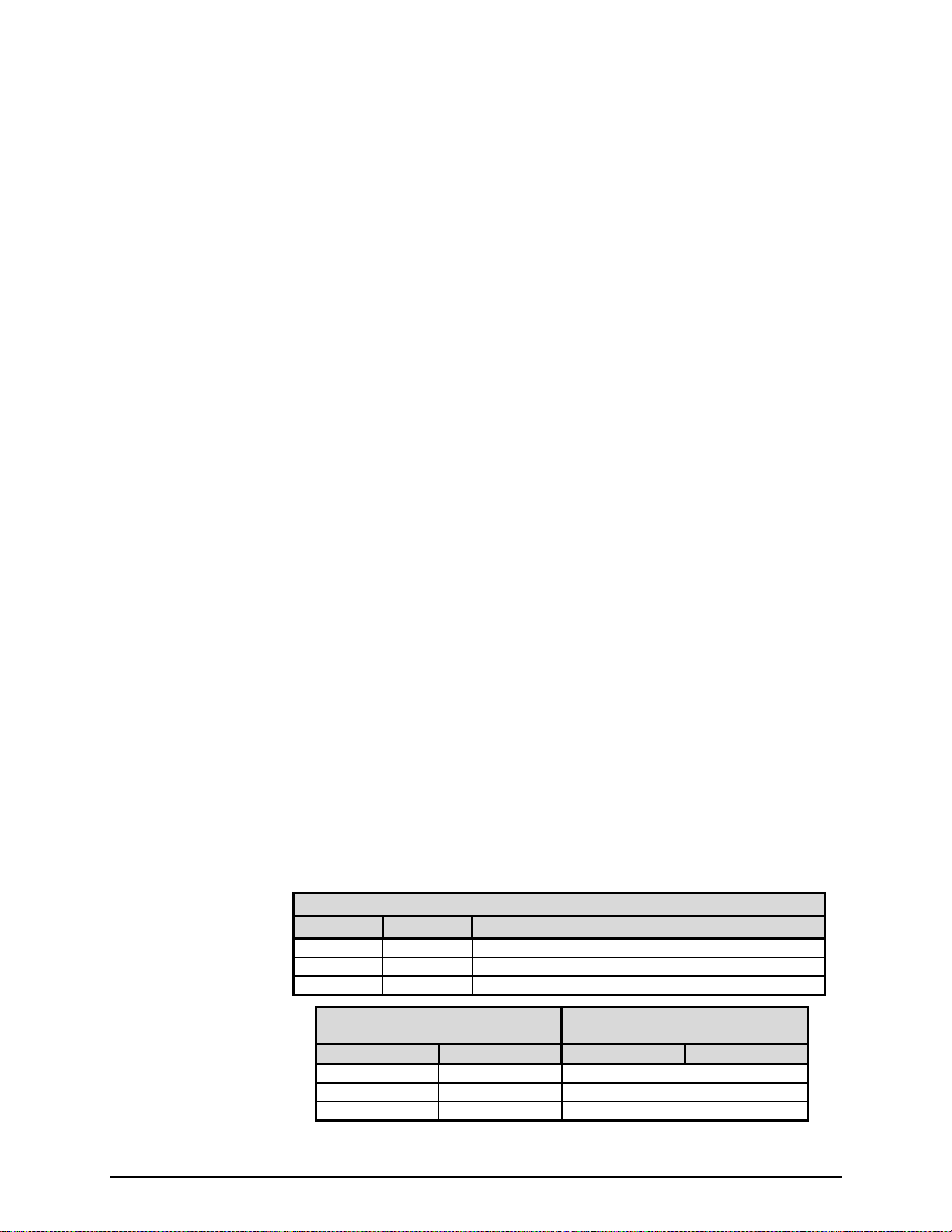
5. Remote Operation
5.1 Overview
Most of the PPC4E front panel functions can also be executed by commands from a remote computer.
The host computer can communicate to the PPC4E using the PPC4E RS232 (COM1) or IEEE-488 ports. The
front panel USB port is used for firmware upgrades only (see Section 6.5). Remote communications via USB
is not supported.
Before writing test code which makes use of PPC4E remote commands, familiarize yourself with its
operating principles by reading Section 3 of this manual. Also refer to Sections 5.2.1.3 and Section
5.2.2.1 for testing RS232 and IEEE-488 commands.
5.2 Remote Interfacing
Sending a program message to the PPC4E places it into Remote mode. The remote indicator below the
the display window lights when the PPC4E is in Remote mode. It will also flicker when a program
message is received. The menus usually accessed from the front panel are locked out while in remote.
[ESC] returns the PPC4E to local operation unless the <REMOTE> command, which locks out all keypad
operation, was sent to the unit.
5.2.1 RS232 Interface
5.2.1.1 COM1
The PPC4E COM1 RS232 interface is located on the back of the unit. It is a 9pin male DB-9F connector configured as a DCE device. Data is transmitted out
of the unit using pin 2, and is received on pin 3. This allows a normal pin-to-pin
DB-9M to DB-9F RS232 cable to be used to connect to a DTE host.
Caution
Handshaking is not required or supported. The COM1 receive
buffer is 255 bytes deep . If the buffer overflows from sending
too much data, the data will be lost. Because of this, it is
essential to send a single program mes sage at a time and it is
essential to wait for the PPC4E to reply to a command before
sending any other command.
Table 15. COM1 Pin Designations and Connections
PPC4E COM1 DB-9F PIN DESIGNATIONS
PIN # FUNCTION DESCRIPTION
2 TxD This pin transmits serial data from the PPC4E to the host.
3 RxD This pin accepts serial data from the host computer.
5 Grn This pin is the common return for the TxD and RxD signals.
IBM PC/XT DB-9F
CONNECTIONS
DB-25M DB-9F DB-9M DB-9F
2 3 3 3
3 2 2 2
7 5 5 5
IBM PC/XT DB-9M TO PPC4E DB9F
CONNECTION
Page 75 © 1998-2010 Fluke Calibration
Find Quality Products Online at: [email protected]
www.GlobalTestSupply.com
Page 84
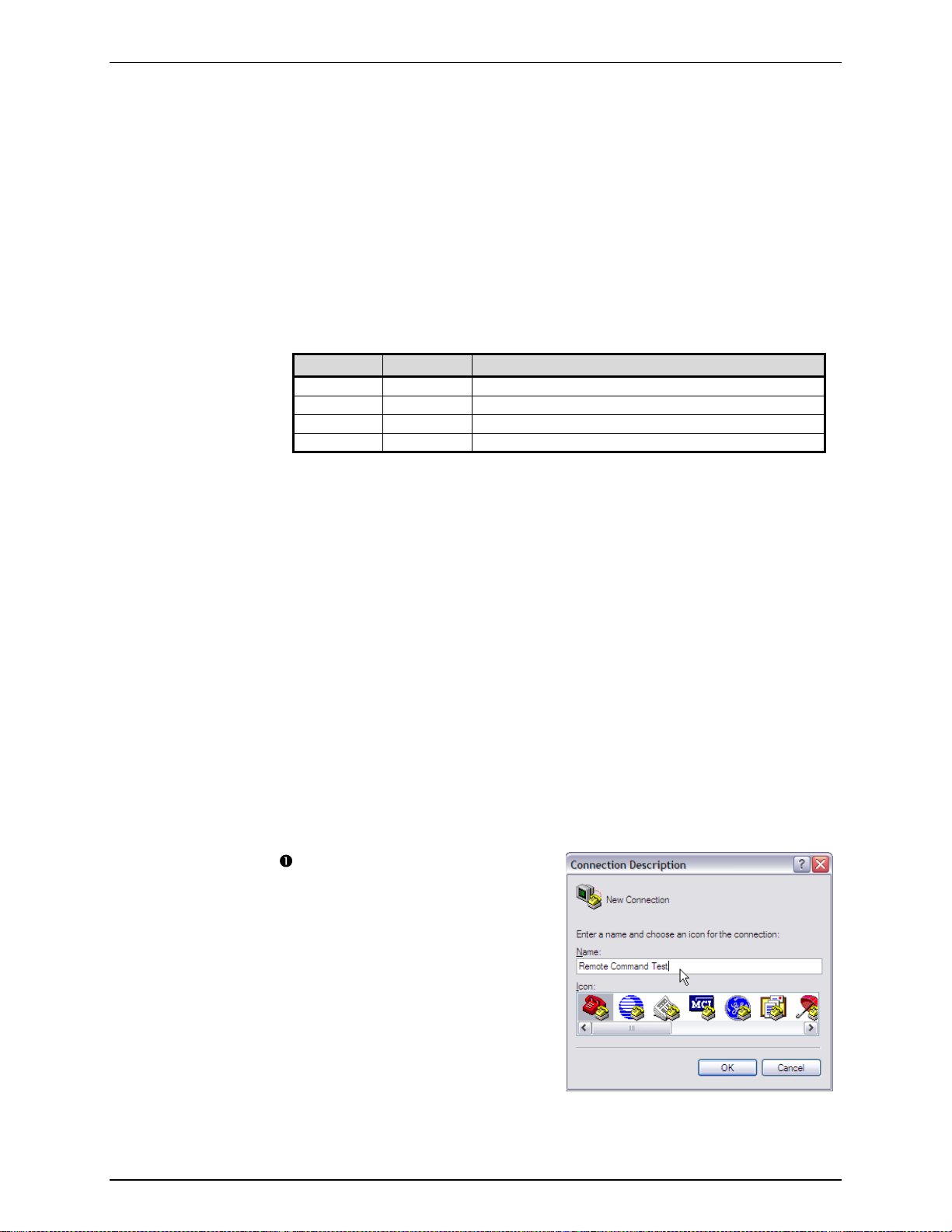
PPC4™ OPERATION AND MAINTENANCE MANUAL
is displayed when
communications session. Future
5.2.1.2 COM2
The PPC4E COM2 RS232 interface is located on the back of the unit. COM2
can be used to allow the host computer to communicate with another device
through the PPC4. This allows the user to use one host COM port to
communicate with the PPC4E and an additional RS232 device. Refer to the “#”
and “PASSTHRU” remote program commands for details.
COM2 is a 9-pin female DB-9F connector configured as a DTE device. Data is
transmitted out of the unit using pin 3, and is received on pin 2. This allows a normal
pin-to-pin DB-9M to DB-9F RS232 cable to be used to connect to a DCE device.
Handshaking is not required or supported.
Table 16. COM2 DB-9F Pin Designations
PIN # FUNCTION DESCRIPTION
2 RxD This pin transmits serial data from the PPC4E to a device.
3 TxD This pin accepts serial data from the external device.
4 DTR This pin is Data Terminal Ready (DTR) (held at + 5 V).
5 Grn This pin is the common return for the TxD and RxD signals.
5.2.1.3 RS232 Command Testing
An easy way to test RS232 communications independent of custom software is
to use the Windows Hyperterminal found in the accessories group under All
Programs (See Figure 11)
Figure 11. Windows selection of Hyperterminal
Hyperterminal must be configured to communicate with the PPC4E using the
RS232 COM1 communication settings accessed through the PPC4E front panel
(see Section 0 for the Advanced Interface and Section Error! Referenc e source
not found. for the Basic Interface). Refer to the following series of steps to
configure Hyperterminal assuming that the PPC4E is connected to COM4 of a
host PC using a baud rate of 2400, 7 data bits, event parity and 1 stop bit.
Figure 12
Hyperterminal is run for the first
time. Enter an easily identifiable
name to reference the
Hyperterminal sessions are initiated
by selecting the named session.
Figure 12. Hyperterminal Initial Display
© 2010 Fluke Calibration Page 76
Find Quality Products Online at: [email protected]
www.GlobalTestSupply.com
Page 85
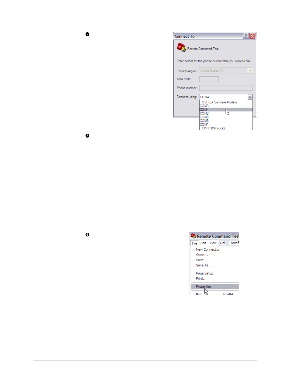
5. REMOTE OPERATION
The next dialog defines the
RS232 port to use for
will be
confuse this selection with the
settings are accessed
RS232 handshaking is not
COM port properties are defined.
define command and response
terminators. Access the [File]
communication. Select the host
PC’s COM port that
connected to the PPC4. Do not
COM1 and COM2 ports on the
back of the PPC4.
After the COM port selection, the
RS232 settings of the PPC4E
must be defined. The specific
PPC4E
through the PPC4E front panel.
supported by the PPC4E,
therefore None is the appropriate
selection for Flow Control.
The focus will return to the main
Hyperterminal program after the
At this point, the last steps are to
menu and select [Properties]
Page 77 © 2010 Fluke Calibration
Find Quality Products Online at: [email protected]
www.GlobalTestSupply.com
Page 86
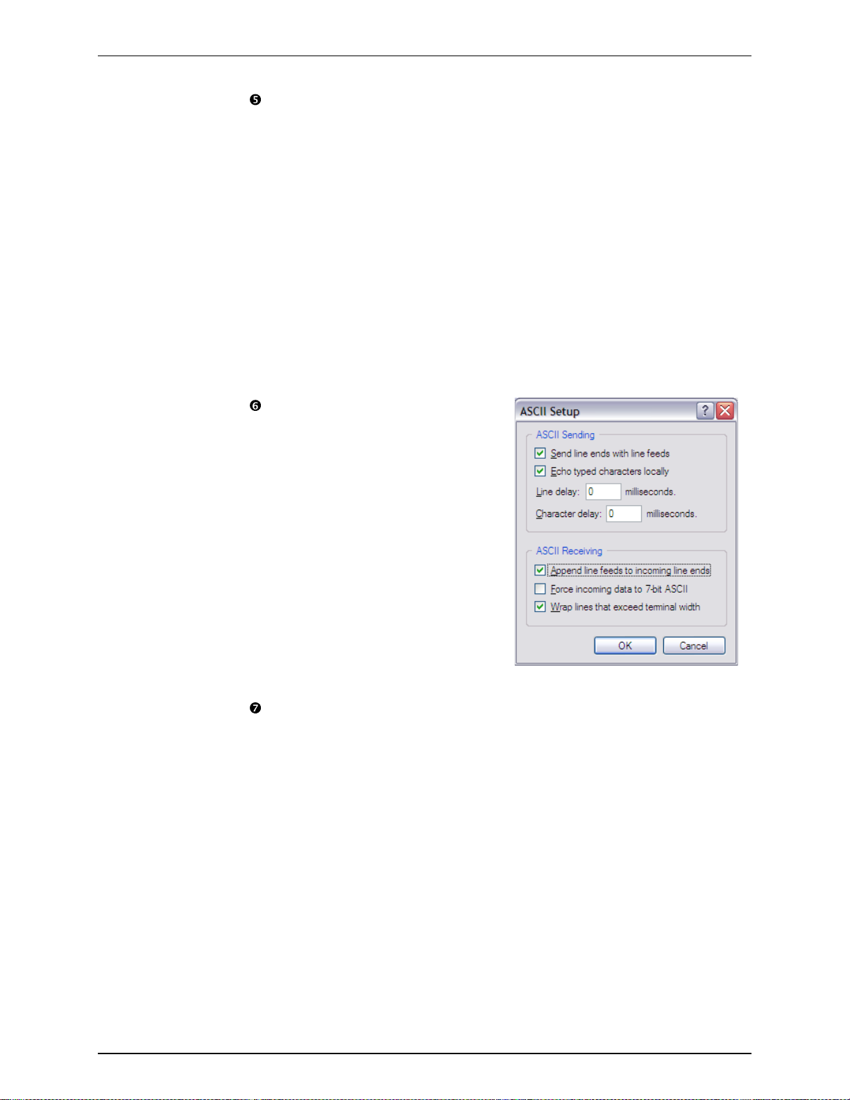
PPC4™ OPERATION AND MAINTENANCE MANUAL
Within the Properties dialog,
appended to the end of the
press the ASCII setup button.
Make the selections listed in the
figure below. These selections
enable a carriage return (ASCII
13) and line feed (ASCII10) to be
commands to the PPC4E and the
corresponding responses. Press
[OK] after the edits are complete.
Figure 13. Hyperterminal ASCII Setup
At this point it is best to save and close the current Hyperterminal session.
Open Hyperterminal a second time, choose [Cancel] on the opening dialog,
then use the [File][Open] menu to select the file just created “Remote
Command testing.
© 2010 Fluke Calibration Page 78
Find Quality Products Online at: [email protected]
www.GlobalTestSupply.com
Page 87
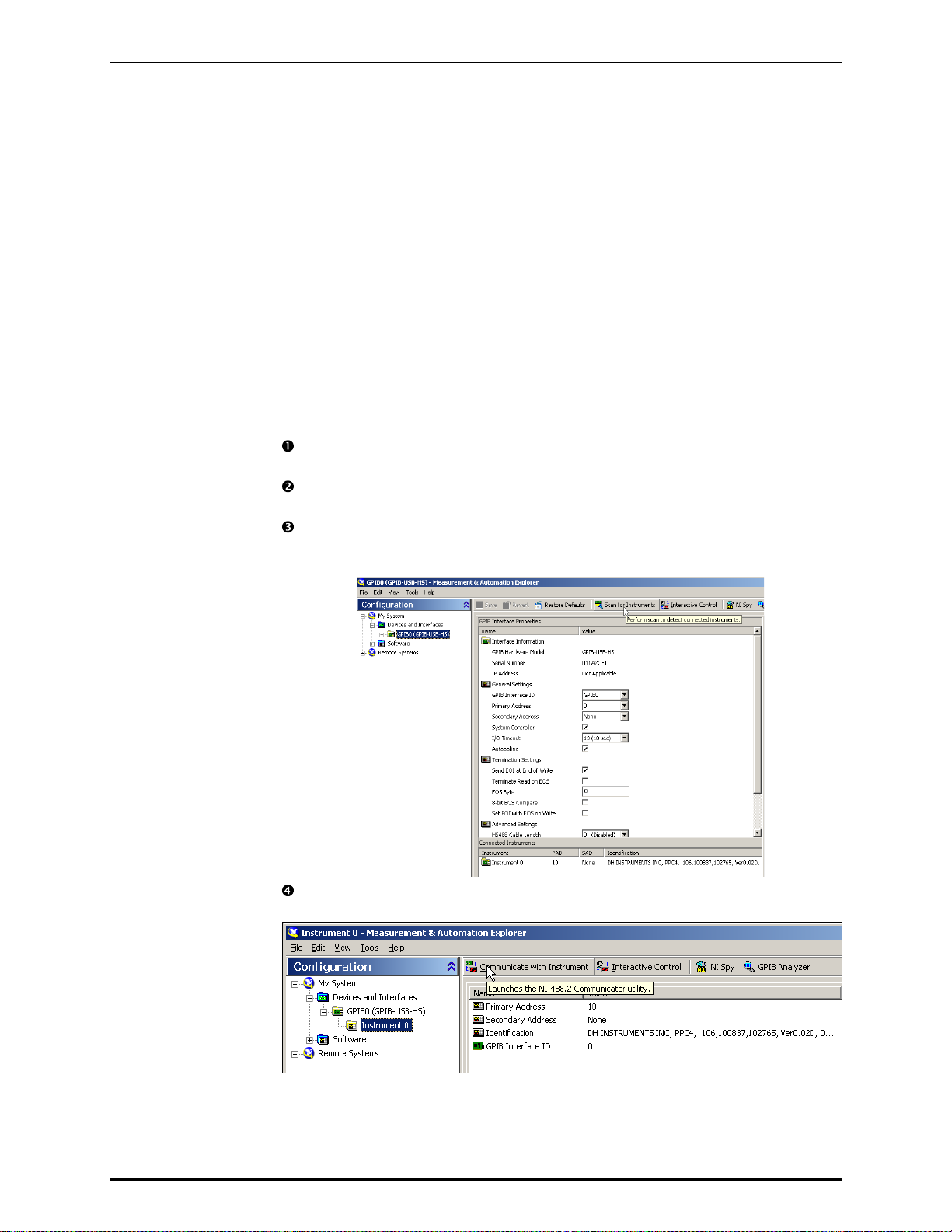
5. REMOTE OPERATION
5.2.2 IEEE-488
The PPC4E IEEE-488 interface is located on the back of the unit. The physical and electrical
interface conforms to IEEE Std 488.1-1987 Subset E2 and IEEE Std. 488.2-1992. Do not
attempt to communicate with the IEEE-488 interface while using the COM1 or USB
interfaces. The IEEE-488 receive buffer is 250 bytes deep. If the buffer overflows, the
PPC4E will hold off release of the NRFD handshake line until it can service and empty the
receive buffer. This keeps the buffer from overflowing. It is recommended that you use the
query form for all remote commands and wait for a reply to each command to ensure proper
operation and order of command execution. Not reading a command response will cause the
PPC4E to respond improperly to future remote commands.
5.2.2.1 IEEE-488 Remote Command testing
Verify IEEE-488 communication with the PPC4E by using a communication tool
provided by the PC‘s IEEE-488 interface manufacturer. The following sequence
describes the steps to setup and communicate with the PPC4E by using a NI
(National Instruments) IEEE-488 adapter. Different versions of the NI adapter
and cards from other manufacturers will have slightly different steps and labeling.
Install the IEEE-488 interface into the host PC and verify that the adapter is
properly setup.
Connect the PPC4E to the host PC by using an IEEE-488 communications
cable.
Launch the NI Measurement and Automation Explorer. Locate the option to
scan for instruments. The PPC4E should be detected at the addressed
defined in [Settings],<Interface>,IEEE-488.
Select the Communicate with Instrument option to invoke a dialog to enter discrete
commands to the PPC4. No other specific PPC4E IEEE-488 setup is required.
Page 79 © 2010 Fluke Calibration
Find Quality Products Online at: [email protected]
www.GlobalTestSupply.com
Page 88
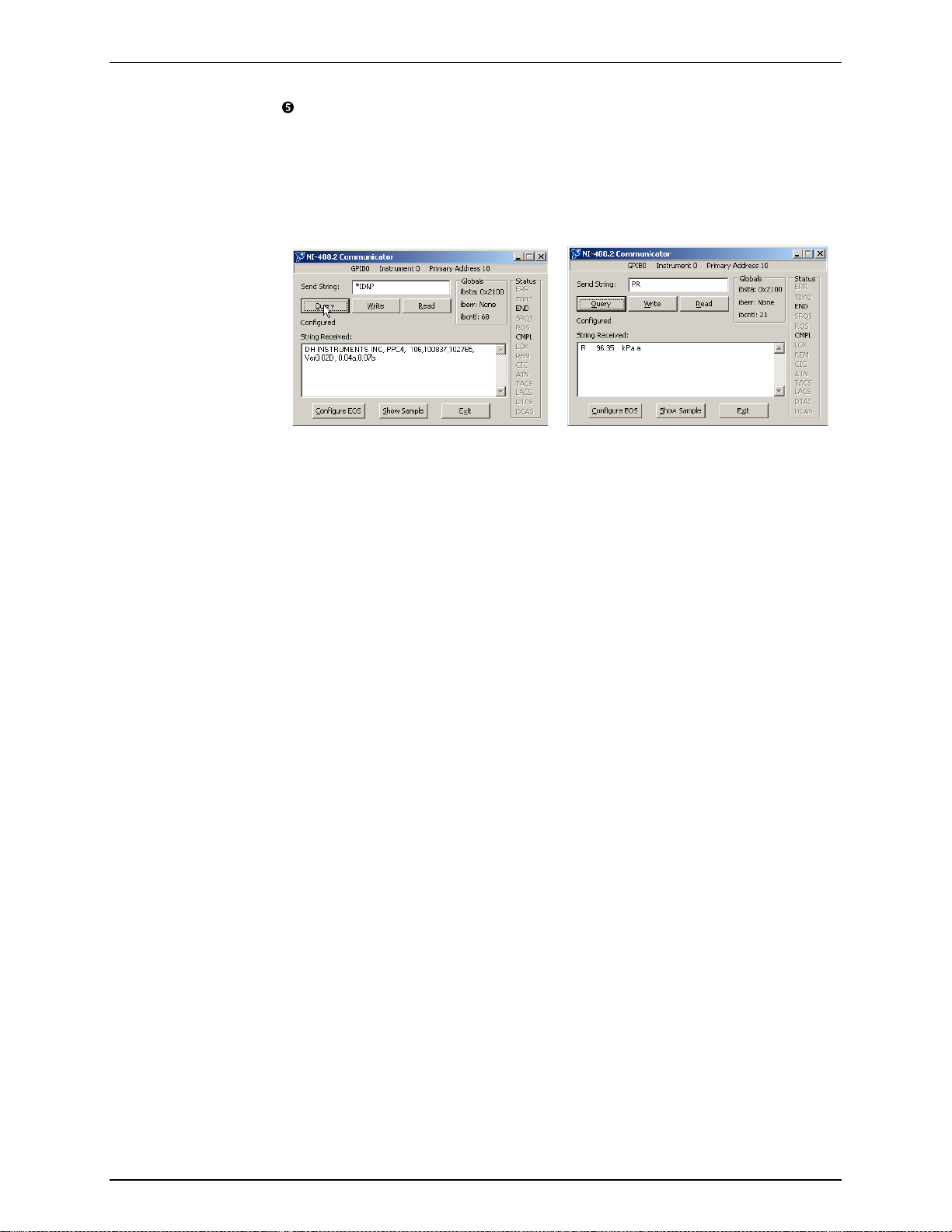
PPC4™ OPERATION AND MAINTENANCE MANUAL
Enter a PPC4E command into the Send String field and choose [Query] or
[Write] based on the command entered and the PPC4E command format.
While communicating in Enhanced mode with IEEE-488, no response is
provided by the PPC4E unless a “?” is included with the command.
Attempting to read a response when a “?” is not included will yield an
interface error. If a “?” is included and a response is not read, future
commands will not respond properly. For this reason, make sure to use the
[Read] button if [Write] was used to send a query form command
5.3 Programming Formats
PPC4E supports two program message formats, “Classic” and “Enhanced”. The user must select which
format to use. Selection can be accomplished from the front panel (see Section 4.7.9.1) or remotely
using the “MSGFMT” program message (see Section 5.4.4).
The main difference between the two formats is that when using the IEEE-488 interface, a “?” must be
included in an enhanced command for there to be a response from the PPC4. In all other cases (classic or
enhanced), every command has a response. In addition, the enhanced message format supports IEEE Std.
488.2 syntax, format and status reporting.
The default is the classic format to allow downward compatibility with existing host software.
In either format, it is recommended that you start out a command sequence with the “*CLS” command,
which clears all of the communication and error queues. The basic commands are similar for both the
classic and enhanced formats, but the usage, syntax, format and status reporting are different.
Note
The PPC4E program message set is compatible with PPC3 and PPC4 program
message sets. In some cases additional arguments are available at the end of
PPC4E commands that are not available in PPC3 commands. However the
command function is not altered.
5.3.1 Classic Program Message Format
Each program message sent is also a query. Only one program message can be sent to the
PPC4E at time. After sending any program message, the PPC4E must reply before another
program message can be sent. The reply will contain data, or a numeric error message if the
program message was invalid. The reply must be received before issuing another program
message to the PPC4. This insures that the PPC4E has completed the program message.
Most remote program messages will return a reply within 500 ms except:
“PR”, “PRR”, “SR”, “ATM”, “RATE”: Up to 2.0 seconds to allow a new measurement.
“RPT”, “ARANGE”: Up to 10 seconds
The syntax and format used for each program message in the classic mode is listed next to
the keyword ‘Classic:’ in each program message summary in Section 5.4.4.
© 2010 Fluke Calibration Page 80
Find Quality Products Online at: [email protected]
www.GlobalTestSupply.com
Page 89

5. REMOTE OPERATION
5.3.2 Enhanced Program Messa ge Form at
The enhanced program message format uses the IEEE Std. 488.2 format, syntax and status
reporting. Errors are reported using the IEEE Std. 488.2 status reporting model. If an error is
reported, the error is put into an Error Queue and the “ERR?” query program message can
be used to get a text description of the most recent error. If you are using the IEEE-488 port,
the service request line can be setup to be asserted if this occurs (see Section 5.5.2). In the
enhanced format, there are two possible program message types for every program
message. Each of these two types starts with the same basic text referred to as the program
message header. The two types are COMMAND type and QUERY type commands.
5.3.2.1 Using Command Type Commands
Note
Enhanced format commands DO NOT reply when using the
IEEE-488 interface unless a “?” is included in the command.
There will be no response from PPC4E to non-query (no “?”)
commands. Remote software can time-out waiting for a
response from PPC4. However, in RS232 communications,
there is always a response and the response MUST be read
prior to issuing another command.
The COMMAND type of program message executes a process and can
additionally send data to the PPC4E in the form of comma delimited arguments.
This data is usually a setting of some sort that is stored in the PPC4. If data is
specified, it must be preceded by at least one white space from the program
message header and be within the range and format described in the program
message description. The keyword “Command:” appears to the left of the
required syntax in each program message description in Section 5.4.4 .
If you are using the IEEE-488 port, the Command type does not generate a reply
unless you place a query operator “?” immediately after the command. You also
may send multiple program messages at once by separating each program
message with a semicolon. The commands are queued and executed in as
received order after the entire message stream has been received, so care in
determining order of execution is needed.
If you are using the RS232 port COM1, the Command type will always generate
a reply so you must wait for a reply before issuing another program message.
Because of this, you can only send one Command program message at a time
while using the COM1 port.
Examples:
• IEEE-488 enhanced mode command series using query opera to r:
“*CLS?” (Clear the error queue. Wait for reply.)
“UNIT? KPA” (Generates a reply. User must wait for reply before continuing.)
“MMODE? A” (Generates a reply. User must wait for reply before continuing.)
“PS? 100” (Generates a reply. User must wait for reply before continuing.)
• IEEE-488 enhanced mode commands without query operator:
“*CLS” (Clear the error queue. No reply.)
“UNIT KPA” (No reply)
“MMODE A” (No reply)
“PS 100” (No reply)
“ERR?” (Wait for reply. User should use “ERR?” query following a
series of non query commands to check for errors that may
have occurred.)
Page 81 © 2010 Fluke Calibration
Find Quality Products Online at: [email protected]
www.GlobalTestSupply.com
Page 90

PPC4™ OPERATION AND MAINTENANCE MANUAL
• IEEE-488 enhanced mode multiple commands without query operator:
“*CLS” (Clear the error queue. No reply)
“UNIT KPA;MMODE A;PS 100” (Three commands at once. No reply)
“ERR?” (Wait for reply. User should use “ERR?”
• COM1 enhanced mode command:
“*CLS” or “*CLS?” (Clear the error queue. Wait for reply.)
“UNIT KPA” or “UNIT? KPA” (Generates a reply. User must wait for
“MMODE A” or “MMODE? A” (Generates a reply. User must wait for
“PS 100” or “PS? 100” (Generates a reply. User must wait for
5.3.2.2 Us ing Query Type Comm ands
The QUERY type of program message just requests data from the PPC4.
Placing the query operator “?” immediately after the command creates a query.
Software must wait for a reply with a query. If any type of program message is sent
to the PPC4E after a query before receiving a reply, the program message will be
discarded and an error will be generated. Errors are reporting using the IEEE
Std. 488.2 status reporting model. A Query program message always ends with
a question mark. Most queries will return a reply within 200 ms except:
“PR?”, “PRR?”, “SR?”, “ATM?”, “RATE?”: Up to 2.0 seconds.
“RPT”, “ARANGE”: Up to 10 seconds
The syntax for using a QUERY program message is listed next to the keyword
“Query:” in each program message summary in Section 5.4.4 .
query following a series of non query
commands to check for errors that may
have occurred)
reply before continuing.)
reply before continuing.)
reply before continuing.)
© 2010 Fluke Calibration Page 82
Find Quality Products Online at: [email protected]
www.GlobalTestSupply.com
Page 91

5. REMOTE OPERATION
5.4 Commands
5.4.1 Programming Messages
Table 17. Program Message List
# Send a command string out of the PPC4E COM2 port.
ABORT Stop pressure generation.
ARANGE Read or set a new AutoRange to use.
ATM Read the current atmospheric pressure (on-board barometer).
AUTOPURGE Read or set the status of the automatic purge function.
AUTOVAC Read or set the status of the control reference (EXHAUST port).
CALAMB Read or set the on-board barometer calibration
COM1 Read or set the configuration of the COM1 port.
COM2 Read or set the configuration of the COM2 port.
DATE Read or set the current date.
DF Decrease the pressure quickly (fast).
DISPUNC Enable or disable display of uncertainty and select the display mode
DP Decrease the pressure a given amount.
DRV Read or set the status of the external valve drivers.
DS Decrease pressure slowly.
ERR Read the last error message.
GPIB Read or set the GPIB interface address.
HEAD Read or set the fluid head settings.
HS Read or set the current control hold limit in pressure.
HS% Read or set the current control hold limit in percent span of the active range.
ID Read or set the PPC4E alphanumeric asset ID tag.
IF Increase the pressure quickly (fast).
IP Slowly increase the pressure a given amount.
IS Increase the pressure slowly.
Ln Gets or sets the command interpreter mode.
LAN Read or set the optional network interface settings.
LL Read or set the lower limit for the current range (negative gauge mode only).
LOCAL Return control to the PPC4E front panel.
MEM Read the power-up memory test status.
MMODE Read or change the active measurement mode.
MODE Read or set the current pressure control mode.
MSGFMT Read or set the type of program message format to use.
NVENT Read or set the status of the lo vent valve (Gxxx or BGxxx RPT only).
PASSTHRU Send a command string out of the PPC4E COM2 port.
PCAL:IH Read or set the user Lo RPT calibration information.
PCAL:IL Read or set the user Hi RPT calibration information.
PR Read the next PPC4E pressure.
PRR
PS Set a new target pressure and start automated pressure control.
PSF Set a new target pressure and use only the fast speed to reach the target.
PSS Set a new target pressure and use only the slow speed to reach the target.
QPRR
Read the next available pressure, rate, on-board barometer reading, control status, and
the QRPT uncertainty.
Quickly read the last known pressure, rate, on-board barometer reading, control status
and QRPT uncertainty.
Page 83 © 2010 Fluke Calibration
Find Quality Products Online at: [email protected]
www.GlobalTestSupply.com
Page 92

PPC4™ OPERATION AND MAINTENANCE MANUAL
UDU
VAC
ZOFFSETn
RANGE Read or set and RPT or utility sensor default range (PPC4E command).
RATE Read the next available rate of change of pressure.
READYCK Read or set a flag that is cleared by a Not Ready condition.
REMOTE Enable remote local lockout operation.
RES Read or set the pressure display resolution for the current transducer and range.
RESET Reset the PPC4E to the default user parameters.
RETURN Start a new automated pressure control set using the current target value.
RPT Read the available RPT data or initiate the RPT search process.
SCRSAV Read or set the front panel display screen saver activation time & type.
SN Read the serial number of the PPC4.
SR Read the next available pressure status (Ready/Not Ready).
SS Read or set the stability required for a Ready condition.
SS% Read or set the stability required for a Ready condition (% span/ s).
STAT Read the pressure control status.
TIME Read or set the current time of day.
TIMEFMT Read or set the clock time format.
TP Read the current target pressure.
UCOEF Convert a pressure in Pascal to pressure in the current units.
Read or set the user defined pressure unit.
UL Read or set the upper limit for the current range.
UNIT Read or set the pressure unit of measure for the current range.
Read or set the exhaust reference status flag.
VENT Read, execute or abort a vent process.
VER Read the PPC4E software version.
Read or set the AutoZero P
for the specified RPT.
offse t
© 2010 Fluke Calibration Page 84
Find Quality Products Online at: [email protected]
www.GlobalTestSupply.com
Page 93

5. REMOTE OPERATION
ERR# 3
“Arguments cannot be 0”
ERR# 7
“Missing or improper command argument(s)”
ERR# 14
“User unit not defined”
ERR# 20
“Not available with gauge device”
ERR# 22
“Pressure is not stable”
ERR# 26
“COM port failed to initialize”
ERR# 28
“Device failure”
ERR# 38
“Selected range is not available”
ERR #52
“Command obsolete”
5.4.2 Error Messages
Table 18. Error #s and Descriptions
REPLY DESCRIPTION
ERR# 0 “OK”
ERR# 2 “Text argument is too long”
ERR# 6 “Numeric argument missing or out of range”
ERR# 9 “Unknown command”
ERR# 10 “Missing or invalid command suffix”
ERR# 11 “Command missing argument”
ERR# 12 “System overpressured” or “overpressure may result”
ERR# 13 “Text queue overflow”
ERR# 16 “Generation failure”
ERR# 18 “Command not yet available”
ERR# 19 “Not available with absolute units”
ERR# 21 “User device not defined”
ERR# 23 “Option not available or installed”
ERR# 24 “Unit must be vented”
ERR# 25 “Transducer out of calibration”
ERR# 27 “Internal device failure”
ERR# 29 “Device not available”
ERR# 30 “Must be on range IH”
ERR# 31 “Exceeds upper or lower limit”
ERR# 32 “Not stable enough”
ERR# 37 “Data table is full”
ERR# 39 “Data verify error”
ERR# 45 “Argument not allowed”
ERR #46 “Argument cannot be negative”
ERR# 53 “Not Available”
Page 85 © 2010 Fluke Calibration
Find Quality Products Online at: [email protected]
www.GlobalTestSupply.com
Page 94

PPC4™ OPERATION AND MAINTENANCE MANUAL
5.4.3 Program Message Description Overview
Each program message description is separated into the following sections:
Purpose A brief description of the programs message’s function.
Command
Query
Classic
Arguments
Default
Remarks This field has the details and remarks about the command.
Example Examples are given for the enhanced and classic methods.
Errors
See Also Indicates related command (“----“) and refers to manual sections giving detail on PPC4E
This is the Enhanced program message syntax to send data to the PPC4E or to execute
a PPC4E function. The PPC4E must be set to use the enhanced format (see Section
3.5.2.3) to use the syntax and style shown. It may be sent alone, or followed by at least
one white space and additional argument(s) to show that arguments can be passed. If
there are multiple arguments, then commas must separate them. If you are using the
IEEE-488 port, multiple command type program messages can be sent in one message if
you separate them with a semicolon. There will be no reply from the PPC4E using the
IEEE-488 port unless the command is immediately followed by the query operator “?”. If
you are using the COM1 port, the PPC1 will reply and you must wait for this reply. If this
field is not listed in the program message description, then the Command type is not
supported when using the Enhanced format.
This is the Enhanced program message syntax to request data from the PPC4. The
PPC4E must be set to use the enhanced format (see Section 3.5.2.3). The PPC4E will
always reply to a query. You must wait for this reply before issuing another program
message. If this field (Query) is not listed in the program message description, then the
Query type for the program message is not supported when using the Enhanced format.
This is the Classic program message syntax to send data to the PPC4E, to execute a
PPC4E function, or to query for data. The PPC4E must be set to use the classic format
(see Section 3.5.2.3).
The command may be followed by a ‘(=)’ and additional argument characters to show that
argument(s) can be passed. If there are multiple arguments, then commas must separate
them. The PPC4E will always reply to a Classic program message. You must wait for
this reply before issuing another program message. If this field is not listed in the
program message description, then it is not supported when using the classic format.
If the program message can be used to set data inside the PPC4E, then this section
describes the arguments and their limits. Command arguments that reference the terms
“IH” and “IL” refer to the PPC4E Hi and Lo RPT respectively.
If the program message can be used to set data inside the PPC4E, then this line shows
(using the enhanced format) the default setting from the factory.
Enhanced: An example of the use of an enhanced format program message to be sent
to the PPC4E is shown. The message sent to the PPC4E appears after the
“Cmd sent:” label. If only a Query type exists, the “Query sent:” label is
shown instead. Directly under this label, “Query reply” shows a typical
reply to a query type. “Reply:” shows that a query format does not exist.
It may have a short description next to it.
Classic: An example of the use of a classic program message to be sent to the
PPC4E is shown. The command sent to the PPC4E appears after the
“Cmd sent:” label. The “Reply” label shows a typical reply to the “Sent”
example.
It may have a short description next to it.
If the program message can report an argument error, the types of errors are listed.
If using the classic format or the COM1 port, the error message is replied after receiving
the program message. If using the enhanced format via the IEEE-488 port, the error
condition is handled by the status reporting model which stores the errors in an Error
Queue and can be programmed to assert the IEEE-488 SRQ line to signal an error has
occurred. In either case, the “ERR” or “ERR?” program message can be used to
retrieve a text description of the error.
operation corresponding to the program message.
© 2010 Fluke Calibration Page 86
Find Quality Products Online at: [email protected]
www.GlobalTestSupply.com
Page 95

5. REMOTE OPERATION
5.4.4 Program Message Descriptions
#
Purpose
Classic “#xx”
Arguments xx:
Remarks
Example
(classic)
See Also “PASSTHRU”, “COM2”
ABORT
Purpose
Command
Classic
Remarks
Example
(enhanced)
Example
(enhanced)
Example
(classic)
See Also 3.2.11, 3.2.2
To allow the host PC to communicate with a device connected to the PPC4E COM2 port.
The preferred method is to use the “PASSTHRU” program message.
The string to send out of the COM2 port. It must be less than
40 characters long.
The PPC4E COM2 port can be used to communicate to another RS232 device (such as
another PPC4). This allows the user to use one COM port or IEEE-488 port on the host
computer to communicate with the PPC4E and another device. A carriage return and a
line feed (<CR><LF>) are added to the string.
After this program message is issued, the PPC4E will reply back the first string received
by the PPC4E COM2 port that is terminated with a carriage return. Line feeds are
discarded.
This will discontinue when the next program message is sent to the PPC4.
There is no other reply from this program message. Prior to using this program message,
you must ensure that the PPC4E COM2 port is correctly set up to communicate with the
device on COM2. Refer to the “COM2=“ program message.
Sent:
Reply:
This example assumes that a second PPC4E’s COM1 port is connected to the PPC4E
COM2 port. This example gets the version of the second PPC4.
3.2.22
Stops active pressure generation/control. All control valves are closed. The exhaust and
transducer isolation valves are not affected.
“ABORT”
“ABORT”
This program message has no effect if the PPC4E is not using automated pressure
control. When using automated pressure control, it aborts the control. This command is
recommended to idle the PPC4E before setting a new target pressure.
Cmd sent:
Reply:
Cmd sent:
Reply:
Sent:
Reply:
“#VER”
“FLUKE PPC4E us A1000/A0015 Ver2.00 ”
“ABORT”
“ABORT” (no reply if IEEE-488)
“ABORT?”
“ABORT”
“ABORT”
“ABORT”
Page 87 © 2010 Fluke Calibration
Find Quality Products Online at: [email protected]
www.GlobalTestSupply.com
Page 96

PPC4™ OPERATION AND MAINTENANCE MANUAL
ARANGE
Purpose
Read existing AurtoRange range or create a new AutoRange range.
Query
“ARANGE?”
“ARANGE”
Range
The AutoRange maximum pressure. Cannot be negative.
Unit:
The unit of measure of the Range argument.
“IL”: Lo RPT
temperature reference in the reply.
(enhanced)
Query reply:
“100.00, psi, A, IH”
(classic)
Query reply:
“100.00, psi, A, IH”
ERR# 29:
Correct type of RPT for the selected “Mode” is not available.
ATM
Command
“ARANGE Range, unit, mode (,RptLabel)”
Classic “ARANGE= Range, units, mode (,RptLabel)”
Arguments
Mode: The measurement mode of the Range argument:
“A” for absolute
“G” for gauge
“N” for negative gauge
Note
Measured pressure values are returned with “g” to
identify measurement mode for both gauge and negative
gauge measurement modes.
RptLabel:
(optional)
Remarks The ARANGE command is used to define a PPC4E range by specifying a desired unit of
measure, measurement mode and maximum pressure, and have the PPC4E pick the
best available RPT and make operational adjustments to optimize that range. Available RPTs
may be determined by the use of the “RPT” command or [RPT] function key.
The reply indicates the current range data, including the RptLabel used for the range.
If a water column unit (inH2O, mH2O, mmH2O) is specified for the pressure unit of
measure, the temperature reference can be given after the unit text. For example,
“inH2O4”, “inH2O20” or “inH2O60” corresponds to inH2O at 4 °C, 20 °C or 60 °F. If no
temperature is specified, a default of 20 °C is assumed. There is no indication of the
One of the RPTs that is available.
“IH”: Hi RPT
Example
Example
Example
(enhanced)
Example
(classic)
Errors ERR# 6:
Cmd sent:
Cmd sent:
Cmd sent:
Query reply:
Cmd sent:
Query reply:
ERR# 19:
ERR# 20:
“ARANGE?” (read the current range in the current units)
“ARANGE” (read the current range in the current units)
“ARANGE? 250, inWa4, G (range of 250 inWa @ 4 °C in gauge mode)
“250.000 inWa, G, IH” (Hi RPT)
“ARANGE=250, kPa, G (set a range of 250 kPa in gauge mode)
“250.00 kPa, G, IL” (Lo RPT)
“Range“ maximum pressure exceeds available RPTs or is negative.
Cannot Range to ‘0’ with absolute units.
Cannot Range to ‘0’ with gauge units.
See Also “RPT”, “RANGE”
Error! Reference source not found.. 3.2.5, 3.2.6, 3.2.10
Purpose Reads the next measured pressure from PPC4E’s on-board barometer.
Query
Classic
Remarks
“ATM?”
“ATM”
The atmospheric pressure as measured by the PPC4E on-board barometer is returned in
the current pressure units (always absolute). This measurement is followed by the units
text.
Example
(enhanced)
Example
(classic)
Query sent:
Query reply:
Sent:
Reply:
“ATM?”
“97.12348 kPaa”
“ATM”
“97.12384 kPaa”
See Also 3.2.25.3
© 2010 Fluke Calibration Page 88
Find Quality Products Online at: [email protected]
www.GlobalTestSupply.com
Page 97

5. REMOTE OPERATION
AUTOPURGE
AUTOVAC
Purpose Read or set the status of the automatic purge function.
Command
Query
Classic “AUTOPURGE=n”
Default “AUTOPURGE 0”
Arguments n: ’0’ To disable AUTO mode.
Remarks
Example
(enhanced)
Example
(enhanced)
Example
(classic)
Errors ERR# 6: The argument was other than a ‘0’ or a ‘1’.
See 3.2.16, 3.2.25.4
Purpose Read or set the status of the automated Control Ref determination mode.
Command
Query
Classic “AUTOVAC=n”
Default “AUTOVAC 1”
Arguments n: ’0’ To disable AUTO mode. (“VAC” cmd determines status)
Remarks
Example
(enhanced)
Example
(enhanced)
Example
(classic)
Errors ERR# 6: The argument was other than a ‘0’ or a ‘1’.
See Also “VAC”
“AUTOPURGE n”
“AUTOPURGE?”
“AUTOPURGE”
’1’ To enable AUTO mode.
The PPC4E can automatically control the external SPLT functions to purge the test
system before running a test, if desired.
Cmd sent:
Query reply:
Cmd sent:
Query reply:
Sent:
Query reply:
“AUTOPURGE 1”
“1” (No reply if IEEE-488)
“AUTOPURGE 1”
“1”
“AUTOPURGE=1”
“AUTOPURGE=0”
“AUTOVAC n”
“AUTOVAC?”
“AUTOVAC”
’1’ To enable AUTO mode. This will override the manual selection.
At low pressures, PPC4E control is affected by whether the EXHAUST port is open to
atmosphere or connected to vacuum. The PPC4E has an internal sensor that can be
used to automatically determine if the EXHAUST port is open to atmosphere or to a
vacuum. You can disable it to manually override it. It is recommended to use the “VAC”
command to disable this feature instead of the “AUTOVAC=0” command, as you can also
specify vacuum or atmospheric reference at the same time with the VAC command.
Cmd sent:
Query reply:
Cmd sent:
Query reply:
Sent:
Query reply:
“AUTOVAC 1”
“1” (No reply if IEEE-488)
“AUTOVAC 1”
“1”
“AUTOVAC=0”
“AUTOVAC=0”
3.2.25.2
Page 89 © 2010 Fluke Calibration
Find Quality Products Online at: [email protected]
www.GlobalTestSupply.com
Page 98

PPC4™ OPERATION AND MAINTENANCE MANUAL
CALAMB
COM1
Purpose Read or set the on-board barometer calibration coefficients.
Command
Query
Classic “CALAMB=adder, mult, CalDate”
Defaults “CALAMB = 0.0, 1.0, 19800101”
Arguments Adder: The Barometer calibration adder (PA).In Pascal.
Mult: The Barometer calibration multiplier (PM) from 0.1 to 100.
CalDate: The date of the calibration in the format “YYYYMMDD”
Remarks
Example
(enhanced)
Example
(classic)
Errors ERR# 6: One of the arguments is out of range.
See Also 3.2.25.3, 6.3
Purpose Read or set the RS232 settings for the COM1 port.
Command
Query
Classic “COM1=baud, parity , dat a, stop”
Arguments Baud: The baud rate. This may be ’2400’,’4800’, ‘9600’ or ‘19200’.
Parity: The data parity. This may be ‘O’ for odd, ‘E’ for even, or ‘N’ for none.
Data: The number of data bits. This may be ‘7’ or ‘8’.
Stop: The number of stop bits. This may be ‘1’ or ‘2’.
Defaults “COM1 2400,E,7,1”
Remarks
Example
(enhanced)
Example
(enhanced)
Example
(classic))
Errors ERR# 7: Missing or improper program message argument(s).
See Also “PASSTHRU”
“CALAMB adder, mult, CalDate”
“CALAMB?”
“CALAMB”
The barometer calibration information can be accessed with this program message. Using
this program message overwrites the current calibration coefficients, so caution must be
used. Changes made take effect immediately.
Cmd sent:
Query reply:
Sent:
Reply:
“CALAMB? 2.1, 1.000021, 20011201”
“ 2.10, 1.000021, 20011201” (No reply if IEEE-488)
“CALAMB=2.1, 1.000021, 20011201”
“ 2.1, 1.000021, 20011201”
“COM1 baud, parity, data, stop”
“COM1?”
“COM1”
The COM1 port is used to communicate to the PPC4. When the COM1 port configuration of
the PPC4E is changed, the program message reply (COM1 use only) is sent at the old COM1
settings, but all subsequent communications are accomplished at the new COM1 settings.
A 200ms or longer delay after receiving the reply to this command will ensure that the
PPC4E has changed the COM port settings and is ready for communications at the new
settings.
Cmd sent:
Query reply:
Cmd sent:
Query reply:
Sent:
Reply:
“COM1 9600,N,8,1”
“9600,N,8,1” (No reply if IEEE-488)
“COM1? 9600,N,8,1”
“9600,N,8,1”
“COM1=9600,N,8,1”
“9600,N,8,1”
3.2.22
© 2010 Fluke Calibration Page 90
Find Quality Products Online at: [email protected]
www.GlobalTestSupply.com
Page 99

5. REMOTE OPERATION
DATE
COM2
Purpose Read or set the RS232 settings for the COM2 port.
Command
Query
“COM2 baud,parity,data,stop”
“COM2?”
Classic “COM2= baud,parity,data,stop”
“COM2”
Arguments baud: The baud rate. This may be ’2400’,’4800’, ‘9600’ or ‘19200’.
parity: The data parity. This may be ‘O’ for odd, ‘E’ for even, or ‘N’ for none.
Data: The number of data bits. This may be ‘7’ or ‘8’.
stop: The number of stop bits. This may be ‘1’ or ‘2’.
Defaults “COM2 2400,E,7,1”
Remarks
The COM2 port can be used to allow the host computer to communicate through the PPC4E
to an additional device connected to COM2. This can be useful if the host computer does not
have 2 serial ports available.
Example
(enhanced)
Example
(enhanced)
Example
(classic)
Cmd sent:
Query reply:
Cmd sent:
Query reply:
Sent:
Reply:
“COM2 9600,N,8,1”
“9600,N,8,1” (No reply if IEEE-488)
“COM2? 9600,N,8,1”
“9600,N,8,1”
“COM2=9600,N,8,1”
“9600,N,8,1”
Errors ERR# 7: Missing or improper program message argument(s).
See Also “#”, “PASSTHRU”
3.2.22
Purpose Read or set the PPC4E date.
Command
Query
“DATE date”
“DATE?”
Classic “DATE= date”
“DATE”
Arguments date: The date in the numerical only format YYYYMMDD.
Remarks
The PPC4E has an internal real time calendar clock. It is used for date stamping calibrations.
The reply is always in the YYYYMMDD format.
Example
(enhanced)
Example
(enhanced)
Cmd sent:
Query reply:
Cmd sent:
Query reply:
“DATE 20030115”
“20030105” (No reply if IEEE-488)
“DATE? 20030105”
“20020105”
Errors ERR# 7: Missing or improper program message argument(s).
See Also “TIME”
3.2.24.3
DF
Purpose Decrease the pressure quickly (fast).
Command “DF n”
Classic “DF=n”
Arguments ‘0’
‘1’
Closes the fast down valve.
Opens the fast down valve.
Remarks Opening the fast down valve causes the pressure to decrease quickly.
Example
(enhanced)
Example
(enhanced)
Example
(classic)
Cmd sent:
Reply:
Cmd sent:
Reply:
Sent:
Reply:
“DF 1”
“1” (no reply if IEEE-488)
“DF? 1”
“1”
“DF=1”
“DF=1”
Errors ERR# 6: The n argument is a ‘0’ or a ‘1’.
See Also “IF” , “DS”, “IS”, “IP”, “DP”,
Figure 17
Page 91 © 2010 Fluke Calibration
Find Quality Products Online at: [email protected]
www.GlobalTestSupply.com
Page 100

PPC4™ OPERATION AND MAINTENANCE MANUAL
DISPUNCn
DP
DRVn
DS
Purpose Read or set the RPT uncertainty display mode.
Command
Query
Classic “DISPUNCn=Enable, Mode”
Defaults “DISPUNCn = 1, 1”
Suffix n: ‘1’ to access the IH RPT settings
Arguments Enable: ’0’ or ‘1’ to disable or enable the uncertainty display.
Mode: ‘0’ or ‘1’ to display measured ro delivered pressure uncertainty (optional).
Remarks
Example
(enhanced)
Example
(classic)
Errors ERR# 6: One of the arguments is out of range.
See Also 3.2.27
Purpose Decrease the pressure slowly a given amount using the slow speed.
Command “DP n”
Classic “DP=n”
Arguments n:
Remarks
Example
(enhanced)
Example
(enhanced)
Example
(classic)
Errors ERR# 6: The n argument is not within given limits.
See Also “IP”, “DS”, “IS”, “DF”, “IF”
“DISPUNCn Enable, Mode”
“DISPUNCn?”
“DISPUNCn”
‘2’ to access the IL RPT settings
The Mode argument is optional, so that the display can be enabled or disabled without
changing the mode.
Cmd sent:
Query reply:
Sent:
Reply:
“DISPUNC 1, 1”
“1, 1” (No reply if IEEE-488)
“DISPUNC=0”
“0, 1”
The decrease in pressure desired (current pressure units). This can be from
0 to 2 % FS of the active range.
The slow speed will be used for a calculated amount of time (up to 5 seconds) to create the desired
change. The PPC4E will not attempt to control the pressure to a target, so the change in pressure
will be approximate. This is the equivalent of using .
Cmd sent:
Reply:
Cmd sent:
Reply:
Sent:
Reply:
“DP 2”
“2.000 kPa” (no reply if IEEE-488)
“DP? 2”
“2.000 kPa”
“DP=2”
“2.000 kPa”
3.2.1
Purpose Read or set the status of external electrical drivers.
Command
Query
“DRVn x”
“DRVn?”
Classic “DRVn=x”
“DRVn”
Arguments n:
x:
Remarks
The PPC4E control has eight optional external drivers. Driver is used by the optional Purge
The driver to operate. This can be from 1 to 8.
The state to change the driver to; ‘0’ to de-activate it, ‘1’ to activate it.
function.
Example
(enhanced)
Example
(enhanced)
Example
(classic)
Cmd sent:
Query reply:
Cmd sent:
Query reply:
Sent:
Reply:
“DRV1 1”
“1” (No reply if IEEE-488)
“DRV2? 1”
“1”
“DRV1=1”
“DRV1=1”
Errors ERR# 6: The n or x arguments are not within given limits.
See Also 3.2.21
Purpose Decrease the pressure slowly.
© 2010 Fluke Calibration Page 92
Find Quality Products Online at: [email protected]
www.GlobalTestSupply.com
 Loading...