

Page 1

Via Acquanera, 29 22100 Como
tel. 031.526.566 (r.a.) fax 031.507.984
[email protected] www.calpower.it
4322
Automated Pressure Calibrator
Reproduction and distribution of this technical
manual is authorized for U.S. Government purposes.
PN 4133206
September 2013
© 2013 Fluke Corporation. All rights reserved. Specifications are subject to change without notice.
All product names are trademarks of their respective companies.
Operat
ors Manual
Page 2

LIMITED WARRANTY AND LIMITATION OF LIABILITY
Each Fluke product is warranted to be free from defects in material and workmanship under normal use and
service. The warranty period is one year and begins on the date of shipment. Parts, product repairs, and
services are warranted for 90 days. This warranty extends only to the original buyer or end-user customer of
a Fluke authorized reseller, and does not apply to fuses, disposable batteries, or to any product which, in
Fluke's opinion, has been misused, altered, neglected, contaminated, or damaged by accident or abnormal
conditions of operation or handling. Fluke warrants that software will operate substantially in accordance
with its functional specifications for 90 days and that it has been properly recorded on non-defective media.
Fluke does not warrant that software will be error free or operate without interruption.
Fluke authorized resellers shall extend this warranty on new and unused products to end-user customers
only but have no authority to extend a greater or different warranty on behalf of Fluke. Warranty support is
available only if product is purchased through a Fluke authorized sales outlet or Buyer has paid the
applicable international price. Fluke reserves the right to invoice Buyer for importation costs of
repair/replacement parts when product purchased in one country is submitted for repair in another country.
Fluke's warranty obligation is limited, at Fluke's option, to refund of the purchase price, free of charge repair,
or replacement of a defective product which is returned to a Fluke authorized service center within the
warranty period.
To obtain warranty service, contact your nearest Fluke authorized service center to obtain return
authorization information, then send the product to that service center, with a description of the difficulty,
postage and insurance prepaid (FOB Destination). Fluke assumes no risk for damage in transit. Following
warranty repair, the product will be returned to Buyer, transportation prepaid (FOB Destination). If Fluke
determines that failure was caused by neglect, misuse, contamination, alteration, accident, or abnormal
condition of operation or handling, including overvoltage failures caused by use outside the product’s
specified rating, or normal wear and tear of mechanical components, Fluke will provide an estimate of repair
costs and obtain authorization before commencing the work. Following repair, the product will be returned to
the Buyer transportation prepaid and the Buyer will be billed for the repair and return transportation charges
(FOB Shipping Point).
THIS WARRANTY IS BUYER'S SOLE AND EXCLUSIVE REMEDY AND IS IN LIEU OF ALL OTHER
WARRANTIES, EXPRESS OR IMPLIED, INCLUDING BUT NOT LIMITED TO ANY IMPLIED WARRANTY
OF MERCHANTABILITY OR FITNESS FOR A PARTICULAR PURPOSE. FLUKE SHALL NOT BE LIABLE
FOR ANY SPECIAL, INDIRECT, INCIDENTAL, OR CONSEQUENTIAL DAMAGES OR LOSSES,
INCLUDING LOSS OF DATA, ARISING FROM ANY CAUSE OR THEORY.
Since some countries or states do not allow limitation of the term of an implied warranty, or exclusion or
limitation of incidental or consequential damages, the limitations and exclusions of this warranty may not
apply to every buyer. If any provision of this Warranty is held invalid or unenforceable by a court or other
decision-maker of competent jurisdiction, such holding will not affect the validity or enforceability of any other
provision.
Fluke Corporation
P.O. Box 9090
Everett, WA 98206-9090
U.S.A.
11/99
Fluke Europe B.V.
P.O. Box 1186
5602 BD Eindhoven
The Netherlands
To register your product online, visit register.fluke.com
Page 3

Table of Contents
Chapter Title Page
1 Product Overview and Specifications ............................................... 1-1
Introduction ........................................................................................................ 1-3
Product Overview .............................................................................................. 1-3
Safety Information ............................................................................................. 1-4
The Product Manual Set .................................................................................... 1-5
Contact Fluke Calibration .................................................................................. 1-5
Calibration and Repair Information ................................................................... 1-6
Unpacking .......................................................................................................... 1-6
Controller Indicators and Controls ..................................................................... 1-7
Handheld Control Indicators and Controls ........................................................ 1-11
Pressure Intensifier Indicators and Controls ...................................................... 1-13
Accessory Kit Items ........................................................................................... 1-15
Specifications ..................................................................................................... 1-18
General Specifications ................................................................................... 1-18
Pressure Limits .............................................................................................. 1-19
Measurement Specifications .......................................................................... 1-20
Pressure Control Specifications ..................................................................... 1-20
Pressure Switch Testing Specifications (Handheld) ...................................... 1-21
2 Setup .................................................................................................... 2-1
Introduction ........................................................................................................ 2-3
Quick-Connector Fittings .................................................................................. 2-3
Configure the Pressure Supply ........................................................................... 2-4
Controller Only .............................................................................................. 2-4
Controller and Nitrogen Cylinder .................................................................. 2-5
Controller and Intensifier .............................................................................. 2-5
Internal and External Supply Setting ............................................................. 2-6
Contamination Prevention ................................................................................. 2-8
Install the CPS ............................................................................................... 2-9
Remove the CPS ............................................................................................ 2-10
Connect the Handheld Control Accessory ......................................................... 2-10
Connect to a Unit Under Test (UUT) ................................................................ 2-11
Make a Head-Height Correction ........................................................................ 2-14
Controller Settings ............................................................................................. 2-15
i
Page 4

4322
Operators Manual
The Settings Menu ......................................................................................... 2-15
Security Levels .............................................................................................. 2-20
Sounds and Alarm Volume............................................................................ 2-21
3 Controller Operation ........................................................................... 3-1
Introduction ........................................................................................................ 3-3
Turn On the Controller ...................................................................................... 3-3
Operating Modes ................................................................................................ 3-3
Warm-up ............................................................................................................ 3-3
Common Navigation Buttons ............................................................................ 3-4
The Main Menu ................................................................................................. 3-4
Set and Control Pressure .................................................................................... 3-6
Set Target Pressure ........................................................................................ 3-8
Interrupt Pressure Control ............................................................................. 3-8
Pressure Control Modes ................................................................................ 3-8
Dynamic Control Mode ............................................................................. 3-9
Dynamic Control Mode with Jog Approach ............................................. 3-10
Static Control Mode .................................................................................. 3-11
Set the Pressure Limits and Control Limits ................................................... 3-12
Pressure Limits (Upper and Lower) .......................................................... 3-12
Control Limits (Hold and Stability) .......................................................... 3-13
Pressure Control Functions ............................................................................ 3-14
Jog Step Pressure Up or Down .................................................................. 3-14
Vent the Controller .................................................................................... 3-15
Abort for Emergency Pressure Relief ....................................................... 3-15
Measurement Settings and Limits ...................................................................... 3-16
CalCheck Function ........................................................................................ 3-16
AutoZero and BaroCheck .............................................................................. 3-16
Measurement Indicator .................................................................................. 3-18
Measurement Modes ..................................................................................... 3-18
Measurement Resolution ............................................................................... 3-19
Unit of Measure ............................................................................................. 3-20
UUT Tolerance Limit .................................................................................... 3-22
Controller Tools ................................................................................................. 3-22
System Purge ................................................................................................. 3-22
Hose Purge..................................................................................................... 3-23
Leak Test ....................................................................................................... 3-24
Exercise ......................................................................................................... 3-25
Test a UUT ......................................................................................................... 3-26
The Test Menu ............................................................................................... 3-27
Test Sequences .............................................................................................. 3-28
Test Sequence Actions .................................................................................. 3-28
Find a Saved Test ...................................................................................... 3-29
Edit a Test ................................................................................................. 3-29
Copy a Test ............................................................................................... 3-29
Delete a Test .............................................................................................. 3-29
Make a New Gauge/Transducer Test ........................................................ 3-30
Make a New Pressure Switch Test ............................................................ 3-33
Run a Test Sequence ..................................................................................... 3-35
View Test Results .............................................................................................. 3-37
Print a Test Report ............................................................................................. 3-38
4 Intensifier Operation ........................................................................... 4-1
Introduction ........................................................................................................ 4-3
ii
Page 5

Contents (continued)
Turn On the Intensifier ...................................................................................... 4-3
Choose a Boost Pressure .................................................................................... 4-3
Set Boost Pressure ............................................................................................. 4-4
Vent the System ................................................................................................. 4-5
Isolate Pressure .................................................................................................. 4-5
5 Remote Operation ............................................................................... 5-1
Introduction ........................................................................................................ 5-3
USB Remote Interface Setup ......................................................................... 5-4
IEEE-488 (GPIB 488.2) Remote Interface Setup .......................................... 5-4
Remote Operation Commands ........................................................................... 5-4
Overview of Command Structures ................................................................ 5-4
Alphabetical List of Remote Commands ....................................................... 5-5
Remote Command Format ............................................................................ 5-7
Common and Status Commands.................................................................... 5-8
Specific Commands ....................................................................................... 5-9
488.2 Status System ........................................................................................... 5-17
Status Byte Register ...................................................................................... 5-17
Standard Event Register ................................................................................ 5-19
Ready Status Register .................................................................................... 5-19
Operation Status Register .............................................................................. 5-20
Remote Errors .................................................................................................... 5-20
6 Operator Maintenance and Troubleshooting .................................... 6-1
Introduction ........................................................................................................ 6-3
Fuse Replacement .............................................................................................. 6-3
Clean the Front Panels and Cases ...................................................................... 6-5
Controller Identification .................................................................................... 6-5
Controller Event Log ......................................................................................... 6-5
Reset Controller Settings ................................................................................... 6-6
Nitrogen Cylinder Maintenance ......................................................................... 6-6
Safety ............................................................................................................. 6-6
Visual Inspection ........................................................................................... 6-7
External Cylinder Cleaning Procedure .......................................................... 6-7
Internal Cylinder Cleaning Procedure ........................................................... 6-8
Nitrogen Recharge Procedure ........................................................................ 6-9
Controller Troubleshooting ................................................................................ 6-11
Controller Fault Codes .................................................................................. 6-11
Electrical Problems ........................................................................................ 6-13
Pressure Generation and Indication Problems ............................................... 6-13
CPS and Quick-Connect Problems ................................................................ 6-14
Intensifier Troubleshooting ................................................................................ 6-14
Electrical Problems ........................................................................................ 6-14
Pressure Selection and LED Indications ....................................................... 6-15
Abnormal Noises ........................................................................................... 6-15
Pressure Generation and Indication Problems ............................................... 6-16
Valves and Quick-Connect Problems ............................................................ 6-16
7 Self-Calibration Procedure ................................................................. 7-1
Introduction ........................................................................................................ 7-3
Fundamentals ..................................................................................................... 7-3
Required Equipment .......................................................................................... 7-4
Environmental Conditions ................................................................................. 7-4
Equipment Setup ................................................................................................ 7-4
iii
Page 6

4322
Operators Manual
Preliminary Operations ...................................................................................... 7-5
Module Calibration Procedure ........................................................................... 7-7
Module Alignment Procedure ............................................................................ 7-9
iv
Page 7

List of Tables
Table Title Page
1-1. Symbols .................................................................................................................. 1-4
1-2. Flule Calibration Service Centers .......................................................................... 1-6
1-3. Controller Indicators and Controls ......................................................................... 1-7
1-4. Control Pad ............................................................................................................. 1-9
1-5. Handheld Control Keys and Functions .................................................................. 1-11
1-6. Intensifier Controls and Indicators ......................................................................... 1-13
1-7. Accessories ............................................................................................................. 1-15
1-8. Accessories - Adaptor Kit ...................................................................................... 1-17
1-9. Accessories - Spares Kit (Not Shown) ................................................................... 1-18
2-1. Settings Menu ......................................................................................................... 2-16
2-2. Security Levels ....................................................................................................... 2-20
2-3. Security Level Diagram ......................................................................................... 2-20
2-4. Sounds .................................................................................................................... 2-21
2-5. Alarms .................................................................................................................... 2-21
3-1. Navigation buttons ................................................................................................. 3-4
3-2. Main Run Screen .................................................................................................... 3-4
3-3. Hold limits .............................................................................................................. 3-13
3-4. Stability Limits ....................................................................................................... 3-13
3-5. Jog Step Parameters ............................................................................................... 3-15
3-6. Pressure Status Indicator ........................................................................................ 3-18
3-7. Units of Measure .................................................................................................... 3-20
3-8. Leak Test Parameters ............................................................................................. 3-25
3-9. Exercise Menu ........................................................................................................ 3-26
3-10. Test Menu ............................................................................................................... 3-27
3-11. Edit Test Menu ....................................................................................................... 3-31
3-12. Test Results Menu .................................................................................................. 3-37
5-1. Power and Remote Interface Panel ........................................................................ 5-3
5-2. List of Alphabetical Commands ............................................................................. 5-5
5-3. Error Values ........................................................................................................... 5-20
6-1. Fuse ........................................................................................................................ 6-3
6-2. Intensifier Fuse ....................................................................................................... 6-3
6-3. Reset Functions ...................................................................................................... 6-6
7-1. Calibration Equipment ........................................................................................... 7-4
v
Page 8

4322
Operators Manual
vi
Page 9

List of Figures
Figure Title Page
1-1. The 4322 Portible Automated Pressure Calibrator ................................................. 1-3
2-1. Quick-Connector Operation Example .................................................................... 2-3
2-2. Pressure Supply Configurations ............................................................................. 2-4
2-3. Automatic Supply Switch Example ....................................................................... 2-7
2-4. Automatic Supply Switch Example ....................................................................... 2-7
2-5. The CPS ................................................................................................................. 2-8
2-6. CPS Configurations ................................................................................................ 2-9
2-7. CPS Installation and Removal ................................................................................ 2-10
2-8. Handheld Control Connection ................................................................................ 2-11
2-9. UUT Connection Example ..................................................................................... 2-12
2-10. Pressure Switch Lead Connections ........................................................................ 2-13
2-11. Head-Height Correction Example .......................................................................... 2-14
2-12. Head Menu ............................................................................................................. 2-15
2-13. Sound Menu ........................................................................................................... 2-22
3-1. Startup Screen Example ......................................................................................... 3-3
3-2. Pressure Transducer Modules and Barometer Removal ........................................ 3-7
3-3. Set Target Pressure ................................................................................................. 3-8
3-4. Control Mode Settings ........................................................................................... 3-9
3-5. Dynamic Pressure Control Mode Example ............................................................ 3-10
3-6. Jog To Approach .................................................................................................... 3-10
3-7. Dynamic with Approach Control Mode Example .................................................. 3-11
3-8. Static Pressure Control Mode Example ................................................................. 3-11
3-9. Pressure Limits ....................................................................................................... 3-12
3-10. Control Limits ........................................................................................................ 3-14
3-11. CalCheck Indicator ................................................................................................. 3-16
3-12. Measurement Mode Settings .................................................................................. 3-19
3-13. Unit of Measure ...................................................................................................... 3-21
3-14. Hose Purge Configuration ...................................................................................... 3-24
3-15. Visual Leak Detection ............................................................................................ 3-25
3-16. Test Name Convention ........................................................................................... 3-28
3-17. Gauge/Transducer and Switch New Test Menus ................................................... 3-30
5-1. Status Register ........................................................................................................ 5-17
6-1. Fuse Replacement .................................................................................................. 6-4
6-2. Nitrogen Fill Adapter ............................................................................................. 6-10
7-1. Equipment Setup .................................................................................................... 7-5
vii
Page 10

4322
Operators Manual
7-2. Module Selection ................................................................................................... 7-7
7-3. Calibration Menu Configuration ............................................................................ 7-8
7-4. Module Selection ................................................................................................... 7-9
7-5. Alignment Menu Configuration ............................................................................. 7-10
viii
Page 11

Chapter 1
Product Overview and Specifications
Title Page
Introduction ........................................................................................................ 1-3
Product Overview .............................................................................................. 1-3
Safety Information ............................................................................................. 1-4
The Product Manual Set .................................................................................... 1-5
Contact Fluke Calibration .................................................................................. 1-5
Calibration and Repair Information ................................................................... 1-6
Unpacking .......................................................................................................... 1-6
Controller Indicators and Controls ..................................................................... 1-7
Handheld Control Indicators and Controls ........................................................ 1-11
Pressure Intensifier Indicators and Controls ...................................................... 1-13
Accessory Kit Items ........................................................................................... 1-15
Specifications ..................................................................................................... 1-18
General Specifications ................................................................................... 1-18
Pressure Limits .............................................................................................. 1-19
Measurement Specifications .......................................................................... 1-20
Pressure Control Specifications ..................................................................... 1-20
Pressure Switch Testing Specifications (Handheld) ...................................... 1-21
1-1
Page 12

4322
Operators Manual
1-2
Page 13
Product Overview and Specifications
Introduction 1
Introduction
This chapter supplies information about the Product, the manual set, safety information,
contact information, and specifications.
Product Overview
The Fluke 4322 Automated Pressure Calibrator (the Product or Calibrator) is a
transportable system including an automated controller for calibration and testing of
pressure measurement instruments (see Figure 1-1). The Calibrator can be used to
calibrate and test analog gauges, digital gauges, pressure transducers, pressure switches,
and other pressure devices.
For maximum versatility and portability, the Calibrator consists of a Pressure Controller
(the Controller), a Pressure Intensifier (the Intensifier), a Nitrogen Cylinder, and an
Accessory Kit that can be used in three different configurations. Determination of which
configuration to use depends on how much pressure is necessary to complete the
calibration (see “Calibrator Configurations” in Chapter 2).
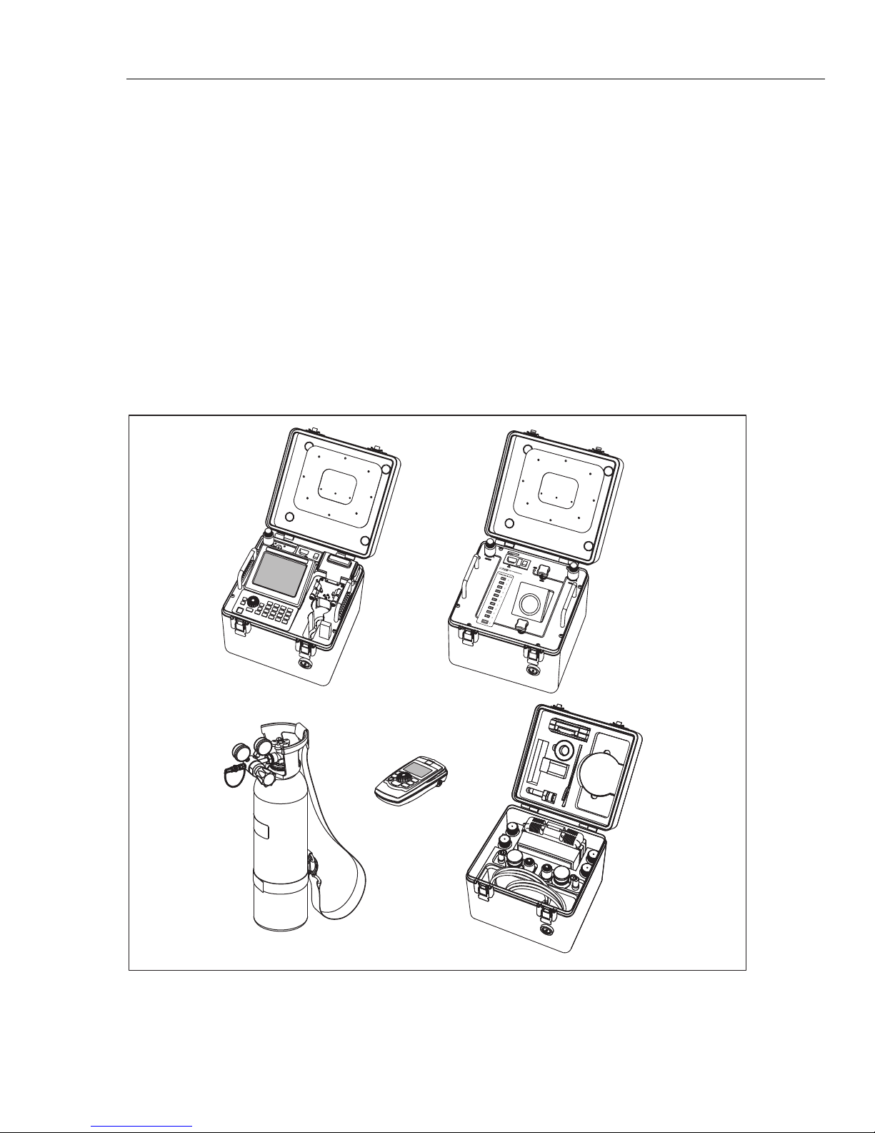
Pressure Controller
“the Controller”
Nitrogen
Cylinder
Handheld
Control
Pressure Intensifier
“the Intensifier”
Accessory
Kit
Figure 1-1. The 4322 Automated Pressure Calibrator
gxj039.eps
1-3
Page 14
4322
Operators Manual
Safety Information
A Warning identifies condition and procedures that are dangerous to the user. A
Caution identifies conditions and procedures that can cause damage to the Product or the
equipment under test.
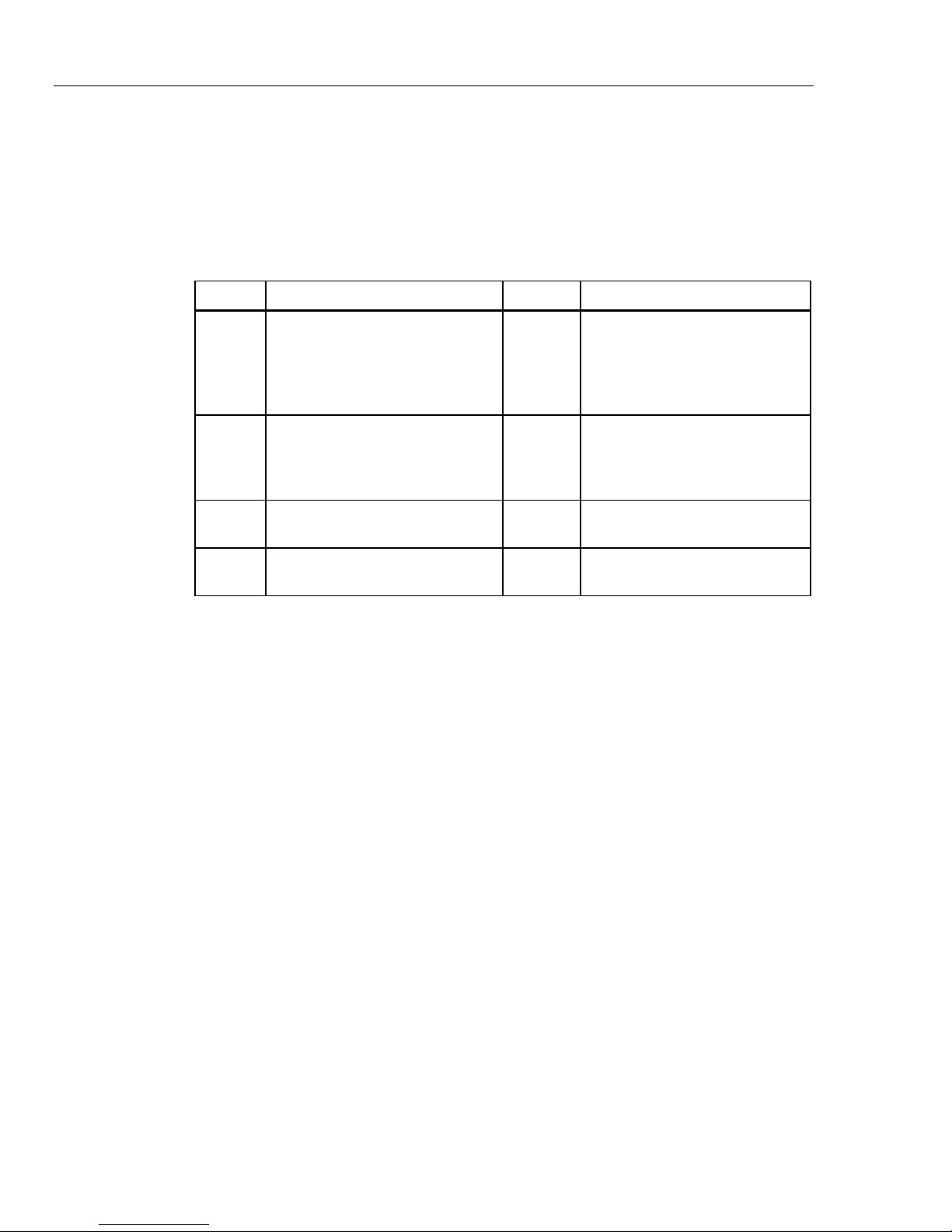
See Table 1-1 for a list of symbols used in this manual and on the Calibrator.
Table 1-1. Symbols
Symbol Description Symbol Description
IEC Measurement Category I –
CAT I
CAT I is for measurements not
directly connected to mains.
Maximum transient Overvoltage is
as specified by terminal markings.
Conforms to European Union
directives
Conforms to relevant North
American Safety Standards.
Do not dispose of this product as
unsorted municipal waste. Go to
Fluke’s website for recycling
information.
Earth ground
Risk of Danger. Important
information. See manual.
Hazardous voltage
Conforms to relevant Australian
EMC requirements
Warning
To prevent possible electrical shock, fire, or personal injury:
• High pressure liquids and gases are potentially hazardous.
Energy stored in these liquids and gases can be released
unexpectedly and with extreme force. High pressure
systems should be assembled and operated only by
personnel who have been instructed in proper safety
practices.
• Read all safety Information before you use the Product.
• Carefully read all instructions.
• Use the Product only as specified, or the protection
supplied by the Product can be compromised.
• Examine the case before you use the Product. Look for
cracks or missing plastic. Carefully look at the insulation
around the terminals.
• Do not use the Product if it operates incorrectly.
• Do not use and disable the Product if it is damaged.
• Use only the mains power cord and connector approved for
the voltage and plug configuration in your country and rated
for the Product.
• Replace the mains power cord if the insulation is damaged
or if the insulation shows signs of wear.
1-4
Page 15

Product Overview and Specifications
The Product Manual Set 1
• Make sure the ground conductor in the mains power cord is
connected to a protective earth ground. Disruption of the
protective earth could put voltage on the chassis that could
cause death.
• Before using this equipment to generate or apply pressure,
ensure integrity of all components to be pressurized and
that they are rated to adequate working pressure.
• Do not put the Product where access to the mains power
cord is blocked.
• Do not use test leads if they are damaged. Examine the test
leads for damaged insulation and measure a known voltage.
• Do not exceed the Measurement Category (CAT) rating of
the lowest rated individual component of a Product, probe,
or accessory.
• Keep fingers behind the finger guards on the probes.
• Do not apply more than the rated voltage, between the
terminals or between each terminal and earth ground.
• Do not touch voltages > 30 V ac rms, 42 V ac peak, or
60 V dc.
• Do not use the Product around explosive gas, vapor, or in
damp or wet environments.
The Product Manual Set
The Calibrator includes an Operators Manual and a Service Manual. Both manuals are
online at
www.flukecal.com and on a CD in the Accessory Kit.
• This 4322 Operators Manual contains basic system and feature information,
operation instructions, and basic user maintenance and troubleshooting information.
• The 4322 Service Manual contains service, calibration, and repair information and
instructions.
Contact Fluke Calibration
To contact Fluke, call one of the following telephone numbers:
• Technical Support USA: 1-877-355-3225
• Calibration/Repair USA: 1-877-355-3225
• Canada: 1-800-36-FLUKE (1-800-363-5853)
• Europe: +31-40-2675-200
• Japan: +81-3-6714-3114
• Singapore: +65-6799-5566
• China: +86-400-810-3435
• Brazil: +55-11-3759-7600
• Anywhere in the world: +1-425-446-6110
To see product information and download the latest manual supplements, visit Fluke
Calibration’s website at
To register your product, visit http://flukecal.com/register-product.
www.flukecal.com.
1-5
Page 16
4322
Operators Manual
Calibration and Repair Information
To schedule and send the Calibrator to Fluke for calibration or repair:
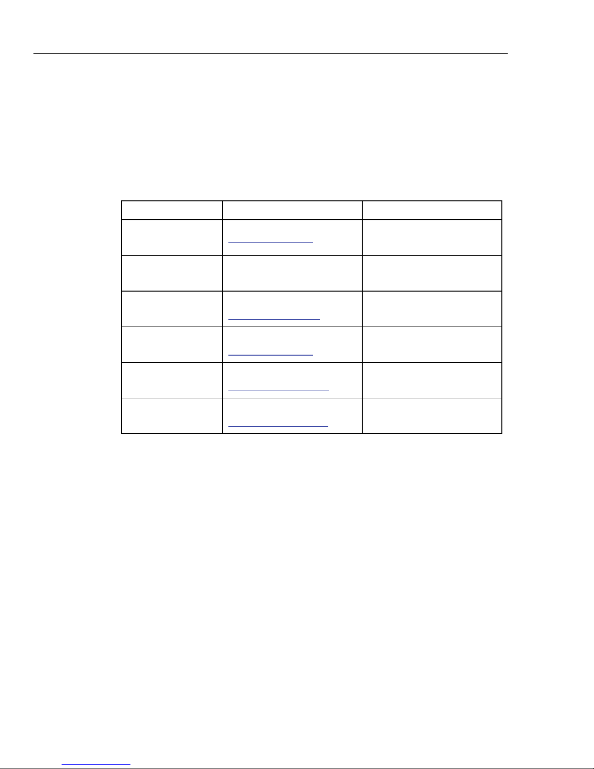
1. Contact the Fluke Calibration Service Center in your area to schedule the calibration
or repair (see Table 1-2).
2. Pack and secure the Calibrator in a shipment box with a minimum of 2 inches of
packing around the Calibrator to prevent damage.
3. Send the Calibrator to the Service Center.
Table 1-2. Fluke Calibration Service Centers
Company Telephone, Fax, and E-mail Support Region
Fluke Calibration US
and worldwide
Customer Service
Tel: 1-877-355-3225
North America and worldwide
Minerva Meettechniek
BV
europascal GmbH
Ohte Giken Inc.
Technology Center
Fluke South East Asia
PTE LTD
Fluke Int'l Corporation
Unpacking
The Calibrator comes in three shipment boxes. The Nitrogen Cylinder comes uncharged
and must be assembled and charged with dry-nitrogen. See Chapter 6 for instructions.
Tel: +31/33.46.22.000
+49 61 81 42 309 0
81/29.840.9111
(65) 6799-5588
+86-10-400-810-3435, Ext 2
Europe, Middle East, and Africa
Germany, Austria, and
Switzerland
Japan
Southeast Asia
China
1-6
Page 17
Product Overview and Specifications
Controller Indicators and Controls 1
Controller Indicators and Controls
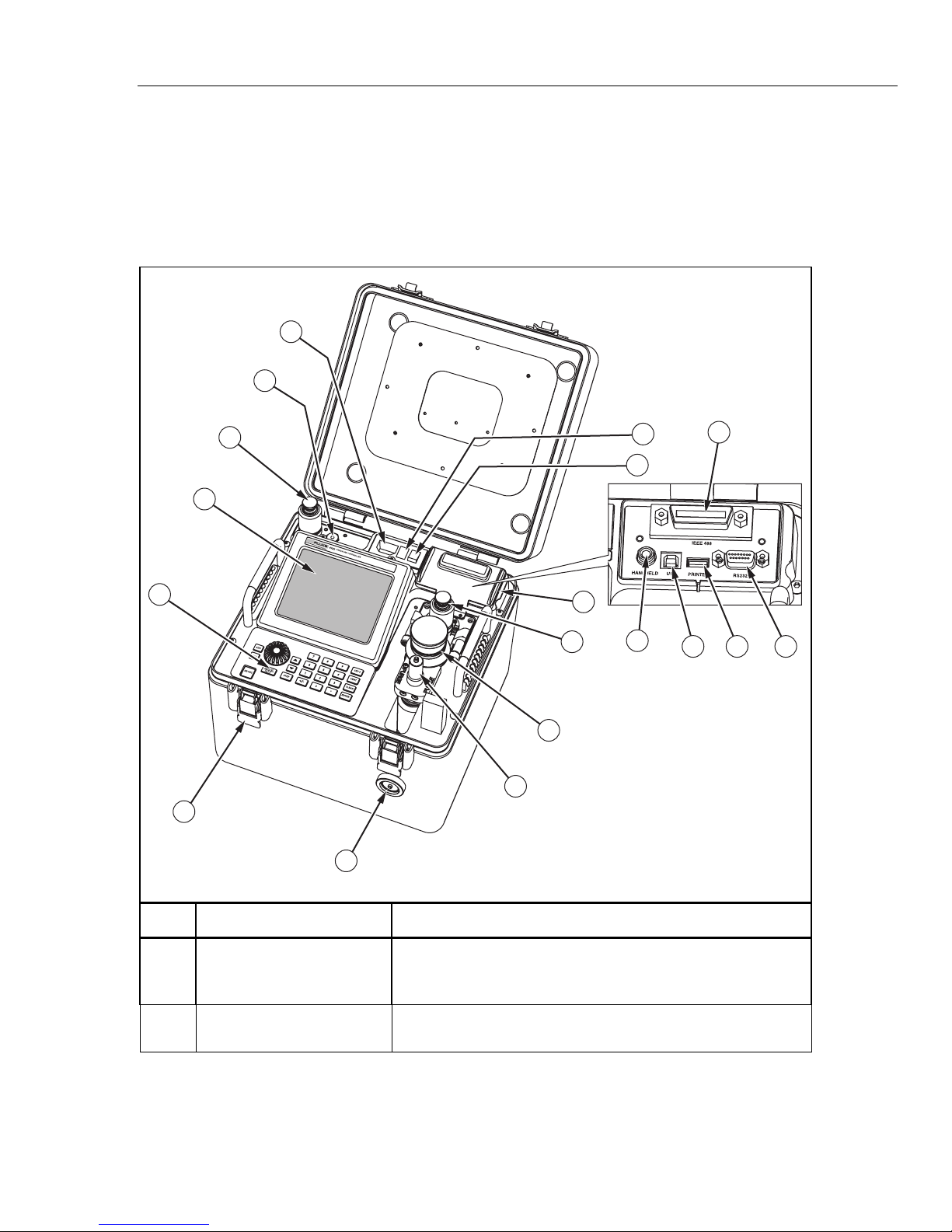
The Pressure Controller (the Controller) shown in Table 1-3, is an electronic pressure
controller that precisely sets, controls, and measures pressure.
Table 1-3 shows the items on the front panel along with a brief description.
Table 1-3. Controller Indicators and Controls
7
6
5
4
3
13
2
1
10
11
12
8
9
14
17
16 1815
gxj024.eps
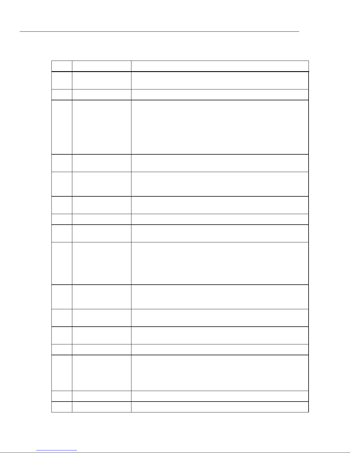
Item Name Function
Case Pressure Equalization
Valve
Spring-Loaded Case
Latches
Push to equalize the pressure inside the case to the pressure
outside of the case. If the pressure is not equal, the case is
difficult to open because it is sealed.
Spring-loaded latches to keep the lid closed and sealed.
1-7
Page 18
4322
Operators Manual
Item Name Function
Table 1-3. Controller Indicators and Controls (cont.)
Control Panel
Display 5-inch color LCD screen.
SUPPLY Port
Control panel with 23 keys and a dual-purpose, push button/rotary dial to
navigate and control the user interface. See Table 1-4.
Female quick connect (QC) supply port that connects to the accessory
Nitrogen Cylinder, Pressure Intensifier, or external nitrogen pressure supply.
Maximum allowable supply pressure is 10,000 psig.
Caution
To prevent injury, the supply must be shut-off and
depressurized to remove the male supply line connector
from the supply port.
ATM (Atmosphere
Vent)
Input Power Cord
Connector
Fuse
Power Switch Electrical power switch to turn on and turn off the unit.
Communications
Module
Vent used by the barometer to measure atmospheric pressure.
Input connector for the supplied power cord. The power entry module and
power cord are a standard appliance inlet, IEC/EN 60320-1/C14, with a
vertical three-prong arrangement.
Electrical fuse that protects the system from overcurrent. For fuse
replacement instructions, see Chapter 6.
Contains all external communication interfaces. See items , , , ,
and .
Female quick connect (QC) test port that connects to the UUT.
Caution
TEST Port
To prevent injury, the supply must be shut-off and
depressurized to remove the female UUT line connector
from the supply port.
Contamination
Prevention System
(CPS)
HOSE PURGE Port
Handheld Control Port
USB USB 2.0 remote operation interface. See Chapter 5, “Remote Operation”.
Printer
Removable and serviceable component that protects the Controller from
contaminates in the UUT. See “About UUT Cross-Contamination
Prevention” in Chapter 2.
Male quick connect (QC) inlet port to purge a hose. See “Hose Purge” in
Chapter 3.
Handheld Control interface. See “Handheld Control Indicators and Controls”
on page 1-11.
USB 2.0 USB printer interface used to print test calibration reports (see
“Print a Test Report” in Chapter 3.
The printer must be PCL-5 compatible.
GPIB IEEE-488.2 remote operation interface. See Chapter 5, “Remote Operation”.
RS-232 Port Used by Fluke Calibration for diagnostic testing.
Note
1-8
Page 19
Product Overview and Specifications
Controller Indicators and Controls 1
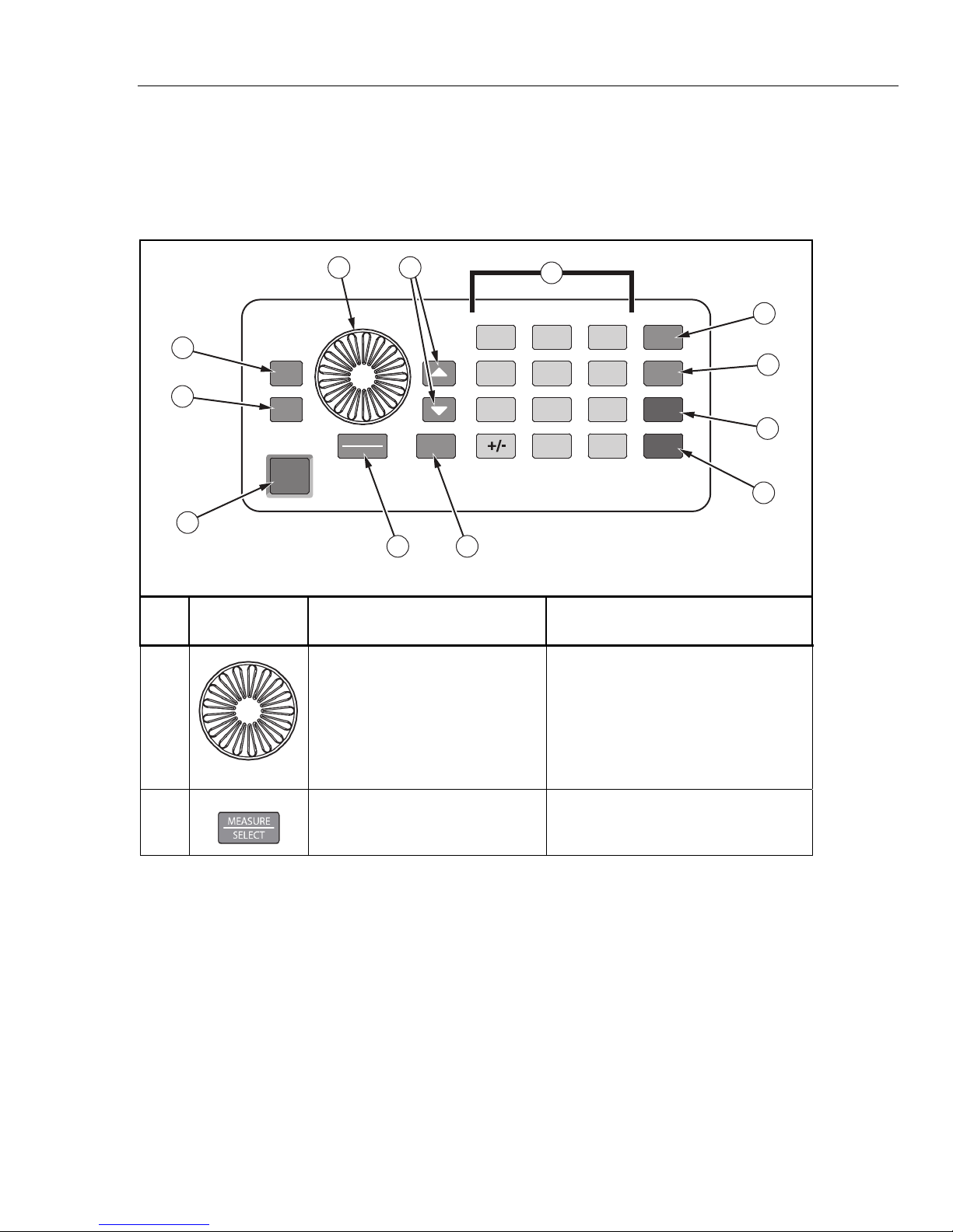
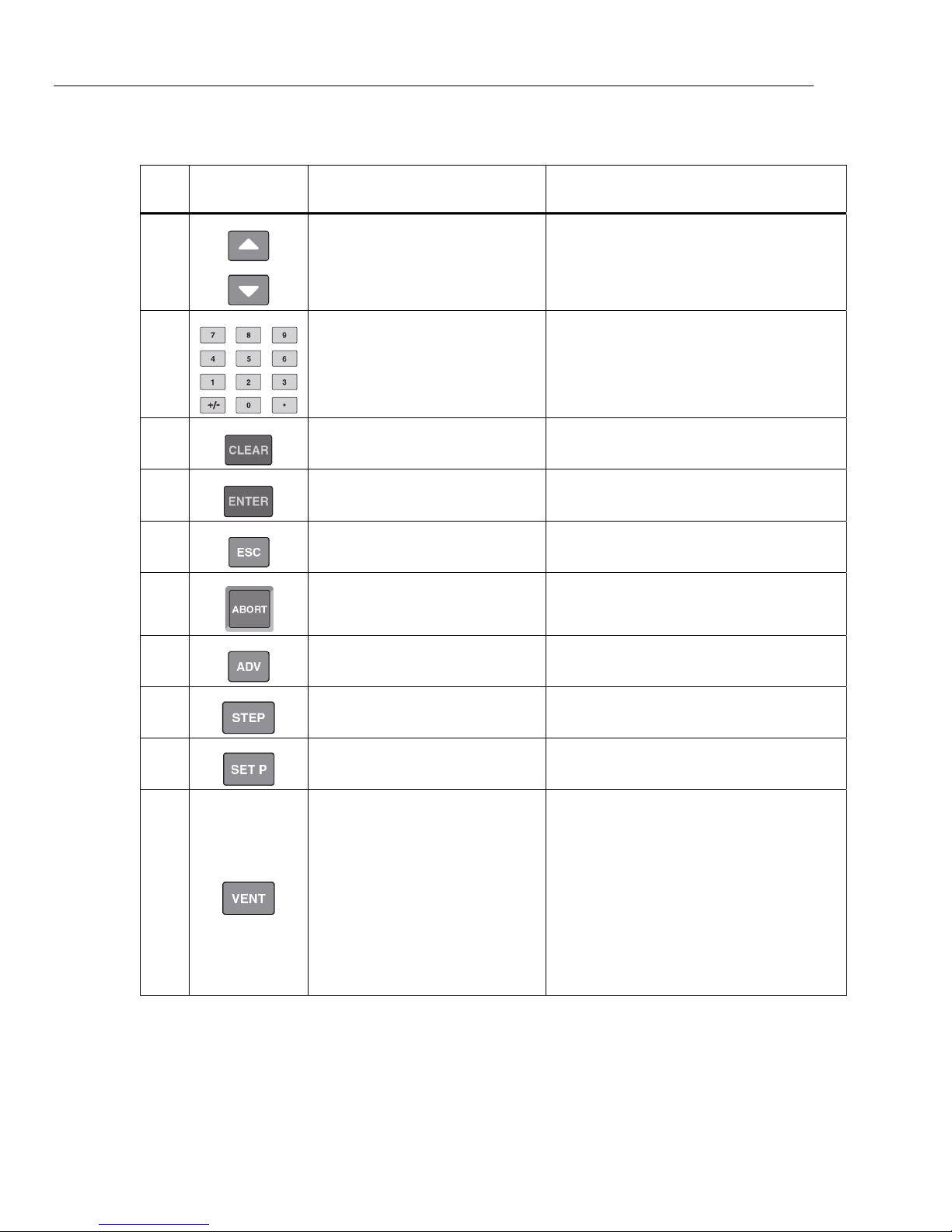
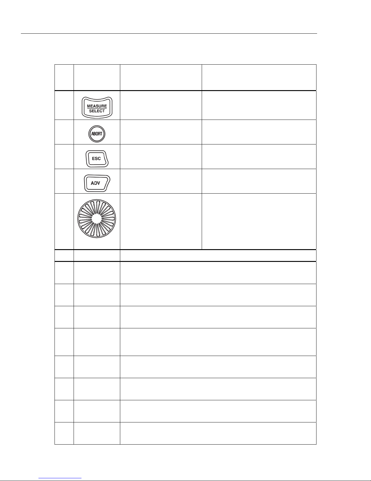
The control panel has 23 keys and a dual-purpose, push button/rotary dial to navigate and
control the user interface. After a test is started, the keys are used to control and adjust
the parameters of the test in progress. Table 1-4 shows the keys on the control panel
along with an explanation of the key functions.
Table 1-4. Control-Panel Keys and Functions
9
ADV
10
8
ESC
ABORT
Item Key
1
MEASURE
SELECT
3
7
4
1
STEP
2
7
Key Function: Menu Navigation
and Test Configuration
Turn to cycle through the
on-screen fields.
Push to open the selected menu or
set the selected value in the
highlighted field.
4
11
8 9
56
2
0
SET P
VENT
CLEAR
3
.
ENTER
12
5
6
gxj012.eps
Key Function: Test in Progress
Turn to increase or decrease the
applied pressure. The faster the dial is
turned, the faster the pressure changes.
Push to set the numerical entry value in
the highlighted field.
Opens the selected menu or sets
the selected value in the
highlighted field.
Sets the numerical entry value in the
highlighted field.
1-9
Page 20
4322
Operators Manual
Table 1-4. Control-Panel Keys and Functions (cont.)
Item Key
Key Function: Menu Navigation
and Test Configuration
Cycles through the on-screen
fields.
Enter numerical values. Enter numerical values.
Clears the numerical value from
the highlighted field.
Sets the numerical entry value in
the highlighted field.
Cancels the current action and
closes the active menu.
No functionality.
No functionality.
Changes the Jog Step between
Coarse and Fine.
Opens the target pressure
configuration menu.
No functionality.
Key Function: Test in Progress
Increases or decreases applied pressure.
The longer a key is pushed, the faster the
pressure increases or decreases.
Clears the numerical value from the
highlighted field.
Sets the numerical entry value in the
highlighted field.
Stops pressure control and pauses the test.
To continue the test, push ESC again.
Aborts (stops) the test and quickly vents the
applied pressure to atmosphere.
Advance to the subsequent test step or
pressure point.
Changes the Jog Step between Coarse and
Fine.
No functionality.
Stops the test and displays a confirmation
prompt to vent.
If “Confirm” is selected, the Controller vents
the applied pressure to atmosphere. If the
user selects “Cancel” on the prompt, the
Controller closes the prompt and the test
resumes.
If a target pressure is set and the Vent key is
pushed, the Controller immediately vents
pressure to atmosphere without a prompt.
1-10
Page 21
Product Overview and Specifications
Handheld Control Indicators and Controls 1
Handheld Control Indicators and Controls
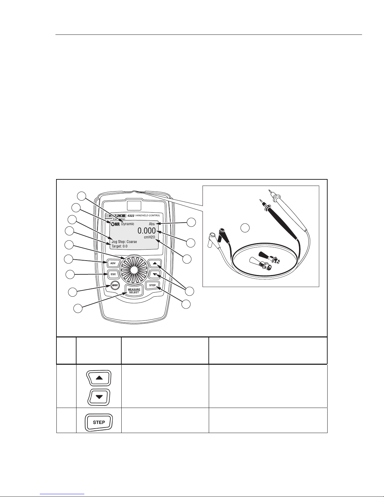
The Handheld Control (the Handheld) has seven keys and a dual-purpose, push
button/rotary dial to navigate and control the user interface (see Table 1-5). The
Handheld has a display that shows information such as test settings and pressure settings.
The keys on the Handheld allow for direct test control of the test in progress. When the
Handheld is connected to the Controller, all of the keys on the Controller are disabled
with the exception of the Abort key. Table 1-5 shows the keys on the Handheld along
with an explanation of their functions.
Note
The Handheld is an independent test control device that controls basic test
functions to complete a test. When the Handheld is in use, the user interface
on the Controller is disabled and blocked by a dialog box. Disconnect the
Handheld when the test is finished to resume normal Controller operation.
Table 1-5. Handheld Control Keys and Functions
11
10
9
8
7
6
5
4
3
Item Key
12
13
14
1
2
Key Function: Menu
Navigation and Test
Configuration
Cycles through the on-screen
fields or increases or decreases
the numerical value in the
highlighted field.
15
gxj033.eps
Key Function: Test in Progress
Push to increase or decrease applied
pressure. The longer a key is pushed, the
faster the pressure will increase or
decrease.
Changes the Jog Step between
Coarse and Fine.
Changes the Jog Step between Coarse and
Fine.
1-11
Page 22
4322
Operators Manual
Item Key
Table 1-5. Handheld Control Keys and Functions (cont.)
Key Function: Menu
Navigation and Test
Configuration
Key Function: Test in Progress
Item Display Item Description
Target Pressure Shows the current target pressure value.
Select
No functionality.
Cancels the current action and
closes the active menu.
No functionality.
Turn to cycle through the
on-screen fields.
Push to open the selected
menu or set the selected value
in the highlighted field.
Opens the selected menu or set the
selected value in the highlighted field.
Aborts (stops) the test and quickly vents the
applied pressure to atmosphere.
Stops pressure control and pauses the test.
To continue the test, push ESC again.
Advance to the subsequent test step or
pressure point.
Turn to increase or decrease the applied
pressure. The faster the dial is turned, the
faster the pressure changes.
Push to set the numerical entry value in the
highlighted field.
1-12
Jog Step
Measurement
Indicator
Pressure Control
Mode
Measurement
Mode
Measured
Pressure
Unit of Measure Shows the unit of measure.
Continuity Leads
and Jacks
Shows the Jog Step setting. The two Jog Step settings are Coarse and Fine.
Refer to “Jog Step Pressure Up or Down” in Chapter 3.
Shows the measurement indicator. See “Measurement Indicators” in Chapter 3.
Shows the active control mode. The indications are Dynamic and Static.
When pressure control is active, the indictors are animated. See “Pressure
Control Modes” in Chapter 3.
Shows the active measurement mode. See “Measurement Modes” in
Chapter 3.
Shows the current applied pressure to the UUT.
Positive (red) and negative (black) leads and jacks to connect the accessory
continuity leads.
Page 23
Product Overview and Specifications
gxj
Pressure Intensifier Indicators and Controls 1
Pressure Intensifier Indicators and Controls
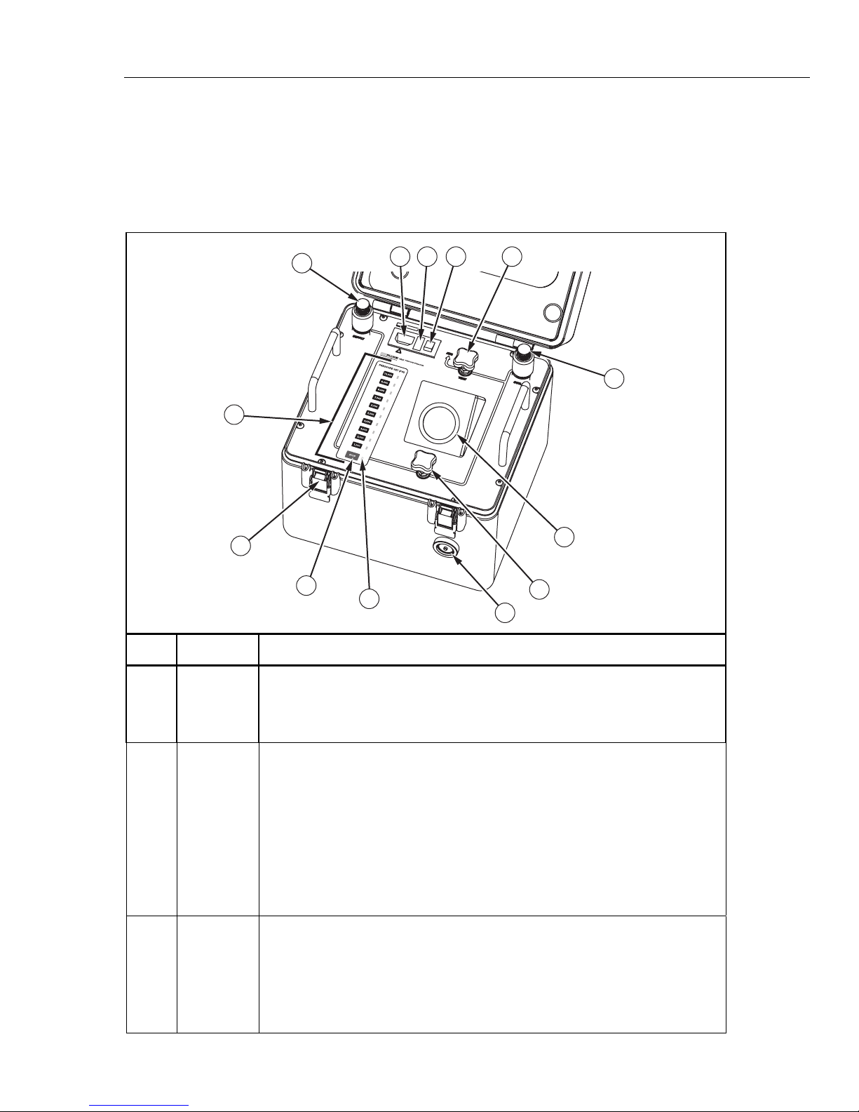
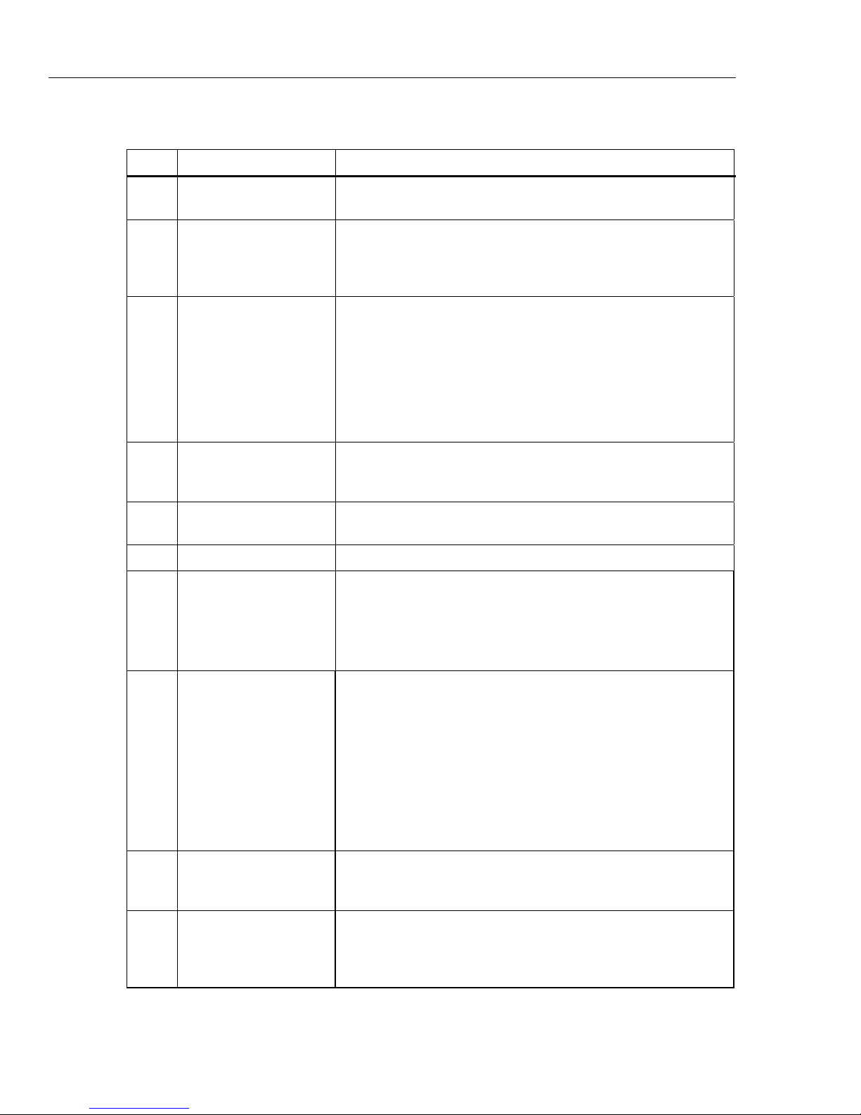
The Pressure Intensifier (the Intensifier) shown in Table 1-6 is an electric pressure
booster system that can boost gas pressure supply from (500 to 3,000) psig up to
10,000 psig. Table 1-6 shows the items on the front panel along with a brief description.
Table 1-6. Intensifier Controls and Indicators
6
5
4
3
7 8 9 10
2
13
1
Item Name Function
12
11
032.eps
Push to equalize the pressure inside the case to the pressure outside of the case.
If the pressure is not equal, the case is difficult to open because it is sealed.
Case
Pressure
Equalization
Valve
Shows the selected target pressure and also shows error conditions and
problems with the system.
When the system is on and no pressure is selected, the STOP key LED is
illuminated (the system is on and ready). The STOP key LED extinguishes when
Status LEDs
a target pressure is selected.
When a target pressure is selected, the status LED to the right of the key
illuminates. The LED stays illuminated until is pushed or an error occurs.
System error conditions are shown by flashing LEDs. See Chapter 6 for
troubleshooting information.
Single push button that stops the production of boost pressure and cancels the
pressure selection. Use the Vent Valve to release boost pressure at a higher
rate.
Caution
To prevent Controller contamination, do not open the Intensifier
Vent Valve while the Controller is actively controlling pressure.
1-13
Page 24
4322
Operators Manual
Item Name Function
Table 1-6. Intensifier Controls and Indicators (cont.)
Spring-Loaded Case
Latches
Intensifier Pressure
Selection Keys
(PRESSURE SET PSI)
SUPPLY Port
Spring-loaded latches used to keep the lid closed and sealed.
Keypad used to select the Intensifier pressure. Keypad selections
are in 1,000 psig increments that range from 1,000 psig to 10,000
psig. Each key is has a status LED indicator that visually shows the
selected boost pressure and system status (see ).
Female quick connect (QC) supply port that connects to the
accessory Nitrogen Cylinder or external nitrogen pressure supply.
Supply must be between (500 to 3,000) psig.
Caution
To prevent injury, the supply must be shut off
and depressurized to remove the male supply
line connector from the supply port.
Input Power Cord
Connector
Fuse
Power Switch Electrical power switch to turn on and turn off the unit.
Vent Valve
(VENT)
Input connector for the supplied power cord. The power entry module
and power cord are a standard appliance inlet (IEC/EN 60320-1/C14)
with a vertical three-prong arrangement.
Electrical fuse that protects the system from overcurrent. For fuse
replacement instructions, refer to “Fuse Replacement” in Chapter 6.
Needle valve to manually discharge system pressure to
atmosphere.
Note
Source pressure can be depleted very quickly if it is not turned
off before venting the system.
1-14
OUTLET Port
Intensifier Pressure
Gauge (INTENSIFIER
PRESSURE)
Isolation Valve
(ISOLATION)
Female quick connect (QC) outlet port that connects the Controller.
Caution
To prevent injury, the Intensifier must be shut
off and depressurized to remove the male
supply line connector from the outlet port. For
quick disconnects with the system on, isolate
the pressure with the isolation valve and open
the vent valve to remove pressure on the
connector.
Visual Indication of the Intensifier pressure in psig.
Needle valve that shuts-off the pressure supply to the OUTLET
Port. Pressure isolation is used for pressure accumulation
troubleshooting procedures. It is also used to relieve pressure on
the OUTLET port to disconnect the hose.
Page 25
Product Overview and Specifications
Accessory Kit Items 1
Accessory Kit Items
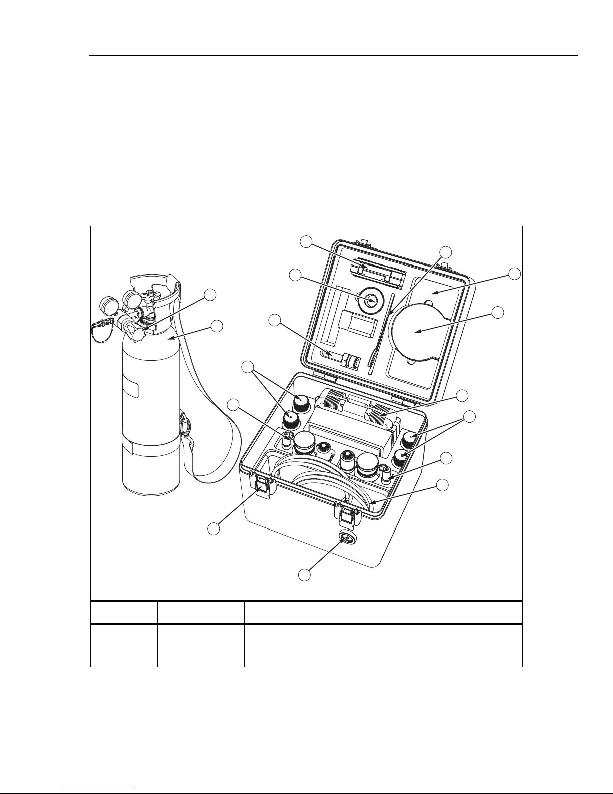
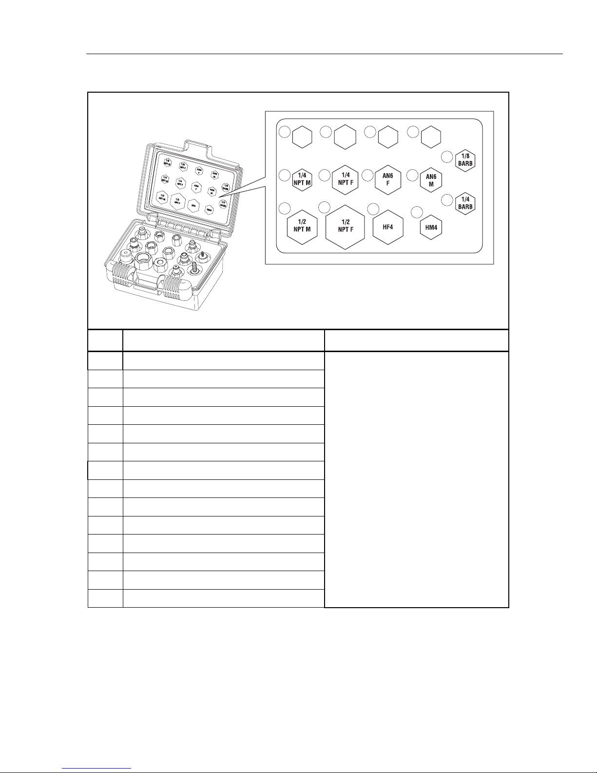
The Calibrator includes the accessories listed Table 1-7, Table 1-8, and Table 1-9.
Table 1-7 shows the accessories found in the Accessory Kit, Table 1-8 is a list of adapters
in the Adaptors Kit, and Table 1-9 is a list of additional seals, filters, and fuses in the
Spares Kit.
To order replacement parts or additional accessories, contact Fluke Calibration and
reference the part numbers listed in the “List of Replacement Parts” section in the 4322
Service Manual.
Table 1-7. Accessories
10
11
9
14
15
4
2
8
6
7
6
5
3
12
13
Item Name Function
Case Pressure
Equalization Valve
1
gxj034.eps
Push to equalize the pressure inside the case to the pressure
outside of the case. If the pressure is not equal, the case is difficult
to open because it is sealed.
1-15
Page 26
4322
Operators Manual
Item Description Function
Table 1-7. Accessories (cont.)
Spring-Loaded Case
Latches
Hoses
CPS (orange)
CPS (blue)
CPS Waste Containers Waste container (60 ml) with lid used with the CPS.
Adapters Kit QC adapters for the UUT. See Table 1-8.
Nitrogen Cylinder Fill
Adapter
PTFE Tape Tape to use on NPT fittings.
Spares Kit
Regulator Wrench
DMM Holder Foam cutout for a Fluke Digital Multimeter.
Spring-loaded latches that keeps the lid closed and sealed.
System hoses. The Calibrator comes with:
• One Nitrogen Cylinder connection hose (6 ft)
• One system interconnect hose (6 ft)
• One blue UUT test hose (10 ft)
• One orange UUT test hose (10 ft)
Orange and blue Contamination Prevention System (CPS). See
“UUT Cross-Contamination Prevention” in Chapter 2.
Adapter used to connect a fill system to the Nitrogen Cylinder.
Contains seals, fuses, and additional replacement parts. See
Table 1-9.
Wrench for installation of the Nitrogen Fill Cylinder Adapter and
Regulator.
Manuals CD
Nitrogen Cylinder
Regulator
Nitrogen Cylinder
CD that contains the 4322 Operators Manual and 4322 Service
Manual.
Pressure regulator that lets you turn on and turn off pressure and
also see the amount of pressure in the Nitrogen Cylinder.
2,000 psig Nitrogen Cylinder. Maximum cylinder pressure is
2,000 psig.
Warning
To prevent injury, do not over pressurize the
Nitrogen Cylinder. Maximum pressure of the
Cylinder is 2,000 psig.
1-16
Page 27
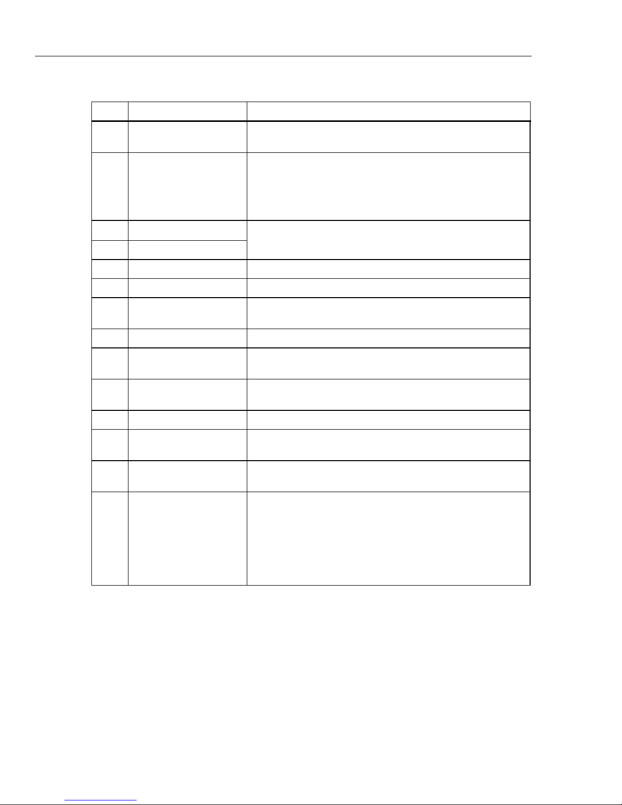
Product Overview and Specifications
gxj
Accessory Kit Items 1
Table 1-8. Accessories - Adaptor Kit
6 9 123
1/8
NPT M
1/8
NPT F
AN4
F
AN4
M
14
2
1
5 8 11
4
7
13
10
035.eps
Item Name Function
FITTING, 1/2 MALE PIPE THREAD (NPT) Quick-connect adapter. Each adaptor is
FITTING, 1/4 MALE PIPE THREAD (NPT)
FITTING, 1/8 MALE PIPE THREAD (NPT)
FITTING, 1/2 FEMALE PIPE THREAD(NPT)
marked with its maximum working pressure.
See the Specifications section in this chapter
for maximum working pressures.
FITTING, 1/4 FEMALE PIPE THREAD (NPT)
FITTING, 1/8 FEMALE PIPE THREAD (NPT)
FITTING, HF4 EQUIVALENT
FITTING, AN6 FEMALE
FITTING, AN4 FEMALE
FITTING, HM4 EQUIVALENT
FITTING, AN6 MALE
FITTING, AN4 MALE
FITTING, 1/4 ID HOSE BARB
FITTING, 1/8 ID HOSE BARB
1-17
Page 28

4322
Operators Manual
O-RING,0.05 IN. W X 0.042 IN. ID,VITON,75 DUROMETER,BROWN
O-RING,VITON,1MM W X 14MM ID,90 DURO,BLACK
O-RING,VITON,1MM W X 12MM ID,90 DURO,BLACK
O-RING,VITON,1MM W X 8MM ID,90 DURO,BLACK
O-RING,FLUOROCARBON,SHORE A 75,BLK,AS 568A-014,.489 ID,.070 W,ROHS COMPL.
48547,BUSHING NON-RIBBED
O-RING,CAST URETHANE,90 DURO,003 (0.060 W X 0.056 ID)
O-RING,VITON,2-002,3/64 ID,9/64 OD,3/64 W,DURO 90,BLACK
SEAL ASSEMBLY, HIGH PRESSURE,T61 SEAL /P02 BACKUP RING /FKM O-RING
O-RING,VITON,1MM W X 3.5MM ID,90 DURO,BLACK
4322-5772,DECAL, SPARE PARTS CASE
CASE,ABS,3.875INX2.375INX1.375IN,WITH HANDLE,BLACK
FUSE,5A,250VAC,TIME LAG,5X20MM,CERAMIC
4322-5933,CUT DETAIL, COALESCING FILTERS
FUSE,FUSE,5X20MM,1A,250V,SLOW
4322-5828,WRENCH,INTENSIFIER PISTON
4322-5860,TOOL, PISTON INSERTION, 4322
O-RING,0.05 IN. W X 0.042 IN. ID,VITON,75 DUROMETER,BROWN
Table 1-9. Accessories - Spares Kit (Not Shown)
Description
Specifications
General Specifications
Power Requirements ............................................ 100 V ac to 240 V ac (-15 %, +10 %), 50 Hz to 60 Hz
Maximum Power Consumption
Controller ............................................................ 110 VA
Intensifier ............................................................ 200 VA
Operating Temperature Range ............................ 0 °C to 50 °C
Storage Temperature Range ................................ -30 °C to 71 °C
Humidity ................................................................. 5 % to 95 %
Vibration ................................................................ Meets MIL-T-28800D
Altitude (operation) ............................................... 2,000 m
Weight
Controller ............................................................ ~12 kg (27 lb)
Intensifier ............................................................ ~14 kg (31 lb)
Accessory Kit with Handheld Control .................. ~12 kg (27 lb)
Nitrogen Cylinder ................................................ ~12 kg (26 lb)
Dimensions
Controller, Intensifier, and Accessory Kit ............ 32.5 cm Height x 30.5 cm Width x 30.5 cm Depth
Nitrogen Cylinder ................................................ 68.5 cm Height x 17.8 cm Diameter (27 in Height x 7 in Diameter)
Remote Communication Interfaces..................... RS-232, USB type B, IEEE-488.2, USB type A (PRINTER port only)
Pressure Range ..................................................... 3.5 kPa (0.5 psi) absolute to 70 MPa (10,000 psi)
Operating Medium ................................................ Dry nitrogen supply, or ambient air compressed by on-board pump.
Warm-up Time ....................................................... 15 minutes from power on, after at least 60 minutes ambient
(13 in Height x 12 in Width x 12 in Depth)
temperature acclimation time within the working temperature range.
1-18
Page 29
Product Overview and Specifications
Specifications 1
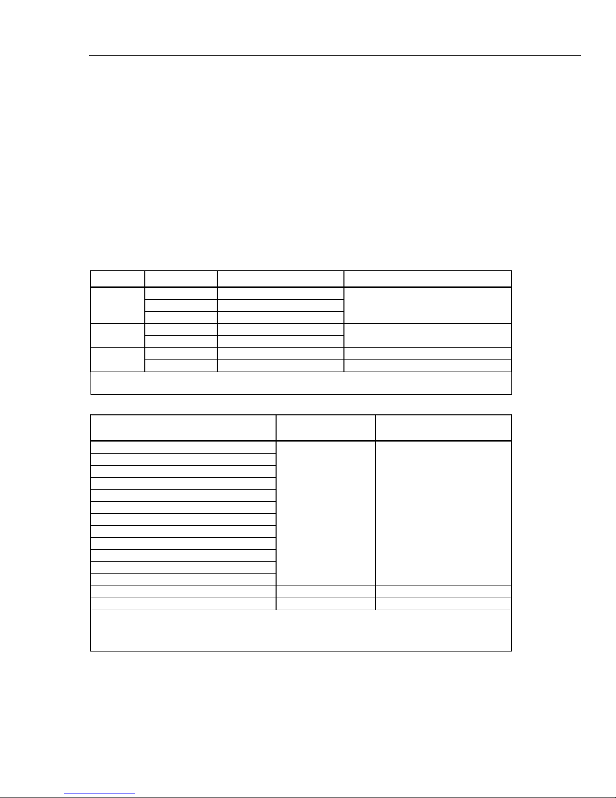
Pressure Limits
Recommended Supply Pressure
Controller ............................................................ Greater of 700 kPa (100 psi) or 10 % above max target pressure, not
Intensifier ............................................................ 3.5 MPa to 14 MPa (500 psi to 2,000 psi)
Max System Working Pressure ........................... 70 MPa (10,000 psi)
Max Supply Pressure
Controller ............................................................ 73 MPa (10,500 psi)
Intensifier ............................................................ 20 MPa (3,000 psi)
Max Nitrogen Cylinder Pressure ......................... 14 MPa (2,000 psi)
Max Regulator Pressure
Inlet ..................................................................... 40 MPa (6,000 psi)
Outlet .................................................................. 17 MPa (2,500 psi)
Connections, Accessories, and Adapters .......... Refer to the subsequent tables.
Controller, Intensifier, and Nitrogen Cylinder Connections
Unit Name
TEST Port IQC70 female, located on CPS
Controller
Hose Purge IQC70 male
Intensifier
Nitrogen
Cylinder
Note:
1. IQC70 is a Fluke Calibration interlocking quick connection nominally rated to 70 MPa (10,000 psi).
SUPPLY Port IQC70 female
OUTLET Port IQC70 female
VALVE CGA580 nipple 40 MPa (6,000 psi)
Regulator Outlet Miniature QC female 20 MPa (3,000 psi)
to exceed 73 MPa (10,500 psi).
Type of Fittings
[1]
Maximum Working Pressure Limit
70 MPa (10,000 psi) SUPPLY Port IQC70 female
70 MPa (10,000 psi)
Accessory Kit Fittings
Name
Fitting, 1/2 Male Pipe Thread (NPT)
Fitting, 1/4 Male Pipe Thread (NPT)
Fitting, 1/8 Male Pipe Thread (NPT)
Fitting, 1/2 Female Pipe Thread (NPT)
Fitting, 1/4 Female Pipe Thread (NPT)
Fitting, 1/8 Female Pipe Thread (NPT)
Fitting, HF4 Equivalent
Fitting, AN6 Female
Fitting, AN4 Female
Fitting, HM4 Equivalent
Fitting, AN6 Male
Fitting, AN4 Male
Fitting, 1/4 ID Hose Barb IQC70 male 700 kPa (100 psi)
Fitting, 1/8 ID Hose Barb IQC70 male 700 kPa (100 psi)
Notes:
1. IQC70 is a Fluke Calibration interlocking quick connection nominally rated to 70 MPa (10,000 psi).
2. Working pressures indicated are for adaptors only. Actual pressure capability may be limited by the integrity or maximum
working pressure of the fitting to which the adaptor is connected.
Type of Fittings
IQC70 male 70 MPa (10,000 psi)
[1]
Maximum Working
Pressure Limit
[2]
1-19
Page 30
4322
Operators Manual
Test hose 3 m (10 ft)
Interconnect hose 1.8 m (6 ft) IQC70 male stem at both ends. 70 MPa (10,000 psi)
Supply hose 1.8 m (6 ft)
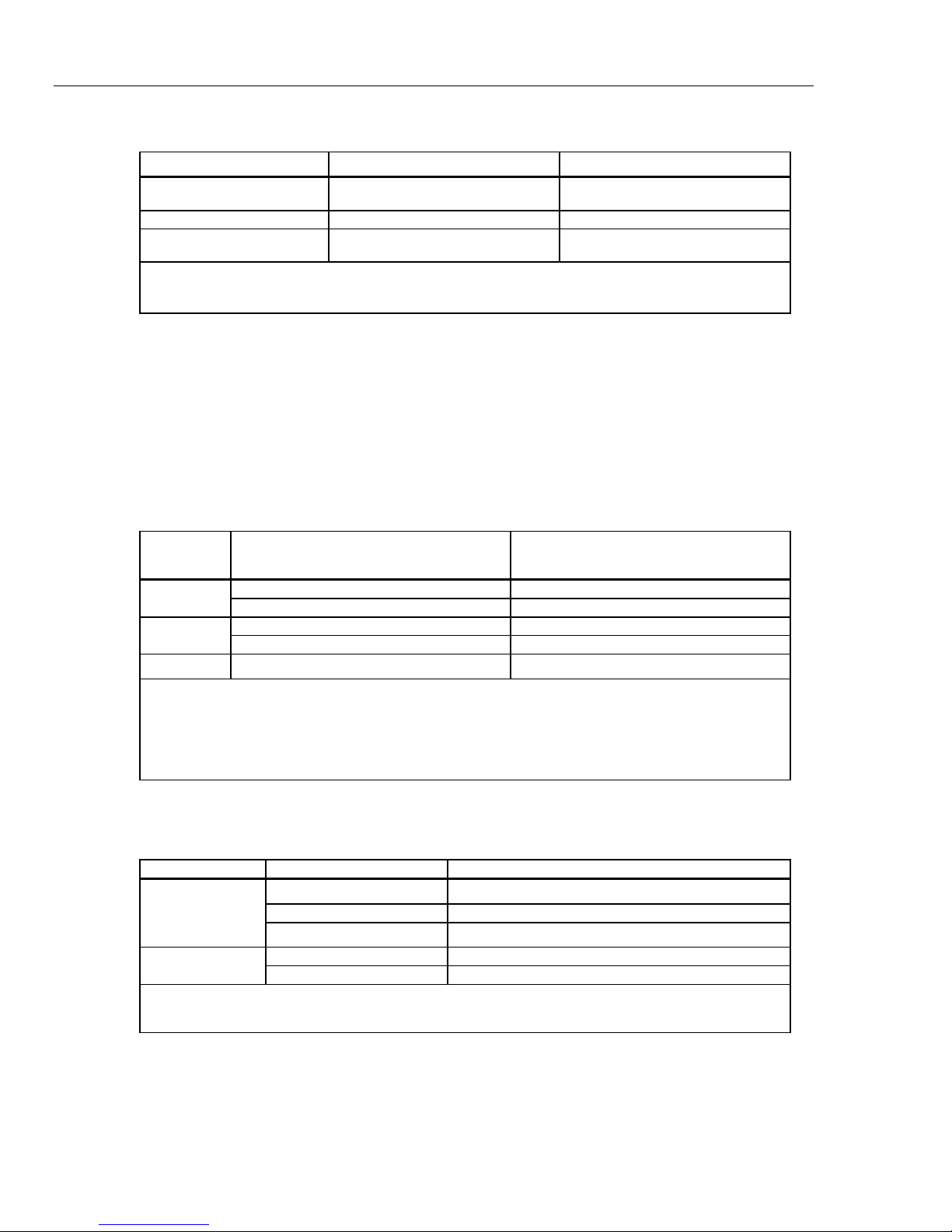
Measurement Specifications
Barometer Module Range .................................... 70 kPa to 110 kPa absolute (10 psi to 16 psi) absolute
Pressure Transducer Module Ranges
Note: Pressure modules are switched automatically and transparently to the operator.
A150k .................................................................. 3.5 kPa to 150 kPa absolute (0.5 psi to 21.5 psi) absolute
G700k ................................................................. 50 kPa to 700 kPa gauge (7 psi to 100 psi) gauge
G10M .................................................................. 700 kPa to 10 MPa gauge (100 psi to 1,500 psi) gauge
G70M .................................................................. 10 MPa to 70 MPa gauge (1,500 psi to 10,000 psi) gauge
Resolution ............................................................. To lesser of 1 ppm of reading or 1 ppm of 4 psi (0.00004 psi or 2.5 Pa)
Test Hoses
Name
Type of Fittings
IQC70 male stem at one end, and
IQC070 female coupling at the other.
IQC70 male stem at one end, and
miniature QC at the other.
Notes:
1. IQC70 is a Fluke Calibration interlocking quick connection nominally rated to 70 MPa (10,000 psi).
2. Hose limited to 3,000 psi due to miniature QC used to connect to the fitting on the regulator.
[1]
Maximum Working Pressure Limit
70 MPa (10,000 psi)
20 MPa (3,000 psi)
[2]
Measurement Uncertainty
Gauge,
Absolute, or
Range
Uncertainty
Vacuum
[2]
Gauge
Absolute
Vacuum
Notes:
1. Measurement uncertainty is defined as the maximum deviation from the indicated value of measured pressure for 1 year
after alignment including hysteresis, linearity, repeatability, stability, temperature, humidity effects, and calibration reference
standard measurement uncertainty. Expression of uncertainty uses a coverage factor of 2 and conforms with the
recommendations of the ISO Guide to the Expression of Uncertainty in Measurement.
2. Negative gauge and vacuum pressure values assume the ambient atmospheric pressure is approximately 101 kPa
(14.7 psi) absolute.
-98 kPa to +28 kPa (-14.2 psi to +4 psi) gauge ±28 Pa (0.004 psi, 0.1 in H
28 kPa to 70 MPa (4 psi to 10,000 psi) gauge ±0.1 % of reading
3.5 kPa to 130 kPa (0.5 psi to 19 psi) absolute ±28 Pa (0.004 psi, 0.1 in H
130 kPa to 70 MPa (19 to 10,000 psi) absolute ±0.1 % of reading
[2]
0 kPa to 98 kPa (0 to 29 inHg) ±28 Pa (0.008 inHg)
[1]
O at 20 °C)
2
O at 20 °C)
2
Pressure Control Specifications
Control Precision .................................................. Greater of ± 28 Pa (0.004 psi) or 0.025 % of reading.
Control Ranges
Pressure Source Gauge, Absolute, or Vacuum Range
[1]
On-board Pump
Gauge
Absolute 3.5 kPa (0.5 psi) to 2 MPa (300 psi) absolute
Vacuum (negative gauge)
External Gas Supply
Note:
1. Negative gauge and vacuum pressure values assume the ambient atmospheric pressure is approximately 101 kPa
(14.7 psi) absolute.
Gauge 28 kPa (4 psi) gauge to 70 MPa (10,000 psi) gauge
Absolute 130 kPa (19 psi) to 70 MPa (10,000 psi) absolute
-98 kPa (-14.2 psi) gauge to 2 MPa (300 psi) gauge
[1]
0 kPa to 98 kPa (29 inHg)
1-20
Page 31
Product Overview and Specifications
Specifications 1
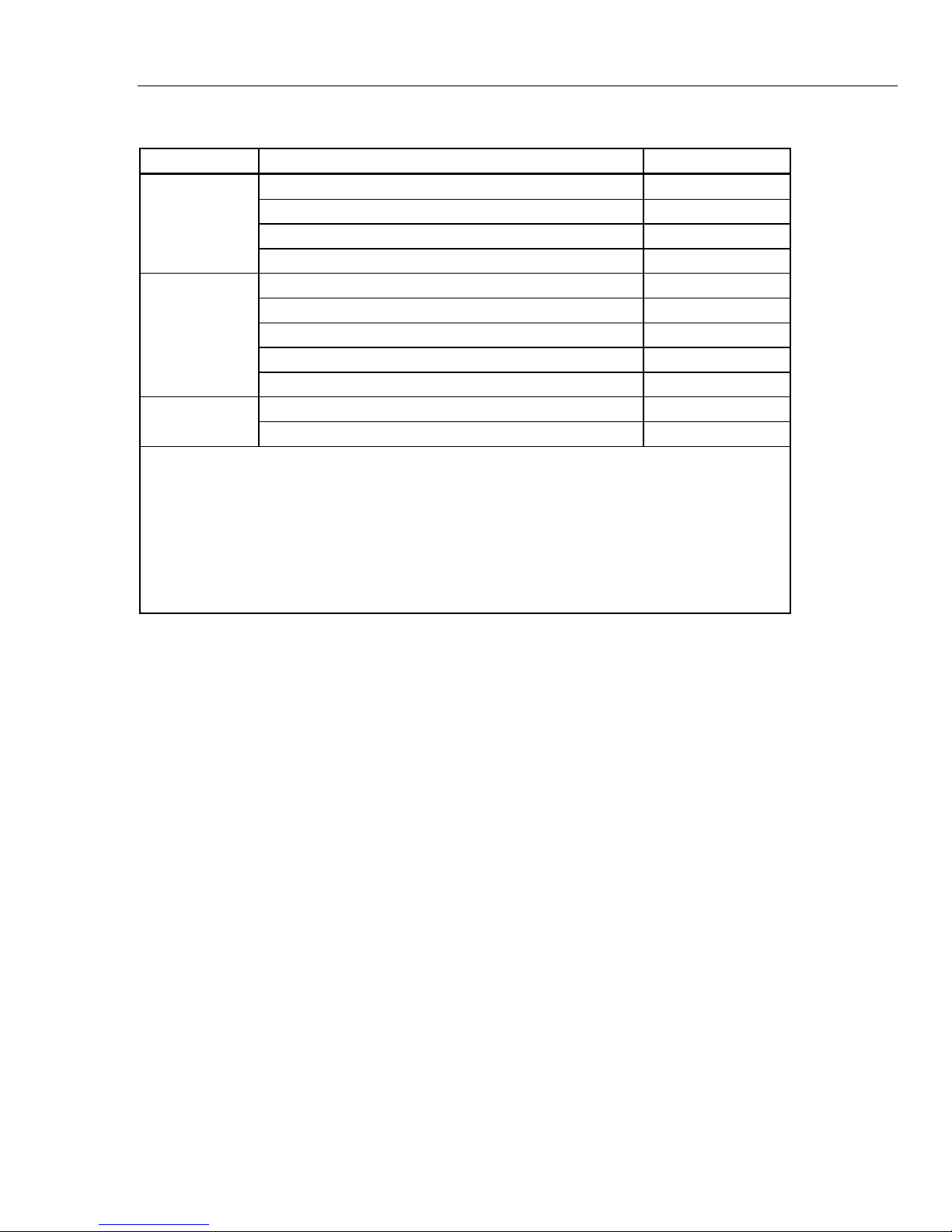
Typical Control Set Times
[1] [6]
[2]
[3]
[4]
[1] [6]
[1] [6]
[2]
[3]
[4]
[1] [6]
[1] [6]
[5]
Measure Mode Range
<28 kPa (4 psi) gauge
Gauge
[7]
28 kPa to 700 kPa (4 to 100 psi) gauge
700 kPa (100 psi) gauge to 7 MPa (1,000 psi) gauge
7 MPa (1,000 psi) gauge to 70 MPa (10,000 psi) gauge
<14 kPa (2 psi) absolute
14 kPa to 130 kPa (2 to 19 psi) absolute
Absolute
130 kPa to 700 kPa (19 to 100 psi) absolute
700 kPa (100 psi) to 7 MPa (1,000 psi) absolute
7 MPa (1,000 psi) to 70 MPa (10,000 psi) absolute
Vacuum
Notes:
1. Assumes 100 cc test volume, uses on-board pump control.
2. Assumes 100 cc test volume with external gas supply.
3. Assumes 50 cc test volume with external gas supply.
4. Assumes 25 cc test volume with external gas supply.
5. Set times assume pressure steps of no greater than 10 % of target pressure and reflect time to ready using default control
6. Times for sub-atmospheric set points assume that the temperature is below the boiling point of any liquid in the UUT and
7. Negative gauge and vacuum pressure values assume the ambient atmospheric pressure is approximately 101 kPa
[7]
limits in dynamic control mode.
CPS for the target pressure.
(14.7 psi) absolute.
>88 kPa (26 inHg) vacuum
0 kPa to 88 kPa (0 inHg to 26 inHg) vacuum
Time (seconds)
90
30
30
60
180
90
30
30
60
180
90
Pressure Switch Testing Specifications (Handheld)
Maximum Input Voltage........................................ 10 V (protected up to 1,000 V dc)
Resistance Thresholds ........................................ Set to 1 KΩ opened / 90 Ω closed (±5 %)
Dead-band Limits .................................................. -98 kPa (-14.2 psi) gauge to 70 MPa (10,000 psi) gauge
1-21
Page 32

4322
Operators Manual
1-22
Page 33

Chapter 2
Setup
Title Page
Introduction ........................................................................................................ 2-3
Quick-Connector Fittings .................................................................................. 2-3
Configure the Pressure Supply ........................................................................... 2-4
Controller Only .............................................................................................. 2-4
Controller and Nitrogen Cylinder .................................................................. 2-5
Controller and Intensifier .............................................................................. 2-5
Internal and External Supply Setting ............................................................. 2-6
Contamination Prevention ................................................................................. 2-8
Install the CPS ............................................................................................... 2-9
Remove the CPS ............................................................................................ 2-10
Connect the Handheld Control Accessory ......................................................... 2-10
Connect to a Unit Under Test (UUT) ................................................................ 2-11
Make a Head-Height Correction ........................................................................ 2-14
Controller Settings ............................................................................................. 2-15
The Settings Menu ......................................................................................... 2-15
Security Levels .............................................................................................. 2-20
Sounds and Alarm Volume............................................................................ 2-21
2-1
Page 34

4322
Operators Manual
2-2
Page 35
Setup
Introduction 2
Introduction
This chapter supplies information and instructions on how to configure the Calibrator for
operation.
Quick-Connector Fittings
To quickly connect and disconnect hoses, both the Controller and the Intensifier are
equipped with Fluke IQC070 interlocking quick-connects (QC) with nominal maximum
working pressure (MWP) of 70 MPa (10,000 psi). Maximum working pressures of the
adapter fittings supplied in the Adapters Kit are listed in the Specifications section in
Chapter 1.
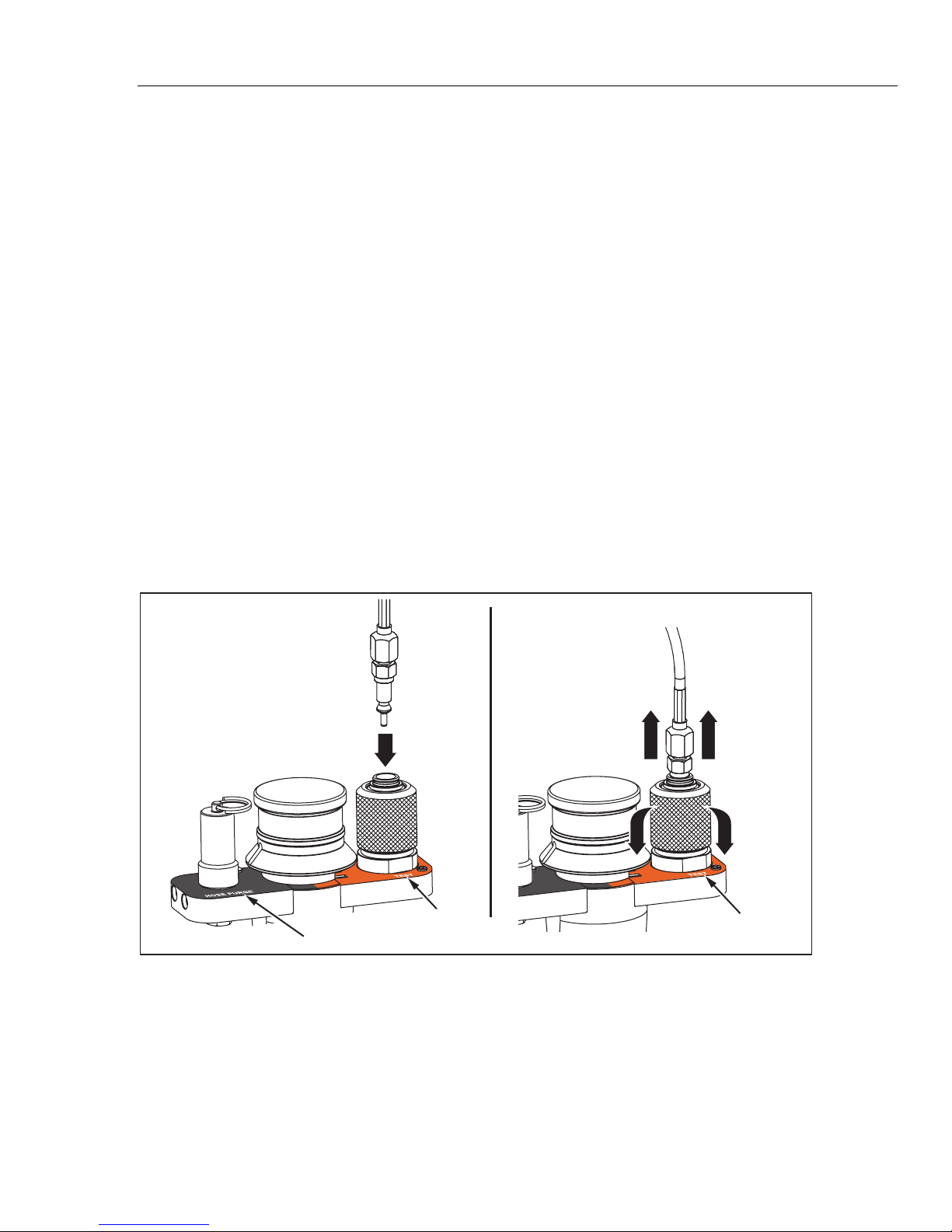
To connect a hose to a QC, push the male connector on the hose into the female
connector on the unit. To release the connector, remove pressure from the connector and
push down on the collar (see Figure 2-1). The Accessory Kit includes a variety of QC
adapters and fittings to attach to a UUT.
Warning
To prevent injury and damage to the system, do not try to
disconnect or connect a hose when pressure is on the QC
connectors. The QC is locked when pressure is applied.
Each QC fitting contains a small, in-line filter to prevent system contamination. The
filters are replaceable and can be replaced by qualified service personnel, see the 4322
Service Manual for instructions on how to replace the filters.
Connect Disconnect
Hose
(Male)
Hose
(Male)
Connector
(Female)
Connector
(Female)
Test Port
Hose Purge
Figure 2-1. Quick-Connector Operation Example
Test Port
gxj003.eps
2-3
Page 36
4322
Operators Manual
Configure the Pressure Supply
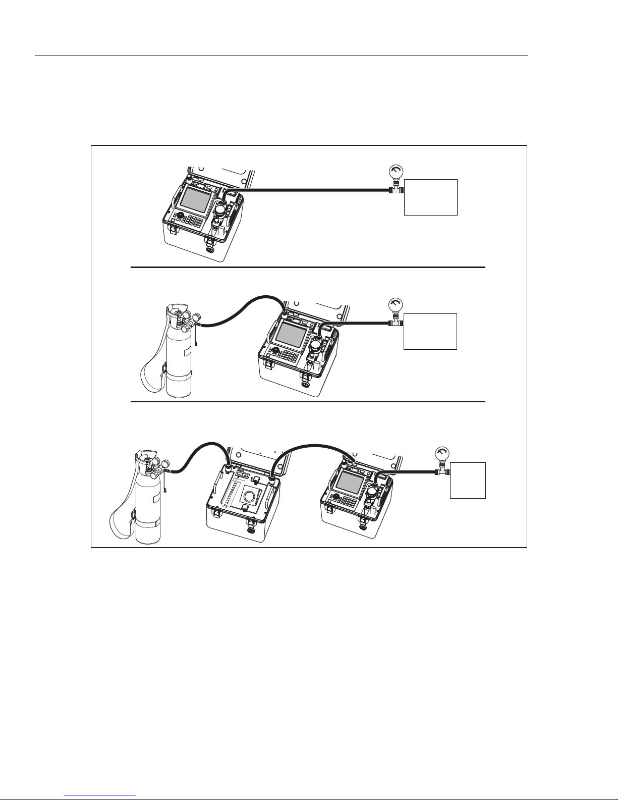
The Calibrator has three configurations to maximize portability as shown in Figure 2-2.
Read the subsequent sections from more information on each configuration along with
instructions on how to set up the Calibrator for the configuration.
Controller Only Configuration
(-14.2 psig to 305 psig)
UUT
Controller
Nitrogen
Cylinder
Nitrogen
Cylinder
Controller and Nitrogen Cylinder Configuration
Controller and Intensifier Configuration
Figure 2-2. Pressure Supply Configurations
(-14.2 psig to 2,000 psig)
(-14.2 psig to 10,000 psig)
Intensifier
UUT
Controller
Controller
UUT
gvw003.eps
Controller Only
The Controller only configuration provides maximum portability when the pressure
necessary to calibrate the UUT is between -14.2 psig and 305 psig. In this configuration,
the Controller is directly connected to the UUT without an external supply. The
Controller has an internal electric pump that can generate and supply up to 305 psig of
compressed air without an external source of pressure. If more than 305 psig is necessary
for the calibration, connect the Controller to an external supply such as the Nitrogen
Cylinder or Intensifier.
2-4
Page 37

Setup
Configure the Pressure Supply 2
Controller and Nitrogen Cylinder
The Controller and Nitrogen Cylinder configuration provides maximum portability when
the pressure necessary to calibrate the UUT is between 306 psig and 2,000 psig.
Note
The Controller cannot boost supply pressure from the Nitrogen Cylinder.
The pressure available to the UUT is equal to the supply pressure in the
Nitrogen Cylinder.
To connect the Nitrogen Cylinder supply to the Controller (see Figure 2-2):
1. Make sure the Nitrogen Cylinder pressure is more than 500 psig and no more than
2,000 psig. To service and fill the Nitrogen Cylinder, see Chapter 6.
Warning
To prevent injury, do not over pressurize the Nitrogen Cylinder.
Maximum pressure of the cylinder is 2,000 psig.
2. Connect the male end of the regulator hose to the Nitrogen Cylinder regulator port.
Note
The regulator hose has a unique regulator QC fitting that only
connects to the regulator on the Nitrogen Cylinder.
3. Connect the female end of the regulator hose to the male SUPPLY port on the
Controller. See “Quick-Connector Fittings” on page 2-3.
4. Fully open the Nitrogen Cylinder regulator to supply pressure. Close the Nitrogen
Cylinder regulator when the Controller is not in use.
Controller and Intensifier
The Controller and Intensifier configuration is used when the pressure necessary to
calibrate the UUT is between 2,000 psig and 10,000 psig. The Intensifier supplies
pressure on demand as long as sufficient supply pressure to the Intensifier is available.
To prevent injury, do not over pressurize the Nitrogen Cylinder.
Maximum pressure of the cylinder is 2,000 psig.
To prevent damage to the Intensifier, only use dry nitrogen to
supply the Intensifier.
• The regulator hose has a special regulator QC fitting that only
connects to the regulator on the Nitrogen Cylinder.
• The Intensifier is not a completely sealed system and will deplete the
gas supply if left on while not in use. To preserve gas, close the
regulator and turn off the Intensifier when not in use.
Warning
Caution
Notes
• The Nitrogen Cylinder must have at least 500 psig to supply the
Intensifier.
To connect the Intensifier to the Controller (see Figure 2-2):
1. Connect the Nitrogen Cylinder to the Intensifier as follows:
a. Make sure the Nitrogen Cylinder pressure is more than 500 psig and no more
than 2,000 psig. To service the Nitrogen Cylinder, see Chapter 6.
2-5
Page 38

4322
Operators Manual
Internal and External Supply Setting
b. Connect the male end of the regulator hose to the Nitrogen Cylinder regulator
port.
c. Connect the female end of the regulator hose to the male SUPPLY QC port on
the Intensifier. See “Quick Connector Fittings” on page 2-3.
2. Connect the Intensifier to the Controller as follows:
a. Connect the two male ends of the system interconnect hose to the OUTPUT port
on the Intensifier and the SUPPLY port on the Controller.
b. On the Intensifier, make sure the Vent Valve is closed and the Isolation Valve is
full open.
c. Fully open the Nitrogen Cylinder regulator to supply pressure to the Intensifier.
Regardless of the Calibrator configuration used, the Controller gives the user the ability
to select which type of pressure source to use when the target pressure is in the 4 psig to
305 psig range. The two selections are: External (Intensifier or Nitrogen Cylinder) and
Internal supply (electric motor). The supply can be set from the Main menu or in the
Settings menu.
If External is selected, the Controller uses the connected external source for pressures
greater than 4 psig. If Internal is selected, the Controller uses the internal electric motor
driven pump to generate the pressure between the pressure of 4 psig to 305 psig. The
controller internal supply is always used to generate and control pressure less than 4 psig
and absolute pressure equivalent (approximately 19 psi absolute), including all
subatmospheric (vacuum points).
If Internal is set and a test is run, the Controller automatically switches between the
supply selections to complete the test. For example, a test has seven test points (refer to
Figure 2-3). The Controller uses the internal electric motor driven pump to complete test
point one (240 psig). The next test point pressure requires 480 psig. The Controller
automatically changes the supply source to External because the test point is above
305 psig. The Controller remains in External to complete test points four and five. At test
point six, the Controller automatically changes back to Internal to complete test point six
(240 psig).
Note
If an external source such as the Intensifier or the Nitrogen Cylinder is not
connected and the Controller changes the supply to External, the
Controller will not reach the next target pressure. In this case, abort the
test and check the supply pressure and connections.
2-6
Page 39
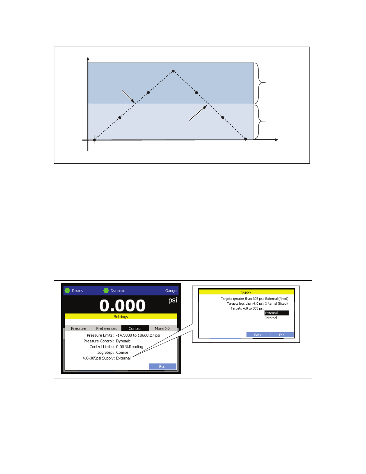
Setup
Configure the Pressure Supply 2
Automatic Pressure Supply Selection Example
Test Point 4
(720 psig)
At 305 psig,
Controller Switches
>305 psig
APPLIED PRESSURE
4 psig to
305 psig
to External Source
Test Point 2
(240 psig)
Test Point 3
(480 psig)
At 305 psig,
Controller Reverts Back to
to Internal Source
Test Point 5
(480 psig)
Test Point 6
(240 psig)
External Supply
(Intensifier or Nitrogen
Cylinder)
Internal Supply
(Electric Motor)
Test Point 1
(ATM)
Test Point 7
(ATM)
Figure 2-3. Automatic Supply Switch Example
Change the Supply setting as follows (see Figure 2-4).
From the Main menu:
1. Select
2. Select
Supply: in the Main menu to open the supply selection menu.
External or Internal.
Through the Settings menu:
1. From the Main menu, select to open the settings menu.
2. Select the
3. Select
4. Select
Control tab.
4.0-305psi Supply.
External or Internal.
Time
gxj064.eps
Figure 2-4. Supply Selection
gxj053.eps
2-7
Page 40
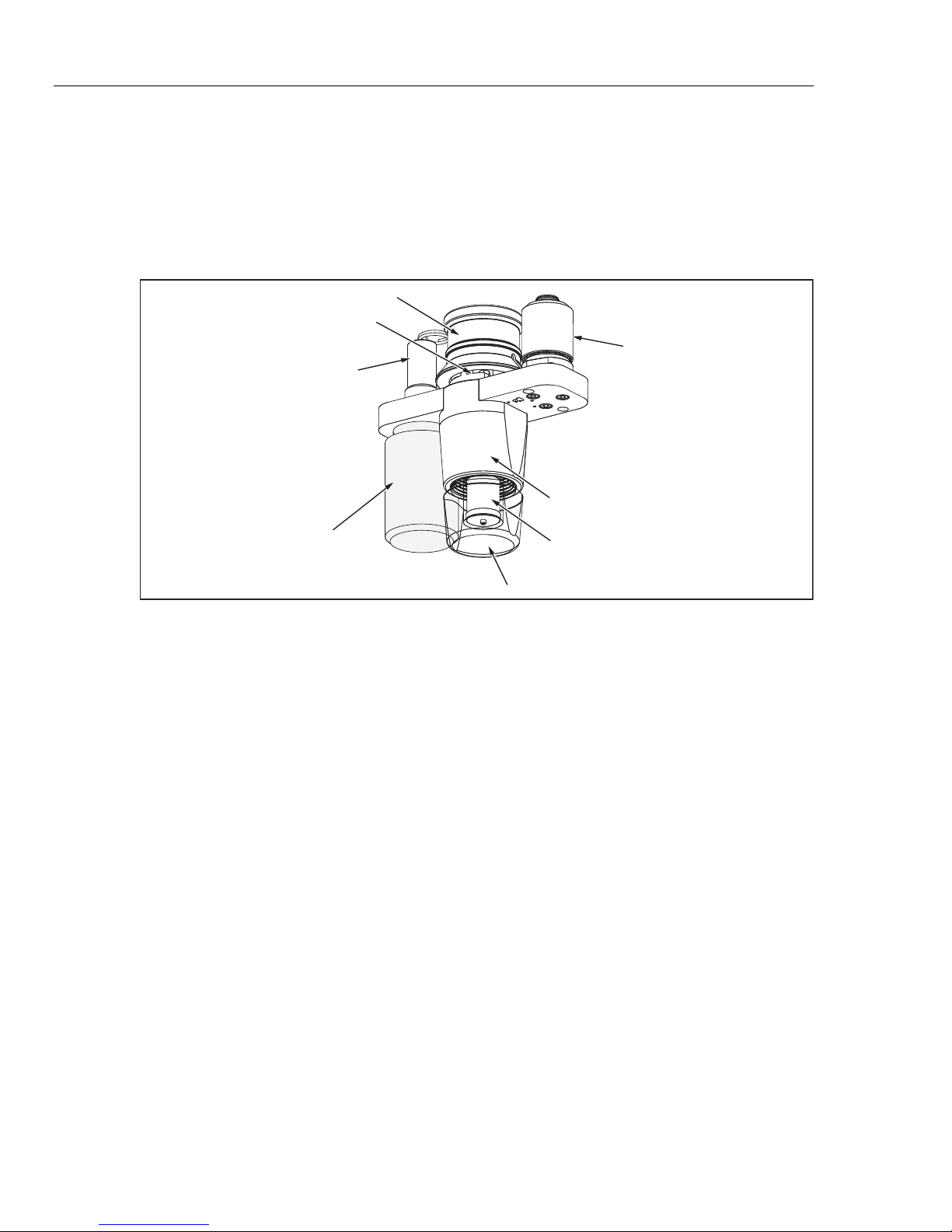
4322
Operators Manual
Contamination Prevention
To prevent damage to the Controller from contaminates that can be in the UUT and hoses
such as water, dirt, oil and grease, the Controller is equipped with a Contamination
Protection System (CPS). The CPS consists of an electronically controlled vent, a male
and female QC fitting, a filter, and a purge port with a 60 ml plastic waste container (see
Figure 2-5). The UUT connects directly to the CPS and does not require a separate inline
connection.
Cap Handle
Control Vent Valve
TEST Port
HOSE PURGE Port
(Male QC Fitting)
Plastic Waste
Container
Fine Coalescing Filter
(not shown)
Coarse Coalescing Filter
(Female QC Fitting)
Access Cover (shown transparent for clarity)
gxj023.eps
Figure 2-5. The CPS
The Accessory Kit includes two separate sets test hoses and two CPS accessories. These
two components are each identified by either a blue or orange mark as shown in
Figure 2-6. The materials and construction of each set is identical, but the suggested use
is for the blue set to be the "clean" configuration (used for UUTs that operate in gas, fresh
water, freons, etc.) and the orange set to be the "dirty" configuration (used for UUTs that
operate in salt water, oils, hydraulic fluids, and fuels).
The division of fluid service for these configurations is the decision of the user. Before a
calibration is started, select a configuration and only use that configuration to calibrate
UUTs that contain similar fluids or gasses.
2-8
Page 41
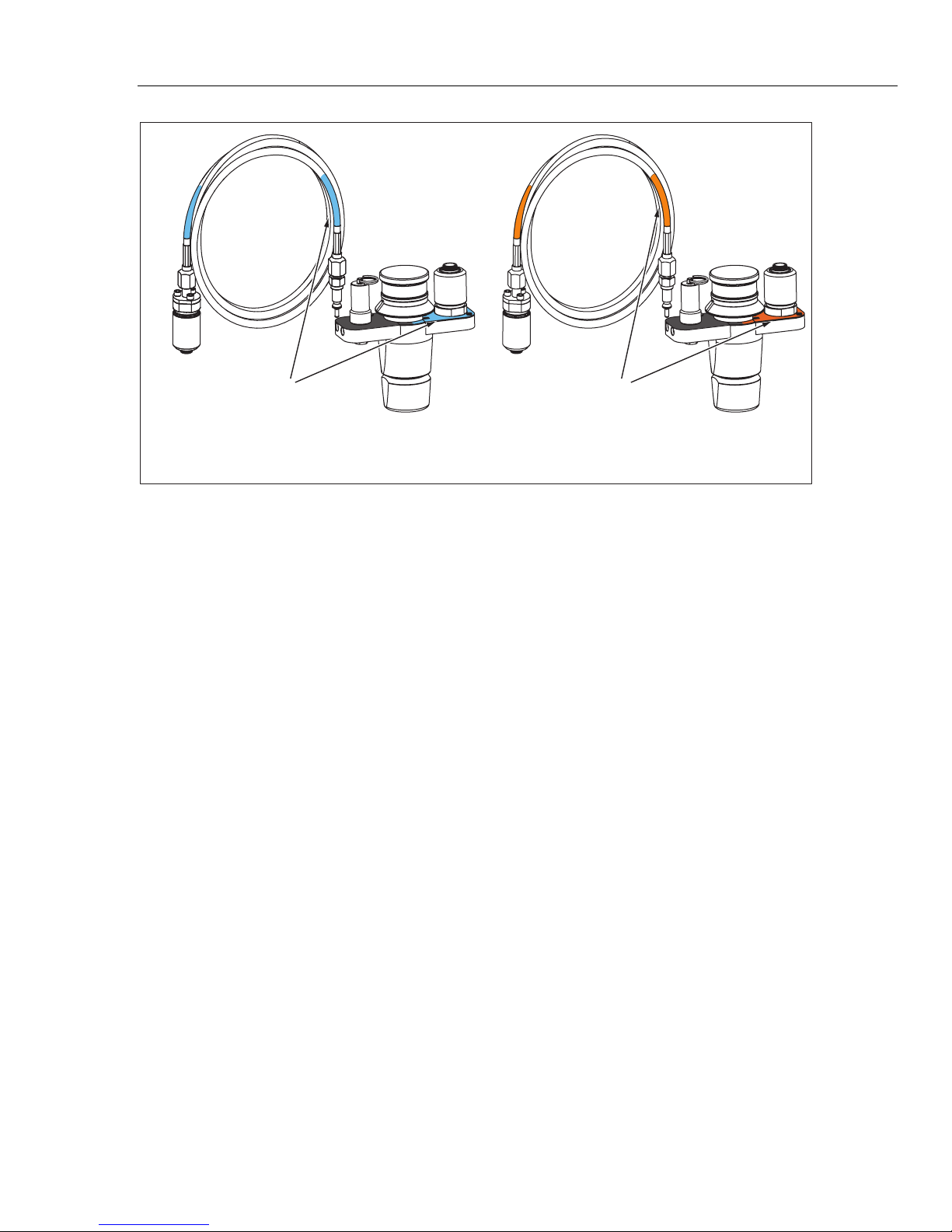
Setup
Contamination Prevention 2
Blue Orange
Figure 2-6. CPS Configurations
gxj007.eps
Install the CPS
1. Choose a blue or orange marked CPS to use.
2. Unscrew the bottom CPS access cover and check to make sure the coalescing filters
are installed and tight. Reinstall the CPS access cover when finished.
3. Carefully put the CPS into the Controller. Make sure the pressure-lock fittings lock
and the CPS is fully seated (see Figure 2-7).
To prevent damage to the Controller, drain as much fluid as
possible out of the UUT before it is connected to the
Controller. Empty the waster container after each test.
The CPS is held in place by a pair of pressure lock fittings that are locked
when pressure is applied to prevent CPS removal. When pressure is not
applied, the CPS can be easily lifted from the Controller (see Figure 2-7).
4. Connect the male end of the hose or UUT QC adaptor to the TEST port on the CPS.
To prevent damage to the UUT, always use the test hose
with the same color marking as the CPS. See “UUT CrossContamination Prevention” on page 2-8.
Caution
Note
Caution
2-9
Page 42
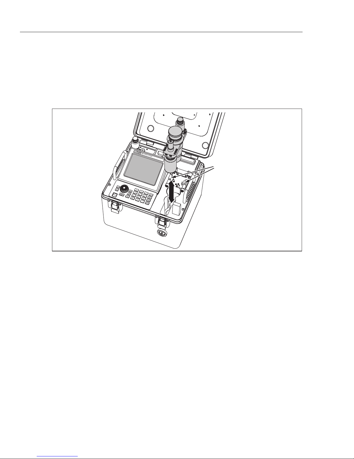
4322
Operators Manual
Remove the CPS
1. Push on the Controller to relieve pressure on the CPS and QC fittings.
2. Purge the test hose (see “Hose Purge” in Chapter 3).
3. Disconnect the test hose from the TEST port.
4. Hold the top of the CPS and pull upwards to remove.
5. Clean the CPS and test hose and put them in the Accessory Kit.
Pressure-Lock Fittings
Figure 2-7. CPS Installation and Removal
Connect the Handheld Control Accessory
Connect the Handheld as follows:
1. Open the rubber communication module protective cover on the Controller.
2. Connect one end of the cord to the “Handheld” port on the Controller.
3. Connect the other end of the cord to the Handheld (see Figure 2-8).
gxj022.eps
2-10
Page 43

Setup
Connect to a Unit Under Test (UUT) 2
Handheld
Control
Push into Terminal to Connect
Pull on Locking
Collar to Disconnect
Controller
Figure 2-8. Handheld Control Connection
Disconnect the Handheld as follows:
1. Remove the cord from the Controller and the Handheld Control. Pull back the collar
on the connector to disengage the collar lock.
Caution
To prevent damage to the cord or the product, do not pull
on the cord to disconnect it from the Controller or the
Handheld. Pull back on the collar on the connector to
properly disconnect the cord.
2. Clean the Handheld Control and store in the Accessory Kit or the lid of the
Controller.
3. Close the rubber communication module protective cover on the Controller.
Connect to a Unit Under Test (UUT)
Use the procedure in this section to prepare a UUT for calibration.
1. Remove the pressure fitting on the UUT so that a QC fitting can be installed later in
this procedure.
2. Drain the UUT of excessive fluids (if necessary).
gxj057.eps
3. Find the correct size QC fitting inside the Adapter Kit (see “Accessory Kit Items” in
Chapter 1).
2-11
Page 44
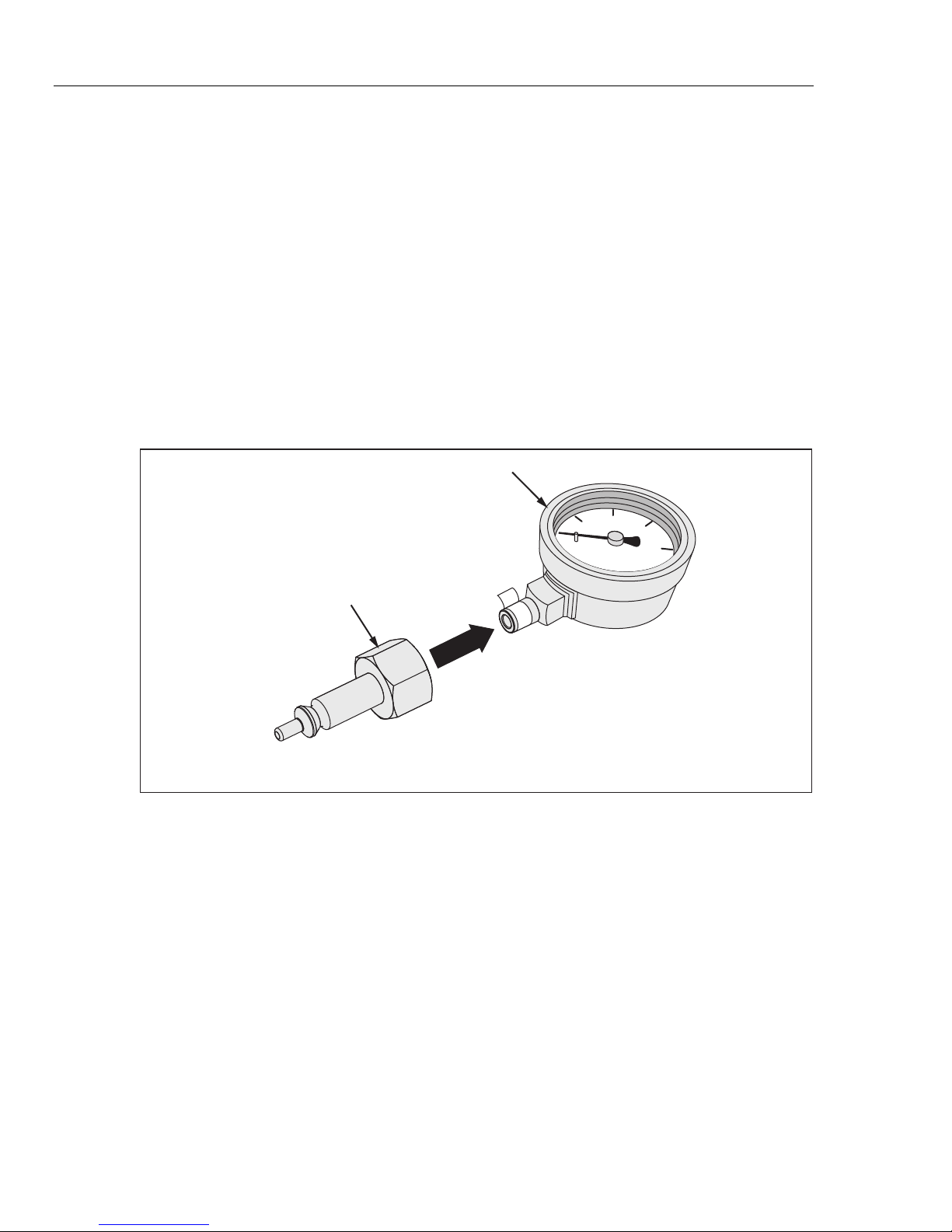
4322
Operators Manual
Caution
To prevent damage to the UUT, make sure to select the correct
size adapter fitting with the correct thread type. Ensure that all
hardware used is rated to adequate working pressure, and that
all equipment is in proper working order (for example, no
cracks or stripped threads).
Warning
To prevent injury, only trained personnel should make
connections. Always use standard and/or manufacturer
recommended procedures to connect each device.
4. Wrap the threads of the QC fitting with Teflon tape (if required) then put the fitting
on the UUT (see Figure 2-9).
Note
Failure to properly tighten the adapter fitting can result in a leak.
UUT
200
100
Adapter
Figure 2-9. UUT Connection Example
300
400
50
5. Connect the female end of the test hose to the male QC fitting on the UUT.
6. Connect the male end of the test hose to the TEST port on the Controller.
Note
The test hose is not required for every test. In some cases, the adaptor can
be connected to the UUT can be mounted directly into the TEST port.
gxj044.eps
7. Turn on the Controller.
8. Purge the hose to ensure cleanliness and to prevent contamination. Use the
instructions in “Hose Purge” in Chapter 3.
9. Perform a leak test. Use the instructions in “Leak Test” in Chapter 3. If a leak is
found, correct the leak and attempt the leak test again.
2-12
Page 45
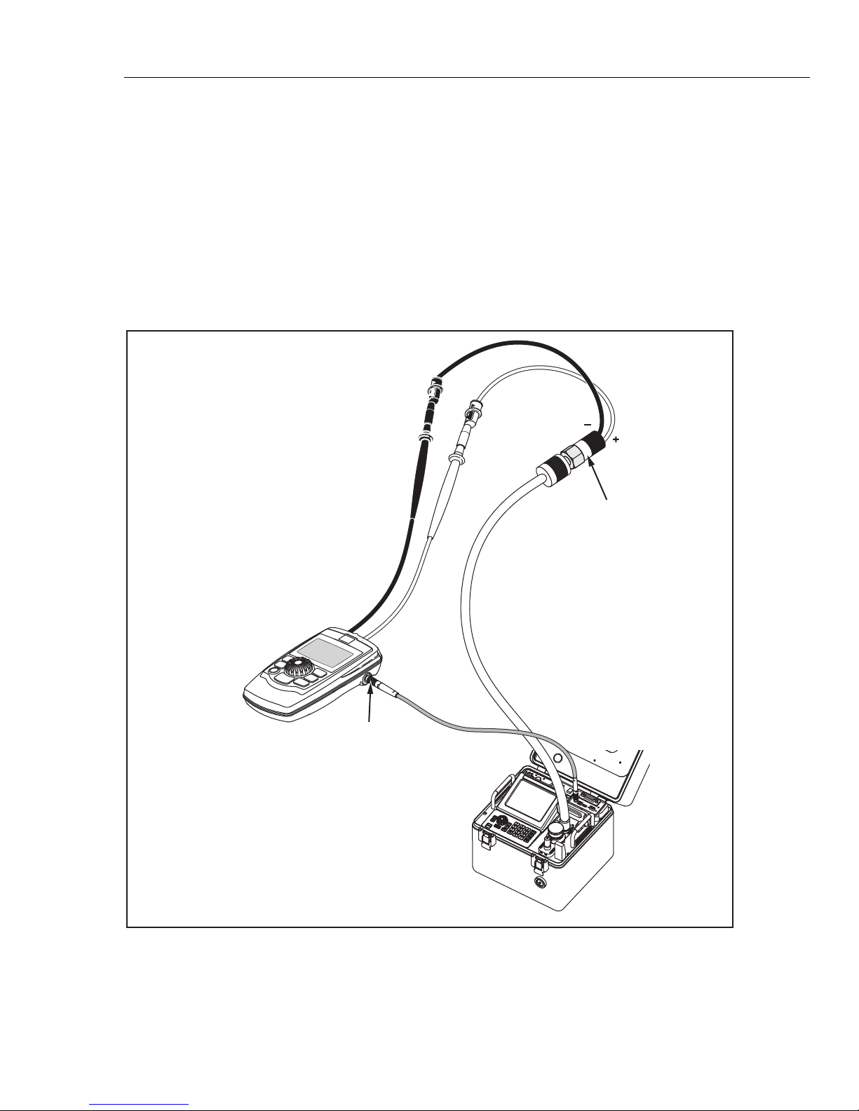
Setup
Connect to a Unit Under Test (UUT) 2
Caution
To prevent damage to a UUT, do not over tighten the QC fitting.
If a leak is located between the QC fitting and UUT, make sure
the correct adapter is used.
Additional Steps For Pressure Switches Only:
10. Connect the Handheld to the Controller.
11. Connect the black lead from the Handheld Control to the negative terminal (-) on the
pressure switch. See Figure 2-10.
12. Connect the red lead from the Handheld Control to the positive terminal (+) on the
pressure switch. See Figure 2-10.
Handheld
Control
Push into Terminal
to Connect
Pull on Locking
Collar to Disconnect
Controller
Electronic
Pressure
Switch
Figure 2-10. Pressure Switch Lead Connections
gxj080.eps
2-13
Page 46
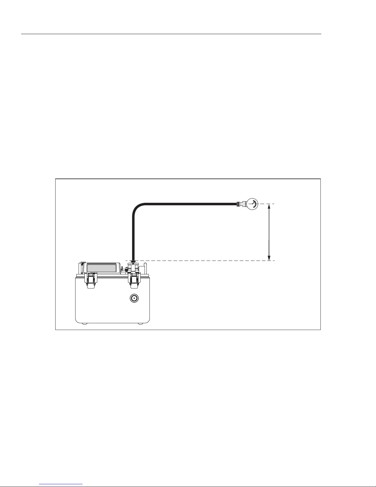
4322
Operators Manual
Make a Head-Height Correction
For calibration of a UUT at a different height than the Controller, it is necessary to make
a head-height correction. The head-height correction is the vertical difference between
the reference plane of the UUT to the top of the Test port on the Controller in inches or
centimeters.
Note
If the UUT does not have a reference plane marking, use the bottom of the
UUT as the reference plane.
After the measurement is made, the measurement value is entered into the Controller.
Use a positive (+) value if the UUT is above the Controller and a negative (-) value if the
UUT is below (see Figure 2-11).
Caution
Failure to make a head-height correction can result in an
inaccurate calibration.
Head-Height Correction Example
UUT
Reference Plane
Controller
Figure 2-11. Head-Height Correction Example
Make a Head-Height Correction from the Main menu as follows:
1. Select
2. Key in
Head on the Main menu to open the Head menu.
Height, Unit, and Medium.
3. Select to save and close the menu.
Make a Head-Height Correction through the Settings menu as follows:
Correction
Mesurement
Top of the TEST
Port QC
gxj026.eps
1. From the Main menu, select to open the settings menu.
2. Select the
3. Key in
Pressure tab.
Height, Unit, and Medium.
4. Select to save and close the menu.
2-14
Page 47
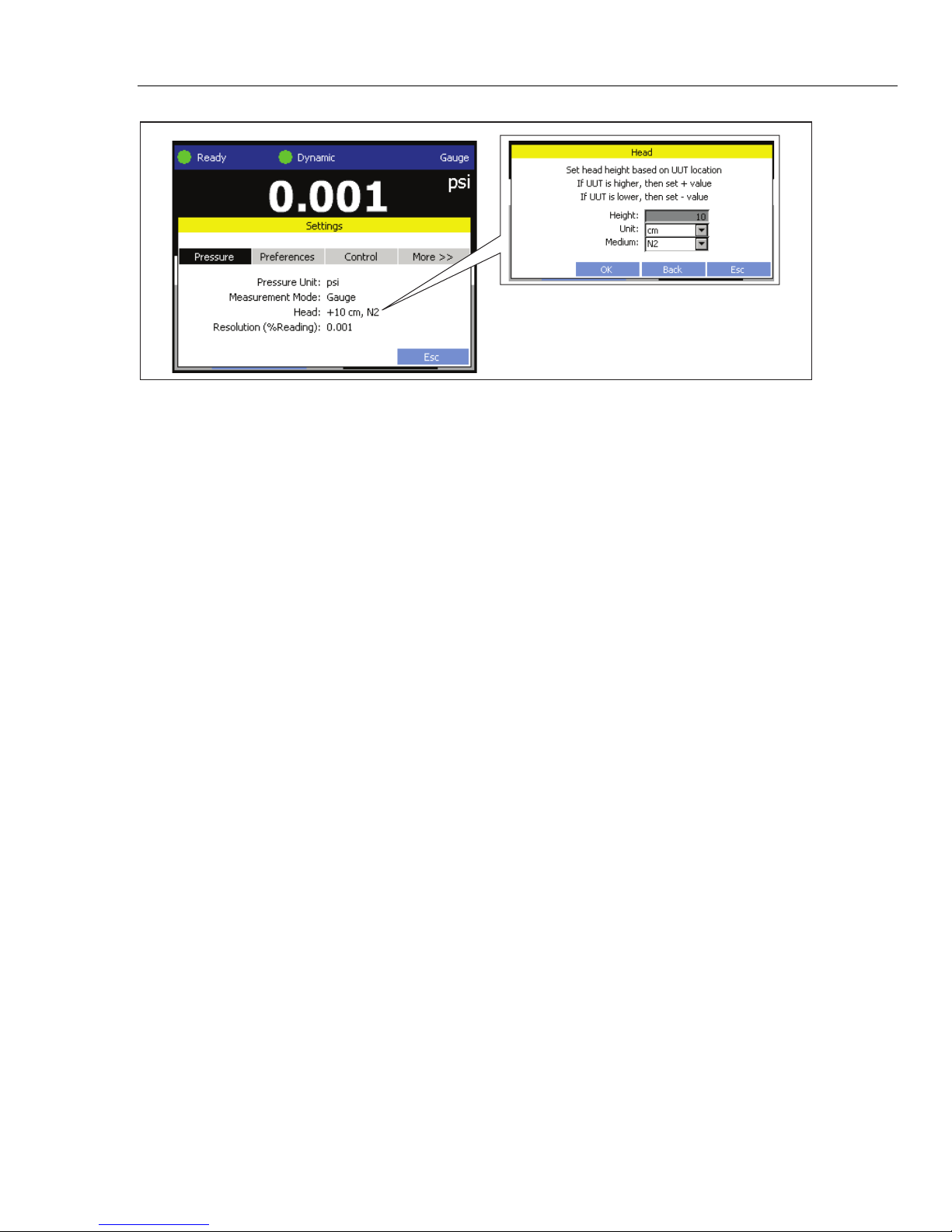
Setup
Controller Settings 2
Figure 2-12. Head Menu
gxj067.eps
Controller Settings
The Settings Menu
The Settings menu screen supplies quick access to the six setting submenus (Table 2-1).
The submenus are referred to as “tabs” such as “the Preferences tab” or “the Pressure
tab”. The Settings menu can only show three tabs at a time. Use the “
cycle through the tabs not shown.
More >>>” tab to
Note
Test Sequences contain settings such as Measurement Mode and Unit of
Measure that are also defined in the Settings menu. During a Test
Sequence, the Controller temporarily changes to the settings contained in
the test file. After the test is complete, the Controller automatically reverts
back to the settings set in the Settings menu.
2-15
Page 48
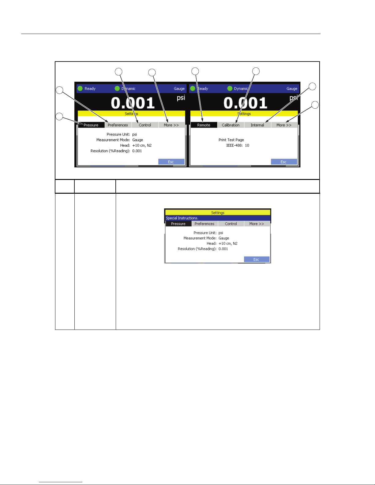
4322
Operators Manual
Table 2-1. Settings Menu
3
2
1
4
5
Item Tab Function
Contains basic pressure settings.
6
7
4
gxj015.eps
Pressure
Pressure Unit – Set the unit of measure. See “Unit of Measure” in Chapter 3 for a
list of units available. Additional custom pressure units can be made.
Measurement Mode - Set the Measurement mode. See “Measurement Modes” in
Chapter 3.
Head - Set the head-height correction. See “Make a Head-Height Correction” in
Chapter 2.
Resolution (% of Reading) – Set the resolution of the measurement on the Main
menu. See “Measurement Resolution” in Chapter 3.
2-16
Page 49
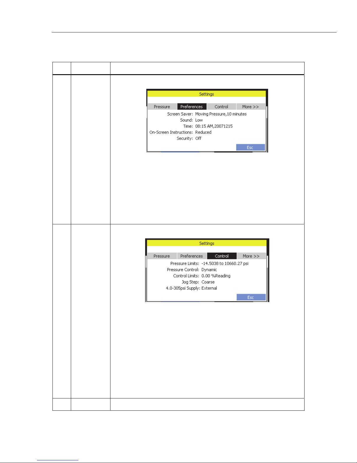
Setup
Controller Settings 2
Table 2-1. Settings Menu (cont.)
Item Tab Function
Contains general system preferences.
Preferences
Control
More >>>
Screen Saver – Set when and what type of screen saver to display.
Sound – Set the system sound to Off, Low, Medium, or High. See “Sounds and
Alarm Volume” on page 2-21.
Time – Set the date and time. The time format can be changed from this menu.
On-Screen Instructions – Changes the amount of helpful text shown in the
message bar on the main menu. Standard shows all helpful text and Reduced
shows a minimalized amount of helpful text.
Security – Set the Controller security to On or Off. See “Security Levels” on
page 2-20.
Contains pressure control preferences.
Pressure Limits – Set the upper and lower pressure limits. See “Set the
Pressure Limits and Control Limits” in Chapter 3.
Pressure Control – Set the Pressure Control Mode. See “Change the Pressure
Control Mode” in Chapter 3.
Note
Dynamic Control with Jog Approach is only available as part of a Test Sequence.
Control Limits – Set the Control Limits. See “Pressure Limits and Control Limits”
in Chapter 3.
Jog Step – Set the Jog Step percentage. See “Jog Step Pressure Up or Down” in
Chapter 3.
4.0-305psi Supply - Set the default supply to use in the 4 psig to 305 psig range.
See “Internal and External Supply Setting” on page 2-6.
Cycle through the tabs not shown.
2-17
Page 50
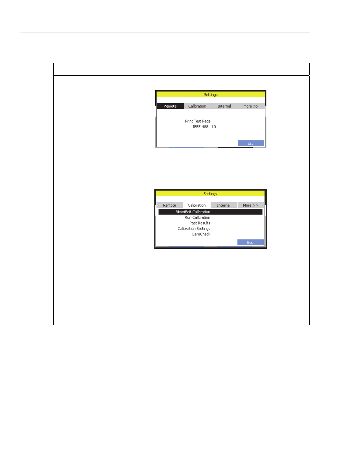
4322
Operators Manual
Item Tab Function
Remote
Table 2-1. Settings Menu (cont.)
Contains remote operation configuration settings.
Print Test Page – Send a test page to the connected printer to test the
connectivity.
IEEE-488 – Set the IEEE address.
Contains Controller calibration settings and information.
Calibration
View/Edit Calibration – View or edit the calibration coefficients. See the 4322
Service Manual for calibration information and procedures.
Run Calibration – Opens a Calibration menu with tools to calibrate the
Controller. See Chapter 7 or the 4322 Service Manual for calibration information
and procedures.
Past Results – View past calibration results.
Calibration Settings – Set a custom calibration tolerance and apply it to a
module. See Chapter 7.
BaroCheck – See “AutoZero and BaroCheck” in Chapter 3.
2-18
Page 51
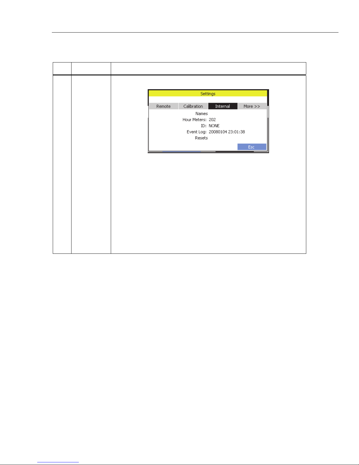
Setup
Controller Settings 2
Table 2-1. Settings Menu (cont.)
Item Tab Function
Contains maintenance settings.
Names – The Controller has a UUT library that can store the names of commonly
Internal
used UUT names and UUT manufacturers. This feature allows UUTs to be quickly
loaded into tests when tests are configured.
Hour Meters – Opens a menu that shows the internal piston pump hours
(resettable), how many hours that system has been pressurized(total and since
last calibration), and total amount of hours that Controller has been turned on.
See Chapter 6 for more information and reset instructions.
ID – Set an alpha-numerical identification to identify the Controller. See
“Controller Identification” in Chapter 6.
Event Log – Event log that tracks and records errors and important system
events such as calibrations and overpressures. See “Event Log” in Chapter 6.
Resets – A series of reset functions for maintenance personnel to reset the
Controller settings. See “Reset Controller Settings” in Chapter 6.
2-19
Page 52
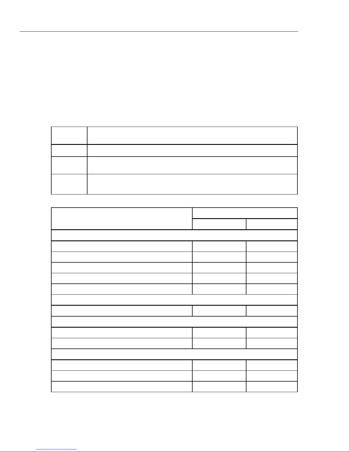
4322
Operators Manual
Security Levels
The Controller is equipped with three user-level access security levels (Off, Low, and
High) to protect from undesired changes to the settings (see Table 2-2). The Controller
comes from the factory with the security level set at Low. A Low level restriction is
recommended for normal day-to-day operations.
Caution
To prevent configuration changes to the metrological
information and calibration information, it is recommended that
the low security level be set at all times.
Table 2-2. Security Levels
Security
Level
Off
Low
High
Clear the Event Log NO NO
Change the Screen Saver YES NO
Change the Sound Volume YES NO
Change the System Time YES NO
Reset all Settings NO NO
No security applied.
Protects the specific metrological information and calibration information settings. Low
security is the default setting.
Protects all operating parameters. It is intended to minimize user choices, for example to
perform repeated identical calibrations under consistent conditions.
Table 2-3. Security Level Diagram
Function or Area
General Settings
Definition
Changes Allowed?
Low Security High Security
Change or Reset Pressure Units YES NO
Barometer Calibration NO NO
Auto-Calibration NO NO
Make a New Test YES NO
Edit or Change a Test YES NO
Delete a Test YES NO
2-20
Pressure Settings
Calibration Settings
Test Management
Page 53
Setup
Controller Settings 2
Change the security level as follows:
1. From the Main menu, select to open the settings menu.
2. Select the
Preferences tab.
3. Select a security level.
4. Select to save and close the menu.
Sounds and Alarm Volume
The Controller uses different sounds to audibly notify the user of actions on the
Controller (see Table 2-4). The volume of the sound is user configurable and can be
adjusted in the settings menu to Off, Low, Medium, or High.
Note
Setting the volume to Low or Off does not disable the audible alarm.
Table 2-4. Sounds
Action Sound
Valid Key Push High frequency, single beep
Invalid or Incorrect Key Push Low frequency, single beep
Leak Check Complete Three high frequency, single tones
The Controller has a loud audible alarm that sounds when an overpressure or a limit is
exceeded (see Table 2-5). The alarm is not a general sound and sounds regardless of the
volume settings.
Table 2-5. Alarms
Action Sound
Upper or Lower Limit Exceeded Continuous high frequency, single beeps until acknowledged
Overpressure Eight second, high-frequency tone
Change the sound volume as follows (see Figure 2-13):
1. Select on the Main menu.
2. Select the
3. Select
Preferences tab.
Sound to open the sound menu.
4. Select a volume level.
2-21
Page 54
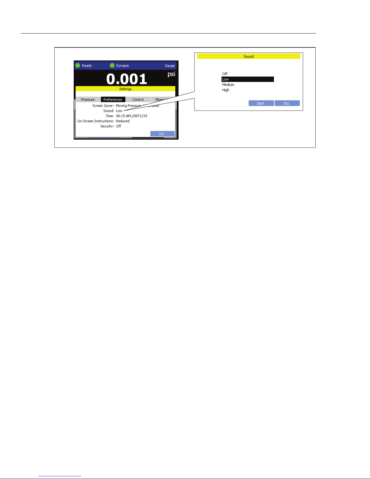
4322
Operators Manual
Figure 2-13. Sound Menu
gxj066.eps
2-22
Page 55

Chapter 3
Controller Operation
Title Page
Introduction ........................................................................................................ 3-3
Turn On the Controller ...................................................................................... 3-3
Operating Modes ................................................................................................ 3-3
Warm-up ............................................................................................................ 3-3
Common Navigation Buttons ............................................................................ 3-4
The Main Menu ................................................................................................. 3-4
Set and Control Pressure .................................................................................... 3-6
Set Target Pressure ........................................................................................ 3-8
Interrupt Pressure Control ............................................................................. 3-8
Pressure Control Modes ................................................................................ 3-8
Dynamic Control Mode ............................................................................. 3-9
Dynamic Control Mode with Jog Approach ............................................. 3-10
Static Control Mode .................................................................................. 3-11
Set the Pressure Limits and Control Limits ................................................... 3-12
Pressure Limits (Upper and Lower) .......................................................... 3-12
Control Limits (Hold and Stability) .......................................................... 3-13
Pressure Control Functions ............................................................................ 3-14
Jog Step Pressure Up or Down .................................................................. 3-14
Vent the Controller .................................................................................... 3-15
Abort for Emergency Pressure Relief ....................................................... 3-15
Measurement Settings and Limits ...................................................................... 3-16
CalCheck Function ........................................................................................ 3-16
AutoZero and BaroCheck .............................................................................. 3-16
Measurement Indicator .................................................................................. 3-18
Measurement Modes ..................................................................................... 3-18
Measurement Resolution ............................................................................... 3-19
Unit of Measure ............................................................................................. 3-20
UUT Tolerance Limit .................................................................................... 3-22
Controller Tools ................................................................................................. 3-22
System Purge ................................................................................................. 3-22
Hose Purge..................................................................................................... 3-23
Leak Test ....................................................................................................... 3-24
Exercise ......................................................................................................... 3-25
Test a UUT ......................................................................................................... 3-26
The Test Menu ............................................................................................... 3-27
Test Sequences .............................................................................................. 3-28
Test Sequence Actions .................................................................................. 3-28
Find a Saved Test ...................................................................................... 3-29
3-1
Page 56

4322
Operators Manual
Edit a Test ................................................................................................. 3-29
Copy a Test ............................................................................................... 3-29
Delete a Test .............................................................................................. 3-29
Make a New Gauge/Transducer Test ........................................................ 3-30
Make a New Pressure Switch Test ............................................................ 3-33
Run a Test Sequence ..................................................................................... 3-35
View Test Results .............................................................................................. 3-37
Print a Test Report ............................................................................................. 3-38
3-2
Page 57
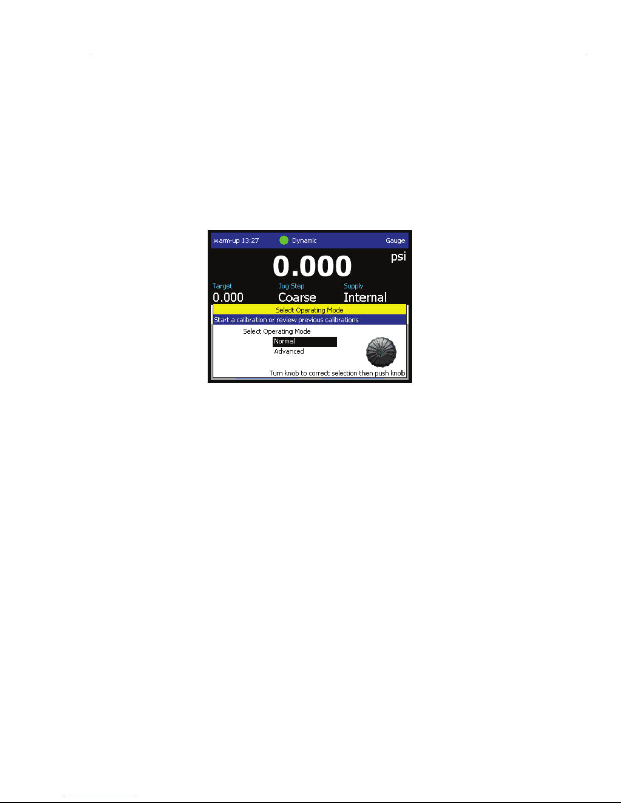
Controller Operation
Introduction 3
Introduction
This chapter contains instructions on how to operate the Controller.
Turn On the Controller
To turn on the Controller, connect the mains power cord and push the toggle the switch to
the (I) position. The system initializes and a system startup screen shows the model
number, serial number, and firmware version.
After the start-up initialization is complete, the startup screen disappears and the
Operating Mode Selection menu opens and prompts the operator choose to use the
Normal or Advanced operating mode (see Figure 3-1 and refer to “Operating Modes” ).
Operating Modes
The Controller has two operating modes:
• The
Normal operating mode opens a simplified test menu that lets the operator
quickly test a UUT. In the simplified test menu, the on-screen instructions guide the
operator through setting up or selecting a test and running it in minimal time. When
the test is finished, the operator can quickly review and print the test results. In the
Normal mode, the operator still has the ability to use the Controller tools such as
System or Hose Purge, Leak Test, and Exercise as part of the test sequence. This
chapter does not provide instructions on how to step through the guided test, but does
provided specific guidance on pressure control and measurement settings contained
in the Normal operating mode.
• The
Advanced operating mode opens the Main menu where the operator can choose
from a variety of on-screen functions and menus such as the Test and Settings menus.
See “The Main Menu” for more information on the menus and features that can be
opened from the Main menu. This chapter provides guidance and information on the
different settings and parameters that can be adjusted from the Main and subsequent
menus and also how to test a UUT using the Advanced operating mode.
Warm-up
For the Controller to perform to the specifications listed in Chapter 1, a 15 minute warmup period is required after the Controller is turned on (additional ambient temperature
acclimation may be required, see “Warm-up” in the Specifications section in Chapter 1).
When turned-on, a countdown timer appears in the upper left corner of the main menu
that shows the remaining warm-up time (see Figure 3-1). The countdown timer will
disappear after the 15 minute warm-up is complete.
Figure 3-1. Startup Screen Example
gxj027.eps
3-3
Page 58
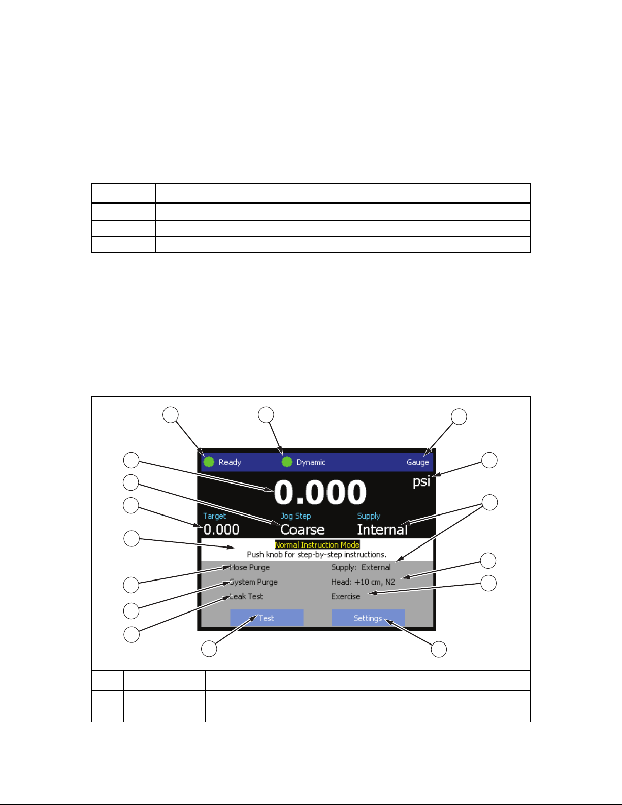
4322
Operators Manual
Common Navigation Buttons
To navigate the menus, use the on-screen navigation buttons on the bottom of each menu.
See Table 3-1 for information and a list of the common navigation buttons found on most
menus. To move around the menus, use the Dual-Purpose Push Button/Rotary Dial or the
or keys. To make a selection, push the Dual-Purpose Push Button/Rotary or .
See “Controller Indicators and Controls” in Chapter 1 for more information on each key.
Table 3-1. Navigation Buttons
Button Navigation Function
Saves changes and navigates to the next menu.
Cancels changes on current menu and navigates back to the last menu.
Cancels all changes and navigates back to the Main menu.
The Main Menu
The Main menu is where all functions and menus are accessed. Refer to Table 3-2 for
information about each item.
Most items on the Main menu are selectable and opens the related
user-configurable options and settings.
2
1
16
15
Note
Table 3-2. Main Menu
3
4
5
6
14
13
12
11
10
Item Name Function
Measured
Pressure
3-4
7
8
9
Shows the current applied pressure to the UUT and opens a menu that
contains resolution settings from 1.0 to 0.0001 % of reading.
gxj013.eps
Page 59
Controller Operation
The Main Menu 3
Table 3-2. Main Menu (cont.)
Item Name Function
Shows when the pressure is stable and ready for a measurement. The
indications are: (Green) Ready, (Yellow) Near Ready, (Red) Not Ready.
Measurement
Indicator
This area also shows important notifications such as the warm-up
countdown and also the Cal Check indicator if there is an issue with a
module. See “Warm-up” on page 3-3 and “CalCheck Function” on
page 3-16.
See “Measurement Indicators” on page 3-22.
Pressure Control
Mode
Measurement
Mode
Unit of Measure
Supply
Head-height
Correction
Exercise
Settings Menu
Test Menu
Leak Test
System Purge
Hose Purge
Instructions
Target Pressure
Shows the active control mode and opens a menu to configure the control
mode parameters. The indications are: Dynamic, Dynamic: jog approach,
and Static. When pressure control is active, the indictors are animated. See
“Pressure Control Modes” on page 3-8.
Shows the active measurement mode and opens a menu to change the
measurement mode. See “Change the Measurement Mode” on page 3-16.
Shows the unit of measure and opens a menu to change the unit of
pressure. See “Make or Change a Unit of Measure” on page 3-20.
Opens a menu to set the default pressure source for targets between 4 and
305 psig. See “Set the Internal and External Supply Setting” in Chapter 2.
Shows the current head-height correction and opens a menu that contains
user-configurable settings for head height, units, and type of gas in use. See
“Make a Head-Height Correction” in Chapter 2.
Opens a menu to configure and exercise a UUT. See “Exercise” on
page 3-25.
Opens a two-page settings menu to configure the Controller. See “The
Settings Menu” in Chapter 2.
Opens the test menu to configure and perform a test on a UUT. See “About
the Test Menu” on page
Opens a menu to configure and perform a leak test on the system. See
“Leak Test” on page 3-27.
Opens a menu to configure and purge the plumbing in the Controller. See
“System Purge” on page 3-22.
Opens a menu to configure and purge a hose. See “Hose Purge” on
page 3-23.
Shows helpful on-screen instructions. This can be set to Normal or
Reduced. See “The Settings Menu” in Chapter 2.
Shows the current target pressure value and opens a menu to set a target
pressure. See “Set Target Pressure” on page 3-6.
Jog Step
Shows the Jog Step setting. The two Jog Step settings are Coarse and
Fine. See “Jog Step Pressure Up or Down” on page 3-14.
3-5
Page 60

4322
Operators Manual
Set and Control Pressure
To measure pressure, the Controller uses four Pressure Transducer Modules (pressure
module). A pressure module (shown in Figure 3-2), is a serviceable and replaceable
pressure measurement component installed behind the display. It allows for easy access
to calibrate or replace a failed pressure module. Each pressure module has an assigned
slot with a specific pressure range.
The Controller reads the pressure module information and checks each pressure module
on Controller startup. If a pressure module is out of tolerance or in the incorrect slot, the
Controller shows an error on the Startup screen and pressure control is disabled until the
condition is corrected.
Each pressure module has three internal sensor elements that make three separate
measurements. The output of all three sensors are averaged to reduce total measurement
uncertainty. The three individual measurements are also constantly monitored and
compared against each other to ensure that they are indicating pressure within a certain
tolerance of each other. If one of the sensor elements measure a value that is unlike the
other two sensor elements measurements, the Controller shows “CalChk” on the top of
the Main menu to provide early warning of a potential out of tolerance condition (see
“CalCheck Function” on page 3-16).
Each pressure module is calibrated individually against an external reference. See the
calibration procedure in Chapter 7 or in the 4322 Service Manual for calibration
instructions.
Use the information in the subsequent sections to set pressure, define limits, and perform
pressure functions.
A similar replaceable barometer module (shown in Figure 3-2), provides reference
pressure measurement over the barometric range. During normal use, the barometer
module reads atmospheric pressure through the ATM port on the front panel of the
Controller, and is not exposed to the pressure excursions seen by the pressure modules.
This limited use further improves the performance of the barometer module, providing
stable measurements for the AutoZero and BaroCheck functions (see “AutoZero and
BaroCheck” on page 3-16. The barometer is a serviceable and replaceable module that
must be regularly calibrated.
Read the subsequent sections for more information on the measurement indicators and
measurement modes. Refer to the 4322 Service Manual for maintenance time intervals,
calibration procedures, and replacement instructions.
3-6
Page 61
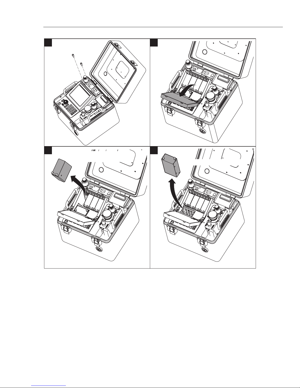
Controller Operation
Set and Control Pressure 3
1
3 4
Pressure Transducer Modules
(Pressure Modules)
2
Barometer Module
Figure 3-2. Pressure Transducer Modules and Barometer Removal
gxj079.eps
3-7
Page 62
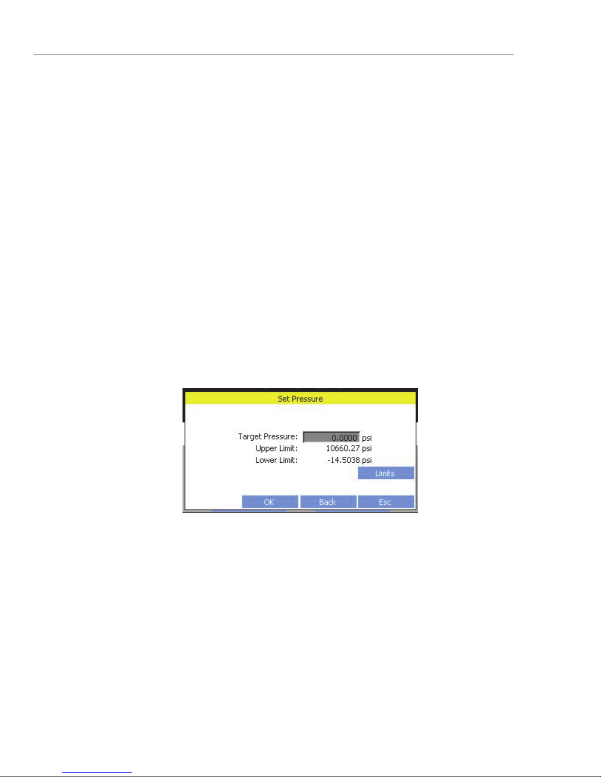
4322
Operators Manual
Set Target Pressure
Target pressure is the numerical pressure value the Controller controls pressure to when
commanded. When a target pressure is set, the Controller opens the internal pressure
valves and applies pressure to the UUT. As the pressure approaches the target value,
pressure control slows to prevent an overshoot. The Controller then uses the active
control mode to keep the pressure between the upper and lower hold limits (see “Pressure
Control Modes” on page 3-8).
Note
If the Controller is unable to control pressure or controls pressure poorly,
see the troubleshooting procedures in Chapter 4.
Set the Target Pressure as follows (see Figure 3-3):
1. Select
Target in the Main menu or push on the control panel to open the Set
Pressure menu.
2. Enter the Target Pressure
.
Note
The upper and lower pressure limits are shown for reference on the menu.
A target pressure entry that exceeds the current upper limit or that is out of
range will not be accepted as the target value. To change the limits, see
“Pressure Limits (Upper and Lower)” on page 3-12.
3. Push to start pressure control to the target pressure value.
4. When pressure control is active, use and to change the target pressure.
Figure 3-3. Set Target Pressure
gxj065.jpg
Interrupt Pressure Control
When pressure control is active, if or is pushed, the Controller pauses pressure
control and returns to the Main menu. The pressure is not vented from the system. To
resume pressure control, push and enter a target pressure then push .
To quickly stop pressure control and immediately vent pressure, push
Pressure Control Modes
The Controller offers three different control modes to set pressure: Static Mode sets the
target pressure and stops controlling, adjusting only when the measured pressure has
exceeded specific limits. Dynamic Mode sets the target pressure and constantly adjusts to
maintain the target. Dynamic Control with Jog Approach uses the same control as
Dynamic Mode, but pressure is set to a point short of the test point. The user then uses
the jog function to adjust pressure to the desired UUT reading.
The control mode to be used is selected in the settings and also as part of a test. When a
3-8
or .
Page 63
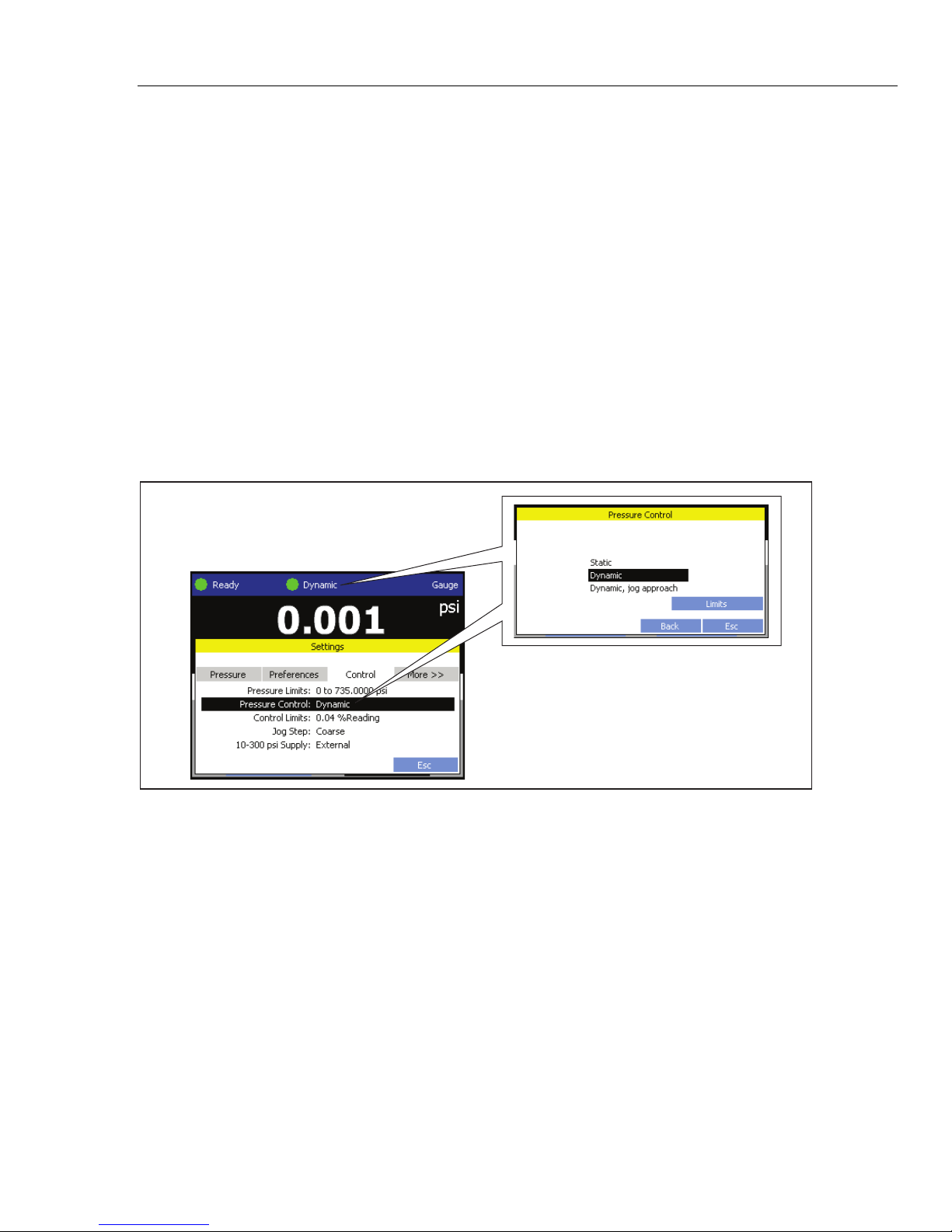
Controller Operation
Set and Control Pressure 3
target pressure is set on the Main menu, the Controller uses the control parameters found
in the control settings menu in the settings. If a test is run, the Controller uses the control
parameters selected and saved in the test setup.
The two modes have similar control parameters but control pressure differently (see
“Pressure Control Parameters, limits, and Functions”). Read the subsequent sections for
more information on each mode.
Change the Pressure Control Mode as follows (see Figure 3-4):
From the Main menu:
1. Select the
2. Select
Through the Settings menu:
1. Select on the Main menu then select the Control tab.
2. Select
3. Select
Control Mode Indicator.
Dynamic or Static.
Pressure Control to open the control mode settings.
Dynamic or Static.
Dynamic Control Mode
Dynamic Control sets the pressure to the target value then continuously controls pressure
to keep it at the target value (see Figure 3-5). Dynamic Control is beneficial for most
applications because it automatically compensates for changes to the system from
adiabatic affects and small leaks. Dynamic Control is the default control mode when the
Controller is turned on and shows in the user interface as
Dynamic Control generates a very small amount of pressure noise due to
continuous pressure control. The pressure noise is undetectable in most
UUTs. For high-end sensitive UUTs where pressure noise is a concern, use
Static Control for the test.
Figure 3-4. Control Mode Settings
Note
Dynamic.
•
gxj046.eps
3-9
Page 64
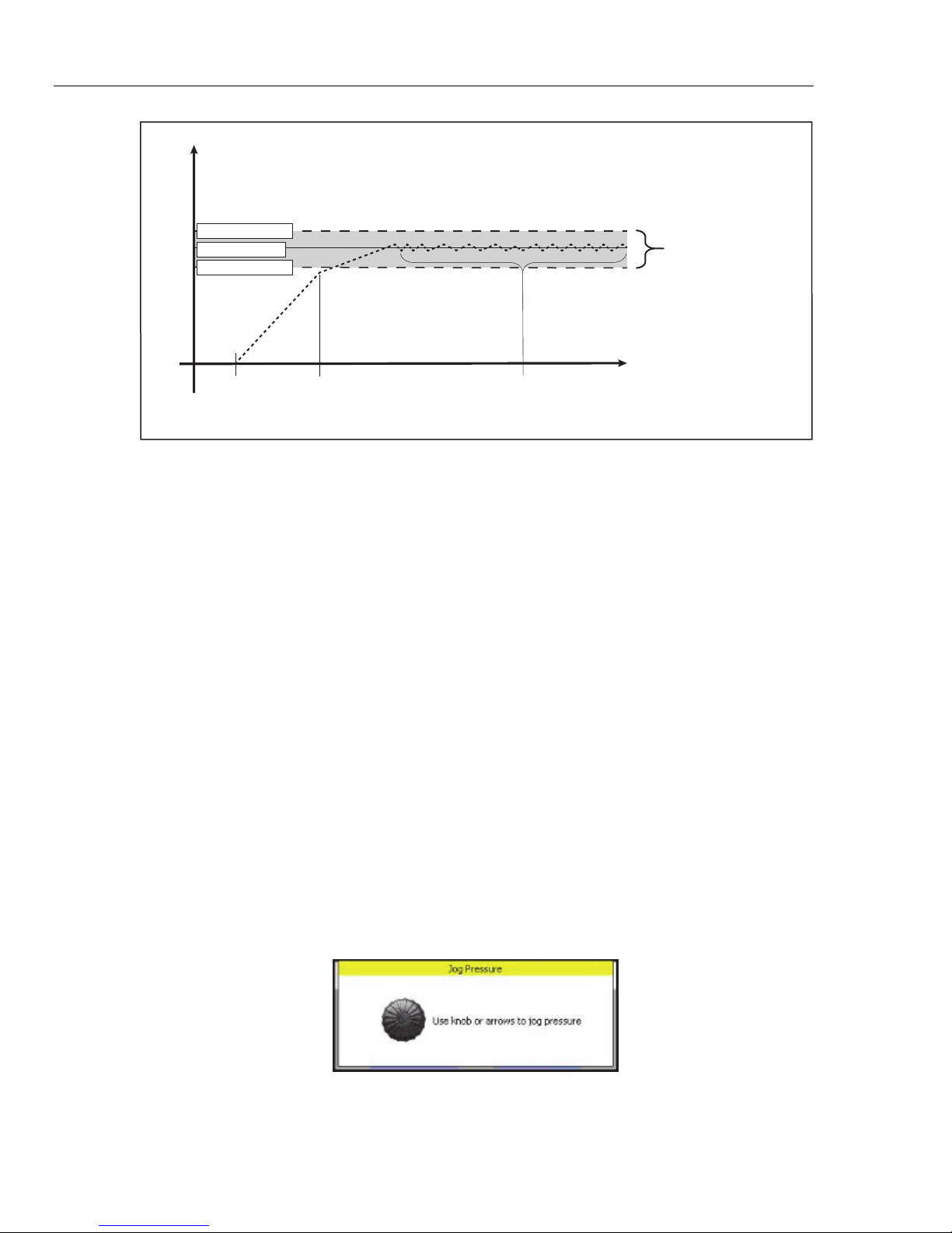
4322
Operators Manual
Dynamic Pressure Control
Upper Hold Limit
Target Pressure
APPLIED PRESSURE
Lower Hold Limit
Ta rg e t
Pressure
Set
Rate of Pressure
Decreased to
Prevent Overshoot
Figure 3-5. Dynamic Pressure Control Mode Example
Controller Continuously Makes
Dynamic Control Mode with Jog Approach
Dynamic Control with Jog Approach stabilizes the pressure at the target pressure and
then prompts the user to manually Jog the pressure to the set test point (see Figure 3-7).
For this mode and test, the user watches the UUT reading to visually set the pressure to
the test point.
This mode allows the user to manually set the pressure. As a result, it prevents UUT
reading interpolation and/or pressure overshoot. This is commonly known as a “Cardinal
Point” calibration, and is useful for calibration of analog dial gauges.
The 4322 has more resolution than the UUT and allows the set point to be adjusted up or
down so that the UUT pressure gauge needle is aligned on top of a cardinal mark. This
mode is the default setting for tests with the Pressure Gauge UUT Type selected and
shows in the user interface as
When the test is run, the Controller controls and stabilizes the pressure slightly above or
Dynamic with Jog Approach.
•
below the test set point pressure (above for descending test points, below for ascending
test points). The amount of pressure above or below the test set point is calculated as
follows:
Pressure Changes to Keep
Pressure as Close to the
Target Pressure as Possible
Time
The default dynamic hold
limit value is 0.1 % of
target pressure value or
10 % of the UUT
tolerance value,
whichever is greater. See
“Pressure Limits and
Control Limits” for more
information.
gxj011.eps
Ascending Target = Test Point Pressure – (2 x UUT Tolerance Value)
Descending Target = Test Point Pressure + (2 x UUT Tolerance Value)
After the pressure is stable, the Controller prompts the user to Jog up or down to the test
set point (see Figure 3-6). The user turns the rotary dial or pushes the and keys to
set the pressure to the set test point and make a measurement. This procedure is then
repeated for every test point for the remainder of the test.
3-10
Figure 3-6. Jog To Approach
gxj021.jpg
Page 65
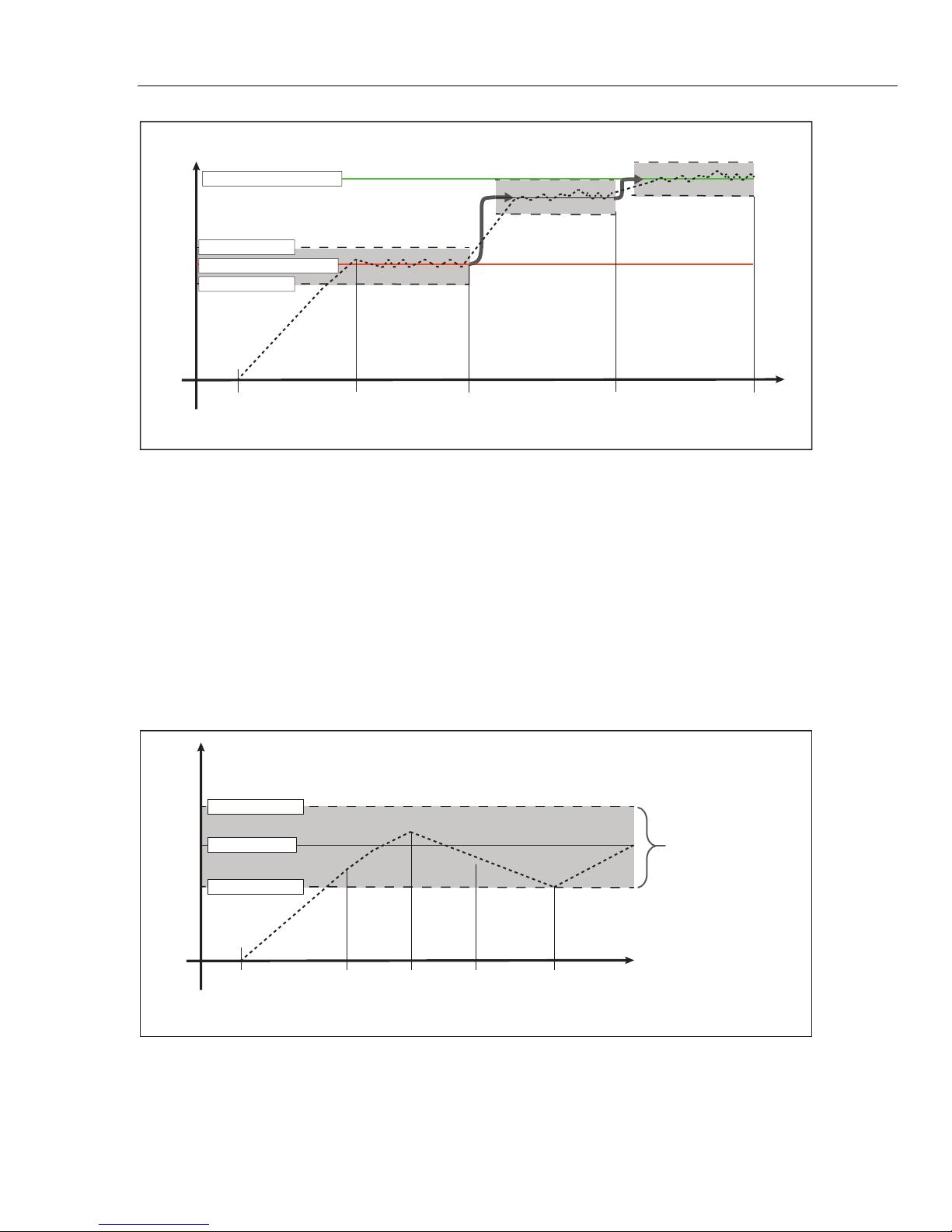
Controller Operation
Set and Control Pressure 3
Dynamic with Jog Approach Pressure Control
Set Test Point Pressure
Upper Hold Limit
Target Pressure
Lower Hold Limit
APPLIED PRESSURE
Target
Pressure
Set
Figure 3-7. Dynamic with Approach Control Mode Example
Static Control Mode
Static Control sets the pressure slightly above the target pressure value then turns off
active pressure control (see Figure 3-8). The pressure is allowed to naturally settle until it
exceeds the lower or upper hold limit. When the pressure exceeds a hold limit, the
Controller resets the pressure slightly above the target pressure value then turns off active
pressure control again to reestablish pressure within the hold limits. This pressure control
sequence repeats until the target pressure is changed or the test is complete.
The advantage of this control mode is that pressure can be set and measured without
noise from the pressure control system. Static Control shows in the user interface as
Static. A
O
and the rate of change of pressure is less than the stability limit.
Upper Hold Limit
Target Pressure
APPLIED PRESSURE
Lower Hold Limit
Pressure Stabilizes
at Target Pressure.
Jog Step Pressure to
Set Test Point Pressure.
Coarse Jog
Selected
(Coarse is 1 %
of Target Value)
Fine Jog
Selected
(Fine is 0.05 %
of Target Value)
UUT Shows the
Pressure
without Overshoot
Ready indication is predicated on pressure being inside the hold limits
•
Static Pressure Control
Default static hold limit
value is 1 % of target
pressure value or 10 %
of the UUT tolerance
value, whichever is
See “Pressure
greater.
Limits and Control Limits”
for more information.
Time
gxj018.eps
Target
Pressure
Set
Figure 3-8. Static Pressure Control Mode Example
Rate of
Pressure
Decreased
to Prevent
Overshoot
Pressure
Control
Stops
Pressure
Gradually
Decreases
Pressure
Hits Hold Limit
and Controlled
up to
Target Pressure
Time
gxj017.eps
3-11
Page 66
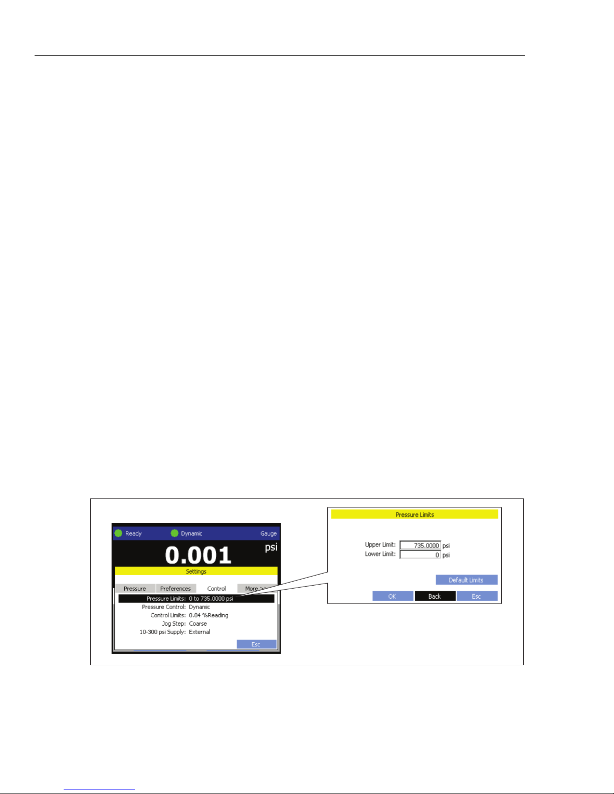
4322
Operators Manual
Set the Pressure Limits and Control Limits
Pressure Limits (Upper and Lower)
Pressure control limits are user configurable settings the Controller uses to make sure that
applied pressure does not exceed the operator defined limitations. Control parameters are
configured in the settings menu and also in the test menu.
Note
Control parameters are set in the settings and also in the Test Sequence
parameters. When a test is run, the Controller reads the settings in the test
file and temporarily changes the settings to the settings contained in the
test. After the test is complete, the Controller automatically reverts back to
the settings that were set before.
See the subsequent sections for more information on each control limit.
The upper and lower pressure limits are user configurable pressure limits that protect the
UUT from accidental overpressure. The limits are used when the target pressure is
manually set from the Main menu. If the target pressure keyed in is more than the upper
limit or less than the lower limit, the Controller will not accept the target pressure value
and displays an out of range error message.
Note
When a Test Sequence is run, the Controller automatically vents excess
pressure to protect the UUT if pressure greater than 110 % of the UUT full
scale range is sensed. No manual setting of upper limit or other settings is
necessary to engage this protection.
Change the Upper and Lower Pressure Limits as follows (3-9):
1. Select on the Main menu.
2. Select the
3. Select
4. Set the
Control tab.
Pressure Limits to open the pressure limits menu.
Upper and Lower Pressure Limits for the UUT.
5. Select to save and close the menu.
Figure 3-9. Pressure Limits
gxj056.eps
3-12
Page 67
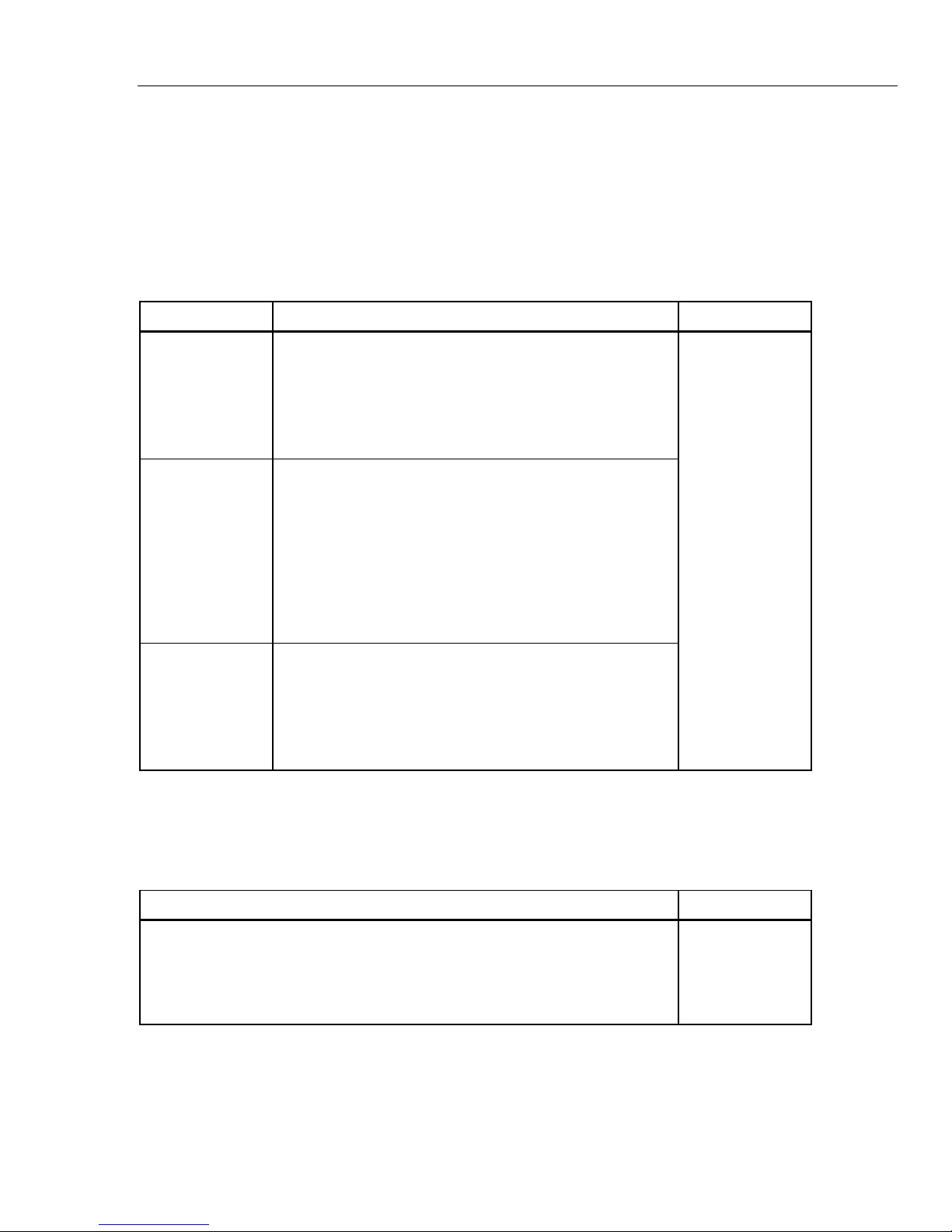
Controller Operation
Set and Control Pressure 3
Control Limits (Hold and Stability)
The control hold limit is a symmetrical positive and negative range of pressure above
(upper limit) and below (lower limit) the target pressure (see Figures 3-5, 3-6, and 3-8).
The Controller does not let the applied pressure go outside the hold-limit range. The hold
limit is used to determine
combination of the hold limit and stability limit to determine
Ready in dynamic control mode. Static control mode uses a
Ready. The hold-limit
ranges are different for each mode (See Table 3-3).
Table 3-3. Hold limits
Control Mode Value in Settings Value in Test
Dynamic Control
Dynamic Control
Mode with Jog
Approach
Static Control
The stability limit is a rate of pressure change limit used to tell if the pressure has
stabilized enough to make a measurement. If the pressure is within the stability limits, the
Controller changes the Measurement Indicator to
limits.
Default dynamic hold limit value is 0.1 % of target pressure
value. This percentage can be changed in the settings menu.
Example: The upper and lower dynamic hold limit for a target
value of 6,000 psi is 6 psi (6,000 psi x 0.1 % = 6 psi).
The Controller keeps the pressure stable between 5,994 psi
and 6,006 psi.
Default dynamic with approach hold limit value is 0.1 % of
reduced target pressure value. This percentage can be
changed in the settings menu.
Example: The upper and lower dynamic with approach hold
limit for a reduced target value of 6,000 psi is 6 psi (6,000 psi x
0.1 % = 6 psi). The Controller keeps the pressure stable
between 5,994 psi and 6,006 psi. Each time Jog Step is
pushed, the pressure increases and the hold limit increases
with it (see Figure 3-7).
Default static hold limit value is 1 % of target pressure value.
This percentage can be changed in the settings menu.
Example: The upper and lower static hold limit for a target
value of 6,000 psi is 60 psi. (6,000 psi x 1 % = 60 psi). The
Controller keeps the pressure stable between 5,940 psi and
6,060 psi.
Ready. See Table 3-4 for the stability
Table 3-4. Stability Limits
Current value in
settings or 10 % of
the UUT tolerance
value, whichever is
greater.
The default Stability Limit value is 0.1 % of target pressure value change per second.
This percentage can be changed in the settings menu.
Example: The Stability Limit for a target value of 6,000 psi is 6 psi/second (6,000 psi
x 0.1 % = 6 psi).
Value in Settings Value in Test
Current value in
settings or 10 % of
the UUT tolerance
value, whichever is
greater.
3-13
Page 68
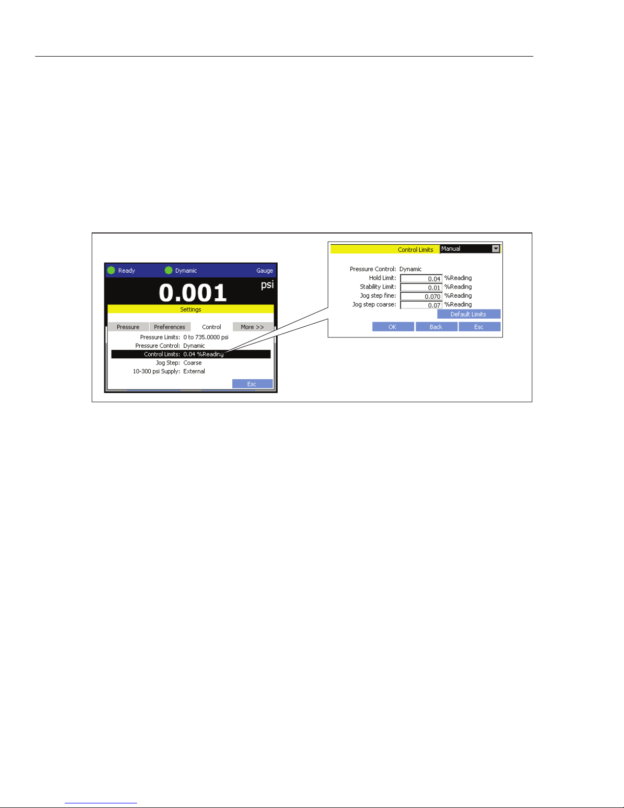
4322
Operators Manual
Change the Control Limits as follows (see Figure 3-10):
1. From the Main menu, select to open the settings menu.
2. Select the
3. Select
4. Set the
Control tab.
Control Limits to open the control limits menu.
Hold Limit. The hold limit is a pressure range above and below the target
pressure. The Controller keeps the pressure within the range when in dynamic mode.
5. Set the
Stability Limit. The stability limit is a stability setting that is set to determine
if the pressure is stable enough to make a measurement.
6. Select to save and close the menu.
Figure 3-10. Control Limits
gxj055.eps
Pressure Control Functions
Read the subsequent sections for instructions on how to use the three pressure control
functions: jog, vent, and abort.
Jog Step Pressure Up or Down
Jog Step is a pressure control function that increases or decreases pressure incrementally.
The Jog Step can be set to be a Fine step or Coarse step (see Table 3-5 for fine and coarse
parameters).
To Jog Step pressure, push and on the control panel when pressure control is
active. Push to change between Fine and Coarse.
3-14
Page 69
Controller Operation
Set and Control Pressure 3
Table 3-5. Jog Step Parameters
Control Mode Value in Settings Value in Test
Fine Jog Step
Coarse Jog Step
Change Between Coarse and Fine as follows:
Push on the Control Panel or the Handheld Controller when pressure is dynamically
controlled.
-- or --
From the Main menu:
1. Select the
2. Select
Change the Jog Step Parameters:
1. From the Main menu, select to open the settings menu.
The default Fine Jog Step value is 0.05 % of target pressure
value. This percentage can be changed in the settings menu.
Example: A Fine Jog Step for a target value of 6,000 psi is 3 psi
(6,000 psi x 0.05 % = 3 psi).
Each time Fine Jog Step is pushed, the pressure increases or
decreases 3 psi.
The default Jog Step value is set to 1 % of target pressure value.
This percentage can be changed in the settings menu.
Example: A Coarse Jog Step for a target value of 6,000 psi is
60 psi. (6,000 psi x 1 % = 60 psi). Each time Course Jog Step is
pushed, the pressure increases or decreases 60 psi.
Jog Step Indicator.
Coarse or Fine.
Current value in
settings or 5 % of
the UUT tolerance
value, whichever is
greater.
Current value in
settings or 1 % of
the UUT tolerance
value, whichever is
greater.
2. Select the
3. Select
4. Set the
5. Set the
Control tab.
Control Limits to open the control limits menu.
Jog Step Fine.
Jog Step Coarse.
6. Select to save and close the menu.
Vent the Controller
The key on the control panel completely vents applied pressure at a controlled rate
when pushed. If is pushed when a test is in progress, the test immediately stops and
Controller vents all pressure in the system.
Abort for Emergency Pressure Relief
For emergency pressure relief, the red key immediately vents all pressure and cancels
the test. When the red key is pushed, the Controller closes any open menus and
returns to the Main menu.
The Controller has an automatic pressure relief function that releases pressure if it
exceeds the upper or lower pressure limits. If an over pressure occurs, the Controller
sounds an alarm for 8 seconds, aborts the test, and logs an event in the Event Log (see
“Event Log” in Chapter 4). In addition, if the display is rotated to access the Pressure
Transducer Modules and pressure control is active, the Controller performs an automatic
emergency pressure relief to protect the user.
To recover from an over pressure, correct the over pressure condition and then cycle
Controller power.
3-15
Page 70
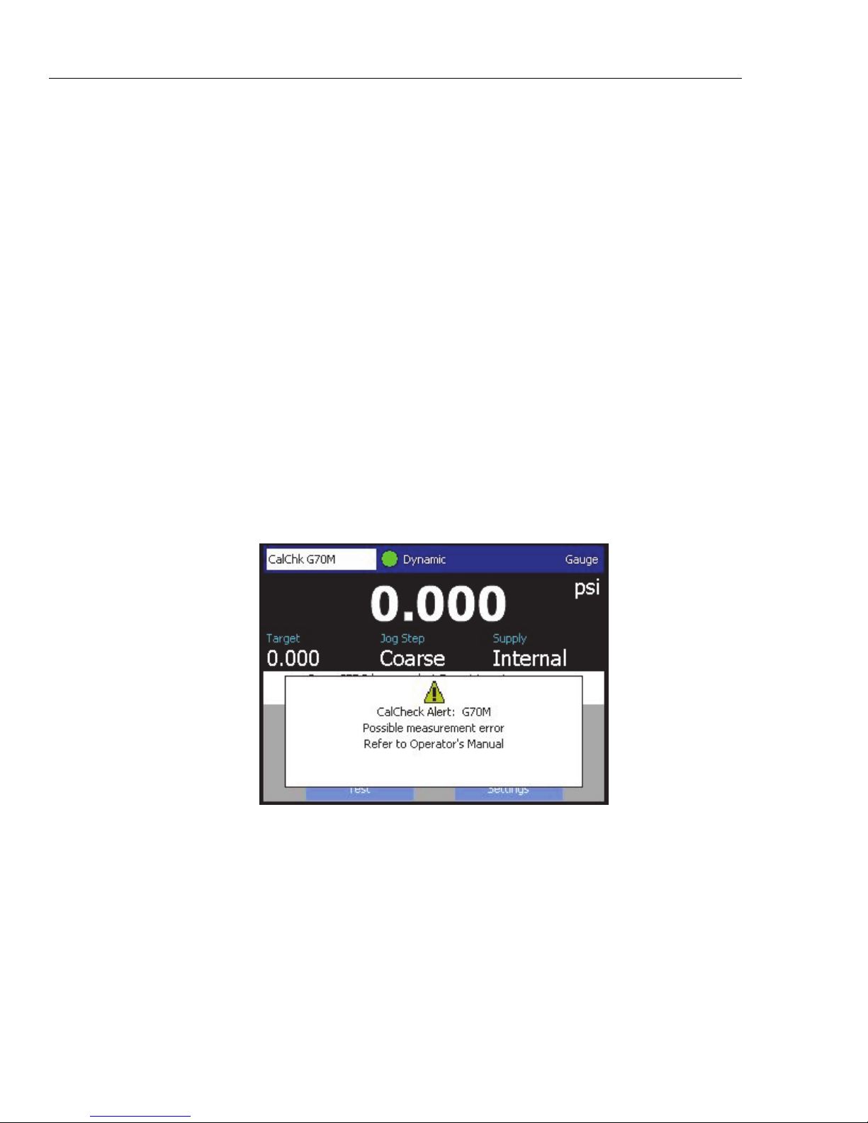
4322
Operators Manual
Measurement Settings and Limits
CalCheck Function
Note
When a Test Sequence is run, the Controller automatically vents excess
pressure to protect the UUT whenever pressure greater than 110 % of the
UUT full scale range is sensed. No manual setting of upper limit or other
settings is necessary to engage this protection.
The Controller relies on multiple sensors to not only improve measurement performance,
but also to detect potential failure or out of tolerance conditions before erroneous
measurements are performed.
Each pressure module features three redundant pressure sensing elements. Measurement
uncertainty is reduced during normal operation by averaging the output of the three
elements to determine the final pressure measurement used by the Controller. The
Controller also monitors the individual pressure measurement of the elements and
compares them to each other. If one of the elements does not agree with the other two
within expected limits, the Controller will display an on-screen CalCheck alert. In
addition to the alert, a “CalChk” notification indicating the range of the suspect pressure
module will appear in the upper left portion of the Main menu over the Ready Indicator
until the issue is resolved (the indicator flashes on and off every 2 seconds). The CalChk
indicator can be selected to view the original on-screen error message (see Figure 3-11).
The CalCheck feature is performed constantly and transparently to the operator. Action is
only required if the CalChk indicator is displayed.
gxj061.jpg
AutoZero and BaroCheck
During normal use, the barometer module reads atmospheric pressure through the ATM
port on the front panel of the Controller, and is not exposed to the pressure excursions
seen by the pressure modules. This limited use and the intrinsic measurement
characteristics of the barometer module offer a very stable reference pressure for
measurement assurance features. A direct reading of atmospheric pressure also allows the
Controller to determine gauge pressure with the intrinsically absolute pressure module
and to measure absolute pressure with the gauge pressure modules.
The AutoZero feature compares the active pressure module output to the internal
atmospheric pressure reference, tares the difference and in some modes dynamically
compensates for changes in atmospheric pressure. The function happens automatically
3-16
Figure 3-11. CalCheck Indicator
Page 71

Controller Operation
Measurement Settings and Limits 3
and seamlessly during every vent operation after the Controller has determined that
pressure measurement is fully vented and stable.
• Gauge pressure measurement with intrinsically gauge pressure modules (G700K,
G10M, G70M): AutoZero tares the reading to zero gauge pressure at vent.
• Absolute pressure measurement with intrinsically gauge pressure modules (G700K,
G10M, G70M): AutoZero tares the reading to zero gauge pressure measurement at
vent. For all subsequent measurements, the output is dynamically compensated to
indicate absolute pressure by adding the outputs of the active gauge pressure module
and the barometer module.
• Gauge and vacuum pressure measurement with the intrinsically absolute pressure
module (A150K): AutoZero tares the reading to zero gauge pressure at vent. At all
other pressures, the output is dynamically compensated for small changes in
atmospheric pressure measured by the barometer module.
• Absolute pressure measurement with the intrinsically absolute pressure module
(A150K): AutoZero tares the reading to zero gauge pressure measurement at vent.
For all subsequent measurements, the output is dynamically compensated to indicate
absolute pressure by adding the outputs of the active gauge pressure module and the
barometer module.
The BaroCheck feature also utilizes the stability of the barometer module to ensure
measurement performance at low pressure. The BaroCheck function compares the
outputs of the A150K pressure module and the barometer module at several points in the
atmospheric pressure range. If the pressure modules agree within the expected tolerance,
the BaroCheck function will compensate the output of the A150K pressure module by the
difference. If the pressure modules do not agree within the expected tolerance, one of the
components may be failing or exceeding measurement tolerance, so compensation will
not be applied and the Controller will alert the user to a potential measurement issue.
The BaroCheck function is recommended to be run at least once every 30 days. The
Controller keeps track of when BaroCheck has been run, and will indicate if 30 days has
been exceeded with a “BaroChk” indication in the top left of the Main menu.
The BaroCheck function can be performed by selecting “BaroCheck” under the
Calibration tab in the Settings Menu while in Advanced Mode. If the user selects to run a
test procedure or perform a calibration while the Controller is displaying the BaroCheck
indication, the operator will be prompted to first perform the BaroCheck routine. If more
than 45 days has passed since the last successful BaroCheck routine, the Controller will
force BaroCheck to be performed before proceeding with a test procedure or calibration.
BaroCheck is performed automatically once initiated. When running the BaroCheck
function, the Controller will prompt the operator to cap the test port and acknowledge to
proceed. The controller will indicate that BaroCheck is in progress for approximately 5 to
10 minutes as it automatically sets several test points and verifies measurement. The
Controller will beep three times at the conclusion of the test to alert the user that the
function is complete. If BaroCheck detects damage or a suspected an out of tolerance
condition, the Controller will notify the user to perform the BaroCheck function again or
to check calibration of the A150K and barometer modules.
3-17
Page 72
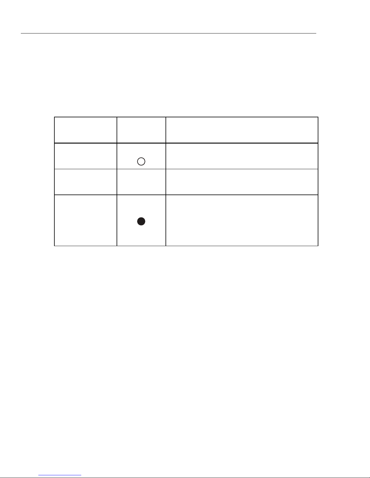
4322
Operators Manual
Measurement Indicator
The Measurement indicator (also known as the “Ready indicator” in previous products) is
a visual indicator that shows when the pressure is stable enough to make an accurate
measurement. See Table 3-6 for a list of Measurement Indicators and their definition. For
the indicator to change to
Ready, the rate of pressure change has to be within the stability
limits and the pressure needs to be inside the hold-limit range for the active pressure
control mode. See “Pressure Limits (Upper and Lower)” on page 3-12.
Table 3-6. Pressure Status Indicator
Handheld
Indication
Control
Indication
Definition
(Red) Not Ready
(Yellow) Near Ready
(Green) Ready
Here is an example that shows what indications will show at the different states of
pressure control:
1. A target pressure is set, either on the Main menu or as a test point in a Test Sequence.
2. The Controller reads the target pressure and precisely controls two high-pressure
valves to supply pressure to the UUT. When pressure is ramping towards the target,
the measurement indicator shows
3. As the pressure builds, the Controller measures the applied pressure and reports the
rate of pressure change. As the applied pressure approaches the hold limit, the
Controller decreases the rate of pressure change to prevent a target pressure
overshoot. When the pressure starts to stabilize near the target pressure, the
measurement indicator changes to
4. The Controller continues to decrease the rate of pressure change as the applied
pressure gets closer to the target pressure. If the pressure is within the hold limits, the
measurement indicator changes to
NR
No Indication
R
Indicates that there is currently a high rate of pressure
change and the pressure is not stable enough to make a
measurement.
Indicates that there is currently a medium rate of pressure
change and the pressure is almost stable enough to make a
measurement.
Indicates that the pressure is stable and the rate of pressure
change is within the stability limits. A measurement can be
made.
Note
Ready shows when the Controller is vented to indicate that
it is OK to make an ATM or 0 psig measurement.
Not Ready.
Near Ready.
Ready and a measurement can be made.
Measurement Modes
The Measurement Mode is a user configurable setting that sets the Measurement Mode.
The three Measurement Modes are Absolute, Gauge, and Vacuum.
•
Absolute mode adds barometric pressure to the measured gauge pressure to get an
equivalent absolute pressure. Absolute can never be shown as a negative value.
•
Gauge mode uses pressure modules to measure positive pressure (relative to
atmosphere).
•
Vacuum mode uses pressure modules to measure negative gauge pressure (relative
to atmosphere).
3-18
Page 73
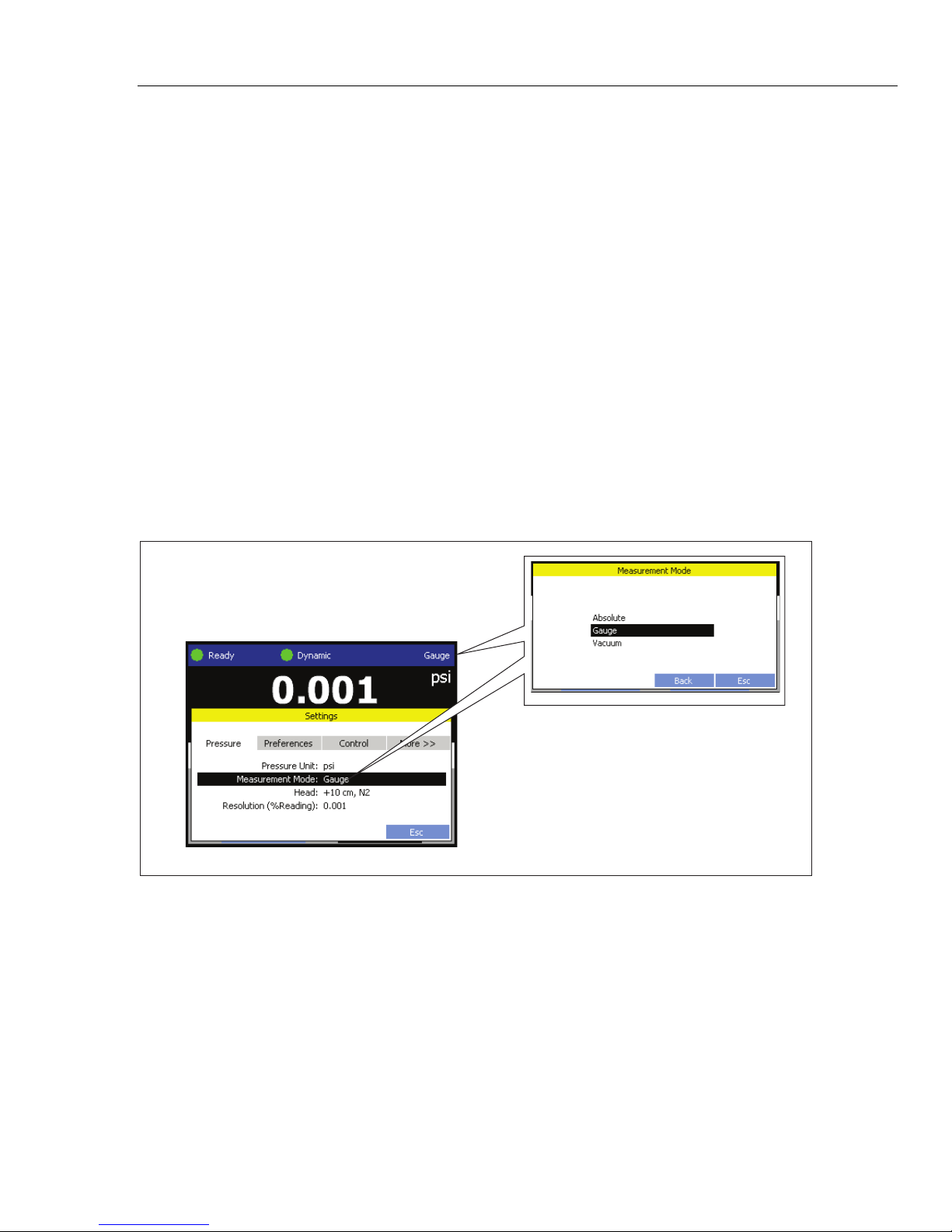
Controller Operation
Measurement Settings and Limits 3
Note
The Controller displays vacuum pressures as negative values (for
example, -9.32 psig). Some vacuum gauges do not show a negative
sign (-) in front of the reading because they are used for only vacuum
measurements (the vacuum gauge would show “9.32 psi vacuum”
without the negative sign). To prevent misinterpretation of the vacuum
gauge reading compared to the negative value on the Controller, look
at the gauge face or user documentation to see how the vacuum gauge
shows vacuum pressures.
Change the Measurement Mode as follows (see Figure 3-12):
1. Select the
2. Select
Measurement Mode Indicator on the Main menu.
Gauge, Absolute, or Vacuum.
--or--
1. Select on the Main menu.
2. Select the
3. Select
4. Select
Pressure tab.
Measurement Mode to open the control mode settings.
Gauge, Absolute, or Vacuum.
Measurement Resolution
The Controller displays the measured pressure value. The Measurement Resolution
selections are 1.0, 0.1, 0.01, or 0.001 % of reading. The statement “% of reading” means
that the Controller multiplies the measured value by the resolution to determine how
many digits to show. For example, if the actual measured value was 7,000.1234 psi and
the resolution was set to 0.001, the Controller shows 7,000.1. The resolution limited to
1 % of measurement uncertainty across the entire range, with an ultimate minimum
setting of 2.5 Pa (0.00004 psi).
Figure 3-12. Measurement Mode Settings
gxj047.eps
3-19
Page 74
4322
Operators Manual
Change the Measurement Resolution as follows (see Figure 3-12):
1. Select the
2. Select
Measurement Indicator from the Main menu.
1.0, 0.1, 0.01, or 0.001.
--or--
1. Select on the Main menu.
2. Select the
3. Select
4. Select
Pressure tab.
Resolution (%Reading) to open the resolution settings.
1.0, 0.1, 0.01, or 0.001.
Unit of Measure
The Controller has a large selection of standard engineering units that can be selected to
satisfy a large majority of calibration requirements. Sometimes, special calibrations
require an uncommon or special unit of measure. These nonstandard units are referred to
as user defined units. The Controller lets the user define up to five units to use and save
for future use. Table 3-7 is a list of the selectable standard units and their descriptions.
Table 3-7. Units of Measure
Unit Description Unit Description
MPa Mega Pascal gfcm Grams force per square centimeter
Pa Pascal inHg32F Inches of mercury at 32 °F
mbar Millibar inHg60F Inches of mercury at 60 °F
kPa Kilo Pascal kgm2 Kilogram force per square meter
bar Bar kgmm2 Kilogram force per square millimeter
mmHg0C Millimeters of mercury at 0 °C cmH2O4C Centimeters of water at 4 °C
Torr Torr (also mmHg) cmH2O20C Centimeters of water at 20 °C
mTorr MilliTorr mmH2O20C Millimeters of water at 20 °C
psi Pounds per square inch inH2O4C Inches of water at 4 °C
osi Ounces per square inch inH2O20C Inches of water at 20 °C
psf Pounds per square foot inH2O25C Inches of water at 25 °C
inHg0C Inches of Mercury at 0 °C inH2O60F Inches of water at 60 °F
kgcm2 Kilograms per square centimeter ftH2O20C Feet of water at 20 °C
ATM Atmospheres mmSW20C Millimeters of salt water 20 °C
cmHg0C Centimeters of mercury cmSW20C Centimeters of salt water at 20 °C
dyncm Dynes per square centimeter inSW20C Inches of salt water at 20 °C
ftHg0C Feet of mercury ftSW20C Feet of salt water at 20 °C
kpin Kips per square inch mHg0C meters of mercury at 0 °C
hPa Hecto Pascal
3-20
Page 75
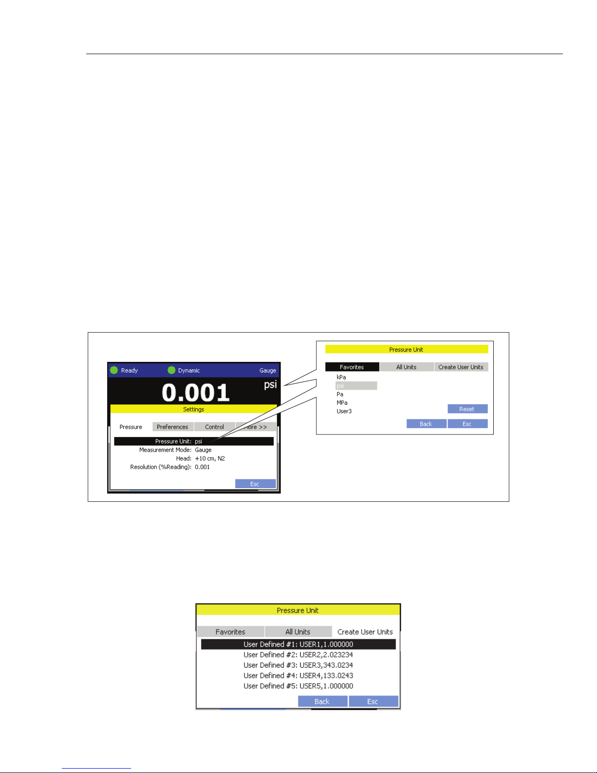
Controller Operation
Measurement Settings and Limits 3
Change the Unit of Measure as follows (see Figure 3-13):
Note
If the Controller does not have a unit that the calibration requires, a custom
measurement unit can be made. The custom unit is referred to as a “User
Unit”. To make a User Unit, select the Create User Unit tab on the units
menu and select a user defined unit. A menu will open that has settings to
define a unit. The user unit is a number in relation to 1 Pa.
1. Select
2. Select a
Unit of Measure indicator on the Main menu to open the supply menu.
Unit of Measure from the list. Commonly used units are in the Favorites tab
and all units are in the
All Units tab. User Units are also listed in the All Units tab.
--or--
1. From the Main menu, select to open the settings menu.
2. Select the
3. Select
4. Select a
and all units are in the
Pressure tab.
Pressure Unit.
Unit of Measure from the list. Commonly used units are in the Favorites tab
All Units tab. User Units are also listed in the All Units tab.
Make a Custom User Unit:
1. Open the Pressure Unit menu (see “Unit of Measure” in the previous procedure).
2. Select the
3. Select a
4. Enter the
Create User Units tab.
User Defined # to edit.
Unit Name.
Figure 3-13. Unit of Measure
gxj048.eps
3-21
Page 76
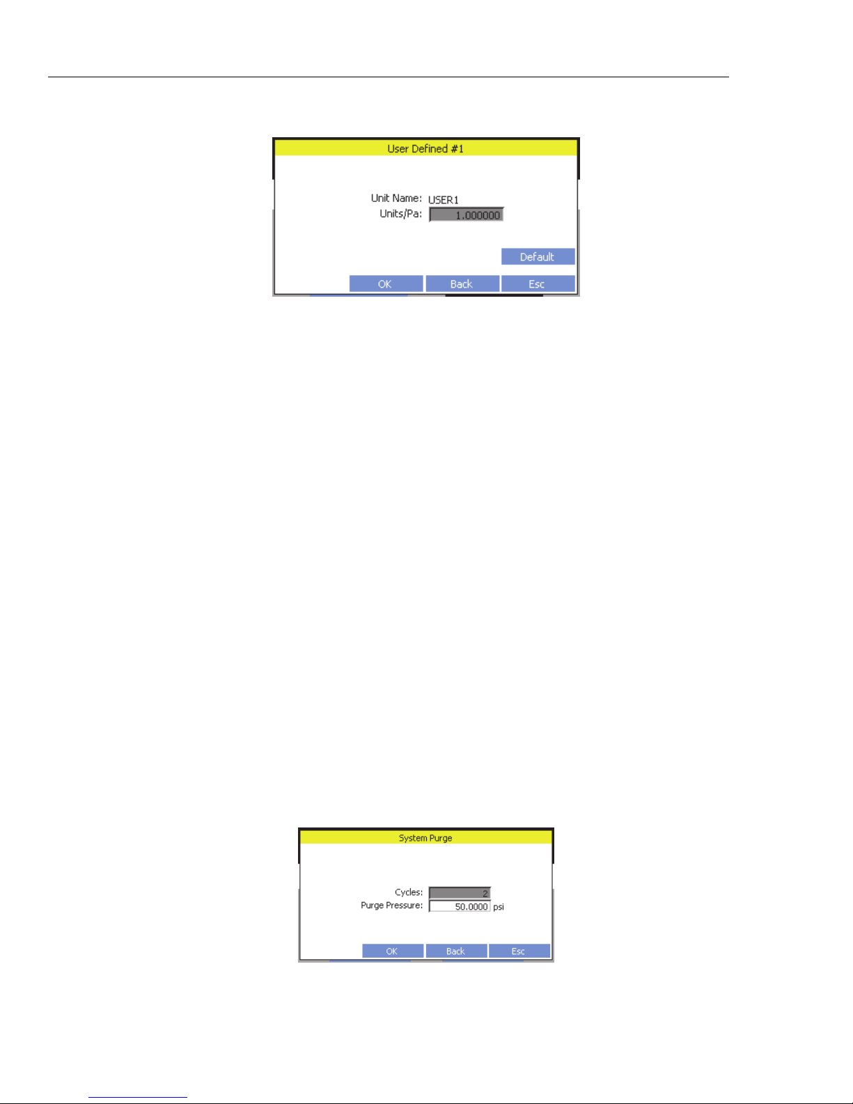
4322
Operators Manual
UUT Tolerance Limit
Controller Tools
5. Enter the Units/Pa.
The UUT tolerance limit is the maximum anticipated deviation between the reading of
the UUT and the measurement made by the Calibrator. After a test is complete, the
Controller compares the UUT Tolerance limit against the actual test results. From the
comparison, the Calibration report shows if a UUT passed or failed. UUT Tolerance limit
is a mandatory test parameter when a test is setup.
The Controller includes a set of standard functions (tools) typically performed prior to
calibration including a system purge, a hose purge, a leak test, and exercise a UUT. Read
the subsequent sections for more information on each tool.
System Purge
System Purge is a function of the Controller that pressurizes and vents the test system
plumbing connected to the Controller. It is recommended to do a system purge before a
calibration is performed to rid the system of contaminates when you expect that liquid or
particulate contaminates are present. The Controller is designed to maintain internal
cleanliness during any operation, but contaminates are most easily handled during a
relatively low pressure purge. To purge the system, the Controller pressurizes to the userdefined purge pressure then immediately vents to the plastic waste container. The process
will repeat for as many cycles that are set.
Purge the system as follows:
1. Connect the male end of the test hose to the female
2. Connect female end of the test hose to the male
hose is not used, connect the male QC adaptor fitting of the UUT directly to the
TEST port.
3. Navigate to and select
menu opens.
TEST port on the Controller.
QC adapter on the UUT. If a test
System Purge on the bottom of the Main menu. A purge
4. Key the number of times to cycle into the Cycles field.
5. Key in the amount of pressure into the
3-22
Purge Pressure field.
Page 77
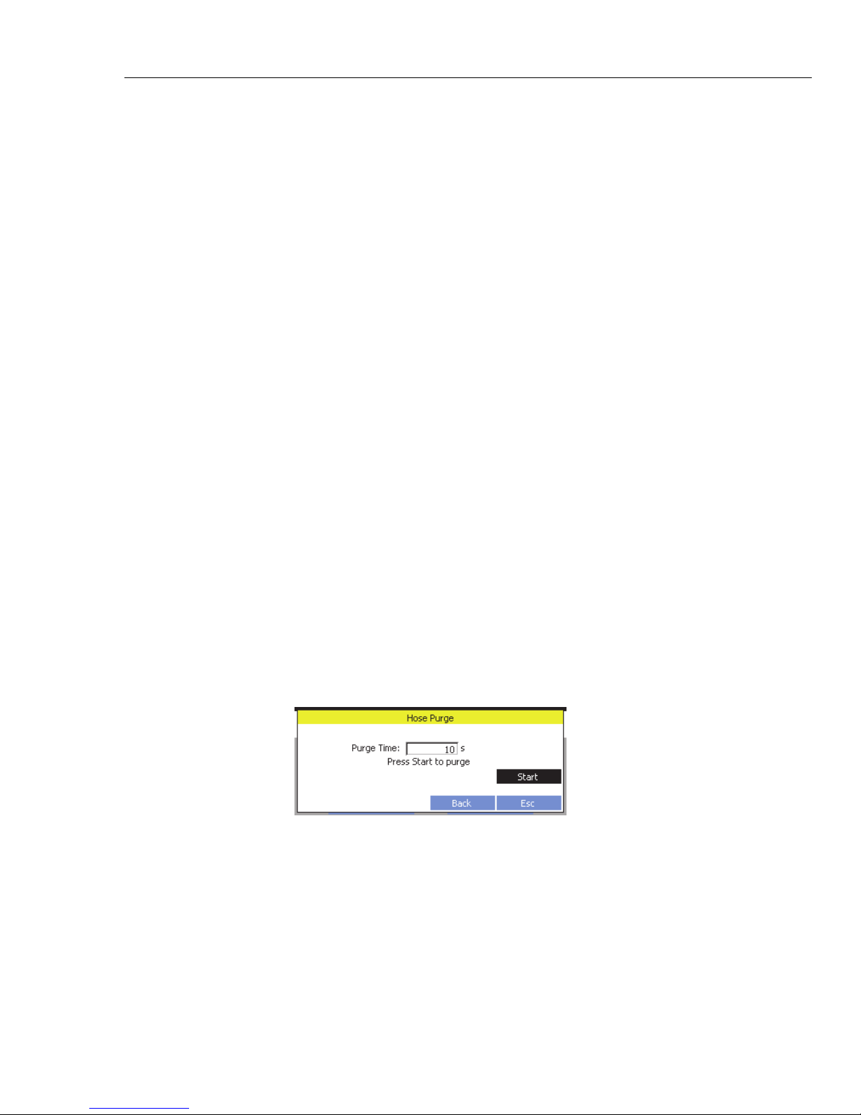
Controller Operation
Controller Tools 3
6. Select OK. The Controller will automatically perform the number of system purge
cycles specified.
Note
A System Purge draws contaminants out of the UUT. During this process,
some of the contaminant can remain in the test hose. It is recommended to
perform an additional Hose Purge after System Purge if such
contamination is suspected.
Hose Purge
Hose Purge is a function of the Controller that cleans test hoses before they are connected
to a UUT. When pressure is vented after a test, liquids, oils, gases, or solvents from the
UUT can adhere to the test hose and the coalescing filters. To help clear the contaminates
from the test hose, the Controller has a hose purge function that forces the fluids out of
the hose and into the CPS waste container.
Some contaminates are difficult to remove with air pressure alone and trace amounts can
possibly stay in the test hose and CPS after the purge is complete. If contaminants remain
after the purge, remove the hose, flush it with a solvent and then reattach and run the
Hose Purge again.
When the Hose Purge starts, the Controller continuously flows gas for the length of the
test (purge time) then vents to atmosphere.
Caution
To prevent UUT cross-contamination, always use a like-colored
test hose and CPS.
Purge a test hose as follows:
1. Connect the male end of the test hose to the female
TEST port on the Controller (see
Figure 3-14).
2. Connect female end of the test hose to the male
HOSE PURGE port on the Controller
(see Figure 3-14).
3. Navigate to and select
Purge on the bottom of the Main menu. The Purge menu
opens.
4. Key the purge time in seconds into the Purge Time field.
5. When ready, navigate to and select to start the test hose purge. When the
purge is complete, the Controller beeps three times.
6. Disconnect the test hose from the
HOSE PURGE port and put the protective cap on.
3-23
Page 78
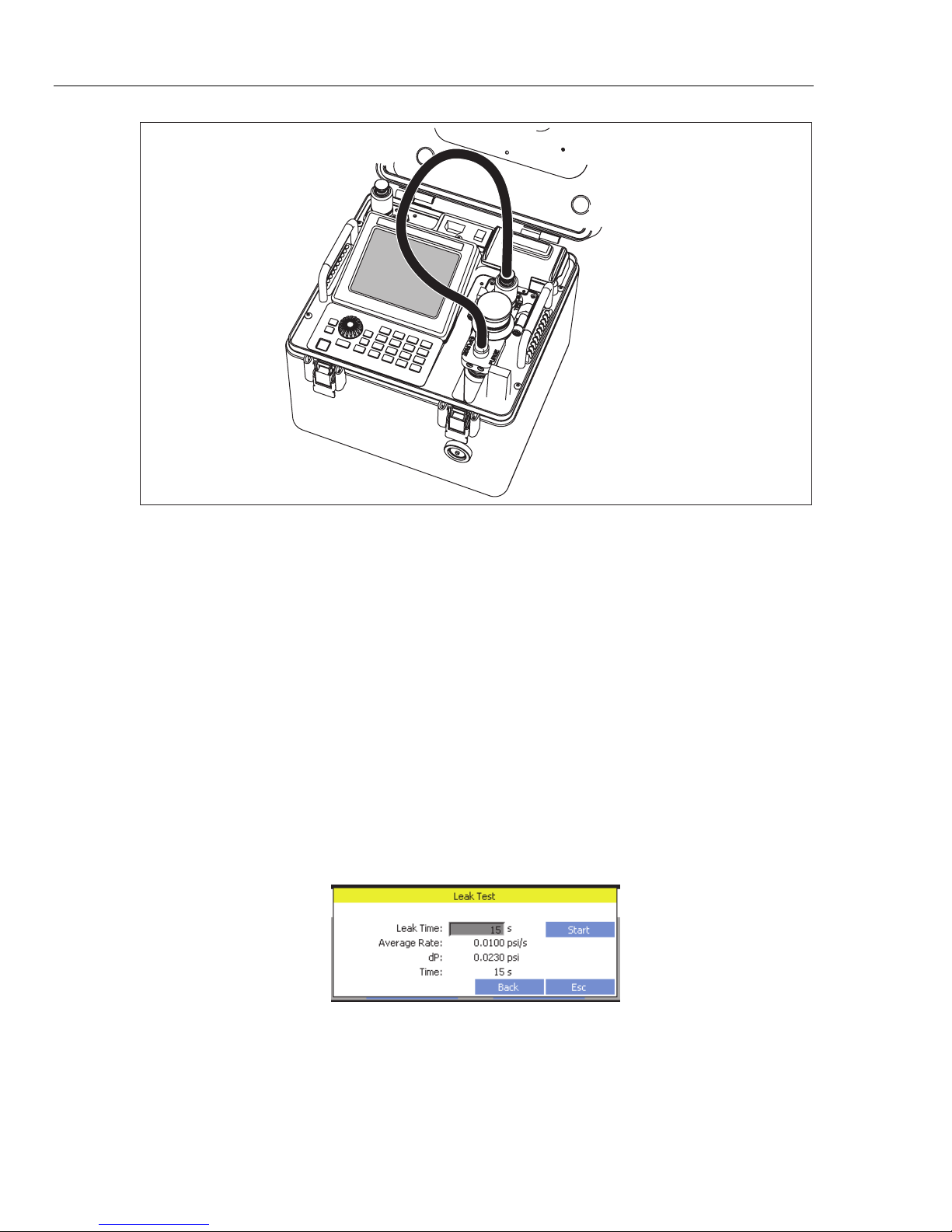
4322
Operators Manual
Figure 3-14. Hose Purge Configuration
gxj028.eps
Leak Test
Leak Test is a function of the Controller that checks the Controller and UUT connection
for pressure leaks. To detect leaks, the Controller generates pressure and monitors the
rate of pressure change over a time period. The total change in pressure (dP) and average
rate of change is shown on the Leak Test menu and stays on the menu until the test is
reaccomplished. See Table 3-8 for a list of leak test parameters.
Test the system for leaks as follows:
1. Connect the male end of the test hose to the female TEST port on the Controller.
2. Connect female end of the test hose to the male
3. Navigate to and select on the bottom of the Main menu. The Leak Test
4. Key the leak test time in seconds into the Leak Time field.
QC adapter on the UUT.
Note
A leak test can be done without a UUT connected to troubleshoot the
Controller.
menu opens.
The leak test menu contains an Average Rate, dP (pressure change),
and Time values. These values are leak test result values and are not
adjustable settings. When the menu opens, the values shown are from
the last test completed and will update after the leak test is complete.
3-24
Note
Page 79
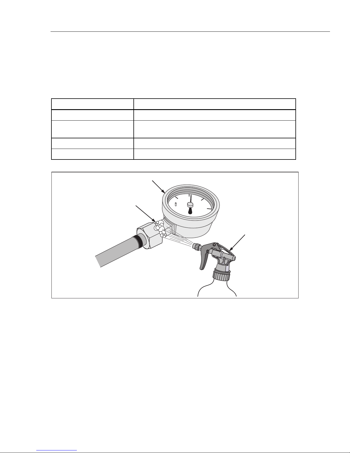
Controller Operation
Controller Tools 3
5. Navigate to and select to start the leak test.
6. If the leak rates are excessive, search for a leak path around the adapter fittings first.
To search for leaks, use a spray bottle with a mixture of water and diluted soap to
spray on the fittings. If a there is a leak, bubbles from the soap visually show where
the leak is. See Figure 3-15.
Table 3-8. Leak Test Parameters
Parameter Description
Leak Time Amount of time to run the leak test.
Average Rate Shows the average rate of change of pressure for the test completed.
Measured in units for each second.
dP Shows the total change in pressure for the test completed.
Time Shows the length of time the test ran.
UUT
Exercise
Exercise is a function of the Controller that pressurizes the UUT to a Max Target
pressure then vents or otherwise sets pressure to the Min Target pressure. This sequence
is repeated for the number of cycles set in the Exercise menu.
When the exercise starts, the Controller pressurizes the UUT to the Max Target pressure
then depressurizes to the Min Target pressure. If Control at Target is set to “Yes”, the
Controller uses the active pressure control mode to control the pressure for amount of
time set in the Delay at Target. This is repeated for the number of cycles set.
Bubbles Show a Leak
200
100
Figure 3-15. Visual Leak Detection
300
400
50
Spray Bottle
gxj045.eps
Exercise a UUT as follows:
1. Connect the male end of the test hose to the female
2. Connect female end of the test hose to the male
3. Turn-on the Controller (if necessary).
TEST port on the Controller.
QC adapter on the UUT.
3-25
Page 80
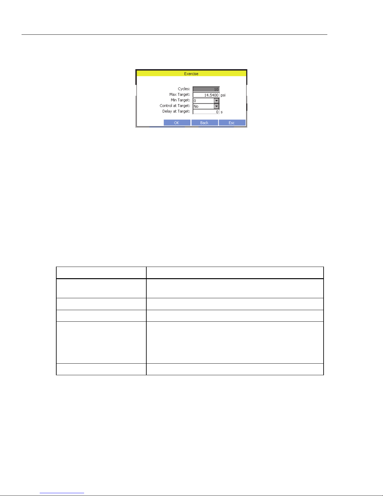
4322
Operators Manual
4. Navigate to and select on the bottom of the Main menu. An Exercise
menu appears.
5. Configure the test as follows:
a. Set the number of times to exercise the UUT in the
b. Set the maximum target pressure in the
c. Set the minimum target pressure in the
d. Set the pressure control to
Yes or No in the Control at Target field.
Max Target field.
Min Target field.
Cycles field.
Note
If “Yes” is selected for Control at Target, the Controller uses the active
control mode set in the Controllers settings. Refer to “Pressure Control
Modes” on page 3-8.
e. If Control at Target is set to “Yes”, set the time in seconds to keep the pressure at
the target pressures in the
Delay at Target field.
6. Select to save and close the menu to start the test.
Table 3-9. Exercise Test Parameters
Parameter Description
Cycles Set the cycles. A single cycle is one pressurization to the maximum
target pressure and back to the minimum target pressure.
Max Target Maximum target pressure.
Min Target Minimum target pressure.
Control at Target Set whether to control pressure at the target value. If Yes, then the
Delay at Target Amount of time to control pressure if Control at Target is set to “Yes”.
Test a UUT
Use the instructions in the subsequent sections to set up and run a test on a UUT.
3-26
test uses the active pressure control mode (see “Pressure Control
Modes”). If no, then the Controller controls pressure to the maximum
target value then immediately controls pressure to the minimum
target value.
Page 81
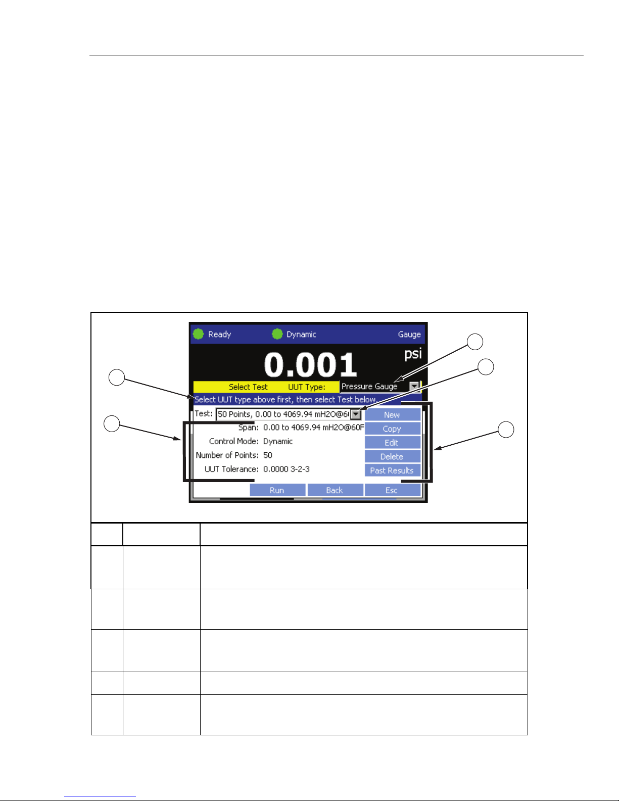
Controller Operation
Test a UUT 3
The Test Menu
The Test menu allows for quick access to run a test, edit a test, or make a new test (see
Table 3-10). Each UUT type selection has different test options and settings that show on
the menu. Once a UUT type is selected, the test drop-down menu shows a list of all saved
tests for the UUT type and shows the related test options and settings on the test menu. If
a test cannot be located in the list with the necessary test parameters, a new test can be
made.
Note
The New Test menu contains a “Matching Test” field. This field compares
the test being made to the tests saved to memory. If a test is found that
matches the parameters of the test being made, the matching test shows in
the Matching Test field. This helps prevent the creation of multiple tests
with the same settings.
See “Test Sequences” on page 3-26 for information on how to manage and use test files.
See “Run a Test Sequence” on page 3-33 for instructions on how to run a Test Sequence.
Table 3-10. Test Menu
5
4
Item Name Function
Shows the selected UUT type and opens a menu to change the UUT type. The
UUT Type
Test
Test
Management
Buttons
UUT types are: Pressure Gauge, Compound Gage, Pressure Switch, and
Transducer.
Test selection list. List is populated with saved tests and each UUT type has a
different list. Each test has a naming convention to easily see the parameters of
the test in the test name (see “About Test Sequences” on page 3-28).
Buttons used to make, edit, and manage tests. See “Test Sequence Actions” on
page 3-28 for test file management instructions.
1
2
3
gxj014.eps
Test Settings Shows the test settings for the selected test.
On-Screen
Instructions
Shows on-screen instructions and information. The on-screen instructions has
two settings: Standard and Reduced. See the Preferences tab in the “The
Settings Menu” in Chapter 2.
3-27
Page 82
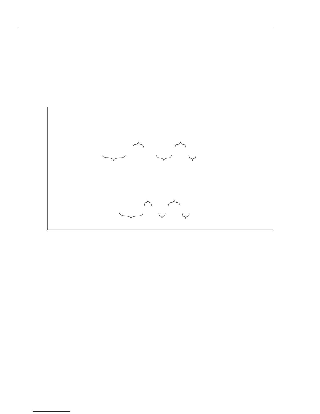
4322
Operators Manual
Test Sequences
A Test Sequence is a test file that is configured by the user and saved to Controller
memory. These test files can be created, edited, saved, and deleted. Each test file contains
test settings and parameters that the Controller uses when the test is run. After the test is
run, the user uses the on-screen prompts to complete the test. After the test is complete,
the user can print or see a test report (see “View Test Results” on page 3-37).
Each test has a specific naming convention so that the main parameters of the test can be
seen in the filename. Once the test is selected, the other parameters of the test are shown
on the test menu. The test naming conventions are illustrated in Figure 3-16.
Test Naming Conventions
Gauge/Transducer Tests:
Convention: [Points], [Minimum Pressure] to [Maximum Pressure] [Unit of Measure] [Measurement Mode]
Example: 8 points, ATM to 40.00 Kpa, g
Minimum
Pressure
Unit of
Measure
8 points, ATM to 40.00 Kpa, g
Number of Test
Points in Test
Switch Tests:
Convention: [“Switch”], [High Up Scale Limit] / [Low Up Scale Limit] [Unit of Measure] [Measurement Mode]
Example: Switch, 84/74 psi, g
High Up
Scale Limit
Maximum
Pressure
Unit of
Measure
Mesurement
Mode
Switch, 84 / 74 Kpa, g
Indicates this is a
Swtich Test
Figure 3-16. Test Name Convention
Test Sequence Actions
Use the Test menu to:
• Create a new test (see “Make a New Gauge or Transducer Test” on page 3-30 or
“Make a New Pressure Switch Test” on page 3-33).
• Copy a saved test (see “Copy a Test” on page 3-29).
• Edit a saved test (see “Edit a Saved Test” on page 3-29).
• Delete a saved test (see “Delete a Saved Test” on page 3-29).
The Controller can save 250 tests to internal memory. Tests are classified by the UUT
type: Pressure Gauge, Compound Gauge, Transducer, and Switch.
Low Up Scale
Limit
Mesurement
Mode
gxj059.eps
The Gauge/Transducer New Test menu looks different and contains
different test settings than the Pressure Switch New Test menu.
As part of the standard factory settings, the Controller comes with a basic set of common
tests for each UUT Type. These tests can be edited to fit the calibration requirements (see
“Edit a Test” on page 3-29).
The Maintenance function “Reset to Defaults” erases all the tests.
3-28
Note
Note
Page 83

Controller Operation
Test a UUT 3
Find a Saved Test
To find and load a saved test:
1. From the Main menu, select to open the test menu.
2. Choose
from the UUT Type drop-down box.
3. Select the
to see the parameters of the test on the test menu.
4. Run the Test Sequence (see “Run a Test Sequence” on page 3-33 for instructions on
how to run the test).
Edit a Test
To edit a saved test:
1. Find the test to edit (see “Find a Saved Test” in this section).
2. Select to open the test Edit menu.
3. Edit the test as necessary. Push cycle through the menus and to save.
4. Run the Test Sequence (see “Run a Test Sequence” on page 3-33 for instructions on
how to run the test).
Copy a Test
To copy a test:
1. Find the test to copy (see “Find a Saved Test” in this section).
Pressure Gauge, Compound Gauge, Pressure Switch, or Transducer
Test drop-down box on the test menu to view the saved tests. Select a test
Note
The tests name contains primary test information to help locate
tests (see Figure 3-16).
2. Select to open the test Edit menu.
3. Edit the test as necessary. Push cycle through the menus and to save.
4. Run the Test Sequence (see “Run a Test sequence” on page 3-33 for instructions on
how to run the test).
Delete a Test
To delete a test:
1. Find the test to delete (see “Find a Saved Test” in this section).
2. Select .
3. Select to confirm deletion.
3-29
Page 84
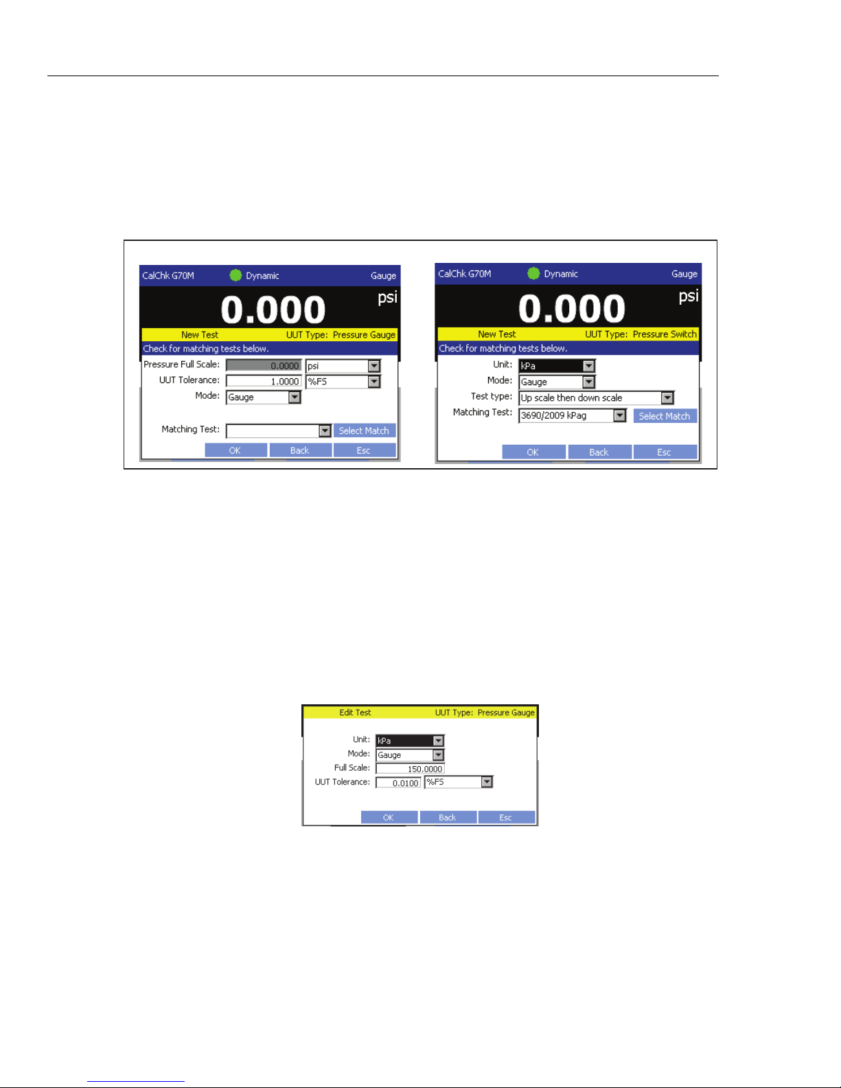
4322
Operators Manual
Make a New Gauge/Transducer Test
Create a new pressure gauge, compound gauge, or transducer test as follows:
Note
The Gauge/Transducer New Test menu looks different and contains
different Test Settings than the Pressure Switch new test menu. Figure 3-17
shows the two menus.
Gauge/Transducer Switch
Figure 3-17. Gauge/Transducer and Switch New Test Menus
1. From the Main menu, select to open the run test menu.
Note
When is selected, the Controller uses the parameters contained
in the test file shown in the Test drop-down box to populate the initial
values of the new test. To make a new test quickly, select a similar test in
the Test drop-down box before is selected.
2. Select
Pressure Gauge, Compound Gauge, or Transducer from the UUT Type
drop-down box.
3. Select on the test menu to open the New Test menu.
4. Configure the test as follows:
gxj041.eps
As a new test is being made and parameters are selected, the Controller
actively searches the saved test files for tests that have the same test
parameters. If the Controller finds a match, the Controller shows the test
matches in the Matching Test field. The Controller searches and updates
the Matching Test Field each time a field is changed. If the Matching Test
Field is selected and then is selected, the new test is not saved
and the Controller opens the test menu with the matching test loaded.
3-30
Note
Page 85
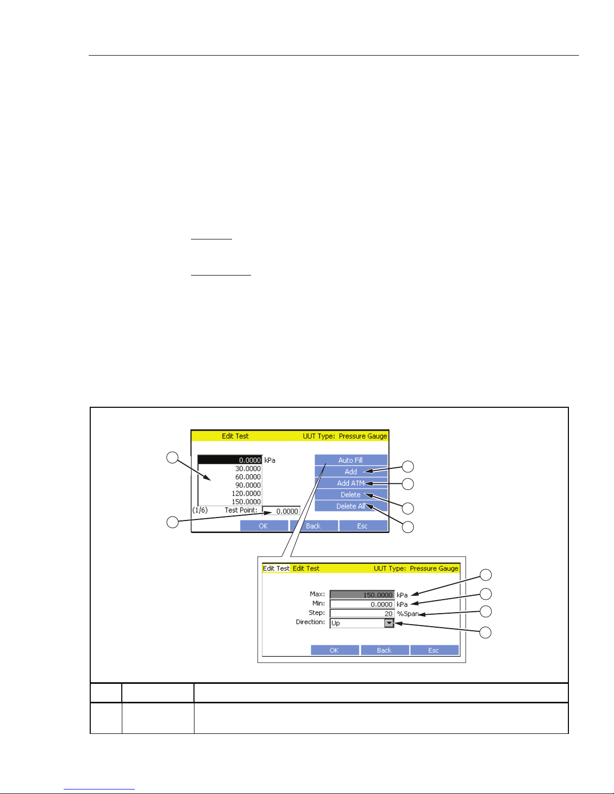
Controller Operation
Test a UUT 3
a. Select a pressure unit from the Unit drop-down box.
b. Select a measurement mode from the
c. Key in the full scale limit of the UUT in the
d. Key in the tolerance of the UUT in the
Mode drop-down box.
Full Scale field.
UUT Tolerance field and select the unit
of scale from the drop-down box.
e. Push to open the edit test menu.
5. Use the Edit Test menu to set up the test points as follows (refer to Table 3-11):
a. Manually change the target values, or use auto fill to automatically set the test
points as follows:
• To manually set the test points, use and . To change the
target value of the test point, select the test point in the sequence window and
key the value into the
Test Point field.
• To automatically make a complete series of test points, select to
open the auto fill menu. Set the maximum target pressure, the minimum target
pressure, the step percentage, and the test direction and select . The
Controller automatically divides the maximum pressure by the step number to
create the number of test points (see Table 3-11 for information on each field).
After the test points are made, they can be manually adjusted on the Edit Test
menu.
b. Add vent to atmosphere (ATM) test points as required. To add an ATM test
point, select a test point in the sequence window and then select . The
point is added below the selected test point.
Table 3-11. Edit Test Menu
Edit Test Menu
2
1
Auto Fill Menu
Item Name/Button Function
3
4
5
6
7
8
9
10
gxj042.eps
Test Point
Target Value
Use to change the target value of the test point.
3-31
Page 86
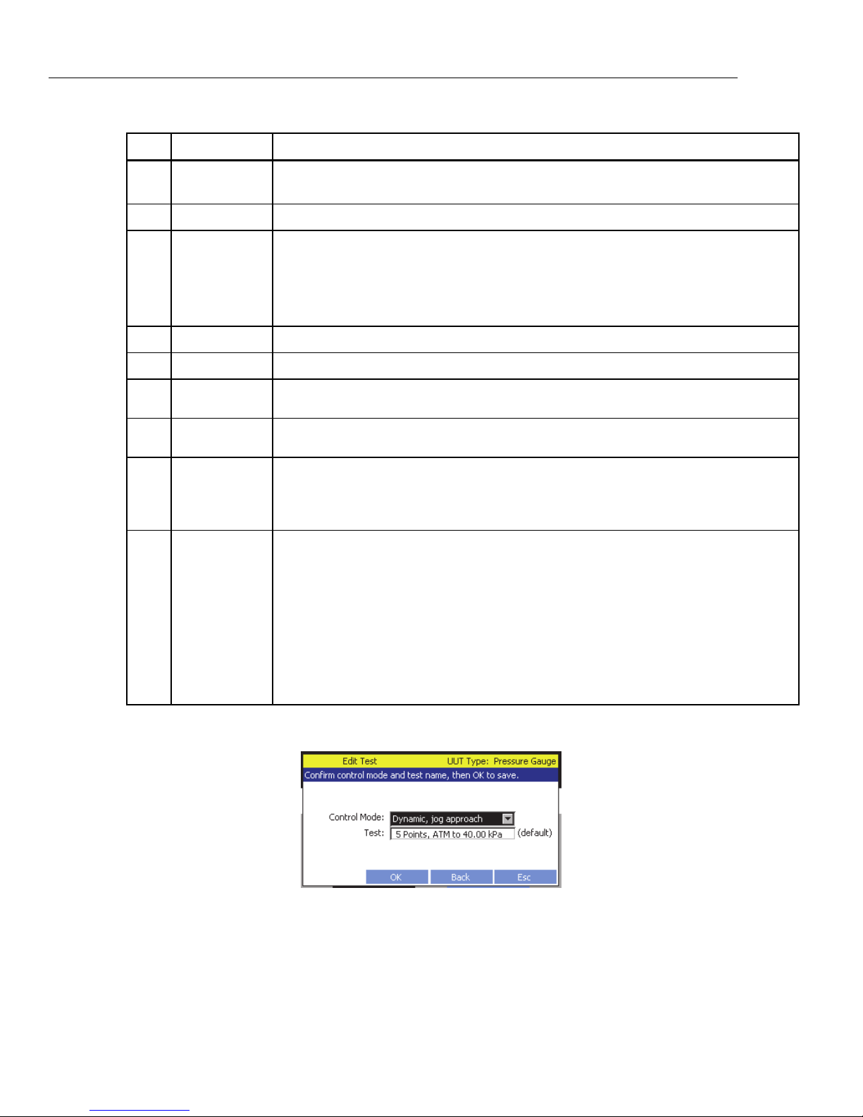
4322
Operators Manual
Item Name/Button Function
Sequence
Window
Table 3-11. Edit Test Menu (cont.)
Shows the number and target value of each test point.
Max
Min
Step
Direction
Add a test point to the test.
Add a vent to atmosphere test point. An ATM test point vents all pressure to atmosphere to
allow the user to make a vented atmosphere measurement.
Note
ATM is used only in the Absolute Measurement mode.
Delete a selected test point from the test.
Delete all test points from the test.
Maximum target pressure of the test. Value is limited to the tolerance of the UUT set in the
new test menu.
Minimum target pressure of the test. Value is limited to the tolerance of the UUT set in the
new test menu.
Divisor percentage that sets the number of test points in a test. The Controller divides the
maximum target value by the span percentage to give the number of test points and target
value for each test point. For example, if the maximum target value is set to 150 psi and the
step is set to 20 %, then the Controller makes six test points in 30 psi increments.
Direction of the test. The four choices are:
Up – Make a set of test points with the first test point at the minimum target value and the
last lest point at the maximum target value.
Down – Make a set of test points with the first test point at the maximum target value and
the last lest point at the minimum target value.
Up/Down – Make a set of test points with the first test point at the minimum target value,
the test steps up to the maximum target value then back down to the minimum target value.
Down/Up – Make a set of test points with the first test point at the maximum target value,
the test steps down to the minimum target value then back up to the maximum target value.
c. Push to go to the next page of the edit test menu.
6. Set the control mode to use for the test (see “Pressure Control Modes” on page 3-8).
Each test has a control mode setting. When the test is run, the Controller
uses the Pressure Control mode in the test and overrides the Pressure
Control mode set in the general Controller settings. After the test is
complete, the Controller changes back to the Control Mode set in the
general Controller settings.
3-32
Note
Page 87
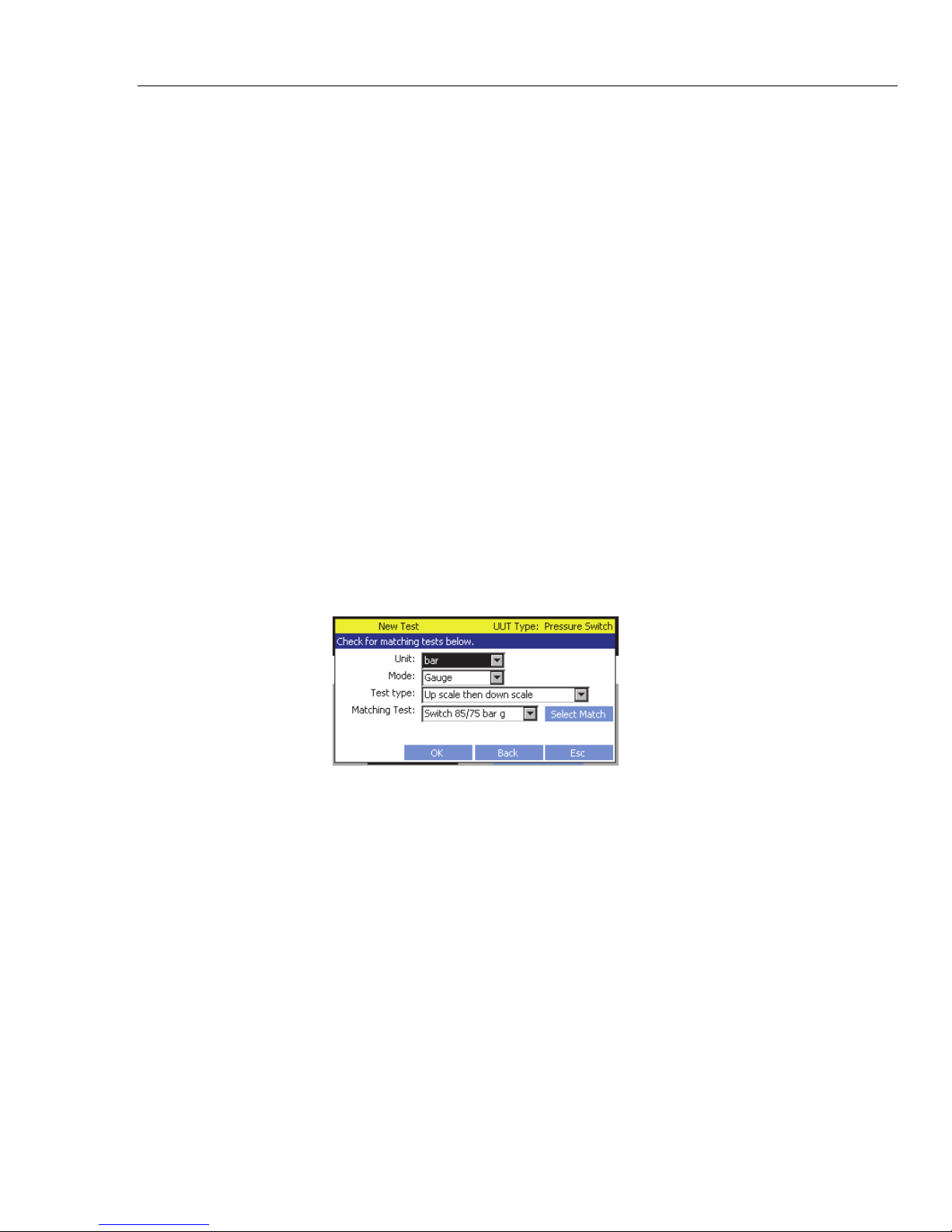
Controller Operation
Test a UUT 3
7. Change the test name (if required).
8. Push to save the test and exit to the Main test menu. The new test is
loaded and is now shown on the Main test menu.
9. Run the Test Sequence (see “Run a Test Sequence” on page 3-33 for instructions on
how to run the test).
Make a New Pressure Switch Test
Create a new pressure switch test as follows:
Note
The Gauge/Transducer New Test menu looks different and contains
different test settings than the Pressure Switch New Test menu. Figure 3-17
shows the two menus.
1. From the Main menu, select to open the run test menu.
Note
When is selected, the Controller uses the parameters contained
in the test file shown in the Test drop-down box to populate the initial
values of the new test. To make a new test quickly, select a similar test in
the Test drop-down box before is selected.
2. Select
Pressure Switch from the UUT Type drop-down box.
3. Select on the test menu to open the New Test menu.
4. Configure the test as follows:
Note
As a new test is being made and parameters are selected, the Controller
actively searches the saved test files for tests that have the same test
parameters. If the Controller finds a match, the Controller shows the test
matches in the Matching Test field. The Controller searches and updates
the Matching Test Field each time a field is changed. If the Matching Test
Field is selected and then is selected, the new test is not saved
and the Controller opens the test menu with the matching test loaded.
f. Select a pressure unit from the
g. Select a measurement mode from the
Unit drop-down box.
Mode drop-down box.
h. Select a test direction from the
i. Push to continue.
5. Configure the test limits as follows:
Test Type field.
3-33
Page 88
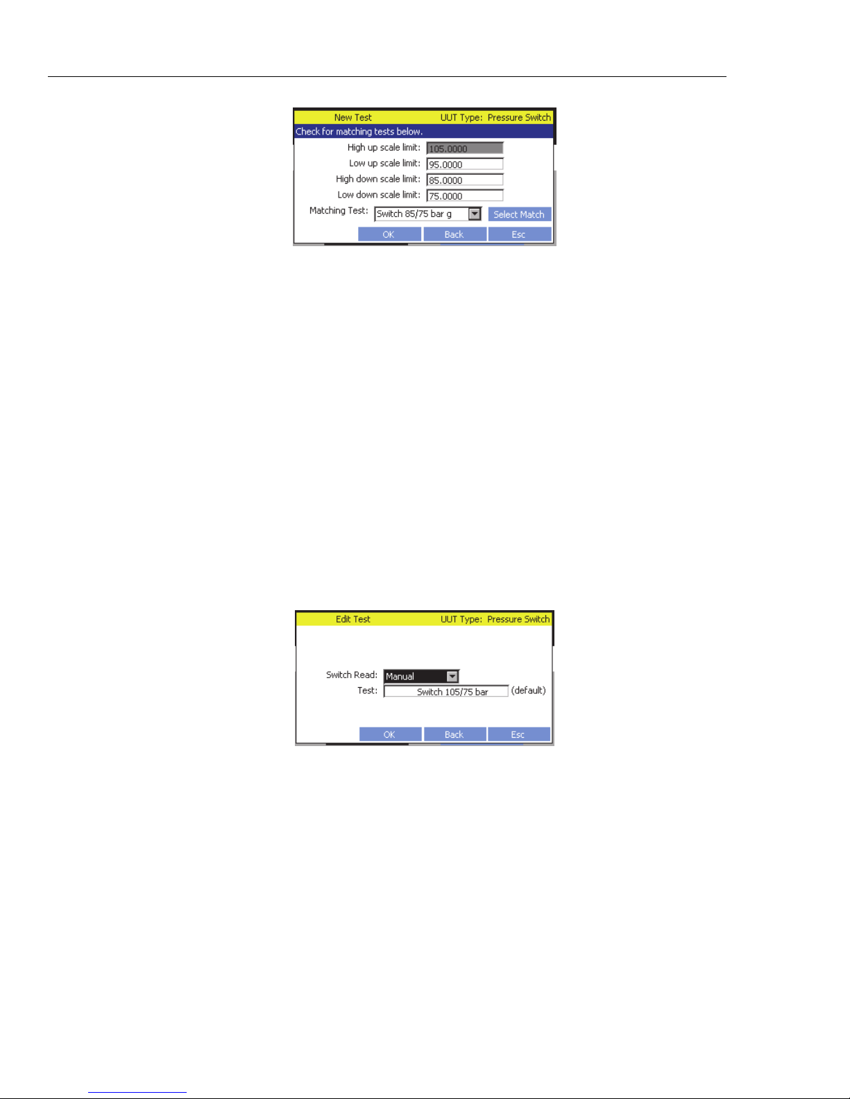
4322
Operators Manual
a. Select and key in the High up scale limit pressure value.
b. Select and key in the
c. Select and key in the
d. Select and key in the
Low up scale limit pressure value.
High down scale limit pressure value.
Low down scale limit pressure value.
e. Push to continue.
6. Set the Switch Read to
Manual or Automatic.
Note
Pressure switches are electro-mechanical devices that change their output
state (on or off) at a prescribed pressure value. These states are usually
associated with the opening and closing of an electrical circuit as a result
of the change in pressure. The open or closed state of the electrical circuit
can be read with a continuity checker. The Handheld Control has a built in
continuity check function that communicates with the Controller. If Switch
Read is set to Automatic, the Handheld automatically measures the
pressure that the pressure switch changed its state. If the Switch Read is set
to Manual, the user pushes
to manually measure the pressure that
the pressure switch changed its state.
7. Change the test name (if required).
3-34
Page 89

Controller Operation
Test a UUT 3
Run a Test Sequence
A Test Sequence lets the user fully configure and run a test to calibrate a UUT. After a
Test Sequence is complete, the results can be printed to a test report. See “Test Files” for
instructions on how to make a new test, edit a saved test, and manage saved tests.
Note
Before a Test Sequence is run, the user must decide whether to use the
Handheld Control or the control panel on the Controller.
To run a Test Sequence:
1. Connect the Controller to Intensifier or the Nitrogen Cylinder supply and set up the
supply (see “Set the Internal and External Supply Setting” in Chapter 2.
2. Prepare and connect to a UUT (see “Connect to a Unit Under Test (UUT)” in
Chapter 2).
3. Turn on the Intensifier and select a boost pressure, if required (see “Set Boost
Pressure” in Chapter 4).
Note
Boost pressure selection is dependent on the pressure necessary to
complete the UUT calibration. For a typical UUT calibration, select a
boost pressure equal to or greater than the maximum pressure necessary to
complete the UUT calibration. For multiple UUT calibrations in the same
location, set the boost pressure to the lowest available selection that is
higher than the highest pressure necessary to complete the UUT
calibrations. The higher the target supply selection, the faster the Nitrogen
Supply discharges.
4. Select on the Main menu to open the Run Test menu.
5. Select a UUT type from the
UUT Type drop-down box.
6. Select a test from the Test drop-down box (see “Test Sequences” on page 3-26).
7. Select to continue.
8. Follow the on-screen instructions to set the Internal or External supply setting. Select
to continue.
9. Perform a Hose Purge, System Purge, Leak Test, or Exercise a gauge. Once finished,
select or to continue.
Note
The hose purge, leak test, or exercise can be run from this menu. If a tool is
run, make sure to select to return to the test menu. If
selected, the Test menu closes.
3-35
Page 90

4322
Operators Manual
10. Run the test as follows:
a. On the run test menu, select to run the test when ready. The
Controller controls pressure to the first target pressure test point and controls the
pressure with the set control mode set in the test settings.
b. Push
c. Select . The Controller controls pressure to the next target pressure
d. Push
e. Repeat steps c. and d. again for the remainder test points.
f. After all test points are complete, select to open the test results menu.
11. Fill in the UUT information on the UUT information menu then select to
open up the run test menu.
The information on this menu is used to populate the calibration report.
12. Select to close and save the test results or to print the test
results.
Ready.
test point.
Ready.
To print the test results, connect and turn on the printer. If a printer is
not available at the conclusion of the test, the test results can be viewed
at a later time and printed from the Run Test menu. To see previous test
results, select the test from the Test drop-down menu and select “Past
Results”.
to make a measurement when the measurement indicator shows
Note
Use to redo a test point.
to make a measurement when the measurement indicator shows
Note
Note
3-36
Page 91
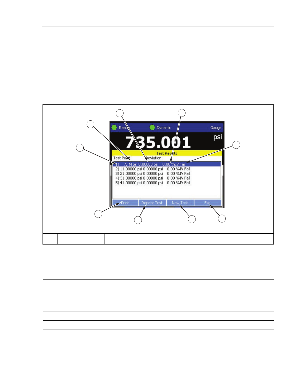
Controller Operation
View Test Results 3
View Test Results
After a test is complete, the test results can be viewed on the Test Results menu. The Test
Results menu shows each test point, target pressure, deviation pressure, deviation
percentage, and whether the UUT passed or failed the test point.
To determine the pass or fail criteria, the Controller compares the reference value (the
Controller) to the UUT value (UUT reading). If the difference between these two values
is greater than the UUT tolerance that was set when the test was configured, the
Controller shows “Fail” for that test point.
Table 3-12. Test Results Menu
3
2
1
6
Item Name/Button
Test Point Test point number.
4
5
7
8
Function
9
gxj073.eps
Target Pressure The target pressure of the test point.
Deviation The amount of deviation between the reference value and the UUT value.
Percent of Deviation Deviation in percentage format.
Pass or Fail Indicator
Print Print the results on a formal test report (see “Print Report” on page 3-38).
Repeat Test Repeat the test on the UUT. The results will have a new timestamp.
New Test Opens the Run Test menu to run a new test.
Esc Cancel and return to the Main menu.
Shows “Fail” if the amount of deviation is more than the UUT tolerance and shows
“Pass” if within the UUT tolerance.
3-37
Page 92
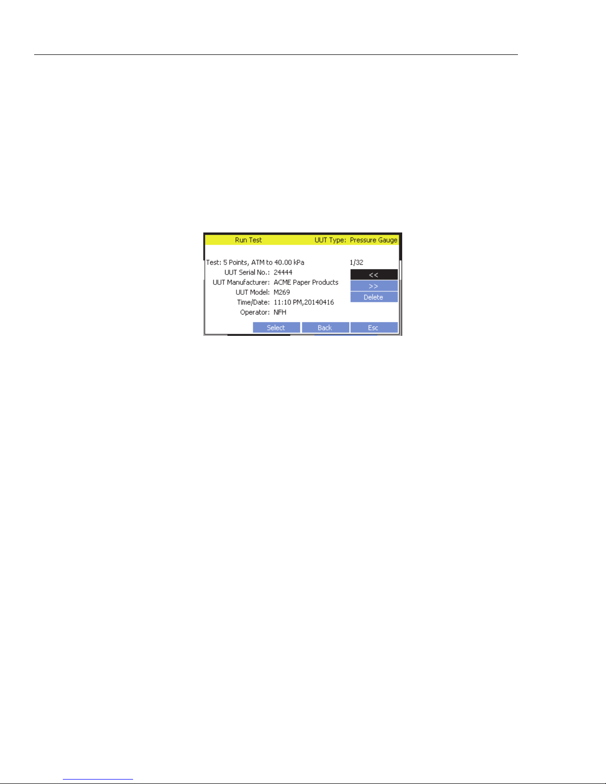
4322
Operators Manual
View Past Results as follows:
1. Select on the Main menu to open the Run Test menu.
2. Select a UUT type from the
3. Select a test from the Test drop-down box (see “Find a Saved Test” on page 3-29).
4. Select to open the Find Results menu.
is hidden if there are no results stored for the selected test.
5. Use and to cycle through the results then select to
open the Test Results menu.
6. View the test results on the menu or print a report (see “Print a Test Report”).
Print a Test Report
From the Test Results menu, a Test Report can be printed that contains the UUT
information and also the test results.
UUT Type drop-down box.
Note
To connect a printer and print a report:
1. Connect the printer to the Printer port on the Controller.
Note
The printer must natively support the PCL5 standard. Printers that emulate
the PCL5 standard may not function properly. Printers that require a driver
to support PCL5 (“Host based printing”) will not work. Consult your
printer manufacture for the details about your printer.
2. Select on the Main menu then select the Remote tab.
3. Select
Print Test Page. The Controller sends a test page to the printer. If the printer
prints the test page, print the test report. See “View Test Reports” to find the test
results to print. If the printer does not print a test page:
a. Check the connections.
b. Check to make sure the printer is on, ready, and has paper loaded.
c. Check the printer for error messages and retry.
3-38
Page 93

Chapter 4
Intensifier Operation
Title Page
Introduction ........................................................................................................ 4-3
Turn On the Intensifier ...................................................................................... 4-3
Choose a Boost Pressure .................................................................................... 4-3
Set Boost Pressure ............................................................................................. 4-4
Vent the System ................................................................................................. 4-5
Isolate Pressure .................................................................................................. 4-5
4-1
Page 94

4322
Operators Manual
4-2
Page 95

Intensifier Operation
Introduction 4
Introduction
This chapter supplies boost pressure information and instructions on how to set the boost
pressure on the Intensifier.
Turn On the Intensifier
To turn on the Intensifier, connect the mains power cord and toggle the power switch to
the (I) position. The internal electronics will perform a self-check. If any problems are
encountered, the LEDs on the front panel will indicate what error is present. See
Chapter 6 for troubleshooting information.
Choose a Boost Pressure
The Pressure Intensifier (the Intensifier) is an electric pressure booster system that can
boost gas pressure supply from (500 to 3,000) psig up to 10,000 psig. The Intensifier has
a pressure selection control panel, a pressure gauge, vent and isolation pressure valves,
and QC supply and outlet ports.
Note
To drive the Intensifier, >500 psi nitrogen supply is necessary (not to
exceed 2,000 psi). Operation of the Intensifier with <500 psi is not
recommended as performance of the Intensifier will be degraded and could
cause extra wear on the system.
When a boost pressure is selected, an electronically controlled servo motor drives a four
piston, mechanical boost pump. The rate of pressure accumulation is dependent on the
supply pressure, and the motor speed and test volume. The higher the supply pressure, the
faster the pressure generates. Pressure generated by the boost pump is stored in a 15 cc
internal accumulator and in the system pressure lines.
An electrical pressure sensor monitors and measures the pressure in the accumulator and
transmits pressure measurement values to the electronic motor controller. As the
measured pressure in the accumulator approaches the selected pressure value, the motor
controller decreases the rate of pressure generation. The speed of the motor changes as
necessary to hold the selected pressure in the system (referred to as “Pressure on
Demand”).
Note
The Intensifier is not made to store pressure when not in operation. After
is pushed, pressure slowly bleeds from the accumulator.
The Intensifier continuously supplies the pressure selected until is pushed. This
makes sure that the Controller has sufficient pressure available to complete the UUT
calibration.
4-3
Page 96

4322
Operators Manual
Set Boost Pressure
Boost pressure selection is dependent on the pressure necessary to complete the UUT
calibration. For a typical UUT calibration, select an intensifier pressure equal to or
greater than the maximum pressure necessary to complete the calibration.
Note
The Intensifier boost pressure is typically 5% to 8 % higher than the set
pressure requested. This feature allows the set pressure to be equal to the
maximum pressure required for calibration.
For multiple UUT calibrations in the same location, set the boost pressure to the lowest
available selection that is higher than the highest pressure necessary to complete the UUT
calibrations.
Note
The higher the target supply selection, the faster the Nitrogen Supply
depletes.
Set a boost pressure as follows:
1. Connect the Intensifier to the Nitrogen Cylinder and the Controller. See “Configure
the Pressure Supply” in Chapter 2.
2. Turn on the Intensifier.
3. Close the Vent Valve and fully open the Isolation Valve.
4. Use the Target Boost Pressure selection keys to select a boost pressure. After a boost
pressure is selected, the green LED to the right of the key illuminates and stays
illuminated until is pushed. If the LED next to the key does not illuminate after
a boost pressure selection, refer to “Pressure Selection and LED Indications” in
Chapter 6.
Notes
• The Intensifier is a pressure on demand system and automatically
generates pressure as necessary to keep the pressure at the selected
boost pressure.
• Intensifier pressure selection is dependent on the pressure
necessary to complete the UUT calibration. For a typical UUT
calibration, select a boost pressure equal to or slightly greater than
the maximum pressure necessary to complete the UUT calibration.
The Intensifier will generate a pressure slightly higher than the
selected intensifier pressure. This reduces the risk of a UUT
overpressure and prolongs pump life by optimizing pump speed to
the required pressure range.
• For multiple UUT calibrations in the same location, set the boost
pressure to the lowest available selection that is higher than the
highest pressure necessary to complete the UUT calibrations. The
higher the target supply selection, the faster the Nitrogen Supply
discharges.
5. When finished, push or turn off the Intensifier to stop pressure generation.
6. Open the Vent Valve to vent the pressure from the Intensifier and the QC fittings.
4-4
Page 97

Intensifier Operation
Vent the System 4
Vent the System
Vent the Intensifier as follows:
1. Push to turn off pressure generation.
2. Turn off the Nitrogen Cylinder Regulator.
3. Turn the Vent Valve counterclockwise to vent the pressure.
Caution
To prevent damage to the knob, do not force the knob after it
reaches the full open or closed position.
Note
Pressure from the entire system will be vented if the Vent Valve is opened
when the Isolation valve is open. If the Isolation Valve is closed when the
Vent Valve is opened, only the pressure in the Intensifier will be vented.
4. After vented, turn the Vent Valve clockwise to close the valve.
Isolate Pressure
The Isolation valve lets the operator isolate the Intensifier pressure from the rest of the
system. When the Isolation Valve is closed and the Vent valve is open, the pressure is
released and the QC fitting can be removed from the Outlet Port.
Isolate pressure in the Intensifier as follows:
1. Turn the Isolation Valve clockwise to close the valve.
Caution
To prevent damage to the valve, do not force the knob after it
reaches the full open or closed position.
2. Slowly turn the Vent Valve counterclockwise to vent the pressure out of the system
between, but keep the Intensifier pressurized.
3. After vented, turn the Vent Valve clockwise to close the valve and turn the Isolation
Valve counterclockwise to resume normal operation.
4-5
Page 98

4322
Operators Manual
4-6
Page 99

Chapter 5
Remote Operation
Title Page
Introduction ........................................................................................................ 5-3
USB Remote Interface Setup ......................................................................... 5-4
IEEE-488 (GPIB 488.2) Remote Interface Setup .......................................... 5-4
Remote Operation Commands ........................................................................... 5-4
Overview of Command Structures ................................................................ 5-4
Alphabetical List of Remote Commands ....................................................... 5-5
Remote Command Format ............................................................................ 5-7
Common and Status Commands.................................................................... 5-8
Specific Commands ....................................................................................... 5-9
488.2 Status System ........................................................................................... 5-17
Status Byte Register ...................................................................................... 5-17
Standard Event Register ................................................................................ 5-19
Ready Status Register .................................................................................... 5-19
Operation Status Register .............................................................................. 5-20
Remote Errors .................................................................................................... 5-20
5-1
Page 100

4322
Operators Manual
5-2
 Loading...