

Page 1

312, 316, 318
Clamp Meter
®
Users Manual
PN 1989445
July 2002 Rev.2, 2/06
© 2002, 2006 Fluke Corporation. All rights reserved. Printed in China.
All product names are trademarks of their respective companies.
Page 2

LIMITED WARRANTY AND LIMITATION OF LIABILITY
This Fluke product will be free from defects in material and
workmanship for one year from the date of purchase. This
warranty does not cover fuses, disposable batteries, or
damage from accident, neglect, misuse, alteration, contamination, or abnormal conditions of operation or handling.
Resellers are not authorized to extend any other warranty
on Fluke’s behalf. To obtain service during the warranty
period, return the unit to point of purchase with a description of the problem.
THIS WARRANTY IS YOUR ONLY REMEDY. NO OTHER
WARRANTIES, SUCH AS FITNESS FOR A PARTICULAR
PURPOSE, ARE EXPRESSED OR IMPLIED. FLUKE IS
NOT LIABLE FOR ANY SPECIAL, INDIRECT, INCIDENTAL OR CONSEQUENTIAL DAMAGES OR LOSSES,
ARISING FROM ANY CAUSE OR THEORY. Since some
states or countries do not allow the exclusion or limitation of
an implied warranty or of incidental or consequential damages, this limitation of liability may not apply to you.
Fluke Corporation
P.O. Box 9090
Everett, WA 98206-9090
U.S.A.
Service Center Address:
Fluke Corporation Beijing Service Center
Room 2301 Scite Tower
22 Jianguomenwai Dajie, Chao Yang District
Beijing 100004, PRC
Tel: 010-65123435
Shanghai ShiLu Instrument Co., Ltd.
No. 139, Lane 2638, Hongmei South Road
Shanghai 201108
Standard No. Q/SXAV 2-2002
Page 3

Table of Contents
Title Page
Safety Information – Read first.........................1
General Specifications .....................................4
Electrical Specifications....................................5
Instrument Overview Feature Locations...........6
Symbol Definition...........................................7
Making Measurements .....................................7
Measuring AC Current ...................................8
Measuring DC Current (316, 318 only) ..........9
Measuring AC and DC Voltage ......................9
Measuring Resistance ...................................12
Testing Continuity ..........................................13
Diode Test......................................................14
Data Hold.......................................................15
Peak...............................................................15
MIN MAX (316, 318 only)...............................15
REL (S) (316, 318 only) ................................16
Range (312 only) ...........................................16
Changing the Battery........................................16
Cleaning the Meter...........................................16
Maintenance.....................................................16
i
Page 4

ii
Page 5

312, 316, 318
Safety Information – Read first
WWarnings: Read Before Using
To avoid possible electric shock or personal injury:
• Use the Meter only as specified in this manual or the
protection provided by the Meter might be impaired.
• Do not use the Meter in wet environments.
• Inspect the Meter before using it. Do not use the Meter
if it appears damaged. Look for cracks or missing
plastic. Pay particular attention to the insulation
around the connectors.
• Inspect the test leads before use. Do not use them if
insulation is damaged or metal is exposed. Check the
test leads for continuity. Replace damaged test leads
before using the Meter.
• Have the Meter serviced only by qualified service
personnel.
• Do not apply more than the rated voltage, as marked
on the Meter, between the terminals or between any
terminal and earth ground.
• Remove test leads from the Meter before opening the
Meter case.
• Never operate the Meter with the back cover removed
or the case open.
• Never remove the back cover or open the case of an
instrument without first removing the power source.
• Use caution when working with voltages above 33 V ac
rms, 46.7 V ac peak, or 70 V dc. These voltages pose a
shock hazard.
• Use the proper terminals, function, and range for your
measurements.
• Do not operate the Meter around explosive gas, vapor,
or dust.
1
Page 6

312, 316, 318
• When using probes, keep your fingers behind the
finger guards.
• When making electrical connections, connect the
common test lead before connecting the live test lead;
when disconnecting, disconnect the live test lead
before disconnecting the common test lead.
• Disconnect circuit power and discharge all high-
voltage capacitors before testing resistance,
continuity, or diodes.
• Use only a single 9 V battery, properly installed in the
Meter case, to power the Meter.
• Replace the battery as soon as the low battery
indicator (
lead to electric shock and injury.
• Check Meter operation on a known source before and
after use.
• When servicing, use only specified replacement parts.
• Adhere to local and national safety codes. Industrial
protective equipment must be used to prevent shock
and arc blast injury where hazardous live conductors
were exposed.
• Do not hold the Current Probe anywhere beyond the
tactile indicator (see Figure 1).
B) appears to avoid false readings that can
Environmental Conditions:
Altitude: up to 2000 meters.
Operating temperature: 0 °C ~ 30 °C, up to 90 % RH, non-
condensing
30 °C ~ 40 °C, up to 80% RH, non-condensing
Storage temperature: -10 °C ~ 60 °C, battery removed
Pollution Degree: 2
Measurement Categories: CAT III (600 V), CAT II (1000 V)
Electromagnetic Compatibility: 3 V/m, performance criterion B
2
Page 7
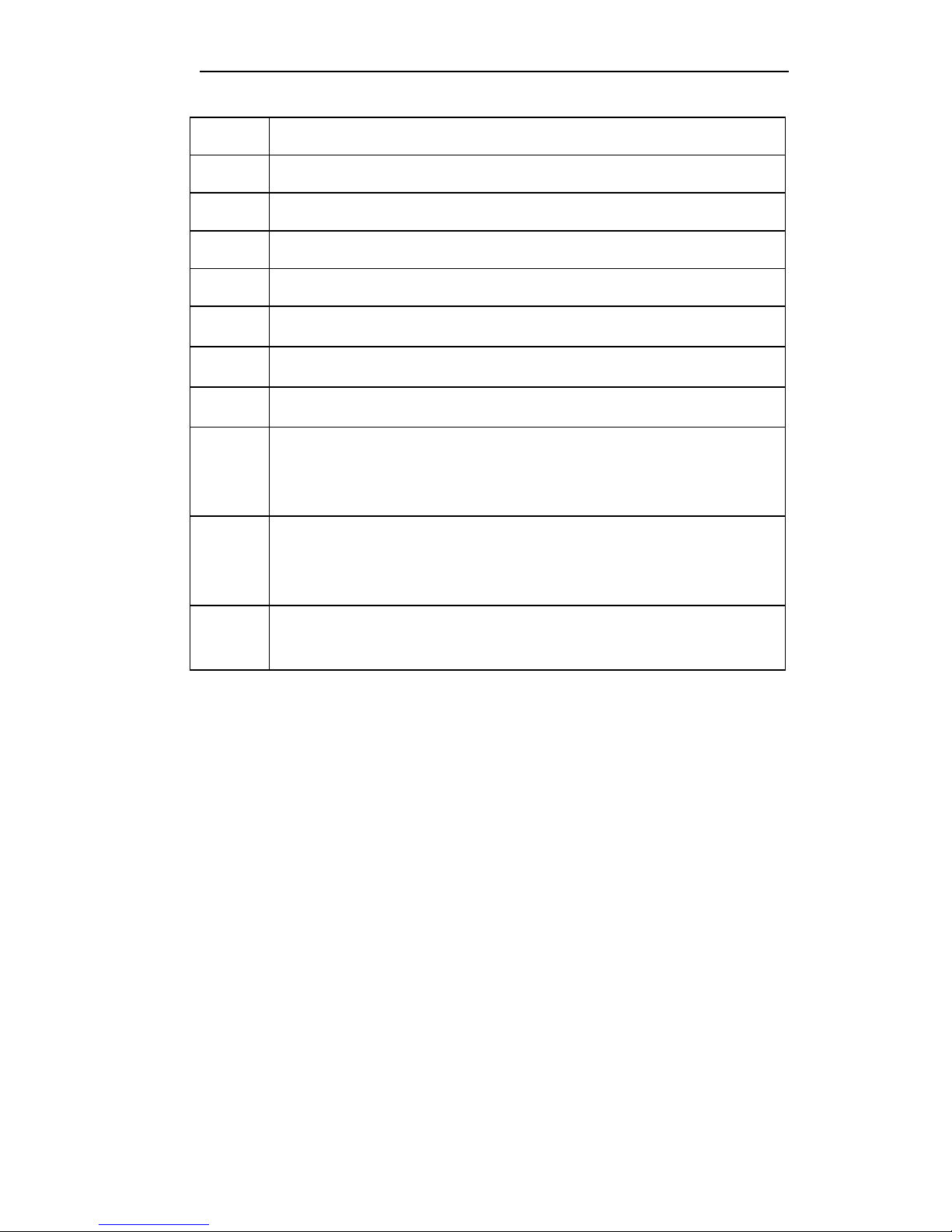
Explanation of Symbols
Users Manual
W
X
,
T
B
J
B
F
CAT II
CAT III
Risk of danger. Important information. Refer to operation instructions.
Risk of electric shock.
Application and removal from hazardous live conductors permitted.
Double insulated.
Battery
Earth Ground
Alternating current
Direct current
Equipment is designed to protect against transients from energy-consuming
equipment supplied from the fixed installation, such as televisions, personal
computers, portable tools, and other household appliances.
Equipment is designed to protect against transients in equipment in fixedequipment installations, such as distribution panels, feeders and short branch
circuits, and lighting systems in large buildings.
P
Complies with European standards EN/IEC 61010-1 2nd Edition and EN/IEC
61010-02-032
3
Page 8

312, 316, 318
General Specifications
Digital Display: 3-3/4 digits with maximum reading of 3999
Analog Display: Fast 42-segment analog bar graph display
Overload: Displays OL when input signal exceeds measuring limit
in 40 A, 400 A, resistance, and continuity functions.
Note
In Volts and Amps, the LCD may continue to display
values above the indicated measuring limit (up to 4000
counts). Refer to specifications for measuring limits.
Sample Rate: 2 times/sec for digital display; 20 times/sec for
analog bar graph
Low Battery Indication: Displays
required voltage
Power Source: 9 V battery, NEDA1604 or 6F22 or 006P
Battery Life:
(Alkaline):
33 hrs typical in A
65 hrs typical in GR
100 hrs typical in V, e
Auto Power Off: The Meter will power itself off if there is no push
button or rotary function switch operation for 30 minutes. Turn the
rotary switch to “OFF” before turning the Meter on again.
To deactivate this feature, press the Peak button and keep it
pressed down while powering up the Meter.
Clamp Opening Size:
312: 36 mm (1.42 inches)
316, 318: 40 mm (1.57 inches)
Dimensions (L x W x H): 254 x 66 x 37 mm (10 x 2.60 x 1.45
inches)
Weight: 422 g (14.9 ounces) (battery included)
B when the battery is below its
Included Accessories: Users manual, carrying case, test leads,
9 V battery
Approvals:
P, EN61010 600 V CAT III, 1000 V CAT II, CMC
4
Page 9
Users Manual
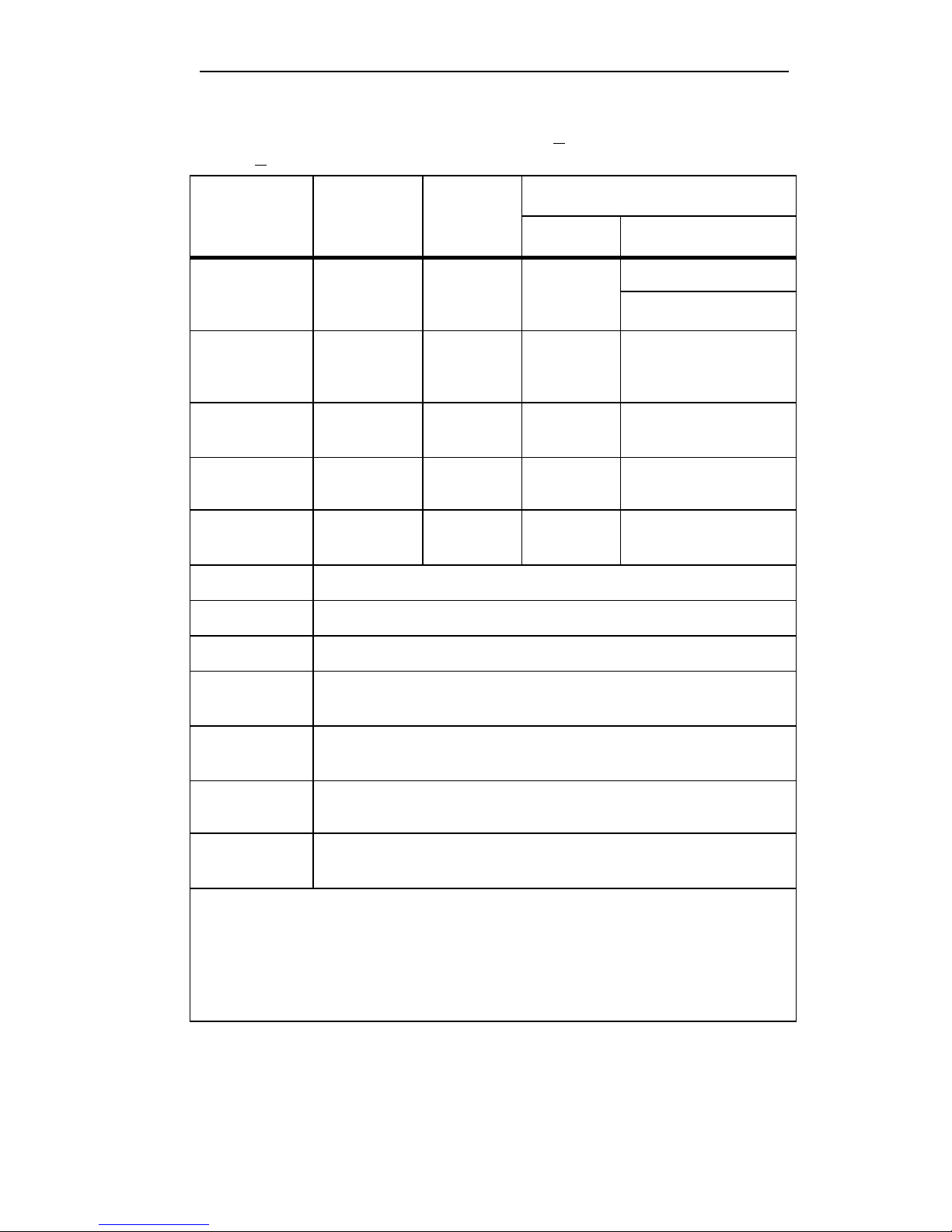
Electrical Specifications
The accuracy specification is defined as + (% reading + digits) at
o
23
C + 5 oC1.
Function
AC Amps
2
(50 ~ 500 Hz)
DC Amps
AC Volts
2
(50 ~ 500 Hz)
DC Volts
Resistance
(ohms)
Continuity
Diode Test
Range
40.00 A
400.0 A
1000 A
40.00 A
400.0 A
1000 A
400.0 V
750 V
400.0 V
1000 V
400.0 Ω
Ω
4000
On at < 50 Ω
Up to 2 V
Resolution
0.01 A
0.1 A
1 A
0.01 A
0.1 A
1 A
0.1 V
1 V
0.1 V
1 V
0.1
Ω
Ω
1
Accuracy (% reading + digits)
312
1.9 %
±
5
1.9 % ± 5 (50 ~ 60 Hz)
2.5 %
- 2.5 %
1.2 %
±
5 1.5 % ± 5
0.75 %
1 %
±
2 1 % ± 2
±
3 1 % ± 3
316 & 318
±
5 (60 - 500 Hz)
±
10
Min Max
Input
500 ms acquisition time
10 MΩ
Impedance
Auto
Shut-off
Auto range
Overload
Protection
After 30 min ± 2 min. Disabled in Min Max. Can be disabled as a power up
option (hold down the peak button)
Available in the following measurement functions: Volts & Ohms (Amps for
312 only)
600 Vrms per EN61010 CAT III 600 V
1. Temperature Coefficient: 0.1 x (specified accuracy) / oC (< 18 oC or > 28 oC)
2. True rms for ac voltage and ac amps accuracy is specified from 5 % to 100 % of range. Crest
factor (50 ~ 60 Hz) is 3.0 max in the 40 A and 400 A ranges and 1.4 max in the 1000 A
range (318 only).
3. The measurement time for current above 400 A is limited to 5 minutes followed by a
cooling off time of 15 minutes.
5
Page 10
312, 316, 318
Instrument Overview
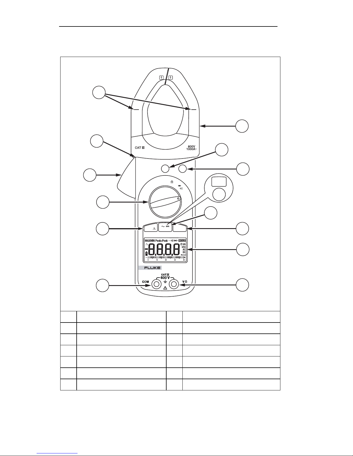
Feature Locations
13
14
12
400
40
A
11
OFF
OFF
1000
A
PEAK HOLD
PEAK HOLD
A
1
2
3
RANGE
V
4
5
10
9
A
Current Sensing Clamp
B
Peak Button
C
Hold Button
D
Range Button (312)
E
AC/DC Button (316, 318)
F
MIN MAX Button (316, 318)
G
LCD
AC/DC MIN MAXREL
318
TRUE RMS
CLAMP METER
H
V e
Input Terminal
I
COM
Terminal
J
REL Button (316, 318)
K
Rotary Function Switch
L
Clamp-opening Trigger
M
Conductor Alignment Marks
N
Tactile Indicator
6
7
8
aca11f.eps
Figure 1. Feature Locations (318 shown)
6
Page 11
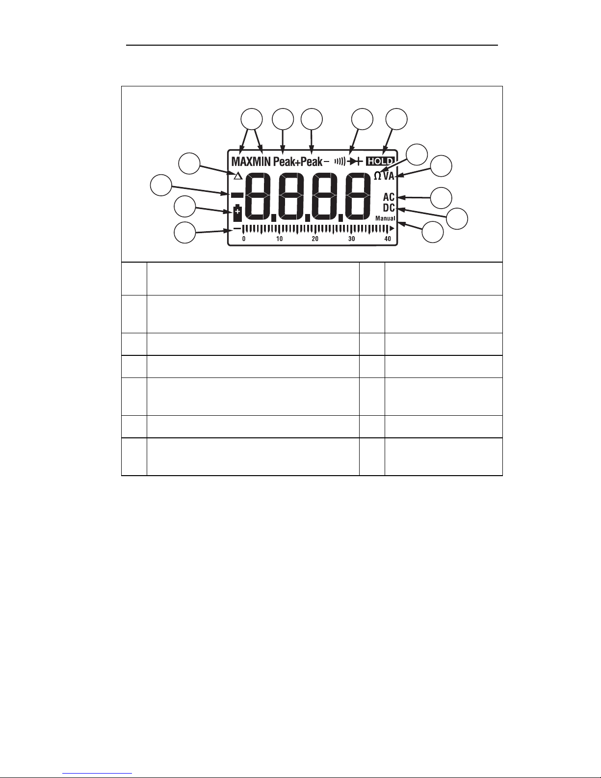
Symbol Definition
1 14 13 12 11
Users Manual
2
3
4
5
MAX
A
B
C
D
E
F
Maximum reading displayed (316, 318 only)
MIN
Minimum reading displayed (316, 318 only)
Relative (S) mode is active
Negative reading
Battery is low and should be changed
Bar graph
Manual range mode
10
6
H
AC mode
V
I
J
K
L
M
Volts
A
Amps
e
Ohms
Hold function is selected
Diode/continuity test
function is selected
Peak- function is selected
9
8
7
aca02f.eps
G
DC mode
Figure 2. LCD Explanation
Making Measurements
XWarning
• When measuring current, center the conductor in the
clamp using the alignment marks on the clamp.
• To avoid electrical shock when making current
measurements, disconnect the test leads from the
Meter.
• The bargraph is for reference only; it does not show
the actual measured value or range. Use the main
display to read the actual measured value and range.
Peak+ function is
N
selected
7
Page 12
312, 316, 318
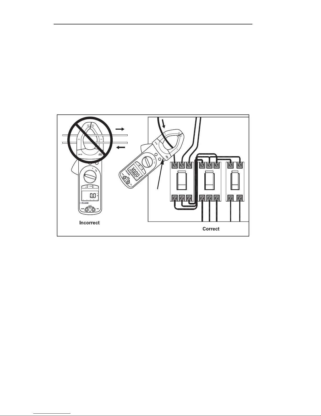
Measuring AC Current
1. Turn the rotary function switch to the proper current range.
2. Press
A(316, 318 only) to measure ac current if necessary.
3. Open the clamp by pressing the clamp-opening trigger and
insert the conductor to be measured into the clamp.
4. Close the clamp and center the conductor using the alignment
marks.
5. View the reading on the LCD.
400
PEAK
PEAK
40
1000
A
A
OFF
OFF
A
HOLD
M
A
X
HOLD
V
Tactile
Barrier
PEAK HOLD
PEAK HOLD
1000
A
A
400
V
A
40
OFF
OFF
AC/DC MIN MAXREL
TRUE RMS
318
CLAMP METER
R
E
L
A
C
/D
C
M
IN
318
TRUE RMS
CLAMP METER
Figure 3. Connecting the Clamp Meter (318 shown)
aca13f.eps
8
Page 13

Users Manual
Measuring DC Current (316, 318 only)
1. Turn the rotary function switch to the proper current range.
2. Press
3. To ensure accuracy, wait for the reading to stabilize then
press
4. Open the clamp by pressing the clamp-opening trigger and
insert the conductor to be measured into the clamp.
5. Close the clamp and center the conductor using the alignment
marks.
6. View the reading on the LCD.
A to measure dc current.
Q to zero the reading.
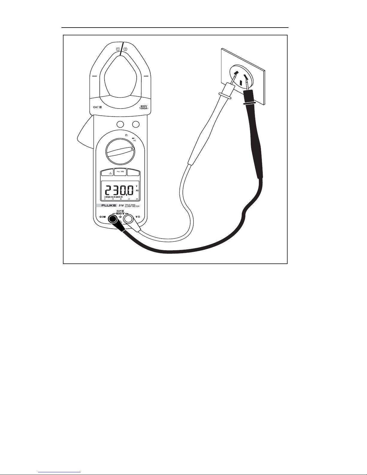
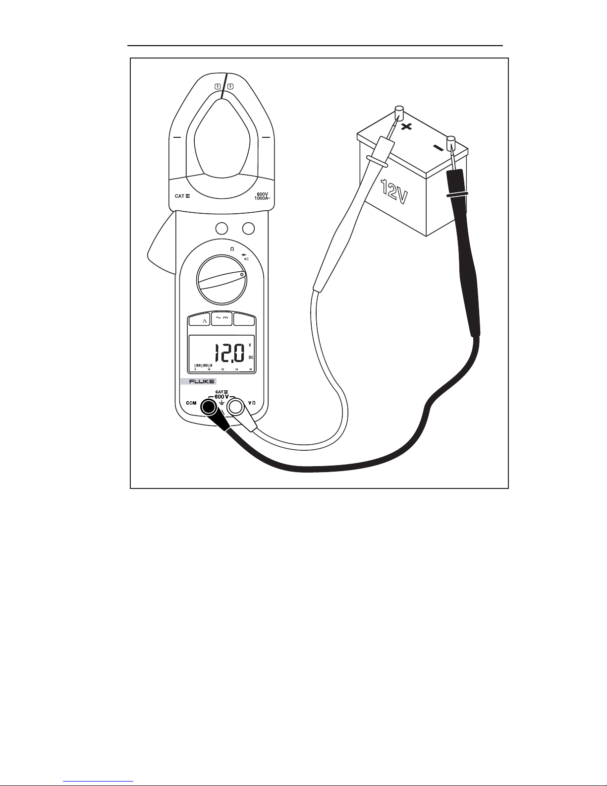
Measuring AC and DC Voltage
1. Turn the rotary function switch to V.
2. Choose ac or dc by pressing A(316, 318 only).
When using a 312 Meter:
• turn the rotary function switch to K when measuring ac
voltage
• turn the rotary function switch to L when measuring dc
voltage
3. Connect the black test lead to the COM terminal and the red
test lead to the Ve terminal.
4. Measure the voltage by touching the probes to the desired
test points of the circuit.
5. View the reading on the LCD.
9
Page 14
312, 316, 318
1000
A
400
A
40
OFF
OFF
PEAK HOLD
PEAK HOLD
A
AC/DC MIN MAXREL
V
Figure 4. AC Voltage Measurement (318 shown)
aca14f.eps
10
Page 15
40
OFF
OFF
400
A
1000
A
PEAK HOLD
PEAK HOLD
A
AC/DC MIN MAXREL
Users Manual
V
TRUE RMS
318
CLAMP METER
Figure 5. DC Voltage Measurement (318 shown)
aca15f.eps
11
Page 16
312, 316, 318
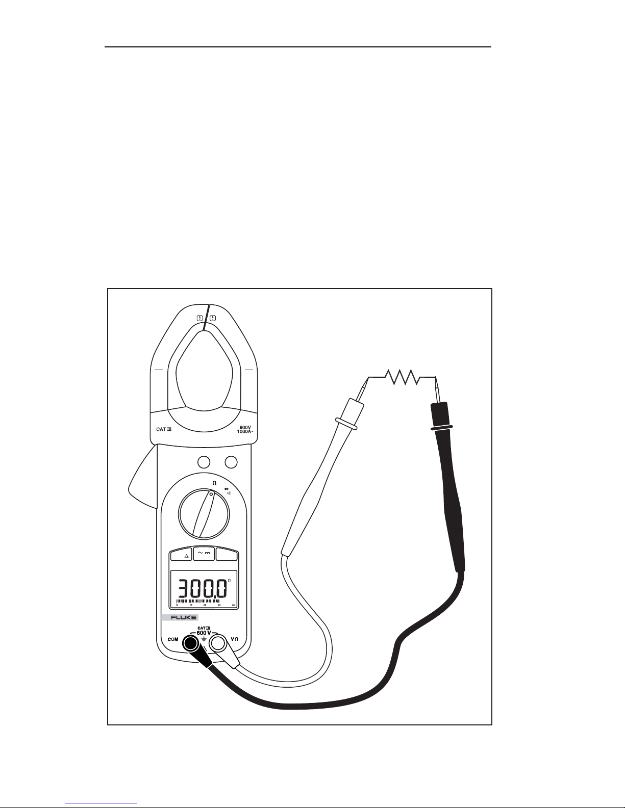
Measuring Resistance
XWarning
To avoid electrical shock when measuring resistance in a
circuit, make sure the power to the circuit is turned off and
all capacitors are discharged.
1. Turn the rotary function switch to e. Remove power from the
circuit being tested.
2. Connect the black test lead to the COM terminal and the red
test lead to the Ve terminal.
3. Measure the resistance by touching the probes to the desired
test points of the circuit.
4. View the reading on the LCD.
PEAK HOLD
PEAK HOLD
1000
A
400
A
A
40
OFF
OFF
AC/DC MIN MAXREL
318
TRUE RMS
CLAMP METER
V
Figure 6. Measuring Resistance (318 shown)
aca16f.eps
12
Page 17
Users Manual
Testing Continuity
XWarning
To avoid electrical shock when testing continuity in a circuit,
make sure the power to the circuit is turned off and all
capacitors are discharged.
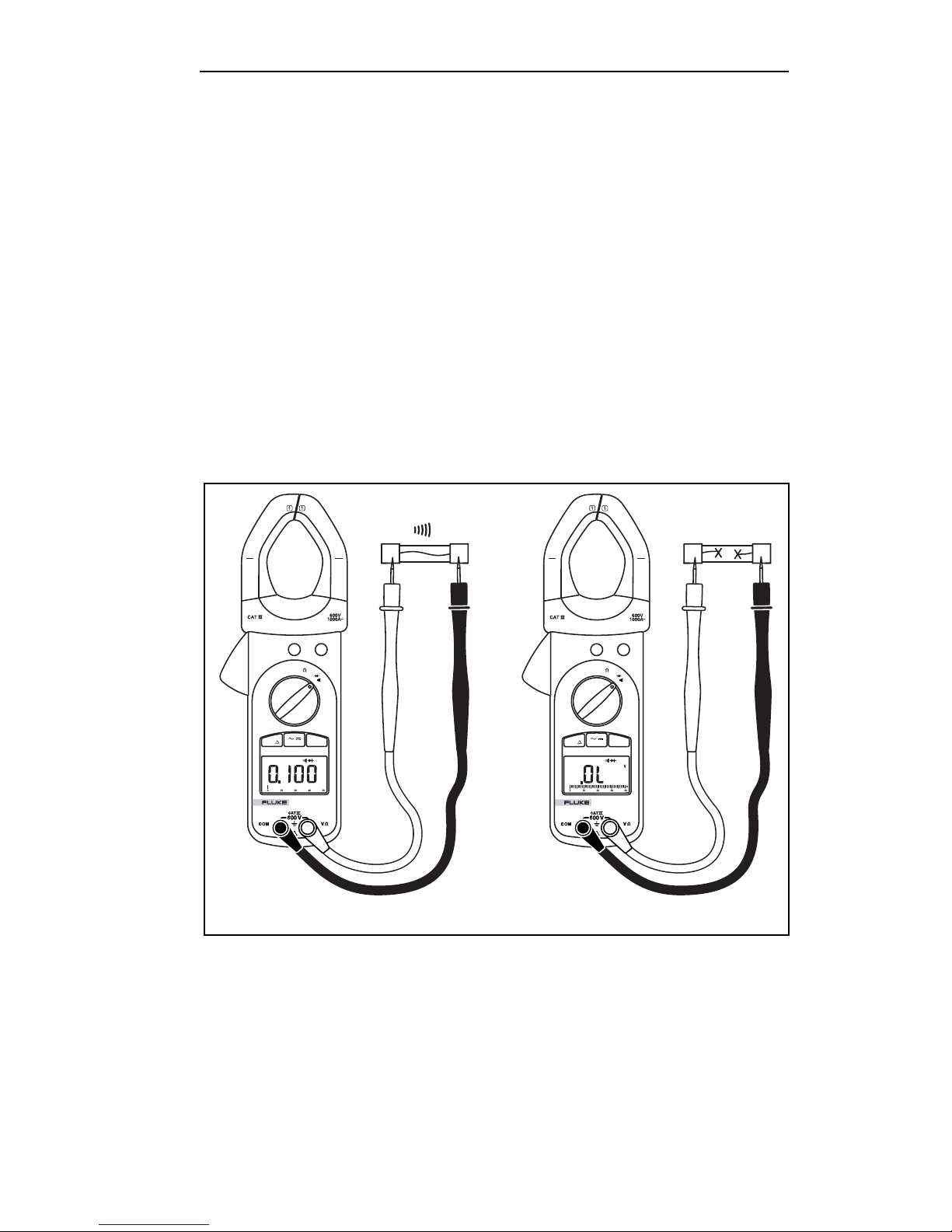
1. Turn the rotary function switch to D. Remove power from the
circuit being tested.
2. Connect the black test lead to the COM terminal and the red
test lead to the Ve terminal.
3. Connect the probes across the circuit or component to be
tested.
If the resistance is under 50 Ω, the beeper will sound continuously,
designating a short circuit. If the Meter reads OL, the circuit is
open.
PEAK HOLD
PEAK HOLD
1000
A
400
A
40
A
OFF
OFF
V
AC/DC MIN MAXREL
TRUE RMS
318
CLAMP METER
PEAK HOLD
PEAK HOLD
A
1000
400
A
40
A
OFF
OFF
V
AC/DC MIN MAXREL
TRUE RMS
318
CLAMP METER
Short Circuit Open Circuit
aca17f.eps
Figure 7. Measuring Continuity (318 shown)
13
Page 18
312, 316, 318
Diode Test
XWarning
To avoid electrical shock when testing diodes in a circuit,
make sure the power to the circuit is turned off and all
capacitors are discharged.
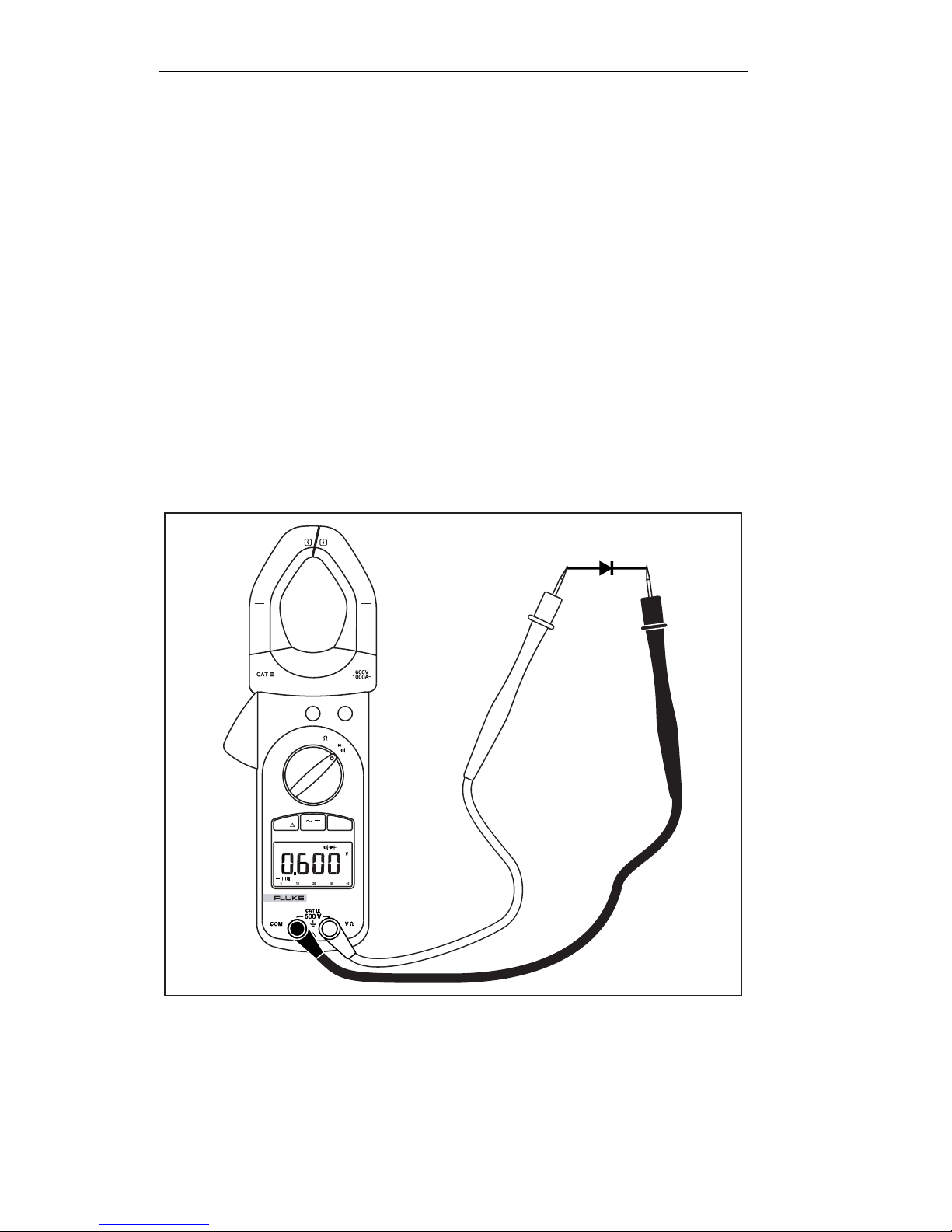
1. Turn the rotary function switch to D. Remove power from the
circuit being tested.
2. Connect the black test lead to the COM terminal and the red
test lead to the Ve terminal.
3. Connect the black test lead to the cathode side and the red
test lead to the anode side of the diode being tested.
4. Read forward bias voltage value on the LCD.
5. If the polarity of the test leads is the reverse of the diode
polarity, the LCD reading shows “OL”. This can be used for
distinguishing the anode side and cathode side of a diode.
PEAK HOLD
PEAK HOLD
A
1000
400
A
40
A
OFF
OFF
AC/DC MIN MAXREL
318
TRUE RMS
CLAMP METER
V
Figure 8. Diode Test (318 shown)
aca18f.eps
14
Page 19

Users Manual
XWarning
Dangerous voltages may be present at the input terminals
and may not be displayed.
Data Hold
To hold the present reading, press the HOLD button. Press the
button again to return to the live reading.
Peak
The Meter has a 1 ms peak feature for use with ACA, DCA (316,
318), ACV, and DCV functions. Before making a peak hold
measurement, the peak feature must be calibrated as follows:
1. Press and hold the peak button for 2 seconds. The CAL
indicator appears on the LCD to show that the offset has been
calculated and stored by the Meter.
2. After calibration, press the peak button once to enter Peak
mode and begin displaying Peak+ values.
3. Press the Peak button again to enter Peak
displaying Peak
4. Press the Peak button for 2 seconds to return to normal
operation.
- values.
- mode and begin
+
If the rotary function switch is changed following calibration, the
calibration steps must be repeated before making another peak
measurement.
Note
The peak mode continuously updates the LCD to show
maximum magnitudes. Smaller magnitudes are not
displayed.
MIN MAX (316, 318 only)
1. Press M once to set the Meter to MAX mode.
2. Press
3. Press
while keeping track of the MAX and MIN value. This mode is
also indicated by the blinking MAXMIN symbol on the LCD.
4. Pressing
to normal operation.
M again to set the Meter to MIN mode.
M again and the Meter displays the present reading
M for more than 2 seconds sets the Meter back
15
Page 20

312, 316, 318
REL (S) (316, 318 only)
1. Press Q to set the zero to the present reading. The
difference between the reference reading and subsequent
readings is displayed.
2. Press
reading. The blinking S on the LCD also indicates this mode.
3. Press
normal operation.
Q again and the Meter displays the reference
Q for more than 2 seconds to return the Meter to
Range (312 only)
Press R to select the manual range mode. Manual shows on
the LCD, and the Meter remains in the same range. To exit
manual-range mode and return to the auto-range mode, press and
hold
R for 1 second.
Changing the Battery
When the battery voltage drops below the value required for proper
operation, the battery symbol (B) appears on the LCD.
1. Before changing the battery, switch the Meter off and
disconnect the test leads.
2. Open the back cover using a screwdriver.
3. Replace the battery with a new 9 V battery.
4. Close the back cover and fasten the screws.
Cleaning the Meter
Periodically clean the Meter by wiping it with a dry cloth. Do not
use abrasives or solvents on this instrument.
Maintenance
XWarning
• To avoid electrical shock, disconnect test leads from
the Meter before removing its back cover. Never use
the Meter with the back cover removed.
• Repairs or servicing not covered in this manual should
be performed only by qualified personnel.
Caution
• To avoid contamination or static damage, do not touch
the circuit board without proper static protection.
• If the Meter is not going to be used for a long time,
remove the battery. Do not store the Meter in a high
temperature or a high humidity environment.
16
 Loading...