

Page 1
®
3005-PR
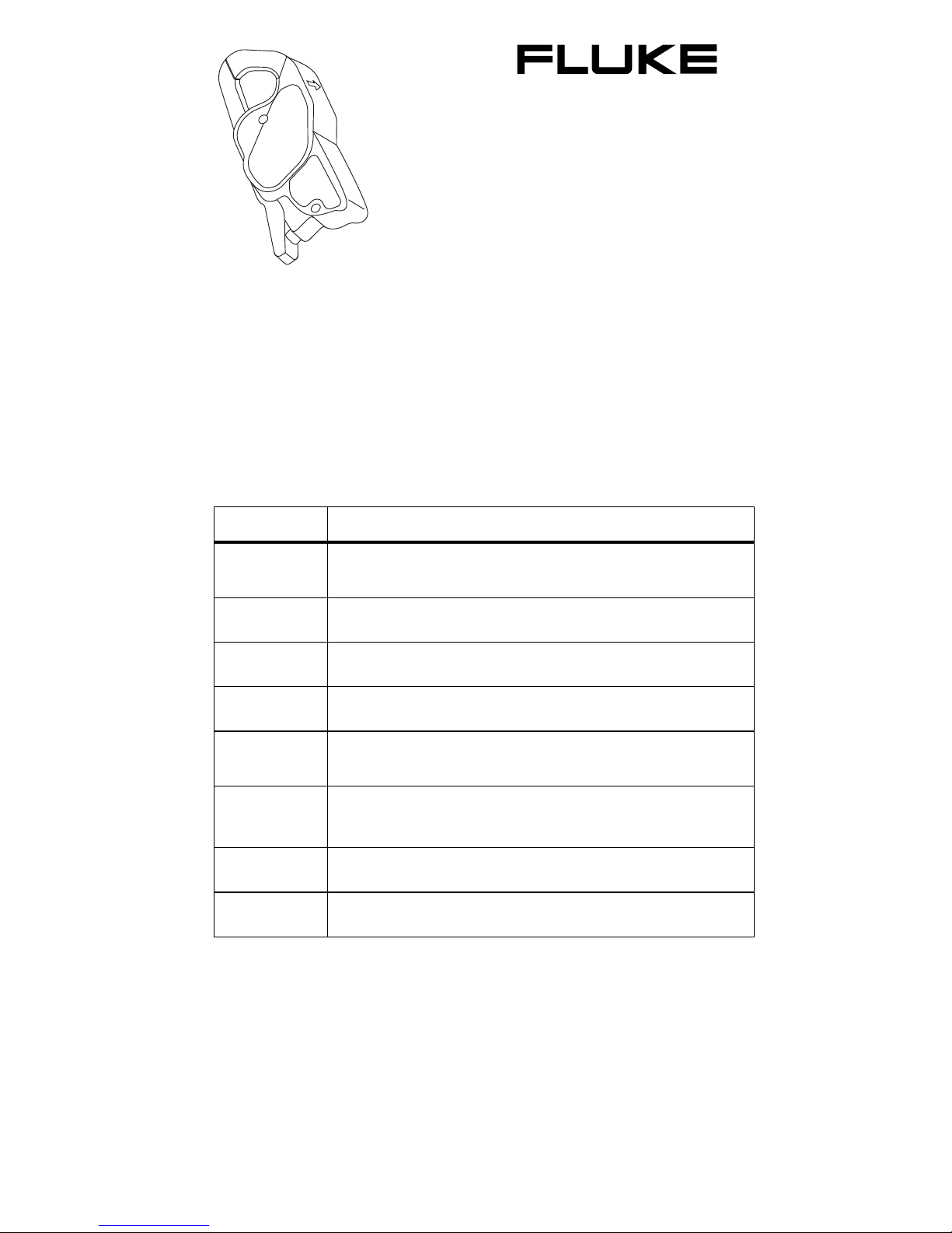
AC Current Clamp
Instruction Sheet
Introduction
The Fluke 3005-PR AC Current Clamp (“the Clamp”) is designed
for the Fluke 1750. Designed to meet the most stringent
demands in industry and electrical contracting, it also meets the
latest safety and performance standards.
Symbols
The table below lists the symbols used on the Clamp and/or in
this instruction sheet.
Symbol Description
~
W
X
T
,
@
P
;
Do not dispose of this product as unsorted municipal
waste. Go to Fluke’s website for recycling information.
Risk of danger. Important Information. See manual.
Hazardous Voltage. Risk of electric shock.
Double insulation.
Application around and removal from HAZARDOUS
LIVE conductors is permissible.
Underwriters Laboratories. Conforms to UL Canadian
and U.S. standards.
Complies with the relevant European standards.
Conforms to relevant Australian standards.
PN 3039217
July 2007
©2007 Fluke Corporation. All rights reserved. Printed in USA.
Page 2

Safety Instructions
Please read this section carefully. It will familiarize you with the
most important safety instructions for handling the Clamp. In this
instruction sheet, a Warning identifies conditions and actions
that pose hazard(s) to the user. A Caution identifies conditions
and actions that may damage the Clamp or the test instruments.
WX Warning
The Clamp may only be used and handled by
qualified personnel. To avoid personal injury, follow
these precautions:
• To avoid electric shock, use caution during
installation; high voltages and currents may be
present in circuit under test.
• Do not use the Clamp if damaged. Always
connect to display device before it is installed
around the conductor.
• Use the Clamp only as specified in the
operating instructions; otherwise the safety
features may not protect you.
• Adhere to local and national safety codes.
Individual protective equipment must be used
to prevent the shock and arc blast injury where
hazardous live conductors are exposed.
• Before each use, inspect the Clamp. Look for
cracks or missing portions of the housing or
output cable insulation. Also look for loose or
weakened components.
• Use caution when working with voltages above
60 V dc, 30 V ac rms or 42 V ac peak. Such
voltages pose a shock hazard.
• Use of this equipment is designed to CAT III
standards. CAT III equipment is designed to
protect against the transients in the equipment
in fixed equipment installations, such as
distribution panels, feeders and short branch
circuits, and the lighting systems in large
buildings.
• Do not use the Clamp in wet environments or in
locations that hazardous gases exist.
• Do not hold the Clamp anywhere beyond the
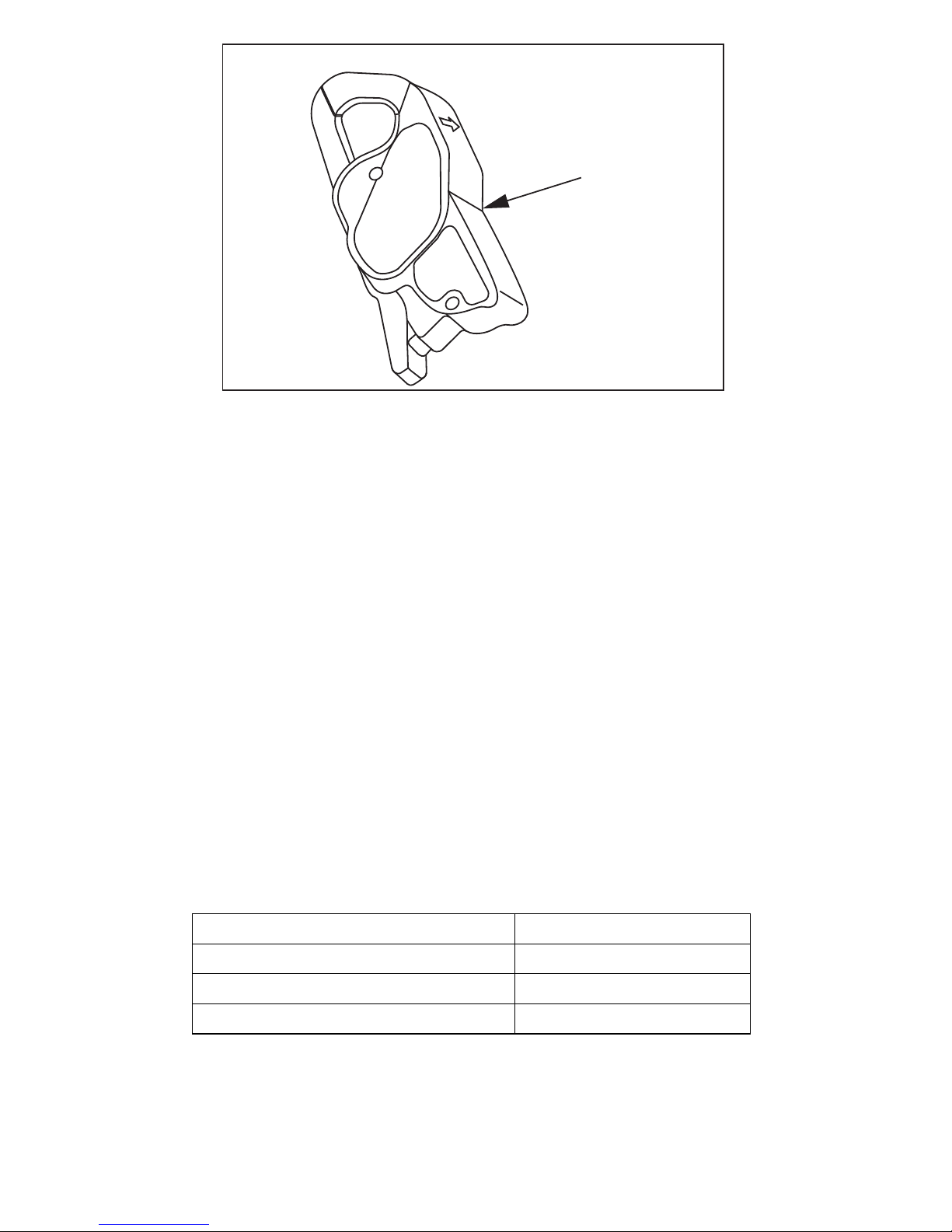
tactile barrier, see Figure 1.
Page 3
Tactile Barrier
Figure 1. 3005-PR AC Current Clamp
Operating Instructions
1. Connect the Clamp to the 1750 current input jack.
Verify that the 1750 has recognized that a current
Clamp is connected.
2. Place the Clamp around the conductor under test.
ezk01.eps
3. Observe and take measurements as required. Positive
output indicates that the current flow is in the direction
shown by the arrow on the Clamp.
Maintenance
Cleaning
Clean the Clamp periodically by wiping it with a damp cloth and
detergent. Do not use abrasive cleaners or solvents. Do not
immerse the Clamp in liquids.
Specifications
Electrical Specifications
Operating Range 5 A
Measurement Range 0.1 to 10 A
Transformation Ratio Voltage Output
Output Signal 400 mV/A (2 V @ 5 A)
Page 4
Range Accuracy Phase Shift
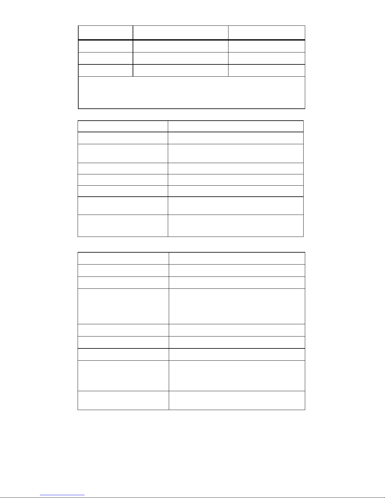
0.1 to 1 A ≤ 2 % of Reading ± 1 mV 1 to 5 A ≤ 1 % of Reading ± 1 mV ≤ 3 °
5 to 40 A ≤ 1 % of Reading ± 1 mV ≤ 2 °
Reference conditions: 20 °C to 26 °C, 20 to 75 % RH, external magnetic
field < 40 A/m, 48 to 65 Hz sine wave, distortion factor less than 1 %, no
dc component, no external current carrying conductor, test sample
centered. Load impedance 1 MΩ.
Overload 25 A Continuous
Frequency Range 40 to 10 kHz
Crest Factor 3 @ 10 A rms with an error (due to CF) of
3 %
Working Voltage 600 V rms
Common Mode Voltage 30 V rms
Influence of dc on ac signal dc current <20 A, < 5 %
Influence of Conductor
Position in Jaw
Influence of Frequency
0.5 % of mV output @ 50.60 Hz
40 to 1 kHz: 0.5 % of mV output
1 kHz to 10 kHz: 2 % or mV output
Mechanical Specifications
Dimensions 5.47 x 2.00 x 1.18 in. (139 x 51 x 30 mm)
Weight 6.5 oz (180 g)
Jaw Opening 0.83 in. (21 mm)
Maximum Conductor Size
Cable
Bus Bar
Case Protection IP 40 (IEC 60529)
Drop Test 1.0 m six sides to oak floor
Vibration MIL-PRF-28800F Class 2 random
Polycarbonate Material
Jaws
Case
0.78 in. (20 mm)
0.78 in. x 0.19 in. (20 x 5 mm)
Polycarbonate Red UL 94 V0
Polycarbonate ABS Gray: UL 94 V0
Output 1 ft round 2 conductor cable w/4-pin Lemo
connector
Page 5
Environmental Specifications
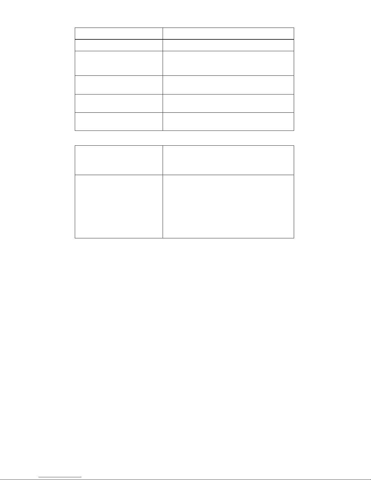
Operating Temperature 14 °F to 131 °F (−10 °C to +55 °C)
Storage Temperature −40 °F to 158 °F (−40 °C to +70 °C)
Altitude
Non-operating:
Operating:
Operating Relative
Humidity
Influence of Temperature ≤ 150 ppm/ °K, or 0.15 % of mV output per
Influence of Humidity ≤ 10 to 90 % RH: 0.2% of mV output per
0 to 12,000 m
0 to 2000 m
10 °C to 35 °C 85 % RH (without roll-off
above 35 °C)
10 °K
10 °K @ 18 °C to 28 °C
Safety Specifications
Electrical
Electromagnetic
Compatibility
Conforms to EN/IEC 61010 and 61010-2032
600 V Cat. III, Pollution Degree 2
EN 50081-1 Class B
EN 50082-2 Electrostatic discharge;
IEC 61000-4-2
Radiated field IEC 61000-4-3
Fast transients IEC 61000-4-4
Magnetic field at 50/60 Hz IEC 61000-4-8
Page 6

LIMITED WARRANTY AND LIMITATION OF LIABILITY
This Fluke product will be free from defects in material and
workmanship for one year from the date of purchase. This
warranty does not cover fuses, disposable batteries, or damage
from accident, neglect, misuse, alteration, contamination, or
abnormal conditions of operation or handling. Resellers are not
authorized to extend any other warranty on Fluke’s behalf. To
obtain service during the warranty period, contact your nearest
Fluke authorized service center to obtain return authorization
information, then send the product to that Service Center with a
description of the problem.
THIS WARRANTY IS YOUR ONLY REMEDY. NO OTHER
WARRANTIES, SUCH AS FITNESS FOR A PARTICULAR
PURPOSE, ARE EXPRESSED OR IMPLIED. FLUKE IS NOT
LIABLE FOR ANY SPECIAL, INDIRECT, INCIDENTAL OR
CONSEQUENTIAL DAMAGES OR LOSSES, ARISING FROM
ANY CAUSE OR THEORY. Since some states or countries do
not allow the exclusion or limitation of an implied warranty or of
incidental or consequential damages, this limitation of liability
may not apply to you.
Fluke Corporation
P.O. Box 9090
Everett, WA 98206-9090
U.S.A.
11/99
Fluke Europe B.V.
P.O. Box 1186
5602 BD Eindhoven
The Netherlands
 Loading...