

Page 1

®
291, 292, 294
100 MS/s Arbitrary Waveform Generators
Users Manual
March 2006
© 2006 Fluke Corporation, All rights reserved. Printed in USA
All product names are trademarks of their respective companies.
Find Quality Products Online at: [email protected]
www.GlobalTestSupply.com
Page 2

LIMITED WARRANTY AND LIMITATION OF LIABILITY
Each Fluke product is warranted to be free from defects in material and workmanship under normal use and
service. The warranty period is one year and begins on the date of shipment. Parts, product repairs, and
services are warranted for 90 days. This warranty extends only to the original buyer or end-user customer of
a Fluke authorized reseller, and does not apply to fuses, disposable batteries, or to any product which, in
Fluke's opinion, has been misused, altered, neglected, contaminated, or damaged by accident or abnormal
conditions of operation or handling. Fluke warrants that software will operate substantially in accordance
with its functional specifications for 90 days and that it has been properly recorded on non-defective media.
Fluke does not warrant that software will be error free or operate without interruption.
Fluke authorized resellers shall extend this warranty on
only but have no authority to extend a greater or different warranty on behalf of Fluke. Warranty support is
available only if product is purchased through a Fluke authorized sales outlet or Buyer has paid the
applicable international price. Fluke reserves the right to invoice Buyer for importation costs of
repair/replacement parts when product purchased in one country is submitted for repair in another country.
Fluke's warranty obligation is limited, at Fl
or replacement of a defective product which is returned to a Fluke authorized service center within the
warranty period.
To obtain warranty service, contact your nearest Fl
authorization information, then send the product to that service center, with a description of the difficulty,
postage and insurance prepaid (FOB Destination). Fluke assumes no risk for damage in transit. Following
warranty repair, the product will be returned to Buyer, transportation prepaid (FOB Destination). If Fluke
determines that failure was caused by neglect, misuse, contamination, alteration, accident, or abnormal
condition of operation or handling, including overvoltage failures caused by use outside the product’s
specified rating, or normal wear and tear of mechanical components, Fluke will provide an estimate of repair
costs and obtain authorization before commencing the work. Following repair, the product will be returned to
the Buyer transportation prepaid and the Buyer will be billed for the repair and return transportation charges
(FOB Shipping Point).
THIS WARRANTY IS BUYER'S SOLE AND EXCLUSIVE REMEDY AND IS IN LIEU OF ALL OTHER
WARRANTIES
OF MERCHANTABILITY OR FITNESS FOR A PARTICULAR PURPOSE. FLUKE SHALL NOT BE LIABLE
FOR ANY SPECIAL, INDIRECT, INCIDENTAL, OR CONSEQUENTIAL DAMAGES OR LOSSES,
INCLUDING LOSS OF DATA, ARISING FROM ANY CAUSE OR THEORY.
Since some countries or states do not allow limitation of the term of an implied
limitation of incidental or consequential damages, the limitations and exclusions of this warranty may not
apply to every buyer. If any provision of this Warranty is held invalid or unenforceable by a court or other
decision-maker of competent jurisdiction, such holding will not affect the validity or enforceability of any other
provision.
, EXPRESS OR IMPLIED, INCLUDING BUT NOT LIMITED TO ANY IMPLIED WARRANTY
uke's option, to refund of the purchase price, free of charge repair,
new and unused products to end-user customers
uke authorized service center to obtain return
warranty, or exclusion or
11/99
Find Quality Products Online at: [email protected]
www.GlobalTestSupply.com
Page 3
Safety
This generator is a Safety Class I instrument according to IEC classification and has been
designed to meet the requirements of EN61010-1:2001 (Safety Requirements for
Electrical Equipment for Measurement, Control and Laboratory Use). It is an Installation
Category II instrument intended for operation from a normal single phase supply.
This instrument has been tested in accordance with EN61010-1, CSA 22.2 No.
04 and UL 61010A-1 and has been supplied in a safe condition. This instruction manual
contains some information and warnings which have to be followed by the user to ensure
safe operation and to retain the instrument in a safe condition.
This instrument has been designed for indoor use in a
the temperature range 5 °C to 40 °C, 20 % - 80 % RH (non-condensing). It may
occasionally be subjected to temperatures between +5 °C and -10 °C without degradation
of its safety. Do not operate the instrument while condensation is present.
Use of this instrument in a manner not specified by these instructions may impair the
protection provided. Do not operate the instrument outside its rated supply
safety
voltages or environmental range.
Pollution Degree 2 environment in
61010-1-
Warning
To avoid the possibility of electric shock:
• This instrument must be earthed.
• An
• When the instrument is connected to its suppl
y interruption of the mains earth conductor inside or
outside the instrument will make the instrument
dangerous. Intentional interruption is prohibited. The
protective action must not be negated by the use of an
extension cord without a protective conductor.
y, terminals
may be live and opening the covers or removal of parts
(except those to which access can be gained by hand) is
likely to expose live parts.
• Disconnect the instrument from all voltage sources before
opening it for an
or repair.
• An
• Make sure that onl
If the instrument is clearly defective, has been subject to
mechanical damage, excessive m
the safety protection may be impaired and the apparatus should
be withdrawn from use and returned for checking and repair.
Find Quality Products Online at: [email protected]
y adjustment, maintenance and repair of the opened
instrument under voltage shall be avoided as far as
possible and, if inevitable, shall be carried out only by a
skilled person who is aware of the hazard involved.
and of the specified type are used for replacement. The use
of makeshift fuses and the short-circuiting of fuse holders
is prohibited.
www.GlobalTestSupply.com
y adjustment, replacement, maintenance
y fuses with the required rated current
Caution
oisture or chemical corrosion
i
Page 4
Note
This instrument uses a Lithium button cell for non-volatile memory
battery
back-up. Typical battery life is 5 years. In the event of replacement
becoming necessary, replace only with a cell of the correct type, a 3 V
Li/Mn0
20 mm button cell type 2032. Do not mix with solid waste stream.
2
Do not cut open, incinerate, expose to temperatures above 60 °C or attempt
to recharge. Used batteries should be disposed of by a qualified recycler or
hazardous materials handler. Contact your authorized Fluke Service
Center for recycling information.
Caution
Do not wet the instrument when cleaning it and in particular use
onl
y a soft dry cloth to clean the LCD window.
The following symbols are used on the instrument and in this manual:
Caution - refer to the accompanying documentation,
incorrect operation m
ay damage the instrument.
Mains supply OFF.
Mains supply ON.
Alternating current.
Warning - hazardous voltages may be present.
Conforms to European Union directives:
EN61010-1-2001, EN61326
Verified by MET to be in conformance with relevant US
and Canadian Standards:
CSA 22.2 No. 61010-1-04, UL 61010A-1
Do not mix with solid waste stream. Dispose using a
qualified recycler or hazardous material handler.
Protective Earth (Ground)
Find Quality Products Online at: [email protected]
www.GlobalTestSupply.com
ii
Page 5

EMC Compliance
This instrument meets the requirements of the EMC Directive 89/336/EEC.
Compliance was demonstrated by meeting the test li
Emissions
EN61326 (1998) EMC product standard for Electrical Equipment for Measurement,
Control and
a) Radiated: Class A
b) Conducted: Class B
c) Harmonics:
Immunity
EN61326 (1998) EMC product standard for Electrical Equipment for Measurement,
Control and
a) EN61000-4-2 (1995)
b) EN61000-4-3 (1997)
c) EN61000-4-11 (1994)
d) EN61000-4-4 (1995)
Laboratory Use. Test limits used were:
Laboratory Use. Test methods, limits and performance achieved were:
Electrostatic
Electro
Voltage Interrupt: 1 c
Fast Transien
and RS232/GPIB ports)
Discharge: 4 kV air, 4 kV contact
magnetic Field: 3 V/m, 80 % AM at 1 kHz
ycle, 100 %
t: 1 kV peak (ac line), 0.5 kV peak (signal lines
mits of the following standards:
EN61000-3-2 (2000) Class A;
the instrum
ent is Class A by product category.
Performance A.
Performance A.
Performance A.
Performance A.
e) EN61000-4-5 (1995)
Surge: 0.5
f) EN61000-4-6 (1996)
Conducted R
connections <3 m not tested)
According to EN61326 the definitions of performance criteria are:
Performance criterion A: ‘During test normal performance
Performance criterion B: ‘During test, temporary
Performance criterion C: ‘During test, temporary
To ensure continued compliance with the EMC directive the
follow
a) connect the generator to other equipment using only high
quality
kV (line to line), 1 kV (line to ground)
F: 3 V, 80 % AM at 1 kHz (AC line only; signal
within the specification
limits.’
degradation, or loss of function or
performance which is self-recovering’.
degradation, or loss of function or
performance which requires operator intervention or system
reset occurs.’
Cautions
ing precautions should be observed:
, double-screened cables.
Performance A.
Performance A.
Find Quality Products Online at: [email protected]
www.GlobalTestSupply.com
iii
Page 6

b) after opening the case for any reason ensure that all signal
and ground connections are remade correctl
the cover. Always ensure all case screws are correctly refitted
and tightened.
c) In the event of part replacement becoming necessary, only
use components of an identical ty
pe, see the Service Manual.
y before replacing
iv
Find Quality Products Online at: [email protected]
www.GlobalTestSupply.com
Page 7

Table of Contents
Chapter Title Page
Safety.................................................................................................... i
EMC Compliance .............................................................................................. iii
Emissions....................................................................................................... iii
Immunity ....................................................................................................... iii
1 Introduction and Specifications......................................................... 1-1
Introduction........................................................................................................ 1-2
Introduction........................................................................................................ 1-2
Specifications..................................................................................................... 1-4
Waveforms .................................................................................................... 1-4
Standard Waveforms................................................................................. 1-4
Arbitrary Waveforms................................................................................ 1-5
Sequence ................................................................................................... 1-5
Output Filter.............................................................................................. 1-5
Noise ......................................................................................................... 1-5
Operating modes............................................................................................ 1-6
Triggered Burst ......................................................................................... 1-6
Gated......................................................................................................... 1-6
Sweep........................................................................................................ 1-6
Tone Switching ......................................................................................... 1-7
Trigger Generator...................................................................................... 1-7
Outputs .......................................................................................................... 1-7
Main Output.............................................................................................. 1-7
Sync Output............................................................................................... 1-8
Auxiliary sine out...................................................................................... 1-8
System clock ............................................................................................. 1-8
Inputs............................................................................................................. 1-8
Trig In ....................................................................................................... 1-8
Modulation In............................................................................................ 1-8
Sum In....................................................................................................... 1-9
Hold........................................................................................................... 1-9
Ref Clock In/Out....................................................................................... 1-9
Arb Clock In/Out....................................................................................... 1-9
Inter-Channel Operation................................................................................ 1-9
v
Find Quality Products Online at: [email protected]
www.GlobalTestSupply.com
Page 8

291, 292, 294
Users Manual
Inter-Channel Modulation:........................................................................ 1-9
Inter-Channel Analog Summing:.............................................................. 1-10
Inter-Channel Synchronization: ................................................................ 1-10
Inter-Channel Triggering: ......................................................................... 1-10
Interfaces ....................................................................................................... 1-11
General .......................................................................................................... 1-11
2 Installation ........................................................................................... 2-1
AC Supply Voltage............................................................................................ 2-2
Fuse ............................................................................................................... 2-2
AC Supply Cable........................................................................................... 2-2
Mounting............................................................................................................ 2-2
Ventilation ......................................................................................................... 2-2
3 Connections......................................................................................... 3-1
Front panel connections..................................................................................... 3-2
MAIN OUT................................................................................................... 3-2
SYNC OUT................................................................................................... 3-2
TRIG IN ........................................................................................................ 3-3
SUM IN......................................................................................................... 3-3
MODULATION............................................................................................ 3-3
Rear Panel Connections..................................................................................... 3-3
REF CLOCK IN/OUT................................................................................... 3-3
HOLD IN....................................................................................................... 3-3
ARB CLOCK IN/OUT.................................................................................. 3-4
MAIN OUT................................................................................................... 3-4
RS232............................................................................................................ 3-4
GPIB (IEEE-488) .......................................................................................... 3-5
USB ............................................................................................................... 3-5
MEMORY CARD......................................................................................... 3-5
4 Initial Operation................................................................................... 4-1
Introduction........................................................................................................ 4-2
Initial Operation................................................................................................. 4-2
Switching On................................................................................................. 4-2
Display Contrast............................................................................................ 4-2
Keyboard ....................................................................................................... 4-2
Principles of Editing .......................................................................................... 4-3
Principles of Operation...................................................................................... 4-5
Clock Synthesis Mode................................................................................... 4-5
DDS Mode..................................................................................................... 4-6
5 Standard Waveforms .......................................................................... 5-1
Introduction........................................................................................................ 5-2
Standard Waveform Operation.......................................................................... 5-2
Setting Generator Parameters ............................................................................ 5-2
Waveform Selection...................................................................................... 5-2
Frequency...................................................................................................... 5-2
Amplitude...................................................................................................... 5-3
DC Offset ...................................................................................................... 5-4
Warning and Error Messages............................................................................. 5-5
Synchronization Output..................................................................................... 5-6
vi
Find Quality Products Online at: [email protected]
www.GlobalTestSupply.com
Page 9

6 Sweep Operation................................................................................. 6-1
General............................................................................................................... 6-2
Principles of Sweep Operation...................................................................... 6-2
Connections for Sweep Operation................................................................. 6-2
Setting sweep parameters................................................................................... 6-2
Sweep Range................................................................................................. 6-3
Sweep Time................................................................................................... 6-3
Sweep Type................................................................................................... 6-4
Sweep Spacing............................................................................................... 6-5
Sweep Marker................................................................................................ 6-5
Sweep Hold ................................................................................................... 6-5
7 Triggered Burst and Gate................................................................... 7-1
General............................................................................................................... 7-2
Internal Trigger Generator............................................................................. 7-2
External Trigger Input................................................................................... 7-2
Adjacent Channel Trigger Output ................................................................. 7-3
Triggered Burst.................................................................................................. 7-3
Trigger Source............................................................................................... 7-4
Trigger Edge.................................................................................................. 7-4
Burst Count.................................................................................................... 7-4
Start Phase..................................................................................................... 7-5
Manual Initialization of Inter-Channel Triggering........................................ 7-5
Gated mode........................................................................................................ 7-6
Gate Source ................................................................................................... 7-6
Gate Polarity.................................................................................................. 7-6
Start Phase..................................................................................................... 7-6
Sync Out in Triggered Burst and Gated Modes................................................. 7-7
Contents (continued)
8 Tone Mode ........................................................................................... 8-1
Introduction........................................................................................................ 8-2
Tone Frequency............................................................................................. 8-2
Tone Type...................................................................................................... 8-2
Tone Switching Source.................................................................................. 8-3
DTMF Testing With Two Sources................................................................ 8-3
9 Arbitrary Waveform Generation......................................................... 9-1
Introduction........................................................................................................ 9-2
Arbitrary Waveform Terms........................................................................... 9-2
Principles of Arbitrary Waveform Creation and Modification...................... 9-2
Selecting and Outputting Arbitrary Waveforms................................................ 9-3
Creating New Waveforms............................................................................. 9-4
Create Blank Waveform............................................................................ 9-4
Create Waveform Copy............................................................................. 9-4
Modifying Arbitrary Waveforms................................................................... 9-5
Resize Waveform...................................................................................... 9-5
Rename Waveform.................................................................................... 9-6
Waveform Info.......................................................................................... 9-6
Delete Waveform...................................................................................... 9-6
Edit Waveform.......................................................................................... 9-7
Point Edit................................................................................................... 9-7
Line Edit.................................................................................................... 9-7
Wave Insert ............................................................................................... 9-8
vii
Find Quality Products Online at: [email protected]
www.GlobalTestSupply.com
Page 10

291, 292, 294
Users Manual
Block Copy ............................................................................................... 9-8
Waveform Amplitude................................................................................ 9-9
Waveform Offset....................................................................................... 9-10
Wave Invert............................................................................................... 9-10
Position Markers ....................................................................................... 9-10
Arbitrary Waveform Sequence.......................................................................... 9-11
Sequence Set-Up ........................................................................................... 9-12
Frequency and Amplitude Control with Arbitrary Waveforms......................... 9-13
Frequency...................................................................................................... 9-13
Amplitude...................................................................................................... 9-15
Sync Out Settings with Arbitrary Waveforms................................................... 9-15
Waveform Hold in Arbitrary Mode................................................................... 9-15
Output Filter Setting .......................................................................................... 9-16
10 Pulse and Pulse-trains........................................................................ 10-1
Introduction........................................................................................................ 10-2
Pulse Set-Up ...................................................................................................... 10-2
Pulse-Train Set-Up ............................................................................................ 10-4
Waveform Hold in Pulse and Pulse-Train Modes ............................................. 10-8
11 Modulation ........................................................................................... 11-1
Introduction........................................................................................................ 11-2
External VCA................................................................................................ 11-2
External SCM................................................................................................ 11-3
Internal Modulation ........................................................................................... 11-3
12 Sum....................................................................................................... 12-1
Introduction........................................................................................................ 12-2
External Sum...................................................................................................... 12-2
Internal Sum....................................................................................................... 12-3
13 Synchronizing...................................................................................... 13-1
Introduction........................................................................................................ 13-2
Inter-Channel Synchronization.......................................................................... 13-2
Synchronizing Principles............................................................................... 13-2
Master-Slave Allocation................................................................................ 13-2
Phase-Setting Between Channels .................................................................. 13-4
Other Synchronizing Considerations............................................................. 13-4
Synchronizing two generators............................................................................ 13-5
Connections for Synchronization .................................................................. 13-6
Generator Set-Ups......................................................................................... 13-6
Synchronizing................................................................................................ 13-7
14 Memory Card ....................................................................................... 14-1
Introduction........................................................................................................ 14-2
Card Sizes and Formats ..................................................................................... 14-2
Formatting.......................................................................................................... 14-3
Saving Files to a Memory Card......................................................................... 14-3
Avoiding Long Filenames............................................................................. 14-3
Storing and Recalling Set-Ups........................................................................... 14-3
Sorting Files....................................................................................................... 14-5
viii
Find Quality Products Online at: [email protected]
www.GlobalTestSupply.com
Page 11

15 System Operations from the Utility Menu......................................... 15-1
Introduction........................................................................................................ 15-2
Channel Waveform Information........................................................................ 15-2
Warnings and Error Messages........................................................................... 15-2
Remote Interface Set-Up.................................................................................... 15-2
SYS/REF Clock In/Out and System Clock Setting ........................................... 15-2
Power On Setting............................................................................................... 15-3
System Information............................................................................................ 15-3
Calibration ......................................................................................................... 15-4
Copying Channel Set-Ups ................................................................................. 15-4
16 Calibration............................................................................................ 16-1
Introduction........................................................................................................ 16-2
Equipment Required.......................................................................................... 16-2
Calibration Procedure ........................................................................................ 16-2
Setting the Password...................................................................................... 16-2
Password Access to Calibration .................................................................... 16-3
Changing the Password ................................................................................. 16-3
Calibration Routine............................................................................................ 16-3
Remote Calibration............................................................................................ 16-6
Contents (continued)
17 Remote Operation ............................................................................... 17-1
Introduction........................................................................................................ 17-2
Address and Baud Rate Selection...................................................................... 17-2
Remote/Local Operation.................................................................................... 17-2
RS232 interface.................................................................................................. 17-3
Single Instrument RS232 Connections.......................................................... 17-3
Addressable RS232 Connections................................................................... 17-3
RS232 Character Set...................................................................................... 17-4
Addressable RS232 Interface Control Codes................................................ 17-4
Full List of Addressable RS232 Interface Control Codes............................. 17-6
USB Interface .................................................................................................... 17-6
GPIB Interface................................................................................................... 17-6
GPIB Subsets................................................................................................. 17-7
GPIB IEEE Std. 488.2 Error Handling.......................................................... 17-7
GPIB Parallel Poll ......................................................................................... 17-7
Status Reporting................................................................................................. 17-8
Standard Event Status and Standard Event Status Enable Registers............. 17-8
Status Byte Register and Service Request Enable Register........................... 17-9
Power-On Settings......................................................................................... 17-10
Remote commands............................................................................................. 17-10
RS232 Remote Command Formats............................................................... 17-10
GPIB Remote Command Formats................................................................. 17-11
Command List............................................................................................... 17-11
Channel Selection...................................................................................... 17-12
Frequency and Period................................................................................ 17-12
Amplitude and DC Offset ......................................................................... 17-12
Waveform Selection.................................................................................. 17-13
Arbitrary Waveform Create and Delete.................................................... 17-13
Arbitrary Waveform Editing..................................................................... 17-15
Waveform Sequence Control.................................................................... 17-17
Mode Commands...................................................................................... 17-18
Input/Output Control................................................................................. 17-18
ix
Find Quality Products Online at: [email protected]
www.GlobalTestSupply.com
Page 12

291, 292, 294
Users Manual
Modulation Commands............................................................................. 17-19
Synchronizing Commands ........................................................................ 17-19
Status Commands...................................................................................... 17-19
Miscellaneous Commands ........................................................................ 17-21
Remote Command Summary............................................................................. 17-22
18 Maintenance......................................................................................... 18-1
Introduction........................................................................................................ 18-2
Cleaning............................................................................................................. 18-2
Appendices
A AC Supply Voltage ..................................................................................... A-1
B Warning and Error Messages...................................................................... B-1
C SYNC OUT Automatic Settings ................................................................. C-1
D Factory System Defaults ............................................................................. D-1
E Waveform Manager Plus............................................................................. E-1
F Block Diagrams........................................................................................... F-1
G Front and Rear Panel Drawings................................................................... G-1
List of Figures
Figure Title Page
4-1. Single-Channel Simplified Block Diagram............................................................ 4-6
4-2. Clock Synthesis Mode............................................................................................ 4-6
4-3. Direct Digital Synthesis Mode............................................................................... 4-7
8-1. Tone Waveform Types........................................................................................... 8-3
17-1. Single Instrument RS232 Connections .................................................................. 17-3
17-2. RS232 Daisy-Chained Instruments ........................................................................ 17-3
17-3. RS232 Daisy-Chain Connector Wiring.................................................................. 17-4
17-4. Status Model........................................................................................................... 17-9
1-1. Mains transformer connections.............................................................................. 1-2
F-1. Block Diagram: Single Channel............................................................................. F-1
F-2. Inter-Channel Block Diagram ................................................................................ F-2
G-1. Model 291 Front Panel........................................................................................... G-1
G-2. Model 292 Front Panel........................................................................................... G-2
G-3. Model 294 Front Panel........................................................................................... G-2
G-4. Model 291 Rear Panel............................................................................................ G-2
G-5. Model 294 Rear Panel............................................................................................ G-3
x
Find Quality Products Online at: [email protected]
www.GlobalTestSupply.com
Page 13

Chapter 1
Introduction and Specifications
Title Page
Introduction........................................................................................................ 1-2
Specifications..................................................................................................... 1-4
Waveforms .................................................................................................... 1-4
Standard Waveforms................................................................................. 1-4
Arbitrary Waveforms................................................................................ 1-5
Sequence ................................................................................................... 1-5
Output Filter.............................................................................................. 1-5
Noise ......................................................................................................... 1-5
Operating modes............................................................................................ 1-6
Triggered Burst ......................................................................................... 1-6
Gated......................................................................................................... 1-6
Sweep........................................................................................................ 1-6
Tone Switching ......................................................................................... 1-7
Trigger Generator...................................................................................... 1-7
Outputs .......................................................................................................... 1-7
Main Output.............................................................................................. 1-7
Sync Output............................................................................................... 1-8
Auxiliary sine out...................................................................................... 1-8
System clock ............................................................................................. 1-8
Inputs............................................................................................................. 1-8
Trig In ....................................................................................................... 1-8
Modulation In............................................................................................ 1-8
Sum In....................................................................................................... 1-9
Hold........................................................................................................... 1-9
Ref Clock In/Out....................................................................................... 1-9
Arb Clock In/Out....................................................................................... 1-9
Inter-Channel Operation................................................................................ 1-9
Inter-Channel Modulation:........................................................................ 1-9
Inter-Channel Analog Summing:.............................................................. 1-10
Inter-Channel Synchronization: ................................................................ 1-10
Inter-Channel Triggering: ......................................................................... 1-10
Interfaces ....................................................................................................... 1-11
General .......................................................................................................... 1-11
1-1
Find Quality Products Online at: [email protected]
www.GlobalTestSupply.com
Page 14

291, 292, 294
Users Manual
Introduction
This range of synthesized programmable arbitrary waveform generators have the
following features:
• 1, 2
• Additional D
• Up to 1
• Sinewaves up to 40
• Output level
• 1 M poi
• Co
• Waveform
• Inter-channel triggering, summing,
• GPIB, RS232
The instruments use a combination of direct digital synthesis and variable clock
techniques to
They can generate a wide variety of waveforms between 0·1 mHz and 50 MHz with high
resolution and accuracy.
or 4 independent arb channels
C to 50MHz fixed amplitude sine and squarewave outputs on 2- and
4-channel instruments
00 MHz sampling frequency
MHz, squarewaves up to 50 MHz
2.5 mV to 10 V p-p into 50 Ω with 12 bit vertical resolution
nts horizontal resolution per channel
mpact Flash card for non-volatile waveform memory
linking, looping and sequencing
modulation and phase control
and USB interfaces
provide high performance and extensive facilities in a compact package.
Arbitrary waveforms may be defined with 12
1,048,576 horizontal points. In addition a number of standard waveforms are available
including sine, square, triangle, ramp and pulse.
Arbitrary waveforms may be replayed at a user specified waveform frequency
or the sample rate may be defined in terms of period or frequency. Alternatively, an
external arb clock may be used at frequencies up to 50 MHz.
Extensive waveform editing features between defined start and end points are
incorporated,
invert. More comprehensive features are available using the arbitrary waveform creation
software supplied. This is a powerful Windows-based design tool that enables the user to
create waveforms from mathematical expressions, from combinations of other
waveforms, freehand, or using a combination of all three techniques. Waveforms created
in this way can be downloaded via the RS232, GPIB or USB interfaces, or they can be
transferred to the generator on a removable memory card, written to by the PC using the
USB-connected card reader/writer provided.
Up to 500 different waveforms may be stored with the length and name specified by the
user; the total size of all the wavefor
card. Waveforms may be linked together to form a sequence of up to 1024 steps. Each
waveform may have a user defined repeat count from 1 to 32,768.
including waveform insert, point edit, line draw, amplitude adjust and
ms stored is limited only by the size of the memory
bit vertical resolution and from 8 to
or period,
1-2
Find Quality Products Online at: [email protected]
www.GlobalTestSupply.com
Page 15

Introduction and Specifications
All waveforms can be swept over their full frequency range at a rate variable between
1 millisecond and 15 minutes. Sweep can be linear or logarithmic, single or continuous.
Single sweeps can be triggered from the front panel, the trigger input, or the digital
interfaces. A sweep marker is provided.
Introduction 1
Amplitude modulation is available for all waveform
channel or from an external generator via the MODULATION input socket.
Signal summing is available for all waveforms and is controlled fro
channel or from an external generator via the SUM input socket.
All waveforms are available as a triggered burst, whereby each active edge of the trigger
signal will produce one burst of the carrier. The number of cy
between 1 and 1,048,575. The gated mode turns the output signal on when the gating
signal is true and off when it is false. Both triggered and gated modes can be operated
from the previous or next channel, from the internal trigger generator (0.005 Hz to
100 kHz), from an external source (dc to 1 MHz) or by a key press or remote command.
Any number of channels can be synchronized with user defined phase angle bet
channels. This can be used to generate multi-phase waveforms or synchronized
waveforms of different frequencies.
The signals from the REF IN/OUT socket and the SYNC OUT socket can be used to
nchronize two instruments where more than 4 channels are required.
sy
The generator parameters are clearly display
20 characters. Soft-keys and sub menus are used to guide the user through even the most
complex functions.
All parameters can be entered directly from the nu
parameters can be incremented or decremented using the rotary control. This system
combines quick and easy numeric data entry with quasi-analogue adjustment when
required.
ed on a backlit LCD with 4 rows of
s and is controlled from the previous
m the previous
cles in the burst can be set
ween
meric keypad. Alternatively most
The generator has RS232, GPIB and USB interfaces as standard which can be used for
rem
ote control of all of the instrument functions or for the down-loading of arbitrary
waveforms. As well as operating in conventional RS232 mode the serial interface can
also be used in addressable mode whereby up to 32 instruments can be linked to a single
PC serial port.
1-3
Find Quality Products Online at: [email protected]
www.GlobalTestSupply.com
Page 16

291, 292, 294
Users Manual
Specifications
Waveforms
Standard Waveforms
Sine, Cosine, Haversine, Havercosine
Specifications apply at 18 to 28 ºC after 30 minutes warm-up, at maximum output into
50 Ω.
Sine, square, triangle, DC, positive ramp, negative ramp, sin(x)/x, pulse, pulse train,
cosine, haversine and havercosine.
Range: 0·1 mHz to 40 MHz
Resolution: 0·1 mHz or 10 digits
Accuracy: 10 ppm for 1 year
Temperature stability: Typically <1 ppm/ºC.
Output level: 2.5 mV to 10 V p-p into 50 Ω
Harmonic distortion: <0.15 % THD to 100 kHz;
<-60 dBc to 2
<-50 dBc to 1 MHz,
<-40 dBc to 10 MHz
<-30 dBc to 40 MHz
Non-harmonic spurious: <-60 dBc to 1 MHz,
<-60 dBc +6 dB/octave 1 MHz to 40 M
0 kHz
Hz
Square
Range: 1 mHz to 50 MHz
Resolution: 1 mHz or 8 digits
Accuracy: 10 ppm for 1 year
Output level: 2.5 mV to 10V p-p into 50 Ω
Rise and fall times: <8 ns
Triangle
Range: 0.1 mHz to 500 kHz
Resolution: 0.1 mHz or 10 digits
Accuracy: 10 ppm for 1 year
Output level: 2.5 mV to 10V p-p into 50 Ω
Linearity error: <0.1 % to 30 kHz
Ramps and sin(x)/x
Range: 0.1 mHz to 500 kHz
Resolution: 0.1 mHz (10 digits)
Accuracy: 10 ppm for 1 year
Output level: 2.5 mV to 10V p-p into 50 Ω
Linearity error: <0.1 % to 30 kHz
1-4
Find Quality Products Online at: [email protected]
www.GlobalTestSupply.com
Page 17

Introduction and Specifications
Pulse and Pulse Train
Output level: 2.5 mV to 10V p-p into 50 Ω
Rise and fall times: <8 ns
Period:
range:
resolution:
accura
Delay:
range:
resolution:
cy:
40 ns to
8 digits
10 ppm for 1 year
−
0·001 % of period or 10 ns, whichever is greater (8 digits)
100 s
99·99 s to +99·99 s
Specifications 1
Width:
range:
resolution:
Note that the pulse width and absolute value of the delay
at any time.
Pulse trains of up to 10 pulses may be specified, ea
width, delay and level. The baseline voltage is separately defined and the sequence
repetition rate is set by the pulse train period.
Arbitrary Waveforms
Up to 500 user defined waveforms may be stored on the removable memory card.
Waveform
data via RS232, GPIB or USB, or by writing directly to the removable memory card
using the USB card reader/writer connected to a PC.
Waveform memory size: 1 M points per channel.
Vertical resolution: 12 bits
Sample clock range:
resolution:
accura
Sequence
Up to 1024 waveforms may be linked. Each waveform
32,768.
s can be defined by front panel editing controls, by downloading of waveform
cy:
10 ns to
0·001 % of period or 10 ns, whichever is greater (8 digits)
Minim
100 mHz to 100 MHz
8 digits
10 p
99·99 s
may not exceed the pulse period
ch pulse having independently defined
um waveform size is 8 points
pm for 1 year
can have a loop count of up to
A sequence of waveforms can be looped up to
Output Filter
Selectable between 40 MHz elliptic, 20 MHz Bessel or none.
Noise
Digital noise generated by a 35-bit linear feedback register clocked at 100 MHz. User’s
external filter defines bandwidth and response.
1-5
Find Quality Products Online at: [email protected]
www.GlobalTestSupply.com
1,048,575 times or run continuously.
Page 18

291, 292, 294
Users Manual
Operating modes
Triggered Burst
Gated
Each active edge of the trigger signal will produce one burst of the waveform.
Carrier waveforms: All standard and arbitrary
Maximum carrier frequency: The smaller of 2.5 MHz or
the maximum for the
selected waveform. 100 Msamples/s for arb or sequence.
Number of cycles: 1 to 1,048,575
Trigger repetition rate: 0.005 Hz to 100 kHz internal, dc to 1 MHz external.
Trigger signal source: Internal from
keyboard or trigger generator.
External from TRIG IN or remote interface.
Trigger start/stop phase: ±360 °, settable with 0.1 ° resolution, subject to
waveform
Waveform runs while the gate signal is true and stops
frequency and type.
while false.
Carrier waveforms: All standard and arbitrary.
Maximum carrier frequency: The smaller of 2.5 MHz or
the maximum for the
selected waveform. 100 Msamples/s for arb or sequence.
Trigger repetition rate: 0.005 Hz to 100 kHz internal, dc to 1 MHz external.
Gate signal source: Internal from keyboard, previous channel, next channel
or trigger gen
erator.
External from TRIG IN or remote interface.
Gate start/stop phase: ±360 °, settable with 0.1 ° resolution, subject to
waveform
frequency and type.
Sweep
Frequency sweep capability is provided for bot
h standard and arbitrary waveforms.
Arbitrary waveforms are expanded or condensed to exactly 4096 points and DDS
techniques are used to perform the sweep.
Carrier waveforms: All standard and arbitrary except pulse, pulse train and
sequence.
Sweep mode: Linear or logarithm
ic, triggered or continuous.
Sweep direction: Up, down, up/down or down/up.
Sweep range: From 1 mHz to 40 MHz in one range. Phase continuous.
Independent s
etting of the start and stop frequency.
Sweep time: 1 ms to 999 s (3 digit resolution).
Marker: Variable during sweep.
Sweep trigger source: The sweep may be free run or triggered from the
following sources:
manually from keyboard, externally
from TRIG IN input or remote interface.
Sweep hold: Sweep can be held and restarted by the HOLD key.
1-6
Find Quality Products Online at: [email protected]
www.GlobalTestSupply.com
Page 19

Introduction and Specifications
Specifications 1
Multi channel sweep Any number of channels may be swept simultaneously
with independent sweep parameters for each channel.
Amplitude, Offset and Waveform can be set
independently for each channel.
Tone Switching
Capability provided for both standard and arbitrar
y waveforms. Arbitrary waveforms are
expanded or condensed to exactly 4096 points and DDS techniques are used to allow
instantaneous frequency switching.
Carrier waveforms: All waveforms except pulse, pulse train and sequence.
Frequency list: Up to 16 frequencies from 1 mHz to 40 MHz.
Trigger repetition rate: 0.005 Hz to 100 kHz internal; dc to 1 MHz external.
Usable repetit
ion rate and waveform frequency depend
on the tone switching mode.
Source: Internal from keyboard, previous channel, next channel
or trigger gen
erator.
External from TRIG IN or remote interface.
Tone switching modes:
gated The tone is output while th
e trigger signal is true and
stopped, at the end of the current waveform cycle, while
the trigger signal is false. The next tone is output when
the trigger signal is true again.
triggered The tone is output when the trigger signal goes true and
the next tone
is output, at the end of the current
waveform cycle, when the trigger signal goes true again.
FSK The tone is output when the trigger signal goes true and
the next tone
is output, immediately, when the trigger
signal goes true again.
Using two channels or two instruments with their out
puts summed together it is possible
to generate DTMF (dual tone multi-frequency) test signals.
Trigger Generator
Internal source 0.005 Hz to 100 kHz square wave
adjustable in 10 µs steps. 3 digit
resolution. Available for external use from any SYNC OUT socket.
Outputs
Main Output - one for each channel
Output impedance: 50 Ω
Amplitude: 5 mV to 20 V p-p open circuit (2.5 mV to 10V p-p into
50 Ω). Am
plitude can be specified open circuit (hi Z) or
into an assumed load of 50 Ω or 600 Ω in V p-p, Vrms
or dBm.
Amplitude accuracy: 2 % ±1 mV at 1 kHz into 50 Ω.
Amplitude flatness: ±0.2 dB to 1 MHz; ±0.4 dB to 40 MHz
DC offset range: ±10 V.
DC offset plus signal peak lim
ited to ±10 V from 50 Ω.
DC offset accuracy: Typically 3 % ±10 mV, unattenuated.
1-7
Find Quality Products Online at: [email protected]
www.GlobalTestSupply.com
Page 20

291, 292, 294
Users Manual
Resolution: 3 digits or 1 mV for both amplitude and dc offset.
Sync Output - one for each channel
Multifunction output user definable or automatically selected to be any of the following:
Waveform sync (all
wavefor
ms):
A square wave with 50 % duty cycle at the main
waveform frequency, or a pulse coincident with the first
few points of an arbitrary waveform.
Position markers (arbitrary
onl
y):
Any point(s) on the waveform may have associated
marker bit(s) set high or low.
Burst done: Produces a pulse coincident with the last cycle of a burst.
Sequence sync: Produces a pulse coincident with the end of a waveform
sequence.
Trigger: Selects the current trigger signal. Useful for
sy
Sweep sync: Outputs a trigger signal at the start of sweep to
sy
additionally output a sweep marker.
Phase lock out: Used to synchronize two generators. Produces a positive
edge at the 0
Output signal level: Logic levels of <0.8 V and >3 V, except for sweep sync.
Sweep sy
high for the duration of the last frequency step at end of
sweep, with a narrow 1 V pulses at each marker point.
nchronizing burst or gated signals.
nchronize an oscilloscope or recorder. Can
° phase point.
nc is a 3-level waveform: low at start of sweep,
Auxiliary sine out
Frequency range: DC to 50 MHz, set by system clock
Output signal level: 1 V p-p into 50 Ω
System clock
Frequency range:: DC to 50 MHz, 0.1 Hz resolution
Inputs
Trig In
Frequency range: DC to 1 MHz.
Signal range: Threshold level adjustable ±5 V; maximum input ±10 V
Minimum pulse width: 50 ns for trigger and gate modes; 50 µs for Sweep mode.
Polarity: Selectable as high/rising edge or low/falling edge.
Input impedance: 10 kΩ
Modulation In
Frequency range: DC to 100 kHz.
Signal range: VCA: Approximately 1 V
p-p for 100 % level change at
maximum output; maximum input ±10 V.
SCM: Approximately ±1 V peak for maximum output.
1-8
Find Quality Products Online at: [email protected]
www.GlobalTestSupply.com
Page 21

Introduction and Specifications
Input impedance: Typically 1 kΩ.
Sum In
Frequency range: DC to 30 MHz (25 MHz on
Signal range: Approximately 2 V p-p input for 20 V p-p output;
Input impedance: Typically 1 kΩ.
Hold
Holds an arbitrary waveform at its current position. A
causes the waveform to stop at the current position and wait until a TTL high level or
switch opening which allows the waveform to continue. The front panel MAN HOLD
key or remote command may also be used to control the hold function. The HOLD input
be enabled independently for each channel.
may
Input impedance: 10 kΩ
Maximum input: ±10 V.
Ref Clock In/Out
Set to input: Input for an external 10 MHz reference clock.
Set to output: Buffered version of the internal 10 MHz clock. Output
Set to phase lock: Used together with SYNC OUT on a master and
Maximum input: +5 V, -1 V
2- and 4-channel
instruments)
maxim
TTL/CMOS threshold level.
levels nom
TRIG IN on a slave to synchronize (phase lock) two
separat
um input ±10 V.
TTL low level or switch closure
inally 1 V and 4 V from 50 Ω.
e generators.
Specifications 1
Arb Clock In/Out
Set to input: Input for external arb clock.
Set to output: Outputs system clock;
Frequency range: DC to 50 MHz
Maximum input voltage: +5 V, -1 V
Inter-Channel Operation
Inter-Channel Modulation:
The waveform from any channel may be used to amplitude modulate (AM) or suppressed
carrier
modulated (AM or SCM) with the signal at the MODULATION input socket.
Carrier frequency: Entire range for selected waveform.
Carrier waveforms: All standard and arbitrary waveforms.
Modulation types:
AM
SCM
modulate (SCM) the next channel. Alternatively any number of channels may be
TTL/CMOS threshold level.
logic levels <0.8 V and >3
Double sideband with carrier.
Double sideband suppressed carrier.
V.
1-9
Find Quality Products Online at: [email protected]
www.GlobalTestSupply.com
Page 22

291, 292, 294
Users Manual
Inter-Channel Analog Summing:
Modulation source: Internal from the previous channel;
external from modulation input socket.
The external modulation signal may be applied to any
number of channels simultaneously.
Frequency range: DC to >100 kHz.
Internal AM:
depth:
resolution:
0 %
to 105 %
1 %.
Carrier suppression (SCM): >40 dB.
External modulation signal
range: VCA:
S
CM:
Waveform summing sums the waveform from any
Approxim
ately 1 V p-p for 100 % level change at
maximum output.
Approximately ±1 V pk for maximum output.
channel into the next channel.
Alternatively any number of channels may be summed with the signal at the SUM input
socket.
Carrier frequency: Entire range for selected waveform.
Carrier waveforms: All standard and arbitrary waveforms.
Sum source: Internal from the previous channel;
Frequency r
ange: DC to >25 MHz.
External signal range: Approximately 5 V p-p input for 20 V p-p output.
Inter-Channel Synchronization:
Two or more channels may be synchroni
be assigned a phase angle relative to the other locked channels. Arbitrary waveforms and
waveform sequences may be synchronized but certain constraints apply to waveform
lengths and clock frequency ratios. With one channel assigned as the master and other
channels as slaves a frequency change on the master will be repeated on each slave thus
allowing easy generation of multi-phase waveforms at the same frequency.
Channels may be clocked using the master channel, the sy
clock.
Phase resolution:
DDS
waveforms:
non-DDS waveforms:
Phase error:
all
waveforms:
The signals from the REF IN/OUT socket and the SYNC OUT socket can be used to
phase lock two instrum
ents where more than four channels are required.
external fro
m SUM IN socket.
zed together. Each synchronized channel may
stem clock or an external arb
0.1 degree
0.1 degree or
360 degrees divided by the number of
points, whichever is the greater.
<±6 ns (internal clock),
<±5 ns (external arb or system clock)
Inter-Channel Triggering:
Any channel can be triggered by the previous or next channel.
1-10
Find Quality Products Online at: [email protected]
www.GlobalTestSupply.com
Page 23

Introduction and Specifications
The previous/next connections can be used to daisy chain a trigger signal from a start
channel, through a number of channels in the chain to an end channel. Each channel
receives the trigger out signal from the previous (or next) channel, and drives its selected
trigger out to the next (or previous) channel. The end channel trigger out can be set up to
drive the start channel, thus closing the loop.
Specifications 1
In this way, complex and versatile inter-channel trigger schemes
channel can have its trigger out and its output waveform set up independently. Trigger
out may be selected from Waveform End, Position Markers,
Sequence Sync or Burst Done.
Interfaces
Full remote control facilities are available through the
RS232: Variable Baud rate, 38,400 Baud maximum
IEEE−
USB 1.1
General
Display: 20 character x 4 row alphanumeric LCD.
Data entry: Keyboard selection of mode, waveform etc.; value entry direct
Memory card: Removable memory card conforming to the Compact Flash
Stored settings: Up to 500 complete instrument set-ups
Size: 3U (130 mm) high;
Weight: 4.1 kg (9 lb) (single channel),
Power: 220-240 V nominal 50/60Hz;
Operating Range: +5 °C to 40 °C, 20 to 80 % RH.
Storage Range: −20 °C to + 60 °C
Environmental: Indoor use at altitudes up to 2000 m, Pollution Degree 2.
Options: 19 inch rack mounting kit.
Safety: Complies with EN61010−
EMC: Complies with EN61326
may be set up. Each
RS232, USB or GPIB interfaces.
488: Conforms with IEEE488.1 and IEEE488.2
numeric keys or by rotary control.
by
mory card standard. Sizes from 32 MB to 1 GB can be used.
me
may be stored and
recalled from the memory card. Up to 500 arbitrary waveforms
can also be stored, independently of the instrument settings.
212 mm
350 mm wide (2- and 4-channel);
335 mm deep.
7.2 k
110-1
nominal voltage adjustable internally;
operating range ±10 % of nominal;
60 VA max (single channel),
100 VA max (2-channel),
150 VA max (4-channel).
Installation Category II.
UL 61010A-1
(½ rack) wide (single channel),
g (16 lb) (2- and 4-channel).
20 V or 100 V nominal 50/60/400 Hz;
1, CSA 22.2 No. 61010-1-04 and
. 9-pin D-connector.
1-11
Find Quality Products Online at: [email protected]
www.GlobalTestSupply.com
Page 24

Chapter 2
Installation
Title Page
AC Supply Voltage............................................................................................ 2-2
Fuse ............................................................................................................... 2-2
AC Supply Cable........................................................................................... 2-2
Mounting............................................................................................................ 2-2
Ventilation ......................................................................................................... 2-2
2-1
Find Quality Products Online at: [email protected]
www.GlobalTestSupply.com
Page 25

291, 292, 294
Users Manual
AC Supply Voltage
Fuse
AC Supply Cable
Check that the instrument operating voltage marked on the rear panel is correct for the
local supply. If it is necessary to change the operating voltage, follow the procedure
described in Appendix A.
Ensure that the correct mains fuse is fitted for the set operating voltage. The correct
mains fuse types are listed in Appendix A, together with instructions for fuse
replacement.
Warning
To avoid the possibility of electric shock, this instrument must
be earthed. Any interruption of the mains earth conductor
inside or outside the instrument will make the instrument
dangerous. Intentional interruption is prohibited. The
protective action must not be negated by the use of an
extension cord without a protective conductor.
When a three core mains lead with bare ends is provided it should be connected as
follows:-
Mounting
This instrument is suitable both for bench use and rack mounting. It is delivered with
feet for bench mounting. The front feet include a tilt mechanism for optimal panel angle.
A rack kit for mounting in a 19-inch rack is available from the manufacturers.
Ventilation
A fan is fitted to the rear panel of each generator. Take care not to restrict the rear air
inlet or the vents at the front (sides and underneath). In rack-mounted situations allow
adequate space around the instrument and/or use a fan tray for forced cooling.
Brown Mains Live
Blue Mains Neutral
Green / Yellow Mains Earth
2-2
Find Quality Products Online at: [email protected]
www.GlobalTestSupply.com
Page 26

Chapter 3
Connections
Title Page
Front panel connections..................................................................................... 3-2
MAIN OUT................................................................................................... 3-2
SYNC OUT................................................................................................... 3-2
TRIG IN ........................................................................................................ 3-3
SUM IN......................................................................................................... 3-3
MODULATION............................................................................................ 3-3
Rear Panel Connections..................................................................................... 3-3
REF CLOCK IN/OUT................................................................................... 3-3
HOLD IN....................................................................................................... 3-3
ARB CLOCK IN/OUT.................................................................................. 3-4
MAIN OUT................................................................................................... 3-4
RS232............................................................................................................ 3-4
GPIB (IEEE-488) .......................................................................................... 3-5
USB ............................................................................................................... 3-5
MEMORY CARD......................................................................................... 3-5
3-1
Find Quality Products Online at: [email protected]
www.GlobalTestSupply.com
Page 27
291, 292, 294
Users Manual
Front panel connections
MAIN OUT (1 per channel)
SYNC OUT (1 per channel)
MAIN OUT is the 50 Ω output from the channel's main generator. It will provide up to
20 V p-p into an open circuit or 10 V p-p into a matched 50 Ω load. It can tolerate a
short circuit for 60 seconds.
Caution
Do not apply an external voltage to this output.
SYNC OUT is a TTL/CMOS level output which may be set to any of the following
signals from the SYNC OUT screen.
waveform sync A sync marker phase coincident with the MAIN OUT
waveform. For standard waveforms, (sine, cosine, haversine,
havercosine, square, triangle, sin(x)/x and ramp), the sync
marker is a square wave with a 1:1 duty cycle. The rising edge
is at the 0 º phase point and the falling edge at the 180 º phase
point. For arbitrary waveforms the sync marker is a positive
pulse coincident with the first few points (addresses) of the
waveform.
position marker When position (pos’n) marker is selected, the instrument
generates a pulse marker pattern for arbitrary waveforms. The
pulse pattern is programmable from the edit waveform
menu on the MODIFY screen.
Burst done Provides a signal during gate or trigger modes which is low
while the waveform is active at the main output and high at all
other times.
Sequence sync Provides a signal which is low during the last cycle of the last
waveform in a sequence and high at all other times.
Trigger Provides a positive-going version of the actual trigger signal;
internal, external, manual and remote all produce a trigger sync.
Sweep sync Goes high at the start of sweep and remains high for the
duration of the first frequency step. In addition, a halfamplitude marker pulse can be set to be output at any of the
frequency steps.
Phase lock Produces a positive edge coincident with the start of the current
waveform; this is used for phase locking instruments. This
waveform may not appear coherent.
SYNC OUT logic levels are nominally 0 V and 5 V from typically 50 Ω. SYNC OUT
will withstand a short circuit.
Caution
Do not apply an external voltage to this output.
3-2
Find Quality Products Online at: [email protected]
www.GlobalTestSupply.com
Page 28
Connections
TRIG IN
This is the external input for trigger, gate, sweep and sequence operations. It is also the
input used to synchronize the generator as a slave to another generator which is the
master.
Caution
Do not apply an external voltage exceeding ±10 V.
SUM IN
This is the input socket for external signal summing. The channel(s) with which this
signal is to be summed are selected on the SUM screen.
Caution
Do not apply an external voltage exceeding ±10 V.
MODULATION
This is the input socket for external modulation. Any number of channels may be AM or
SCM modulated with this signal; the target channels are selected on the MODULATION
screen.
Rear Panel Connections 3
Do not apply an external voltage exceeding ±10 V.
Rear Panel Connections
REF CLOCK IN/OUT
The function of the REF CLOCK IN/OUT socket is set from the ref/sys clock
menu on the UTILITY screen (see System Operations section).
input
output
master/slave
As an output the logic levels are nominally 1 V and 4 V from typically 50 Ω. The output
will withstand a short circuit. As an input the threshold is TTL/CMOS compatible.
Do not apply external voltages exceeding + 5 V or –1 V to this
signal connection.
This is the default setting. The socket becomes an input for an
external 10 MHz reference clock. The system automatically
switches over from the internal clock when the external reference is
applied.
The internal 10 MHz clock is made available at the socket.
When two or more generators are synchronized the slaves are set to
slave and the master is set to master.
Caution
Caution
HOLD IN
Controls the waveform hold function. The input impedance is nominally 10 kΩ.
3-3
Find Quality Products Online at: [email protected]
www.GlobalTestSupply.com
Page 29
291, 292, 294
Users Manual
ARB CLOCK IN/OUT
MAIN OUT (1 per channel)
Caution
Do not apply an external voltage exceeding ±10 V.
Set to an input, this is the input for a user-supplied ARB clock in the frequency range dc
to 50 MHz.
Set to an output, it outputs the system clock at TTL/CMOS compatible logic levels.
Caution
Do not apply an external voltage exceeding + 5 V or –1 V.
These plugged panel positions are provided for the user to fit a 50 Ω BNC as an
alternative to each front panel MAIN OUT socket where rear panel connections are
required in a rack-mounted system. The front panel MAIN OUT connection must be
carefully disconnected from the pcb and the pcb then rewired, using high quality 50 Ω
coax, to the new rear panel connector.
RS232
Caution
Do not apply external voltages to these outputs.
9 pin D-connector compatible with addressable RS232 use. The pin connections are
shown below:
Pin Name Description
1 - No internal connection
2 TXD Transmitted data from instrument
3 RXD Received data to instrument
4 - No internal connection
5 GND Signal ground
6 - No internal connection
7 RXD2 Secondary received data
8 TXD2 Secondary transmitted data
9 GND Signal ground
Pin 2, 3 and 5 may be used as a conventional RS232 interface with XON/XOFF
handshaking. Pins 7, 8 and 9 are additionally used when the instrument is used in
addressable RS232 mode. Signal grounds are connected to instrument ground. The
RS232 address is set from the remote menu on the UTILITY screen; see "System
Operations from the Utility Menu".
3-4
Find Quality Products Online at: [email protected]
www.GlobalTestSupply.com
Page 30

Connections
GPIB (IEEE-488)
The GPIB interface is not isolated; the GPIB signal grounds are connected to the
instrument ground
The implemented subsets are:
SH1, AH1, T6, TE0, L4, LE0, SR1, RL1, PP1, DC1, DT1, C0, E2.
The GPIB address is set from the remote menu on the UTILITY screen; see "System
Operations from the Utility Menu".
USB
The USB port is connected to instrument ground. It accepts a standard USB cable. If
USB has been selected as the current interface and the driver has been installed from
CD the Windows Plug-and-Play function should automatically recognize that the
instrument has been connected. See the USB folder on the CD for information on
installing the driver on a PC.
MEMORY CARD
The MEMORY CARD slot accepts a standard Compact Flash card with capacities from
32 MB to
mory card reads and writes.
me
1 GB. The MEMORY CARD ACTIVE lamp on the front panel is lit during
.
Rear Panel Connections 3
the
3-5
Find Quality Products Online at: [email protected]
www.GlobalTestSupply.com
Page 31

Chapter 4
Initial Operation
Title Page
Introduction........................................................................................................ 4-2
Initial Operation................................................................................................. 4-2
Switching On................................................................................................. 4-2
Display Contrast............................................................................................ 4-2
Keyboard ....................................................................................................... 4-2
Principles of Editing .......................................................................................... 4-3
Principles of Operation...................................................................................... 4-5
Clock Synthesis Mode................................................................................... 4-5
DDS Mode..................................................................................................... 4-6
4-1
Find Quality Products Online at: [email protected]
www.GlobalTestSupply.com
Page 32

291, 292, 294
Users Manual
Introduction
This section is a general introduction to the organization and principles of the instrument
and is intended to be read before using the generator for the first time. Detailed operation
is covered in later sections starting with "Standard Waveform Operation".
In this Users Manual
SYNC OUT; all soft-key labels, entry fields and messages displayed on the LCD are
shown in the
Courier type-font, e.g. STANDARD WAVEFORMS, sine.
Initial Operation
Switching On
The power switch is located at the bottom left of the front panel.
At power-up the generator displays the installed software revision whilst loading its
waveform
battery fault or firmware updated will be displayed. If this happens, refer
to the "W
Loading takes a few seconds, after which the status screen is display
generator parameters set to their default values, with the MAIN OUT outputs set to off.
The power-up settings may be preset to those at power-down or to any of the stored
settings; chapter 15 "System Operations from the Utility Menu" explains how to
You can recall the status screen at any time with the STATUS key; a second press
returns the display
On multi-channel instruments the status shown is that
SETUP keys; this is the channel currently enabled for
channel selected, whether power has been switched off or not. You can change the basic
generator parameters for the selected channel as described in chapter 5 "Standard
Waveforms", and you can switch the output on with the MAIN OUT key; the ON lamp
will light to s
RAM. If an error is encountered the message system ram error,
arnings and Error Messages" in appendix B.
how that output is on.
front panel keys and sockets are shown in capitals, e.g. CREATE,
ed, showing the
do this.
to the previous screen.
of the channel selected by the
editing and is always the last
Display Contrast
All parameter settings are displayed on the 20 character x 4 row backlit liquid crystal
display (LCD). The contrast
viewing angle but can be optimized for a particular environment by using the front panel
contrast control. Insert a small screwdriver or trimmer tool through the adjustment
aperture marked LCD and rotate the control for optimum contrast.
Keyboard
Pressing the front panel keys displays screens which list parameters or choices relative to
the key pressed. Selections are then
are changed using either the numeric keys or the rotary control, as described later in this
chapter under "Principles of Editing".
The keys are grouped as follows:
• WAVE SELECT keys call screens from which all standard or already defined
arbitrary
• WAVE EDIT keys call screens from which arbitrary waveforms can be created and
m
4-2
Find Quality Products Online at: [email protected]
waveforms can be selected.
odified.
www.GlobalTestSupply.com
may vary a little with changes of ambient temperature or
made using the display soft-keys. Numeric values
Page 33

Initial Operation
• FREQuency, AMPLitude, OFFSET and MODE keys display screens which permit
their respective parameters to be edited either from the numeric keypad or using the
rotary control/cursor keys.
Principles of Editing 4
• Nu
• MODULATION, SUM, TRIG IN and SYNC OUT call screens from which the
• SWEEP and SEQUENCE similarly call screens from which all the parameters can
• Each channel has a key
• MAN TRIG is used for manual triggering (when TRIG IN is appropriately set) and
• UTILITY gives access to menus for a variety of functions such as remote control
meric keys permit direct entry of a value for the parameter currently selected.
Values are accepted in three formats: integer (20), floating point (20·0) and
exponential (2 EXP 1).
For example, to set a new frequency of 50 kHz, press FREQ followed by 50000
ENTER or 5 EXP 4 ENTER.
ENTER confirms the numeric entry and changes the generator setting to t
value.
CE (Clear Entry) undoes a numeric entry digit by digit. ESCAPE returns a setting
being edited t
parameters of those input/
be set and the functions ru
and off.
for synchroni
MAN HOLD is used to manually pause arbitrary waveform output and sweep; the
is held at the level it was at when MAN HOLD was pressed.
output
interface setto/from a memory card; the STORE and RECALL keys can also be used to directly
ess the memory card settings files.
acc
o its last value.
outputs can be set, including whether the port is on or off.
n.
which directly switches the MAIN OUT of that channel on
zing two or more generators when suitably connected together.
up, power-up parameters, error message settings and store/recall set-ups
he new
• The INTER CHannel and COPY CHannel keys (multi-channel instruments only)
directly
copying can be controlled.
• The SETUP keys (multi-channel instruments only) select the channel to be edited;
the la
• Eight soft-ke
the currently displayed menu; their operation is described in more detail in the next
section.
• The STATUS key always returns the display to the default start-up screen which
gives an overview of the generator's status. Pressing STATUS again returns the
display to the
Further explanations will be found in the detailed descriptions of t
operation.
call screens from which channel-to-channel synchronization and set-up
mp lights beside the channel currently enabled for editing.
ys around the display are used to directly set or select parameters from
previous screen.
Principles of Editing
Each screen called up by pressing a front panel key shows parameter value(s) and/or a list
of choices. Parameter values can be edited by using the rotary control in combination
with the left and right arrowed cursor keys, or by direct numeric keyboard entry; choices
are made using the soft-key associated with the screen item to be selected. The examples
which follow assume factory default settings.
he generator’s
4-3
Find Quality Products Online at: [email protected]
www.GlobalTestSupply.com
Page 34
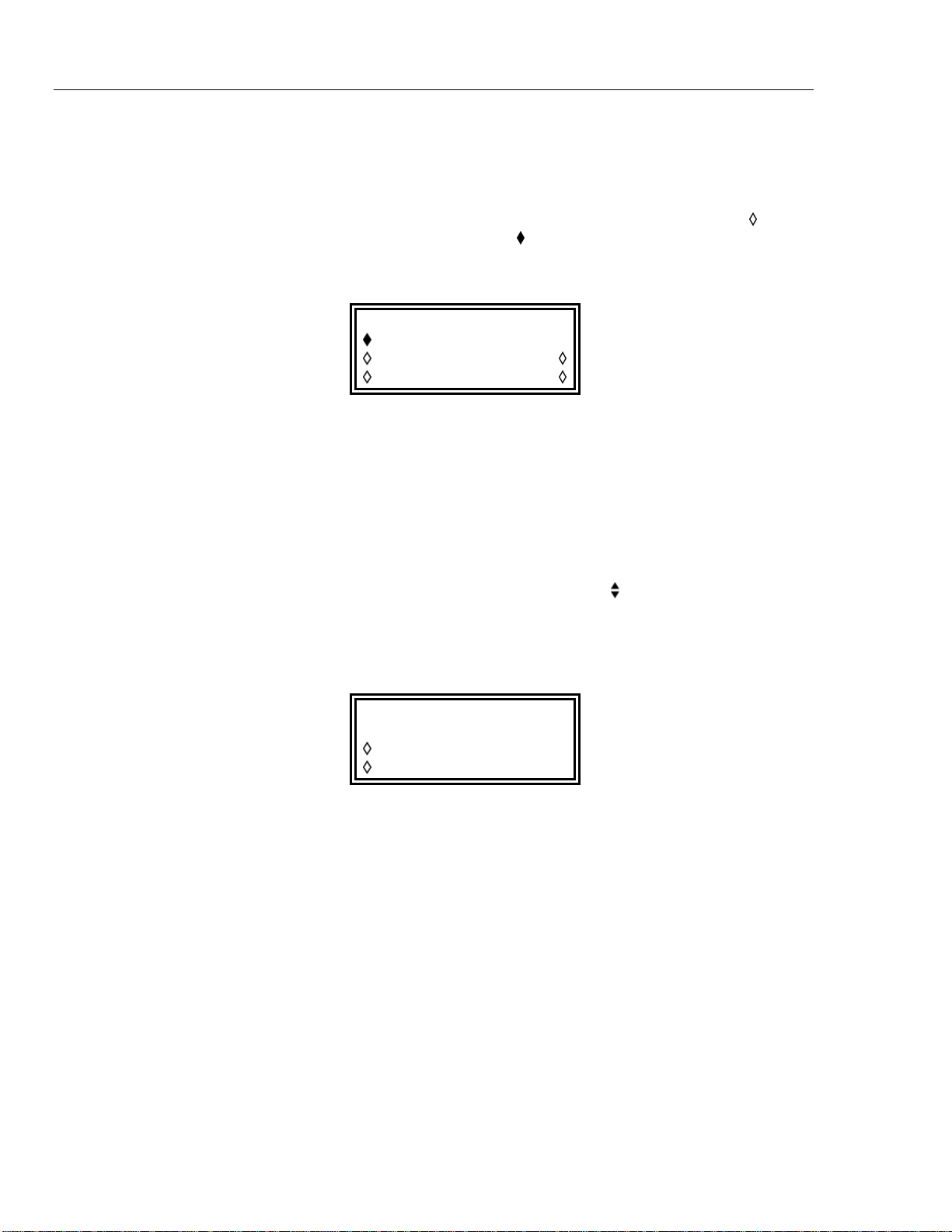
291, 292, 294
Users Manual
Note
On multi-channel instruments the channel to be edited must first be selected
by pressing the appropriate SETUP key; the lamp lights beside the
SETUP key of the channel currently enabled for editing.
A diamond beside a screen item indicates that it is selectable; hollow diamonds (
identify deselected items and filled diamonds (
) denote selected items. For example,
)
press MODE to get the screen shown below:
MODE:
continuous
gated setup…
triggered setup…
The filled diamond indicates that the selected mode is continuous. Gated or
triggered modes are selected by pressing the associated soft-key which will make
the diamond beside that item filled and the diamond beside continuous hollow.
This screen also illustrates how an ellipsis (three dots following the screen text) indicates
that a further screen follows when that item is selected. In the case of the MODE screen
illustrated, pressing the setup… soft-key on the bottom line brings up the
TRIGGER SETUP menu; note that selecting this item does not change the selection of
continuous, gated or triggered.
Some screen items are marked with a double-headed arrow (
) when selected to indicate
that the item’s setting can be changed by further presses of the soft-key, by pressing
either cursor key or by using the rotary control. For example, pressing FILTER brings
up the screen shown below.
FILTER
mode: auto
type: 40MHz eliptic
Repeated presses of the mode soft-key will toggle the mode between its two possible
settings of auto and manual. Similarly, when type is selected, repeated presses
of the type soft-key (or cursor keys or use of the rotary control) will step the selection
through all possible settings of the filter type.
In addition to their use in editing items identified by a double-headed arrow as described
above, the cursor keys and the rotary control operate in two other modes.
In screens with lists of items that can be selected (i.e. items marked with a diamond) the
cursor keys and rotary control are used to scroll all items through the display if the list
has more than three items; look, for example at the STD (standard waveform) and
UTILITY screens.
In screens where a parameter with a numeric value is displayed the cursor keys move the
edit cursor (a flashing underline) through the numeric field and the rotary control will
increment or decrement the value; the step size is determined by the position of the edit
cursor within the numeric field.
4-4
Find Quality Products Online at: [email protected]
www.GlobalTestSupply.com
Page 35
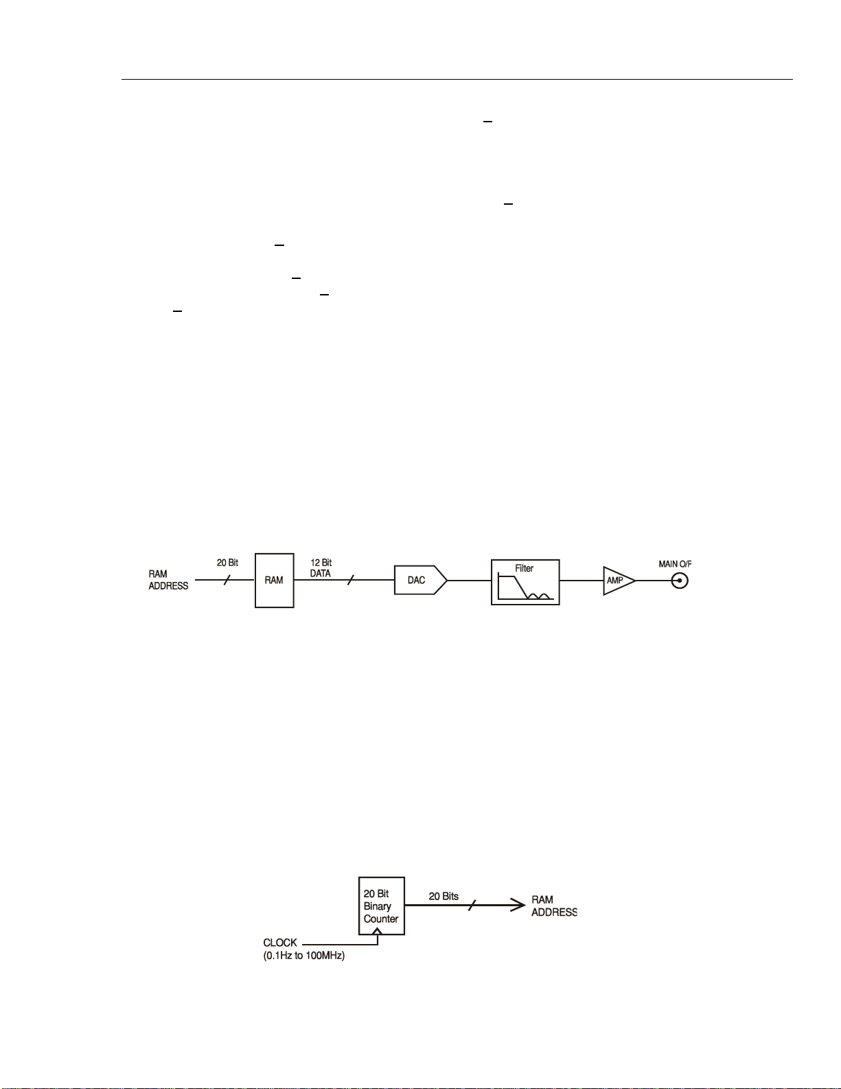
Initial Operation
Principles of Operation 4
Thus for STANDARD FREQUENCY set to 1.000000000 MHz rotating the control
will change the frequency in 1 kHz steps. The display will autorange up or down as the
frequency is changed, provided that autoranging permits the increment size to be
maintained; this will in turn determine the lowest or highest setting that can be achieved
by turning the control. In the example above, the lowest frequency that can be set by
rotating the control is 1 kHz, shown on the display as 1
.000000000 kHz.
This is the limit because to show a lower frequency the display would need to autorange
below 1 kHz to x
xx.xxxxxx Hz, in which the most significant digit represents
100 Hz, i.e. the 1 kHz increment would be lost. If, however, the starting frequency had
been set to 1.0000
autoranged at 1 kHz to 9
00.0000000 Hz without losing the 100 Hz increment.
1
00000 MHz , i.e. a 100 Hz increment, the display would have
00.0000000 Hz and could then be decremented further to
Turning the control quickly will step numeric values in multiple increments.
Principles of Operation
The instrument operates in one of two different modes depending on the waveform
selected. Direct digital synthesis (DDS) mode is used for sine, cosine, haversine,
triangle, sin(x)/x and ramp waveforms. Clock synthesis mode is used for square, pulse,
pulse train, arbitrary and sequence.
In both modes the waveform data is stored in RAM. As the RAM address is incremented
the values are output sequentially to a digital-to-analogue converter (DAC) which
reconstructs the waveform as a series of voltage steps which are subsequently filtered
before being passed to the MAIN OUT connector.
Figure 4-1. Single-Channel Simplified Block Diagram
The main differences between DDS and clock synthesis modes are the way in which the
addresses are generated for the RAM and the length of the waveform data.
Clock Synthesis Mode
In clock synthesis mode the addresses are always sequential (an increment of one) and
the clock rate is adjusted by the user in the range 100 MHz to 0·1 Hz. The frequency of
the waveform is the clock frequency divided by the waveform length, thus allowing short
waveforms to be played out at higher repetition rates than long waveforms.
For example the maximum frequency of an eight-point waveform is 100e6÷8 or
12.5 MHz, but a 1000-point waveform has a maximum frequency of 100e6÷1000 or
100 kHz.
shc0004f.emf
Figure 4-2. Clock Synthesis Mode
4-5
Find Quality Products Online at: [email protected]
www.GlobalTestSupply.com
shc0005f.emf
Page 36
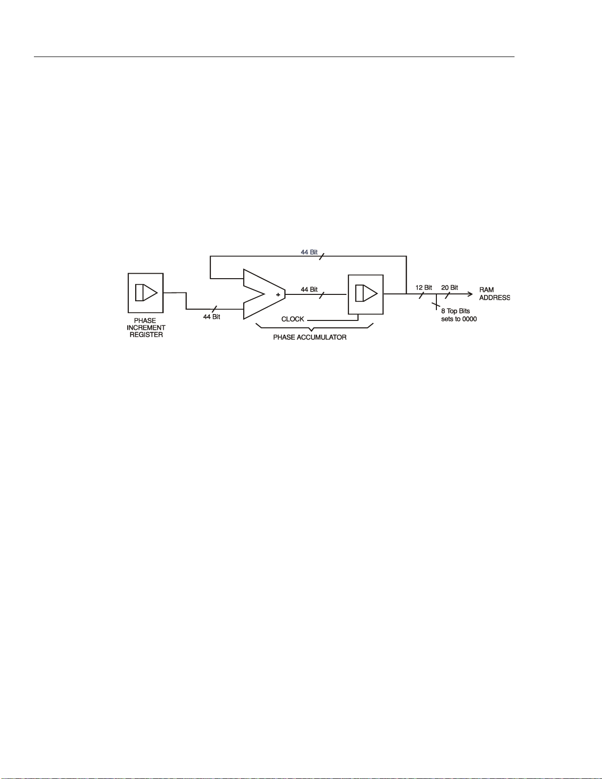
291, 292, 294
Users Manual
DDS Mode
Arbitrary waveforms have a user defined length of 8 to 1,048,576 points. Square waves
use a fixed length of 2 points and pulse and pulse train have their length defined by the
user selected period value.
In DDS mode all waveforms are stored in RAM as 4096 points. The frequency of the
output waveform is determined by the rate at which the RAM addresses are changed.
The address changes are generated as follows:
The RAM contains the amplitude values of all the individual points of one cycle (360 º)
of the waveform; each sequential address change corresponds to a phase increment of the
waveform of 360/4096 degrees. Instead of using a counter to generate sequential RAM
addresses, a phase accumulator is used to increment the phase.
Figure 4-3. Direct Digital Synthesis Mode
shc0006f.emf
On each clock cycle the phase increment, which has been loaded into the phase increment
register by the CPU, is added to the current result in the phase accumulator; the 12 most
significant bits of the phase accumulator drive the lower 12 RAM address lines, the upper
8 RAM address lines being held low. The output waveform frequency is now determined
by the size of the phase increment at each clock. If each increment is the same size then
the output frequency is constant; if it changes, the output frequency changes as in sweep
mode.
The generator uses a 44 bit accumulator and a 100 MHz clock frequency; the frequency
setting resolution is 0·1 mHz.
Only the 12 most significant bits of the phase accumulator are used to address the RAM.
At a waveform frequency equal to the clock frequency divided by 4096, approximately
24.4 kHz, the natural frequency, the RAM address increments at every clock. At all
frequencies below this (i.e. at smaller phase increments) one or more addresses are output
for more than one clock period because the phase increment is not big enough to step the
address at every clock. Similarly at frequencies above the natural frequency the larger
phase increment causes some addresses to be skipped, giving the effect of the stored
waveform being sampled; different points will be sampled on successive cycles of the
waveform.
4-6
Find Quality Products Online at: [email protected]
www.GlobalTestSupply.com
Page 37

Chapter 5
Standard Waveforms
Title Page
Introduction........................................................................................................ 5-2
Standard Waveform Operation.......................................................................... 5-2
Setting Generator Parameters ............................................................................ 5-2
Waveform Selection...................................................................................... 5-2
Frequency...................................................................................................... 5-2
Amplitude...................................................................................................... 5-3
DC Offset ...................................................................................................... 5-4
Warning and Error Messages............................................................................. 5-5
Synchronization Output..................................................................................... 5-6
5-1
Find Quality Products Online at: [email protected]
www.GlobalTestSupply.com
Page 38
291, 292, 294
Users Manual
Introduction
Standard Waveform Operation
This section deals with the use of the instrument as a standard function generator, i.e.
generating sine, square, triangle, dc, ramp, haversine, cosine, havercosine and sin(x)/x
waveforms. All but the square wave are generated by DDS which gives 10-digit
frequency resolution; the square wave is generated by clock synthesis which results in
only 8-digit frequency resolution. Refer to Principles of Operation in chapter 4 for an
explanation of the differences.
The STANDARD WAVEFORMS screen also includes arbitrary and sequence for
simplicity of switching between these and standard waveforms; they do, however, have
their own screens (accessed by pressing ARB and SEQUENCE respectively) and are
described in detail in their appropriate sections. Pulse and pulse-train are also accessed
from the standard waveforms screen but are sufficiently different to justify their own
section in this manual.
Much of the following descriptions of amplitude and offset control, as well as of mode,
sweep, etc., in the following sections, apply to arbitrary and sequence as well as standard
waveforms; for clarity, any differences of operation with arbitrary, sequence, pulse and
pulse-train are described only in those sections.
Setting Generator Parameters
Waveform Selection
Pressing the STD key gives the STANDARD WAVEFORMS screen which lists all the
waveforms available:
STANDARD WAVEFORMS
sine
square
triangle
The rotary control or cursor keys can be used to scroll the full list back and forward
through the display. The currently selected waveform (sine with the factory defaults
setting) is indicated by the filled diamond; the selection is changed by pressing the softkey beside the required waveform.
Frequency
Pressing the FREQ key gives the STANDARD FREQUENCY screen:
STANDARD FREQUENCY
10.00
freq period
000000 kHz
With freq selected as shown above, the frequency can be entered directly from the
keyboard in integer, floating point or exponential format. For example, 12·34 kHz can be
5-2
Find Quality Products Online at: [email protected]
www.GlobalTestSupply.com
Page 39
Standard Waveforms
Setting Generator Parameters 5
entered as 12340, 12340·00, or 1·234 exp 4 etc. However, the display will always
show the entry in the most appropriate engineering units, in this case
12·34000000 kHz.
With period selected instead of freq the frequency can be set in terms of a period,
for example 123·4 µs can be entered as·0001234 or 123·4 exp -6; again the display will
always show the entry in the most appropriate engineering units. Note that some rounding
may occur when switching between frequency and period or vice-versa.
Square wave, generated by clock synthesis, has 8-digit resolution for both frequency and
period entry.
Turning the rotary control will increment or decrement the numeric value in steps
determined by the position of the edit cursor (flashing underline); the cursor is moved
with the left- and right-arrowed cursor keys.
Note that the upper frequency limits vary for the different waveform types; refer to the
Specifications section in chapter 1 for details.
Amplitude
Pressing the AMPL key gives the AMPLITUDE screen:
AMPLITUDE:
+20.0 Vpp
Vpp Vrms
dBm load:hiZ
The waveform amplitude can be set in terms of peak-to-peak volts (Vpp), rms volts
(Vrms) or dBm (referenced to a 50 Ω or 600 Ω load). For Vpp and Vrms the level
can be set assuming that the output is open-circuit (load:hiZ) or terminated
(load:50
and the load:hiZ setting is automatically changed to load:50
Ω or load:600Ω); when dBm is selected termination is always assumed
Ω. Note that the actual
generator output impedance is always 50 Ω; the displayed amplitude values for 600 Ω
termination take this into account.
With the appropriate form of the amplitude selected (indicated by the filled diamond) the
amplitude can be entered directly from the keyboard in integer, floating point or
exponential format. For example 250 mV can be entered as·250 exp -3 or 250, etc. The
display will always show the entry in the most appropriate engineering units, in this case
250 mV.
Turning the rotary control will increment or decrement the numeric value in steps
determined by the position of the edit cursor (flashing underline); the cursor is moved
with the left- and right-arrowed cursor keys.
Alternate presses of the ± key will invert the signal at the MAIN OUT socket; if the
DC OFFSET is non-zero the signal is inverted about the same offset. The exception to
this occurs when the amplitude is specified in dBm. Since low level signals are specified
in -dBm (0 dBm = 1 mW into 50 Ω = 0.224 mV rms) the - sign is interpreted as part of a
new amplitude entry and not as a command to invert the signal.
Note that for DC, sin(x)/x, pulse train, arbitrary and sequence, the amplitude can only be
displayed and entered in the Vpp form; further limitations on pulse-train, arbitrary and
sequence amplitude are discussed in the appropriate sections.
5-3
Find Quality Products Online at: [email protected]
www.GlobalTestSupply.com
Page 40
291, 292, 294
Users Manual
DC Offset
Pressing the OFFSET key gives the DC OFFSET screen:
DC OFFSET:
program +0.00 mVdc
(actual +0.00 mVdc)
load:hiZ
The offset can be entered directly from the keyboard in integer, floating point or
exponential format, for example 100 mV can be entered as 0.001 or as 100 exp -3, etc.
The display will always show the entry in the most appropriate engineering units, in this
case 100 mV. During a new offset entry the ± key can be used at any time to invert the
offset; alternate presses toggle the sign between + and -.
Turning the rotary control will increment or decrement the numeric value in steps
determined by the position of the edit cursor (flashing underline); the cursor is moved
with the left- and right-arrowed cursor keys. Because the dc offset can have negative
values, the rotary control can take the value below zero; although the display may
autorange to a higher resolution if a step takes the value close to zero, the increment size
is maintained correctly as the offset is stepped negative. For example, if the display
shows
program = +2
05· mVdc
with the cursor in the most significant digit, the rotary control will decrement the offset in
100 mV steps as follows:
program = +2
program = +1
program = +5
program = -9
program = -1
05· mVdc
05· mVdc
·00 mVdc
5·0 mVdc
95· mVdc
The actual dc offset at the MAIN OUT socket is attenuated by the fixed-step output
attenuator when this is in use. Since it is not obvious when the signal is being attenuated
the actual offset is shown in brackets as a non-editable field below the programmed
value.
For example, if the amplitude is set to 2·5 V p-p the output is not attenuated by the fixed
attenuator and the actual dc offset (in brackets) is the same as that set. The DC OFFSET
display shows:
DC OFFSET:
program +1.5
0 Vdc
(actual +1.50 Vdc)
load: hiZ
If the amplitude is now reduced to, say, 250 mV p-p, this introduces the attenuator and
the actual dc offset changes by the appropriate factor:
5-4
Find Quality Products Online at: [email protected]
www.GlobalTestSupply.com
Page 41

Standard Waveforms
DC OFFSET:
program +1.5
(actual +151 mVdc)
load: hiZ
The above display shows that the set dc offset is +1.50 V but the actual offset is
+151 mV.
The actual offset value also takes into account the true attenuation provided
by the fixed attenuator, using the values determined during the calibration
procedure. In the example displayed the output signal is 250 mV p-p
exactly and takes account of the small error in the fixed attenuator; the
offset is 151 mV (to three significant figures) and takes account of the effect
of the calibrated attenuation error on the set offset of 1.50 V.
Whenever the set dc offset is modified by a subsequent change in output level the display
shows a warning message. Similarly, settings which would result in peak offset+signal
levels outside the range ±10 V (and therefore clipping) generate a similar warning
message. There is additional information on these messages in the Warnings and Error
Messages section below.
0 Vdc
Note
Warning and Error Messages 5
The output attenuation is controlled intelligently to minimize the difference between the
programmed and actual offset when the combination of programmed amplitude and
offset allows this. Thus when the offset is set to 150 mV, for example, the amplitude can
be reduced to nominally 50 mV p-p before the fixed attenuator causes the actual offset to
be different from the programmed value.
Warning and Error Messages
Two classes of message are displayed on the screen when an illegal combination of
parameters is attempted.
WARNING messages are shown when the entered setting causes some change which the
user might not necessarily expect, as in the following two examples:
1. Changing the amplitude from, for example, 2·5 V p-p to 25 mV p-p brings in the step
attenuator; if a non-zero offset has been set then this will also be attenuated. The
message DC offset changed by amplitude will be shown temporarily
on the screen but the setting will be accepted; in this case the actual attenuated offset
will be shown in brackets below the set value.
2. With the output level set to 10 V p-p, increasing the dc offset beyond ±5 V will cause
the message Offset + Sum + level may cause clipping. The offset
change will be accepted (producing a clipped waveform) and the user may then
choose to change the output level or the offset to produce a signal which is not
clipped. The word (clip?) will show in the display beside AMPLITUDE or
DC OFFSET while the clipped condition exists.
ERROR messages are shown when an illegal setting is attempted, most generally a
number outside the range of values permitted. In this case the entry is rejected and the
parameter setting is left unchanged, as in the following three examples:
1. Entering a frequency of 1 MHz for a triangle waveform. The error message:
Frequency out of range for the selected waveform is
shown.
5-5
Find Quality Products Online at: [email protected]
www.GlobalTestSupply.com
Page 42
291, 292, 294
Users Manual
2. Entering an amplitude of 25 V p-p. The error message:
Maximum output level exceeded is shown.
3. Entering a dc offset of 20 V. The error message:
Maximum DC offset exceeded is shown.
The messages remain on the display for approximately two seconds. The last two
messages can be viewed again by pressing the last error… soft-key on the
UTILITY screen. Refer to the section System Operations from the Utility Screen for
more information.
Each message has a number and the full list appears in appendix B.
The default set-up is for all warning and error messages to be displayed and for a beep to
sound with each message. This set-up can be changed on the error… menu on the
UTILITY screen. The error menu is shown below:
error beep: ON
error message: ON
warn beep: ON
warn message: ON
Each feature can be turned on and off with alternate presses of the associated soft-key;
the factory default is for all features to be on.
Synchronization Output
SYNC OUT is a multifunction CMOS/TTL level output that can be automatically or
manually set to be any of the following:
waveform sync: A square wave with 50 % duty cycle at the main waveform
frequency, or a pulse coincident with the first few points of
an arbitrary waveform. Can be selected for all waveforms.
position marker: If an arbitrary waveform is selected, any point(s) on the
main waveform may have associated marker bit(s) set high
or low. These will then show as pulses when
position marker is selected.
burst done: Produces a pulse coincident with the last cycle of the burst.
sequence sync: Produces a pulse coincident with the end of a waveform
sequence.
trigger: Selects the current trigger signal (internal, external or
manual). Useful for synchronizing burst or gated signals.
sweep sync: Outputs the sweep trigger and sweep marker signals.
phase lock: Used to synchronize two or more generators. Produces a
positive edge at the 0 º phase point.
The setting up of the signals themselves is discussed in the relevant sections later in this
manual. Triggering is described in the Triggered Burst and Gate chapter and
position marker in the Arbitrary Waveform Generation chapter.
Pressing the SYNC OUT key calls the SYNC OUT set-up screen:
5-6
Find Quality Products Online at: [email protected]
www.GlobalTestSupply.com
Page 43

Standard Waveforms
SYNC OUT
output: on
mode: auto
src: waveform sync
SYNC OUT is turned on and off by alternate presses of the output soft-key.
The selection of the signal to be output from the SYNC OUT socket is made using the
src (source) soft-key; repeated presses of src cycle the selection through all the
choices (waveform sync, position marker, etc.) listed above. Alternatively,
with the src selected (double-headed arrow) the rotary control or cursor keys can be
used to step backwards and forwards through the choices.
The source selection of the SYNC OUT waveform can be made automatic (auto) or
user-defined (manual) with alternate presses of the mode soft-key. In automatic
mode the SYNC OUT waveform most appropriate for the current main waveform is
selected.
For example, waveform sync is automatically selected for all continuous standard
and arbitrary waveforms, but trigger is selected in trigger or gated waveform
modes. The automatic selection will be mentioned in each of the appropriate main
waveform mode sections and a full table is given in the appendix.
Synchronization Output 5
The automatic selection can still be changed manually by the src soft-key even when
auto mode has been selected but the selection will immediately revert to the automatic
choice as soon as any relevant parameter (for example, main waveform frequency or
amplitude) is adjusted. You must select manual with the mode soft-key for a source
other than the automatic choice to remain set. The auto selection will generally set
the most frequently used signal, for example waveform sync for all continuous
main waveforms, but you will need to use manual for any special requirements, such
as position markers on arbitrary waveforms.
5-7
Find Quality Products Online at: [email protected]
www.GlobalTestSupply.com
Page 44

Chapter 6
Sweep Operation
Title Page
General............................................................................................................... 6-2
Principles of Sweep Operation...................................................................... 6-2
Connections for Sweep Operation................................................................. 6-2
Setting sweep parameters................................................................................... 6-2
Sweep Range................................................................................................. 6-3
Sweep Time................................................................................................... 6-3
Sweep Type................................................................................................... 6-4
Sweep Spacing............................................................................................... 6-5
Sweep Marker................................................................................................ 6-5
Sweep Hold ................................................................................................... 6-5
6-1
Find Quality Products Online at: [email protected]
www.GlobalTestSupply.com
Page 45
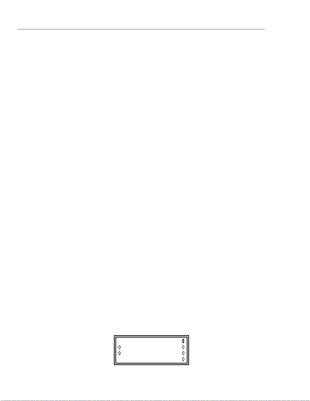
291, 292, 294
Users Manual
General
Principles of Sweep Operation
All standard and arbitrary waveforms can be swept with the exception of pulse, pulsetrain and sequence. During sweep all waveforms are generated in DDS mode because
this offers the significant advantage of phase-continuous sweeps over a very wide
frequency range (up to 10
actually stepped, not truly linearly swept, and thought needs to be given as to what the
instrument is actually doing when using extreme combinations of sweep range and time.
For DDS operation during sweep all waveforms must be 4096 points in length; this is the
natural length for standard waveforms but all arbitrary waveforms are expanded or
condensed in software to 4096 points when Sweep is turned on. This does not affect the
original data.
Sweep mode is turned on and off either by the on or off soft key on the
SWEEP SETUP screen accessed by pressing the SWEEP front panel key, or by the
sweep soft key on the MODE screen. In multi-channel instruments two or more
channels can be swept simultaneously.
When sweep is turned on the software creates a table of 2000 frequencies between, and
including, the specified start and stop values. Because any frequency used in sweep
mode must be one of the tabled values, the centre frequency displayed (see Sweep range
below) may not be the exact midpoint and markers (see Sweep marker below) may not be
exactly at the programmed frequency. The frequency resolution of the steps will be
particularly coarse with wide sweeps.
10
:1). However, it must be remembered that the frequency is
Connections for Sweep Operation.
Sweeps are generally used with an oscilloscope or hard-copy device to investigate the
frequency response of a circuit. The MAIN OUT is connected to the circuit input and the
circuit output is connected to an oscilloscope or, for slow sweeps, a recorder.
An oscilloscope or recorder can be triggered by connecting its trigger input to the
generator’s SYNC OUT, which defaults to sweep sync when sweep is turned on.
The sweep sync signal goes high at the start of sweep and remains high for the duration
of the first frequency step.
To show a marker on the display instrument the SYNC OUT can be set to additionally
output a marker pulse. See Sweep marker below for setting the marker frequency.
For triggered sweeps, a trigger signal may be provided by any of the possible trigger
sources, i.e. internal, external, manual or remote.
The generator does not provide a ramp output for use with X-Y displays or recorders.
Setting sweep parameters
Pressing the SWEEP key (or the sweep set-up soft key on the MODE screen) displays
the SWEEP SETUP screen:
SWEEP SETUP: off
range… type…
time… spacing…
marker…
6-2
Find Quality Products Online at: [email protected]
www.GlobalTestSupply.com
Page 46
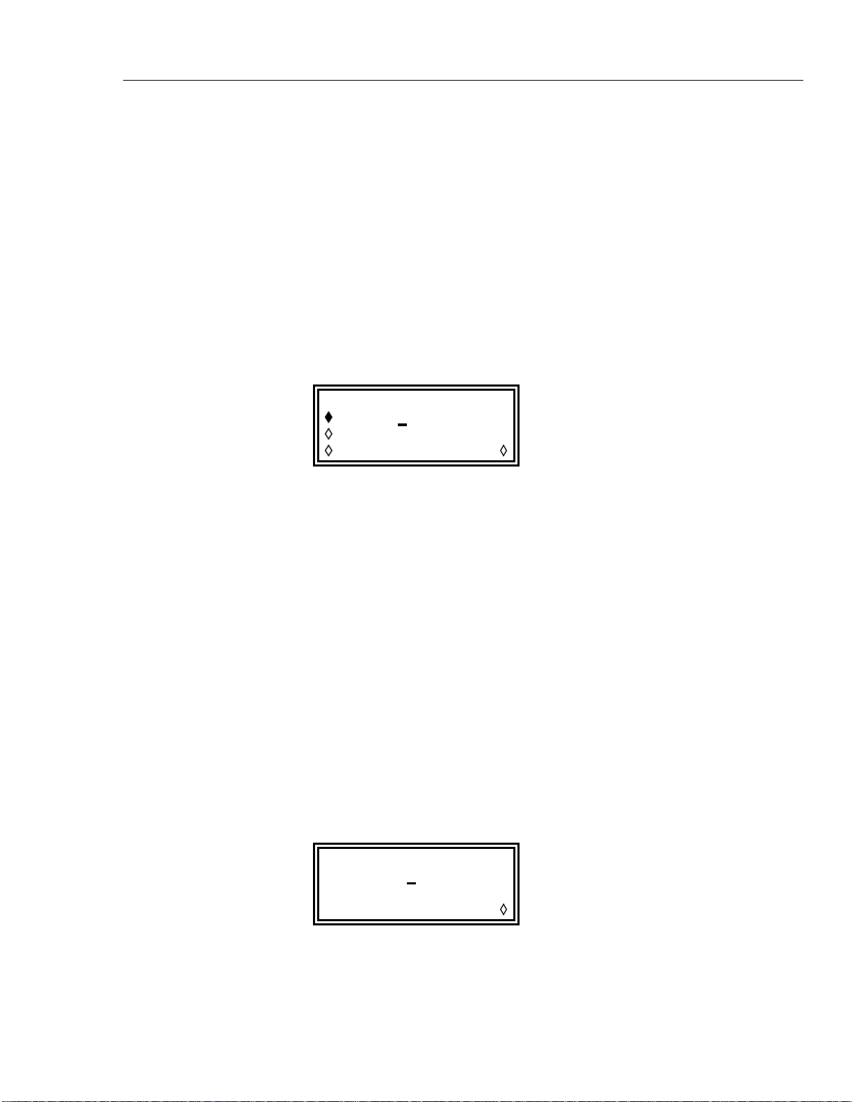
Sweep Operation
Menus for setting up the range, time (sweep rate), type (continuous, triggered, etc.)
spacing (lin/log) and marker position are all accessed from this screen using the
appropriate soft key. Sweep mode itself is turned on and off with alternate presses of the
on/off soft key; sweep can also be turned on by the sweep soft key on the MODE
screen.
On multi-channel instruments two or more channels can be swept at once. The channels
to be swept are set on or off by selecting them in turn with the appropriate SETUP key
and then using the on/off soft key of the SWEEP SETUP screen.
On all the following menus, pressing the done soft key returns the display to this
SWEEP SETUP screen.
Sweep Range
Pressing the range… soft key calls the SWEEP RANGE screen.
SWEEP RANGE:
start 100.0 kHz
stop 10.00 MHz
centr/span done
Setting sweep parameters 6
The maximum sweep range for all waveforms is 1 mHz to 40 MHz, including triangle,
ramp and square wave (which have different limits in unswept operation).
Sweep range can be defined by start and stop frequencies or in terms of a centre
frequency and span. start and stop soft keys permit the two end points of the
sweep to be set directly from the keyboard or by using the rotary control. The start
frequency must be lower than the stop frequency (but see Sweep type below for selecting
sweep direction).
Pressing the centr/span soft key changes the screen to permit entry in terms of
centre frequency and sweep span about that frequency; pressing the start/stop soft
key on that screen returns the display to the start and stop frequency form of entry.
Note that when the sweep is displayed in terms of centre frequency and span the span will
always be the exact difference between start and stop frequencies but the centre
frequency shown will be that of the frequency step nearest the true centre frequency, as
described above.
Sweep Time
Pressing the time… soft key calls the SWEEP TIME screen.
SWEEP TIME:
0.01
done
0 sec
The sweep time can be set from 1 ms to 999 s with 4 digit resolution by direct keyboard
entry or by using the rotary control.
6-3
Find Quality Products Online at: [email protected]
www.GlobalTestSupply.com
Page 47
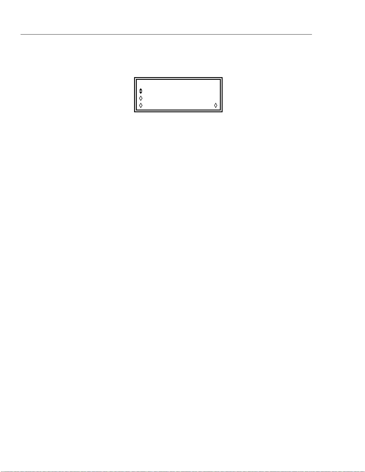
291, 292, 294
Users Manual
Sweep Type
Pressing the type… soft key calls the SWEEP TYPE screen.
SWEEP TYPE:
continuous
direction: up
sync: on done
This screen is used to set the sweep mode (continuous; triggered;
trig'd, hold/reset) and the sweep direction.
Successive presses of the direction soft key select one of the following sweep directions:
up start frequency to stop frequency.
down stop frequency to start frequency.
up/down start frequency to stop frequency and back to start frequency.
down/up stop frequency to start frequency and back to stop frequency.
The total sweep time is always that set on the SWEEP TIME screen, i.e. for up/down
and down/up operation the sweep time in each direction is half the total. Similarly the
total number of steps is the same for all choices, i.e. there will be half the number of steps
in each direction for up/down and down/up operation. In the sweep mode
descriptions which follow the direction is assumed to be up but all modes can be used
with all sweep directions.
In continuous mode the generator sweeps continuously between the start and stop
frequencies, triggered repetitively by an internal trigger generator whose frequency is
determined by the sweep time setting. At the stop frequency the generator resets to the
start frequency and begins a new sweep. If sync is set to on (the default) the
generator steps instantaneously from the stop frequency to zero frequency (i.e. it does not
dwell at the stop frequency for the full step interval) and then starts the next sweep from
the first point of the waveform, synchronized to the internally generated trigger signal.
This is useful because the sweep always starts from the same point in the waveform but
the waveform discontinuity can be undesirable in some circumstances, for example filter
evaluation. With sync set to off the frequency steps directly and phase
continuously from the stop frequency to the start frequency (after dwelling at the stop
frequency for the full step interval) but is not synchronized with the software generated
trigger signal.
In triggered mode the generator holds the output at the start frequency until it
recognizes a trigger. When triggered, the frequency sweeps to the stop frequency, resets,
and awaits the next trigger. If sync is set to on the frequency resets to zero
frequency (i.e. no waveform) and starts a new sweep at the first point of the waveform
when the next trigger is recognized. If sync is set to off the waveform resets to the
start frequency and runs at that frequency until the next trigger initiates a new sweep.
In trig’d, hold/reset mode the generator holds the output at the start frequency
until it recognizes a trigger; when triggered, the frequency sweeps to the stop frequency
and holds. At the next trigger the output is reset to the start frequency where it is held
until the next sweep is initiated by a further trigger. If sync is set to off the output
operates exactly as described above; if sync is set to on the output resets to zero
frequency (i.e. no waveform) and starts a new sweep at the first point of the waveform.
For triggered sweeps a trigger signal may be provided by any of the possible trigger
sources, i.e. internal, external, manual or remote.
6-4
Find Quality Products Online at: [email protected]
www.GlobalTestSupply.com
Page 48
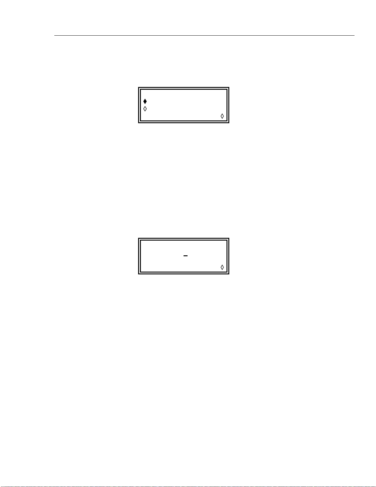
Sweep Operation
Sweep Spacing
Pressing the spacing… soft key on the SWEEP SETUP screen calls the
SWEEP SPACING screen.
SWEEP SPACING:
logarithmic
linear
done
With linear selected the sweep changes the frequency at a linear rate; with
logarithmic selected the sweep spends an equal time in each frequency decade.
Sweep Marker
A sweep marker pulse is also available from the SYNC OUT socket when
sweep sync (the default condition) is selected. The marker pulse is differentiated
from the sweep sync pulse by being approximately half the amplitude of the sync pulse;
this permits the trigger level of the display oscilloscope to be adjusted for the sweep sync
pulse without additionally triggering on the marker pulse.
Setting sweep parameters 6
The marker pulse frequency is set from the SWEEP MARKER FREQ menu, called by
pressing the marker… soft key on the SWEEP SETUP screen.
A new marker frequency can be programmed directly from the keyboard or by using the
rotary control and cursor keys. Note that the marker frequency can only be one of the
values in the sweep frequency table; any value in the sweep range can be entered but the
value used will be the nearest frequency in the table. When sweep is turned on, the actual
marker frequency is shown in the non-editable field below the programmed frequency.
For the default sweep setting of 100 kHz to 10 MHz in 50 ms, the actual frequency of a
5 MHz marker is 4·998 MHz.
The marker duration is the sweep time divided by 2000, i.e. the dwell time at a single
frequency step.
To avoid displaying a sweep marker, the marker frequency is simply set to a value
outside the current sweep frequency range.
Sweep Hold
The sweep can be held and restarted at any time at or from its current frequency by
alternate presses of the MAN HOLD key or remote command.
SWEEP MARKER FREQ:
progrm: 5.0
actual: 4.977 MHz
done
00 MHz
6-5
Find Quality Products Online at: [email protected]
www.GlobalTestSupply.com
Page 49

Chapter 7
Triggered Burst and Gate
Title Page
General............................................................................................................... 7-2
Internal Trigger Generator............................................................................. 7-2
External Trigger Input................................................................................... 7-2
Adjacent Channel Trigger Output ................................................................. 7-3
Triggered Burst.................................................................................................. 7-3
Trigger Source............................................................................................... 7-4
Trigger Edge.................................................................................................. 7-4
Burst Count.................................................................................................... 7-4
Start Phase..................................................................................................... 7-5
Manual Initialization of Inter-Channel Triggering........................................ 7-5
Gated mode........................................................................................................ 7-6
Gate Source ................................................................................................... 7-6
Gate Polarity.................................................................................................. 7-6
Start Phase..................................................................................................... 7-6
Sync Out in Triggered Burst and Gated Modes................................................. 7-7
7-1
Find Quality Products Online at: [email protected]
www.GlobalTestSupply.com
Page 50
291, 292, 294
Users Manual
General
Triggered burst and gated modes are selected from the MODE screen, called by the
MODE key, as alternatives to the default continuous mode.
MODE: off
continuous
gated setup…
triggered setup…
In triggered burst mode a defined number of cycles are generated following each trigger
event. This mode is edge triggered.
In gated mode the generator runs whenever the gating signal is true. This mode is level
sensitive.
Triggered burst mode and gated mode can be controlled by either the internal trigger
generator, an external trigger input, by the front panel MAN TRIG key or by remote
control.
In both modes the start phase, i.e. the starting point on the waveform cycle, can be
specified.
Internal Trigger Generator
The period of the internal trigger generator is set with the period soft key on the
TRIGGER IN set-up screen called by the TRIG IN key.
The internal trigger generator divides down a crystal oscillator to produce a 1:1 square
wave with a period from 0·01 ms (100 kHz) to 200 s (0·005 Hz). Generator period
entries that cannot be exactly set are accepted and rounded up to the nearest available
value, so that for example 0·109 ms is rounded to 0·11 ms.
When triggered burst or gated modes are selected the SYNC OUT source automatically
defaults to trigger which is the output of the internal trigger generator when internal
triggering or gating is specified.
In triggered burst mode the selected edge of each cycle of the trigger generator is used to
initiate a burst; the interval between bursts is therefore 0·01 ms to 200 s as set by the
generator period.
source: int force
slope: positive
level: +1.4 V
period: 1.00ms
In gated mode the output of the main generator is gated on whilst the internal trigger
generator output is true; the duration of the gate is therefore 0·005 ms to 100 s in step
with trigger generator periods of 0·01 ms to 200 s.
External Trigger Input
External trigger or gate signals are applied to the front panel TRIG IN socket which has a
variable threshold level set using the level soft-key; the level can be set from -5·0 V
7-2
Find Quality Products Online at: [email protected]
www.GlobalTestSupply.com
Page 51
Triggered Burst and Gate
to +5·0 V by direct keyboard entry or by using the rotary control. In triggered burst mode
the input is edge sensitive; the selected edge of each external trigger initiates the specified
burst. In gated mode the input is level sensitive; the output of the main generator is on
whilst the gate signal is true.
The minimum pulse width that can be used with TRIG IN in triggered burst and gated
m
odes is 50 ns and the maximum repetition rate is 1 MHz. The maximum signal level
that can be applied without damage is ±10 V.
When triggered burst or gated mode is selected the SYNC OUT source automatically
defaults to trigger, which is always a positive-edged version of the external trigger or
gate signal when external triggering or
Adjacent Channel Trigger Output
On multi-channel instruments the trigger out signal
the control signal for a triggered burst. The channel numbering ‘wraps round’, i.e.
channels 1 and 3 are obviously adjacent to channel 2 but so are channels 2 and 4 adjacent
to channel 1..
The source of the trigger out signal is selected by the source soft-key on the
TRIGGER OUT screen called by the TRIG IN key.
gating is specified.
of an adjacent channel can be used as
Triggered Burst 7
TRIGGER OUT:
mode: auto
source: wfm end
The TRIGGER OUT choices are as follows:
wfm end: Waveform end; a positive-going pulse coincident with the end of
a wavefor
pos’n marker: Position marker; arbitrary waveforms only. Any point(s) on the
main waveform
output if selected for a standard waveform.
seq sync: Sequence sync; a positive-going pulse coincident with the end of
a waveform
burst done: A positive-going pulse coincident with the end of the last cycle
of a burst.
The default choice is wfm end except when the channel is running a sequence in
which case it
default it is neces
soft key.
becomes seq sync. To set the trigger out to anything other than its
sary to change the mode from auto to manual using the mode
m cycle (and the start of the next).
may have marker bit(s) set high or low. No
sequence.
Trigger out is an internal signal but, as with the other trigger sources, a positive-edged
version is available at the triggered channel’s SYNC OUT with its default source of
trigger selected.
Triggered Burst
Triggered burst mode is turned on with the triggered soft key on the MODE
screen. The setup… soft key on this screen accesses the TRIGGER/GATE SETUP
7-3
Find Quality Products Online at: [email protected]
www.GlobalTestSupply.com
Page 52
291, 292, 294
Users Manual
Trigger Source
screen on which the burst count and start phase are set. The other trigger parameters are
set on the TRIGGER IN set-up screen called by pressing the TRIG IN key.
source: int force
slope: positive
level: +1.4 V
period: 1.00ms
The trigger source can be selected with the source soft key on the TRIGGER IN set-up
screen to be int, ext, man or an adjacent channel.
With int selected the internal trigger generator is used to initiate a burst; this generator
is set up as described in the previous section.
With ext selected the specified edge of the signal at TRIG IN is used to initiate a
burst.
With chan x selected (multi-channel instruments only) the trigger out signal from an
adjacent channel is used to initiate a burst; the source of the trigger out signal on that
channel x is set up as described in Adjacent Channel Trigger Output above.
With man selected as the source the only ways to initiate a burst are by pressing the
MAN TRIG key or by issuing a remote command. In multi-channel instruments pressing
MAN TRIG will trigger all those channels for which man has been selected as the
source.
Trigger Edge
The slope soft key is used to select the edge (positive or negative) of the
external trigger signal used to initiate a burst. The default setting of positive should
be used for triggering by the internal trigger generator or an adjacent channel's trigger
out.
Note that the trigger signal from SYNC OUT, used for synchronizing the display of a
triggered burst on an oscilloscope for example, is always positive-going at the start of the
burst.
Burst Count
The number of complete cycles in each burst following the trigger is set from the
TRIGGER/GATE SETUP screen called by pressing setup on the MODE screen.
TRIGGER/GATE SETUP:
burst cnt: 0000001
phase: +000.0º
(actual: +000.0º)
The required count can be set by pressing the burst cnt soft key followed by direct
entries from the keyboard or by using the rotary control. The maximum number of
waveform cycles that can be counted is 1,048,575 (2
7-4
Find Quality Products Online at: [email protected]
www.GlobalTestSupply.com
20
-1)
Page 53

Triggered Burst and Gate
Start Phase
The start phase, i.e. the point on the waveform cy
selected by pressing the phase soft key followed by direct entries from the keyboard
or by using the rotary control. Since the waveform cycle is always completed at the end
of the burst the start phase is also the stop phase.
The phase can be set with a precision of 0·1 ° but the actual resolution is limited with
me waveforms and at certain waveform frequencies as detailed below. To indicate
so
when this is the case the actual phase is shown in brackets as a non-editable field below
the programmed value.
To achieve start phase precision all waveforms are run in clock synthesis mode, i.e. as if
were arbitrary waveforms, when triggered burst is specified; this limits the
they
frequency resolution to 8 digits for all waveforms although the normally DDS generated
waveforms are still entered with 10 digit precision. Sine/cosine/haversine/etc. waveforms
are created as if they were arbitrary waveforms with the first point of the waveform
exactly at the start phase; each time the phase or frequency is changed the waveform is
recalculated. This can cause a slight lag if the parameters are changed quickly using the
rotary knob.
cle at which the burst starts, can be
Triggered Burst 7
The phase resolution of true arbitrary waveforms is li
the maximum resolution is 1 clock; thus waveforms with a length greater than 3600
points will have a resolution of 0·1 ° but below this number of points the maximum
resolution becomes 360 ° divided by the number of points.
Square waves, pulses, pulse trains and sequences have no start phase adjust
fixed at 0 °.
A summary of start phase capabilities in triggered burst mode is shown in the table
below:
Waveform
Sine, cosine, haversine
and havercosine
Square 2·5 MHz 0 ° only
Triangle 500 kHz ±360 °, 0·1 °
Ramp 500 kHz ±360 °, 0·1 °
Sin(x)/x 500 kHz ±360 °, 0·1 °
Pulse and pulse train 25 MHz 0 ° only
Arbitrary 100 Msamples/s clock ±360 °, 360 ÷ length or 0·1 °
Sequence 100 Msamples/s clock 0 ° only
Max waveform frequency Phase control range, resolution
2·5 MHz
mited by the waveform length since
ment; phase is
±360 °, 0·1 °
Manual Initialization of Inter-Channel Triggering
If a multi-channel instrument is set up such that all channels are triggered by
one it is possible to have a stable condition where all channels are waiting for a trigger
and the sequence of triggered bursts never starts. To overcome this problem any channel
can be triggered manually and independently using the force soft-key on that
channel’s TRIGGER IN screen. Select the channel to start the sequence with the
appropriate SETUP key, select the TR
press the force soft key.
7-5
Find Quality Products Online at: [email protected]
www.GlobalTestSupply.com
IGGER IN screen with the TRIG IN key and
an adjacent
Page 54
291, 292, 294
Users Manual
Gated mode
Gate Source
Gated mode is turned on with the gated soft key on the MODE screen. The
setup... soft key on this screen accesses the TRIGGER/GATE SETUP screen on
which the start phase is set. The other parameters associated with gated mode are set on
the TRIGGER IN set-up screen called by pressing the TRIG IN key.
source: int force
slope: positive
level: +1.4 V
period: 1.00ms
The gate signal source can be selected with the source soft key on the
TRIGGER IN set-up screen to be int, ext or an adjacent channel.
With int selected the internal trigger generator is used to gate the waveform; the
duration of the gate is half the generator period, (see Internal Trigger Generator above).
With ext selected the gate duration is from the threshold level set on the specified
edge of the signal at TRIG IN until the same level on the opposite edge; the threshold and
edge are set using the level and slope soft-keys respectively.
With chan x selected the trigger out signal from the adjacent channel x is used to gate
the waveform; the source of the trigger out signal on that channel x is set up as described
in Adjacent Channel Trigger Output above.
Gate Polarity
If slope on the TRIGGER IN set-up screen is set to positive the gate will
open at the threshold on the rising edge and close on the threshold of the falling edge of
an external gating signal, i.e. the gate signal is true when the TRIG IN signal is high. If
slope is set negative the gate signal is true when the TRIG IN signal is low. The
default setting of positive should be used for gating with the internal trigger
generator or an adjacent channel's trigger out.
Start Phase
Press setup… on the MODE screen to access the TRIGGER/GATE SETUP screen
on which the start phase can be set.
TRIGGER/GATE SETUP:
BURST CNT: 0000001
PHASE: +000·0º
(actual: +000·0º)
The start phase, i.e. the point on the waveform cycle at which the gated waveform starts,
can be selected by pressing the phase soft key followed by direct entries from the
keyboard, or by using the rotary control. Since the waveform cycle is always completed
at the end of the gated period the start phase is also the stop phase.
7-6
Find Quality Products Online at: [email protected]
www.GlobalTestSupply.com
Page 55

Triggered Burst and Gate
The phase can be set with a precision of 0·1 ° but the actual resolution is limited with
some waveforms and at certain waveform frequencies as detailed below. To indicate
when this is the case the actual phase is shown in brackets as a non-editable field below
the programmed value.
To achieve start phase precision all waveforms are run in clock synthesis mode, i.e. as if
were arbitrary waveforms, when gated mode is specified; this limits actual
they
frequency resolution to 8 digits for all waveforms although the normally DDS generated
waveforms are still entered with 10−digit precision. Sine/cosine/haversine etc.
waveforms are created as if they were arbitrary waveforms with the first point of the
waveform exactly at the start phase; each time the phase or frequency is changed the
waveform is recalculated. This can cause a slight lag if the parameters are changed
quickly using the rotary knob.
The phase resolution of true arbitrary waveforms is limited by the waveform length since
the maxim
points will have a resolution of 0·1 ° but below this number of points the maximum
resolution becomes 360 ° divided by the number of points.
um resolution is 1 clock; thus waveforms with a length greater than 3600
Sync Out in Triggered Burst and Gated Modes 7
Square waves, pulse, pulse trains and sequences have
fixed at 0 °. Refer to the table in the Triggered Burst section above for a summary of
start phase capabilities.
no start phase adjustment; phase is
Sync Out in Triggered Burst and Gated Modes
When triggered burst or gated modes are selected the SYNC OUT source automatically
defaults to trigger; this is a positive-edged signal synchronized to the actual trigger
used whether internal (from the internal trigger generator or an adjacent channel) or
external of either polarity.
Alternatively, SYNC OUT can be set to burst done
screen; in this case it provides a signal which is low while the waveform is running and
high at all other times.
on the SYNC OUT set-up
7-7
Find Quality Products Online at: [email protected]
www.GlobalTestSupply.com
Page 56

Chapter 8
Tone Mode
Title Page
Introduction........................................................................................................ 8-2
Tone Frequency............................................................................................. 8-2
Tone Type...................................................................................................... 8-2
Tone Switching Source.................................................................................. 8-3
DTMF Testing With Two Sources................................................................ 8-3
8-1
Find Quality Products Online at: [email protected]
www.GlobalTestSupply.com
Page 57
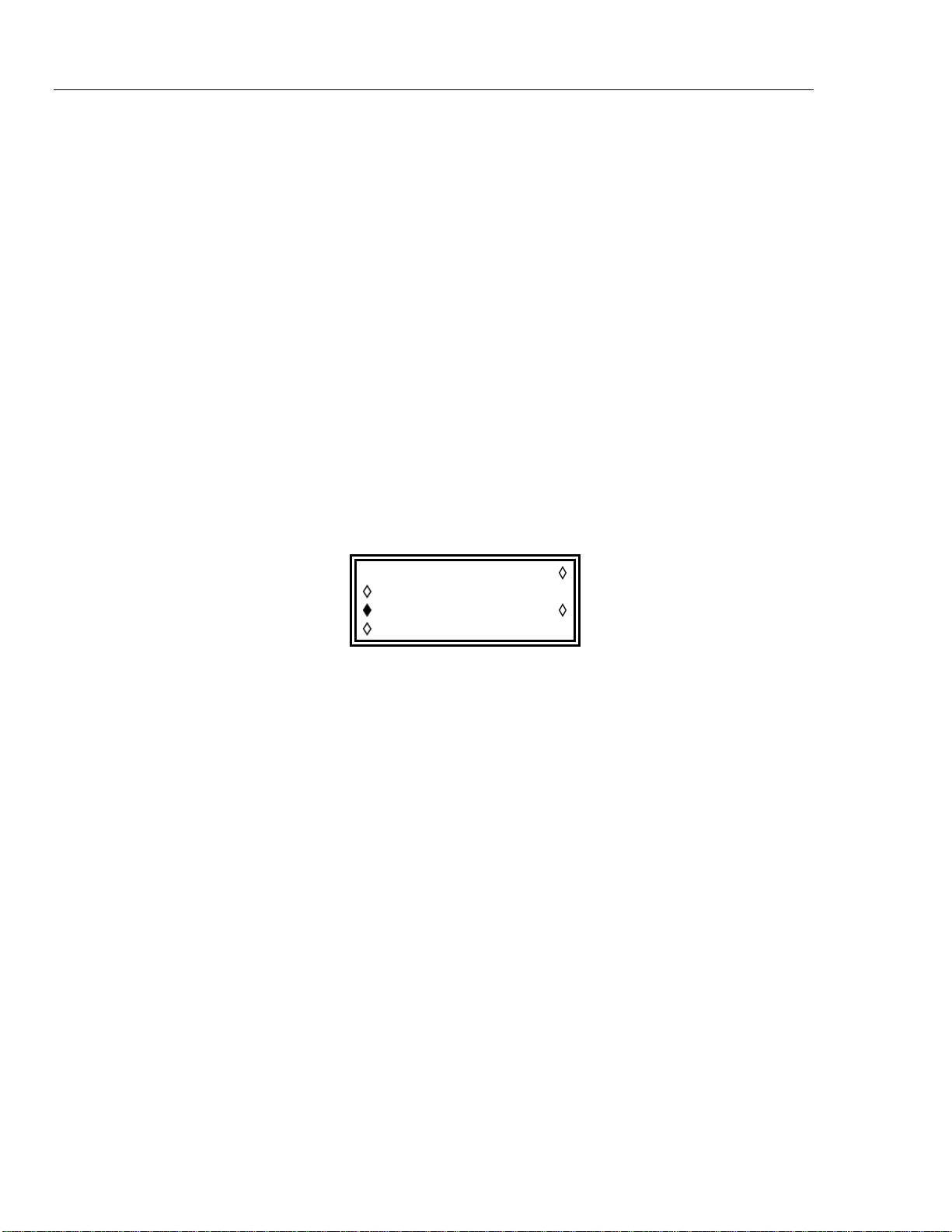
291, 292, 294
Users Manual
Introduction
Tone Frequency
In tone mode the output is stepped through a user-defined list of up to 16 frequencies
under the control of the signal set by the source soft key on the TRIGGER IN
set-up screen. This signal can be the internal trigger generator, an external trigger input,
the front panel MAN TRIG key or a remote command. On multi-channel instruments the
control signal can also be the trigger out from an adjacent channel.
All standard and arbitrary waveforms can be used in tone mode with the exception of
pulse, pulse-train and sequence. All waveforms used in tone mode are generated in DDS
mode for fast phase-continuous switching between frequencies. For DDS operation all
waveforms must be 4096 points in length; this is the natural length for standard
waveforms but all arbitrary waveforms are expanded or condensed in software to 4096
points when the tone list is built. This does not affect the original data.
Because DDS mode is used the frequency range for all waveforms is 1 mHz to 40 MHz
in tone mode, including triangle, ramp and square wave (which have different limits in
continuous operation).
Press the tone setup... soft key on the MODE screen, called by pressing the
MODE key, to get the TONE set-up screen:
Each frequency in the list can be changed by pressing the appropriate soft key and
entering the new value from the keyboard. The selected frequency can be deleted from
the list by pressing the del (delete) soft key. Additional frequencies can be added to
the end of the list by selecting end of list with the appropriate soft key and
entering the new frequency from the keyboard.
The whole list can be scrolled back and forward through the display using the rotary
control.
Tone Type
The type soft key on the TONE set-up screen permits three types of tone switching
to be specified.
With type set to trig the frequency changes after each occurrence of the signal
edge specified in the source and slope fields on the TRIGGER IN screen but only after
completing the last cycle of the current frequency.
With type set to gate the frequency changes when the signal specified in the
source field goes to the level specified in the slope field on the TRIGGER IN
screen and continues until the level changes again at which point the current cycle is
completed; the output is then gated off until the next occurrence of the gating signal,
when the next frequency in the list is gated on.
TONE type: trig
2·000000 kHz #2
3·000000 kHz del
end of list #4
The difference between triggered and gated tone changes is therefore that in triggered
mode the signal changes phase-continuously from one frequency to the next at the
waveform zero-crossing point immediately after the trigger signal whereas in gated mode
8-2
Find Quality Products Online at: [email protected]
www.GlobalTestSupply.com
Page 58
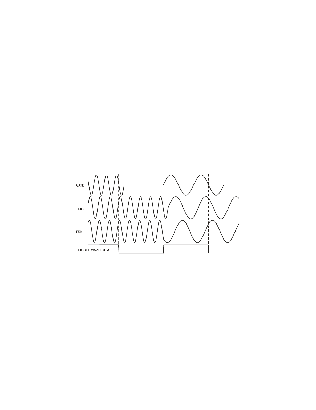
Tone Mode
Introduction 8
there can be an off period between successive frequencies whilst the gate signal is not
true.
With type set to fsk the frequency changes instantaneously (and phasecontinuously) at each occurrence of the signal edge specified in the source and
slope fields on the TRIGGER IN screen without completing the current waveform
cycle; this is true FSK (frequency shift keying) tone switching.
The maximum recommended tone frequencies and trigger/gate switching frequencies for
the three modes are as follows:
gate Maximum tone frequency 50 kHz;
maximum switching frequency less than lowest tone frequency.
trig Maximum tone frequency 50 kHz;
maximum switching frequency 1 MHz.
fsk Maximum tone frequency 1 MHz;
maximum switching frequency 1 MHz.
The drawings below demonstrate the differences between trigger, gate and FSK tone
switching for a list of 2 frequencies switched by a square wave (positive slope specified
on the TRIGGER IN set-up).
Figure 8-1. Tone Waveform Types
shc0007f.emf
Tone Switching Source
The signal which controls the frequency switching is that set by the source soft key
on the TRIGGER IN set-up screen. The slope field on the same screen sets the
active polarity of that signal; when set to positive the rising edge of the trigger
signal is active or the high level of the gating signal is true, and the opposite for a
negative setting. The signal selections on the source soft key are the internal trigger
generator, an external trigger input, the front panel MAN TRIG key, a remote command
or (in the case of multi-channel instruments) the trigger out from an adjacent channel. A
full explanation for each of these can be found in chapter 7, Triggered Burst and Gate.
DTMF Testing With Two Sources
An important use of tone mode is DTMF (Dual Tone Multiple Frequency) testing in
which two channels are set up with equal length lists of different frequencies, triggered
from a common signal. The outputs are summed together using the internal sum facility
(see chapter 12, Sum). DTMF testing generally uses sine waves in the frequency range
600 Hz to 1.6 kHz.
8-3
Find Quality Products Online at: [email protected]
www.GlobalTestSupply.com
Page 59

291, 292, 294
Users Manual
It is also possible to set up DTMF testing using two single channel instruments triggered
by a common external signal and summed using the external SUM capability.
8-4
Find Quality Products Online at: [email protected]
www.GlobalTestSupply.com
Page 60

Chapter 9
Arbitrary Waveform Generation
Title Page
Introduction........................................................................................................ 9-2
Arbitrary Waveform Terms........................................................................... 9-2
Principles of Arbitrary Waveform Creation and Modification...................... 9-2
Selecting and Outputting Arbitrary Waveforms................................................ 9-3
Creating New Waveforms............................................................................. 9-4
Create Blank Waveform............................................................................ 9-4
Create Waveform Copy............................................................................. 9-4
Modifying Arbitrary Waveforms................................................................... 9-5
Resize Waveform...................................................................................... 9-5
Rename Waveform.................................................................................... 9-6
Waveform Info.......................................................................................... 9-6
Delete Waveform...................................................................................... 9-6
Edit Waveform.......................................................................................... 9-7
Point Edit................................................................................................... 9-7
Line Edit.................................................................................................... 9-7
Wave Insert ............................................................................................... 9-8
Block Copy ............................................................................................... 9-8
Waveform Amplitude................................................................................ 9-9
Waveform Offset....................................................................................... 9-10
Wave Invert............................................................................................... 9-10
Position Markers ....................................................................................... 9-10
Arbitrary Waveform Sequence.......................................................................... 9-11
Sequence Set-Up ........................................................................................... 9-12
Frequency and Amplitude Control with Arbitrary Waveforms......................... 9-13
Frequency...................................................................................................... 9-13
Amplitude...................................................................................................... 9-15
Sync Out Settings with Arbitrary Waveforms................................................... 9-15
Waveform Hold in Arbitrary Mode................................................................... 9-15
Output Filter Setting .......................................................................................... 9-16
9-1
Find Quality Products Online at: [email protected]
www.GlobalTestSupply.com
Page 61

291, 292, 294
Users Manual
Introduction
Arbitrary (arb) waveforms are generated by sequentially addressing the RAM containing
the waveform data with the arbitrary clock. The frequency of the arb waveform is
determined both by the arb clock and the total number of data points in the cycle.
In this instrument an arb waveform can have up t
vertical range is -2048 to +2047, corresponding to a maximum peak-to-peak output of
20 Volts. Up to 500 waveforms can be stored on the memory card and each given a
name; the number that can be stored depends on the number of points in each waveform
and the size of the memory card.
Arb waveforms can be created using basic front panel editing capabilities (particularly
useful for modifying existing standard or arb waveforms) or by using waveform design
software that enables the user to create waveforms from mathematical expressions, from
combinations of other waveforms, or freehand; details are given in appendix E.
Arbitrary Waveform Terms
The following terms are used in describing arb waveforms:
Horizontal size: The number of horizontal points is the time component of the
Waveform address: Each horizontal point on an arb waveform
Arb frequency: The arb frequency is the clock rate of the data RAM a
Waveform frequency: The waveform
o 1,048,576 horizontal points. The
waveform
1,048,576 points.
Addresses always start at 0000, thus the end address is always
one less than the horizontal size.
counters and has a range of 0·1 Hz to 100 MHz (internal clock)
or dc to 50 MHz (external clock) on this instrument.
horizontal size. For example a 1000 point waveform clocked at
an arb frequency of 100 MHz has a waveform frequency of
100e6 divided by 1000 = 100 kHz.
. The minimum size is 8 points and the maximum is
has a unique address.
ddress
frequency depends on both the arb frequency and
9-2
Data value: Each point in the waveform has an am
-2048 to +2047.
Waveform amplitude: When playing arb waveforms the
will depend on both the range of data values and the output
amplitude setting. A waveform which includes data values of
-2048 and +2047 will produce a maximum output which is
100 % of the programmed peak-to-peak amplitude; if the
maximum range of the data values is only -1024 to +1023, for
example, the maximum output will only be 50% of the
programmed level.
Principles of Arbitrary Waveform Creation and Modification
Creating arb waveforms with the instrument alone consists of two main steps:
1. Creating a new blank waveform, or a copy of an existing one, and giving it a size and
a na
me
2. Modifying that waveform using the vari
waveform required.
ous editing capabilities to get exactly the
maximum output amplitude
plitude value in the range
Find Quality Products Online at: [email protected]
www.GlobalTestSupply.com
Page 62
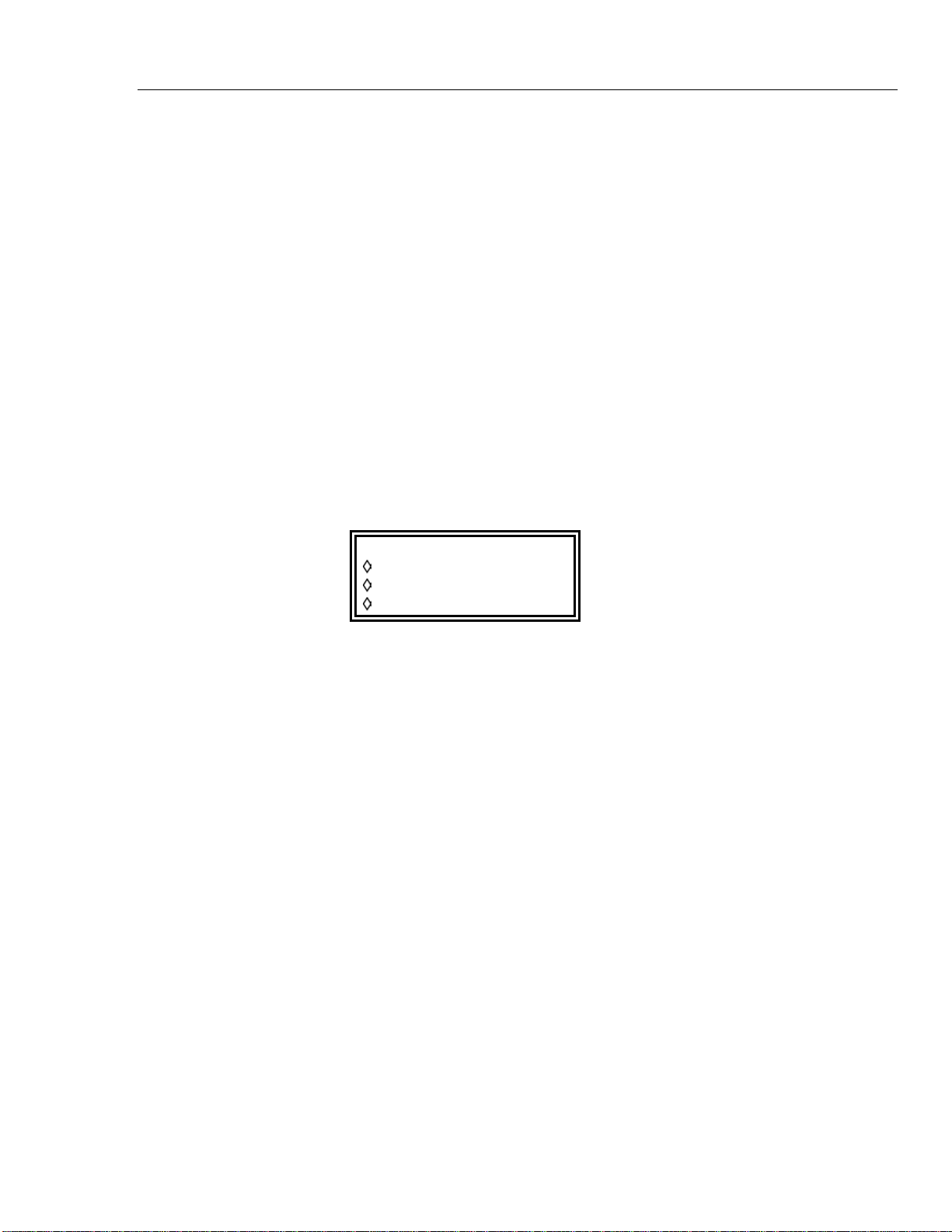
Arbitrary Waveform Generation
These steps are fully described in the Creating New Waveforms and Modifying Arbitrary
Waveforms sections which follow.
Waveform creation using waveform design software also consists of two steps:
1. Creating the waveform using the software on a PC.
2. Downloading the waveform directly to the memory card (using the USB-connected
card reader/writer) and inserting the card into the instrument. Alternatively, the
waveform can be downloaded to the generator via the RS232, GPIB or USB
interfaces. This process is described in chapter 14 and Appendix E.
Modification of an arb waveform that is currently running on the instrument is subject to
certain constraints; these are mentioned in the appropriate individual sections and
warning or error messages will be given if illegal operations are attempted. As a general
rule, modification of a current waveform should only be implemented with the generator
running in continuous mode.
Selecting and Outputting Arbitrary Waveforms 9
Selecting and Outputting Arbitrary Waveforms
With a memory card plugged in, press the ARB key to see the list of all the arbitrary
waveforms held on the card.
ARBITRARY WAVEFORMS
WFM1 4096
WFM2 11000
SPIKE100 100000
If no card is fitted the display will show the message
Please insert a memory card.
If there are no waveforms on the card the message will be
There are no arb waveforms available.
If the generator is switched on without a card fitted, and the power-on conditions have
been set to recall power-down set-up which included an arb waveform, an error message
File <name> not found, load std square
is temporarily displayed and the generator defaults to a square wave output.
With a card plugged in the rotary knob or cursor keys can be used to scroll the full list
backwards and forwards through the display. Select the required waveform by pressing
the associated soft key.
To make it easier to find a particular waveform in a long list it is recommended that the
waveforms on the card are first sorted into alphabetical order using the sort facility on the
MEMORY CARD screen accessed from the UTILITY menu (refer to chapter 14
Memory Card).
Note that the last used arb waveform can also be selected to run from the
STANDARD WAVEFORMS screen, accessed by pressing the STD key, by pressing the
arb soft key in the STANDARD WAVEFORMS list; this makes it easier to switch
quickly between a true standard waveform (e.g. sine) and a particular arb.
9-3
Find Quality Products Online at: [email protected]
www.GlobalTestSupply.com
Page 63
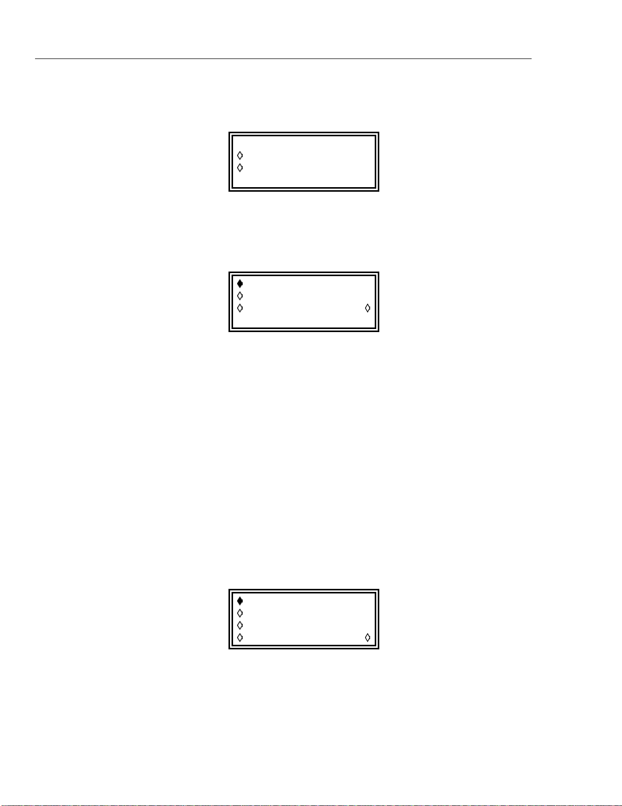
291, 292, 294
Users Manual
Creating New Waveforms
Create Blank Waveform
Pressing the CREATE key calls the CREATE NEW WAVEFORM screen.
CREATE NEW WAVEFORM
create blank…
create from copy…
Pressing the create blank… soft key calls the menu:
create: "WFM1 "
size: 0001024
cancel create
The top line contains the user-defined waveform name which can be up to 8 characters
long. The instrument allocates a default name of WFM<n>) starting at WFM1; the name
can be edited by selecting the appropriate character position with the cursor keys and then
setting the character with the rotary control which scrolls through all alphanumeric
characters in sequence.
Pressing the size soft key permits the waveform length to be entered directly from the
keyboard or by using the rotary control and cursor keys; the default size is 1024. The
minimum size is 8 and the maximum 1,048,576; appropriate warnings are given if
attempts are made to set a waveform size outside these limits.
This menu can be exited either by pressing the cancel soft key which keeps the name
but does not allocate the memory space, or by pressing the create soft key which
builds a “blank” waveform (i.e. one in which all the data values are zero) and returns the
screen to the ARBITRARY WAVEFORMS list.
Create Waveform Copy
Pressing the create from copy... soft key calls the following menu:
create: "WFM1 "
from: sine
size: 0001024
cancel create
The user-defined name and waveform size can be entered after pressing the create
and size soft keys respectively, exactly as described in the previous section.
The source waveform which is to be copied can be selected by the from soft key;
repeated presses of the soft key, cursor keys or using the rotary control will scroll through
the list of all the available waveforms, including any other arbitrary waveforms already
created.
9-4
Find Quality Products Online at: [email protected]
www.GlobalTestSupply.com
Page 64
Arbitrary Waveform Generation
The horizontal size of the waveform being copied does not have to be the same as the
waveform being created. When the waveform is copied, by pressing the create soft
key, the software compresses or expands the source waveform to create the copy. When
the source is expanded the copy has additional interpolated points; when the source is
compressed, significant waveform data may be lost, particularly from arb waveforms
with narrow spikes if the compression ratio is large.
The menu can be exited by pressing the cancel soft key, which keeps the name but
does not implement the copy, or by pressing the create soft key, which makes the
copy and returns the screen to the ARBITRARY WAVEFORMS list.
Modifying Arbitrary Waveforms
Pressing the MODIFY front panel key calls the MODIFY screen.
MODIFY: WFM1
resize… rename…
delete… info…
edit wfm…
Selecting and Outputting Arbitrary Waveforms 9
This screen gives access to a number of menus which permit the selected waveform to be
resized, renamed, edited, etc. The arb waveform to be modified is selected using the
rotary control or cursor keys to step through all possible choices; the current selection is
displayed on the top line beside MODIFY.
Resize Waveform
Pressing the resize… soft key on the MODIFY screen calls the Resize screen.
Resize changes the number of points in the waveform; the new size can be larger or
smaller than the old size. When the new size is larger, the software adds additional
interpolated points. When the size is smaller, points are removed. Reducing the
waveform size may cause the waveform to lose significant data.
Enter the size required by pressing the new size soft key followed by direct entries
from the keyboard or by using the rotary control. Resize is implemented by pressing the
resize soft key or aborted by pressing the cancel soft key; both return the display
to the MODIFY screen. There is no "undo" facility for resize.
Resize: WFM11
(old size: 0016000)
new size: 0
cancel resize
001024
9-5
Find Quality Products Online at: [email protected]
www.GlobalTestSupply.com
Page 65
291, 292, 294
Users Manual
Rename Waveform
Waveform Info
Pressing the rename… soft key on the MODIFY screen calls the Rename screen:
Rename: WFM1
as: "WFM2 "
cancel rename
The new name can be entered below the original by selecting the appropriate character
position with the cursor keys and then setting the character with the rotary control which
scrolls through all the alphanumeric characters in sequence. The name can be up to 8
characters long.
Return to the MODIFY screen by pressing rename (which implements the new
name) or cancel.
Pressing the info… soft key on the MODIFY screen calls the info screen.
The screen gives the name of the waveform, its length and the channels (in multi-channel
versions of the generator) and sequences where it is used.
Pressing exit returns the display to the MODIFY screen.
Delete Waveform
Pressing the delete… soft key displays a request for confirmation that the selected
waveform is to be deleted from the memory card:
Info WFM1 exit
length: 1024
chan:
seq:
Delete waveform
"WFM1 "
?
cancel delete
Confirm deletion by pressing the delete soft key which will return the display to the
MODIFY screen with the next arb waveform automatically selected; cancel aborts
the deletion.
9-6
Find Quality Products Online at: [email protected]
www.GlobalTestSupply.com
Page 66
Arbitrary Waveform Generation
Edit Waveform
Pressing the edit wfm… soft key calls the EDIT FUNCTIONS menu:
EDIT FUNCTIONS:
point edit…
line draw…
wave insert…
This menu provides functions which permit the waveform to be edited point-by-point
(point edit), by drawing lines between two points (line draw) or by inserting all
or part of an existing waveform into the waveform being edited (wave insert). In
addition, sections of the waveform can be selected and their peak-to-peak level changed
using wave amplitude, or baseline changed using wave offset. Sections of the waveform
can be copied into itself (block copy) and position markers for use at SYNC OUT can
also be defined.
Pressing the exit soft key on any of these edit screens will return the display to the
EDIT FUNCTIONS menu.
Selecting and Outputting Arbitrary Waveforms 9
Point Edit
Press the point edit… soft key to call the POINT EDIT screen:
To modify a point, press the addrs soft key and enter the address directly from the
keyboard or by using the rotary control; the current data value will be displayed to the
right of the address. To change the value press value and enter the new value directly
from keyboard or by using the rotary control. Changing the data value automatically
updates the waveform.
Pressing the next point soft key automatically advances the address by one point;
alternatively press addrs to permit address entry from the keyboard or using the rotary
control.
Line Edit
Press the line draw… soft key to call the LINE screen:
POINT EDIT WFM1
(addrs , value)
(0000512, +0500)
exit next point
LINE( addrs ,value)
frm(0000512,+0000)
to (0000750,+0412)
exit draw line
The display shows a frm (from) and to address which will be the points between
which a straight line will be created when the draw line soft key is pressed. The
9-7
Find Quality Products Online at: [email protected]
www.GlobalTestSupply.com
Page 67
291, 292, 294
Users Manual
Wave Insert
default frm address is the first point on the waveform or the point most recently edited
if point edit has been used. Set the from address and value by pressing the
appropriate soft key and making an entry direct from the keyboard or by using the rotary
control; repeat for the to address and value.
The line will be drawn between the two selected points when the draw line soft key
is pressed.
Pressing wave insert… calls the wave insert screen:
WFM1 WFM2
000000 strt0000400
000512 stop0100000
exit insert
Wave insert places waveforms between programmable start and stop points. Both
standard and arbitrary waveforms can be inserted in the new waveform, with the
exception of pulse, pulse-train and sequence.
A section of an arbitrary waveform can be inserted, as defined by the left hand strt
(start) and stop addresses (0 and 512 of WFM1 on the screen above); these addresses
default to the start and stop of the whole waveform but can be reset to define any section
of the waveform. Change the addresses by pressing the appropriate soft key and making
entries from the keyboard or using the rotary control. The destination of the selected
section of the source waveform in the new waveform is defined by the right hand strt
(start) and stop addresses. Change the addresses by pressing the appropriate soft key and
making entries from the keyboard or using the rotary control.
The insertion is confirmed by pressing the insert soft key. If there is a size
difference between the two sections of waveform then the software will expand or
compress the source to fit the new waveform. Compressing the waveform can cause
some significant data to be lost.
To insert sections of the current waveform into itself, see Block Copy
Block Copy
Pressing block copy… calls the BLOCK COPY screen:
BLOCK COPY: WFM42
start:0000400
stop: 0001000 copy
dest: 0000000 exit
Block copy allows a section of the current waveform to be inserted within itself. The
block to be inserted is defined by the start and stop addresses. Change the
addresses by pressing the appropriate soft key and making entries from the keyboard or
using the rotary control.
The destination address for the start of the section is set by pressing the dest soft key
and entering the address.
9-8
Find Quality Products Online at: [email protected]
www.GlobalTestSupply.com
Page 68
Arbitrary Waveform Generation
Press copy to implement the copy. During the two stage block copy process the screen
displays the message processing file - please wait and shows a progress
bar. During the first stage the block to be copied is created as a temporary file with the
same name as the main file but with a $$$ extension; during the second stage the
appropriate section of the original file is overwritten and the temporary file is deleted.
Note that if there are not enough waveform points between the destination address and
end of waveform to accommodate the copied section, the waveform being copied will
simply be truncated. Once copied there is no undo and the original waveform cannot be
recovered.
Block copy edit operates on the version of the waveform in the channel currently selected
by the channel set-up keys; the effect of the edit can be seen by selecting the waveform to
run on that channel. When the block copy is as required it can be saved by pressing the
save soft-key; the action of saving modifies the waveform in the backup memory and
then any other copies of the waveform in other channel memories. Once saved the
original waveform cannot be recovered.
Pressing exit returns to the EDIT FUNCTIONS screen without change.
Waveform Amplitude
Pressing the wave amplitude soft key initiates the creation of a temporary copy of
the waveform to be edited and calls the AMPLITUDE screen:
Selecting and Outputting Arbitrary Waveforms 9
AMPLITUDE: 001·00
0000000 to 0000123
undo set ampl
save & exit save
The waveform amplitude can be changed on a section of the waveform defined by the
start and stop addresses. Set the addresses by pressing the appropriate soft key
and making entries directly from the keyboard or using the rotary control.
The data values over the specified section of the waveform can be multiplied by a factor
of between 0·01 and 100·0 by making entries in the AMPLITUDE field. Press the
appropriate soft key and make entries direct from the keyboard or by using the rotary
control; the amplitude changes on completion of the entry. Note that entries greater
than1·0 will cause clipping if the waveform already uses the full -2048 to +2047 data
value range; the result is, however, still treated as a valid waveform. The original
waveform can be restored by pressing the undo soft key.
Amplitude edit operates on the version of the waveform in the channel currently selected
by the channel set-up keys; the effect of the edit can be seen by selecting the waveform to
run on that channel. When the amplitude has been modified as required the new
waveform can be saved by pressing the save key; once saved the original waveform
cannot be recovered.
Pressing save & exit returns to the EDIT FUNCTIONS screen after the save has
been implemented. To exit the AMPLITUDE edit without saving changes, press undo
then save & exit.
9-9
Find Quality Products Online at: [email protected]
www.GlobalTestSupply.com
Page 69
291, 292, 294
Users Manual
Waveform Offset
Pressing the wave offset soft key initiates the creation of a temporary copy of the
waveform to be edited and calls the WAVE OFFSET screen.
WAVE OFFSET: +0000
0000000 to 0000123
undo set offset
save & exit save
The waveform offset can be changed on a section of the waveform defined by the
start and stop addresses. Set the addresses by pressing the appropriate soft key
and making entries directly from the keyboard or using the rotary control.
The data values over the specified section of the waveform are offset by the value entered
in the WAVE OFFSET field. Press the appropriate soft key and make entries directly
from the keyboard or by using the rotary control. Entries in the range -4096 to +4095
will be accepted; this permits, in the extreme, waveform sections with values at the -2048
limit to be offset to the opposite limit of +2047. Warnings are given when the offset
causes clipping but the entry is still accepted. The original waveform can be restored by
pressing the undo soft key.
Offset edit operates on the version of the waveform in the channel currently selected by
the channel set-up keys; the effect of the edit can be seen by selecting the waveform to
run on that channel. When the offset has been modified as required the new waveform
can be saved by pressing the save key; once saved the original waveform cannot be
recovered.
Pressing save & exit returns to the EDIT FUNCTIONS screen after the save has
been implemented. To exit the WAVE OFFSET edit without saving changes, press
undo then save & exit.
Wave Invert
Pressing the wave invert soft key calls the INVERT screen:
The waveform or a section of it defined by the start and stop addresses can be
inverted. Set the addresses by pressing the appropriate soft key and making entries
directly from the keyboard or using the rotary control.
The data values over the specified section of the waveform are inverted about 0000 each
time the invert soft key is pressed.
INVERT: WFM1
start adrs: 0000512
stop adrs: 0000750
exit invert
Press exit to return to the EDIT FUNCTIONS screen.
Position Markers
Pressing the position markers… soft key calls the POSITION MARKER EDIT
screen:
9-10
Find Quality Products Online at: [email protected]
www.GlobalTestSupply.com
Page 70
Arbitrary Waveform Generation
POSITION MARKER EDIT
adrs: 0000000 <0>
patterns…
exit clear all
Position markers are output from SYNC OUT when the source (src) is set to
pos’n marker on the SYNC OUTPUT SETUP screen.
Position markers can be set at any or all of the addresses of a waveform either
individually, using the adrs (address) soft key, or as a pattern, using the patterns…
menu.
A marker can be set directly at an address by pressing the adrs soft key followed by a
keyboard entry; pressing the right-hand soft key on the adrs line then toggles the
marker setting between <1> and <0> as shown in the arrowed brackets. The address
can be changed by incrementing with the adrs key, by using the rotary control, or by
further keyboard entries; marker settings are changed at each new address with the righthand soft key. Markers show immediately they are changed.
Arbitrary Waveform Sequence 9
Alternatively, markers can be input as patterns by using the patterns… sub-menu:
PATTERN: 0
start: 0000000
stop: 0001023
exit: do pattern
The start and stop addresses of the markers within the waveform are set using the
start and stop soft keys respectively, followed by an entry on the keyboard or by
using the rotary control.
The pattern itself is set in the top line of the display; press the soft key to the right of
PATTERN: and enter the sequence of 1s and 0s using 1 and 0 from the keyboard
(which auto-increments to the next character) or with the rotary control (using the cursor
keys to move the edit cursor along the pattern). The pattern consists of 16 values; if the
cursor keys are used to skip over some character positions these will automatically be
filled with the value of the last digit specified to the left. The pattern is entered
repeatedly across the whole range defined by the start and stop addresses when
the do pattern soft key is pressed; pressing exit returns to the
POSITION MARKER EDIT screen without implementing the pattern.
Pressing the clear all soft key displays a request for confirmation that all markers
should be cleared from the waveform. Pressing clear cancels all the markers and
returns the display to POSITION MARKER EDIT ; pressing cancel aborts the
clear.
0000000…
Arbitrary Waveform Sequence
Up to 1024 arbitrary waveforms may be linked in a sequence provided that the total
number of points of all the waveforms in the sequence does not exceed 1,048,576. Each
waveform can have a loop count of up to 32,768 and the whole sequence can run
continuously or be looped up to 1,048,575 times using the triggered burst mode.
9-11
Find Quality Products Online at: [email protected]
www.GlobalTestSupply.com
Page 71
291, 292, 294
Users Manual
Sequence Set-Up
Pressing the SEQUENCE key calls the initial SEQUENCE screen:
SEQUENCE segs= 1
sequence setup…
stop run
A previously-defined sequence can be run and stopped from this screen using the run
and stop soft keys; sequence can also be switched on from the
STANDARD WAVEFORMS screen with the sequence soft key. The segs= field
shows the number of segments in the sequence; there is always at least 1 segment.
Pressing the sequence setup… soft key on the SEQUENCE screen (or the
setup… soft key next to sequence on the STANDARD WAVEFORMS screen) calls the
sequence set up screen:
seg: 0002 off
wfm WFM3
step on: count
cnt: 00001 done
Repeated presses of the seg soft key steps the display through the set-ups of each of
the 1024 segments of the sequence. With the exception of segment 1 which is always on
(and therefore has no on-off soft key) the segment set-ups are identical in format. When
segment 1 is displayed the segs= field shows the total number of segments in the
current sequence.
The segment to be set up is selected with the seg soft key; the segments can be
selected in sequence with repeated presses of the soft key, by using the rotary control or
by numeric entry.
Once the segment to be edited has been set the waveform for that segment is selected
with the wfm (waveform) soft key; the list of all arbitrary waveforms already created is
stepped through with repeated presses of the wfm soft key or by using the rotary
control.
The criterion for stepping between waveform segments is set by the step on soft key.
The default setting is step on: count which means that the waveform will step on
to the next segment after the number of waveform cycles specified in the cnt (count)
field; up to 32,768 cycles can be set with cnt selected, using direct keyboard entries or
using the rotary control.
Alternatively, the step on criteria can be set to trig edge or trig level in the
step on field; trigger edge or trigger level can be mixed with count (i.e. some
segments can step on count, others on the specified trigger condition) but trigger edge
cannot be mixed with trigger level in the same sequence.
If trig edge is selected the sequence starts running at the first waveform segment
when sequence is set to run and steps to the following segments in turn at each
subsequent trigger. The trigger source can be any of the settings selected on the
TRIGGER IN set-up screen (called by the TRIG IN key); these are described fully in
9-12
Find Quality Products Online at: [email protected]
www.GlobalTestSupply.com
Page 72
Arbitrary Waveform Generation
chapter 7, Triggered Burst and Gate. At each trigger the current waveform cycle plus
one further whole cycle are completed before the waveform of the next segment is
started.
If trig level is selected the sequence runs continuously through each segment in
turn (one cycle per segment) while the trigger level is true. When the trigger level goes
false the waveform currently selected runs continuously until the level goes true again, at
which point the sequence runs continuously through each segment in turn again. The
trigger level source can be any of the settings selected on the TRIGGER IN set-up
screen with the exception of the MAN TRIG key which can only produce an edge, not a
level, when pressed.
Providing the step on: field is set to count for all segments the waveform
sequence can also be run in gated and triggered burst modes in the same way as simple
waveforms; refer to chapter 7, Triggered Burst and Gate, for full details.
The individual segments of the sequence can be turned on or off with the on−off soft
key. Note that turning a segment off will automatically set all subsequent segments off;
turning a segment on will also turn on any others between segment 1 and itself that were
previously off. Segment 1 is always on.
When the whole sequence is defined the set-up is constructed by pressing the done soft
key which returns the display to the initial SEQUENCE screen. The sequence can be
run and stopped from this screen with the run and stop soft keys respectively.
Frequency and Amplitude Control with Arbitrary Waveforms 9
Frequency and Amplitude Control with Arbitrary Waveforms
Frequency and amplitude control work in an essentially similar manner as with standard
waveforms; the differences are as follows:
Frequency
Pressing the FREQuency key with an arbitrary waveform selected calls the
ARBITRARY FREQUENCY screen:
ARB FREQUENCY: int
100·00000 MHz
sample waveform
freq period
Arbitrary mode uses clock synthesis generation (see Principles of Operation in chapter 4,
Initial Operation) which has a setting resolution of only 8 digits. However, the clock can
also be provided from an external source via the rear panel ARB CLOCK IN/OUT
socket or, on multi-channel instruments, the system clock. The clock source switches
between internal and external clock with alternate presses of the ARB FREQUENCY
soft key. When external clock is selected the ARB FREQUENCY screen changes to:
ARB FREQUENCY: ext
source: ext arb clk
9-13
Find Quality Products Online at: [email protected]
www.GlobalTestSupply.com
Page 73
291, 292, 294
Users Manual
on a single channel instrument, or
ARB FREQUENCY: ext
source: ext arb clk
freq: 10.0000000kHz
on a multi-channel instrument. It is then possible to select the source to be either an
external signal on the ARB CLOCK IN/OUT socket or the internal system clock; see the
Reference Clock IN/OUT and System Clock Setting sections of Chapter 15, System
Operations from the Utility Menu for the use of and frequency setting for the system
clock.
Note that SEQUENCE and the ‘standard’ waveforms of square, pulse and pulse-train
also operate in clock synthesis mode and consequently can also be set to external clock
on the appropriate FREQUENCY menus; refer to the relevant sections for further details.
Having selected external clock the arbitrary waveform will continue to run from the
internal clock until the instrument receives the first rising edge of the external clock; at
that point the hardware switches over to the external source.
The following applies only to internal clock selection.
Frequency can be set in terms of frequency or period, as for standard waveforms, by
pressing the freq or period soft key respectively. Additionally, for arbitrary
waveforms, frequency or period can be set in terms of the sample clock frequency, by
pressing the sample soft key, or in terms of the waveform frequency, by pressing the
waveform soft key. The relationship between them is:
waveform frequency = sample frequency ÷ waveform size.
Frequency and period entries are made directly from the keyboard or by using the rotary
control in the usual way. Pressing the FREQuency key with sequence running calls the
SEQ FREQUENCY screen:
SEQ FREQUENCY: int
100·00 MHz
freq period
With internal clock selected (the default), frequency or period can now only be set in
terms of the clock frequency. Frequency or period entries are made directly from the
keyboard or by using the rotary control in the usual way.
With external clock selected using the SEQ FREQUENCY soft key the sequence can
be clocked using an external source connected to the rear panel ARB CLOCK IN/OUT
socket.
9-14
Find Quality Products Online at: [email protected]
www.GlobalTestSupply.com
Page 74
Arbitrary Waveform Generation
Amplitude
Pressing the AMPLitude key with an arbitrary waveform selected calls the AMPLITUDE
screen.
This differs from the AMPLITUDE screen for standard waveforms in that amplitude can
now onl
AMPLITUDE:
+20·0 Vpp
Vpp
load:hiZ
y be entered in volts peak-to-peak.
Sync Out Settings with Arbitrary Waveforms 9
Note that the peak-to-peak amplitude set will onl
waveform has addresses with values which reach -2048 and +2047; if the maximum
value range is -1024 to +1023 for example then the maximum peak-to-peak voltage will
only be 10 V p-p for the instrument set to 20 V p-p.
y actually be output if the arbitrary
Sync Out Settings with Arbitrary Waveforms
The default setting for sync out when arbitrary waveforms are selected is
waveform sync; this is a pulse that starts coincident with the first point of the
waveform
If a waveform sequence has been selected then s
this is a waveform
sequence and is high at all other times. When sequence is used in triggered burst mode
the burst count is a count of the number of complete sequences.
and is a few points wide.
ync out defaults to sequence sync;
which goes low during the last cycle of the last waveform in a
Waveform Hold in Arbitrary Mode
Arbitrary waveforms can be paused and restarted by using the front panel MAN HOLD
key or by a signal applied to the rear panel HOLD IN socket.
On multi-channel instruments the channels which are to be held by the MAN HOLD key
or HOLD IN socket must first be enabled using the ARB HOLD INPUT screen,
acc
essed by pressing the HOLD key:
ARB HOLD INPUT:
status no hold
mode: disabled
Each channel is selected in turn using th
soft-key; the mode changes between disabled and enabled with alternate key
presses.
Pressing the front panel MAN HOLD key stops the waveform at the current level on all
enabled channels; pressing MAN HOLD a second time restarts the waveform from that
level. If the ARB HOLD INPUT screen is currently selected the status field will
change from no hold to manual hold while the waveform is paused.
9-15
Find Quality Products Online at: [email protected]
www.GlobalTestSupply.com
e channel set-up keys and set using the mode
Page 75
291, 292, 294
Users Manual
Output Filter Setting
The output filter type is automatically chosen by the software to give the best signal
quality for the selected waveform. The choice can, however, be overridden by the user
and this is most probably a requirement with arbitrary waveforms.
To change the filter, press the FILTER key to call the FILTER SETUP screen:
FILTER SETUP
mode: auto
type: 40MHz eliptic
The default mode is auto which means that the software selects the most appropriate
filter. With the setting on auto the type can be changed manually but the choice will
revert to the automatic selection as soon as any relevant parameter is changed. To
override the automatic choice press the mode soft key to select manual.
The three filter choices, which are either automatically selected or set manually with the
type soft key, are as follows:
40MHz elliptic: The automatic choice for sine, cosine, haversine, havercosine, sin(x)/x
and triangle. Would be the better choice for arb waveforms with an
essentially sinusoidal content.
20MHz Bessel: The automatic choice for positive and negative ramps, arb and
sequence.
No filter: The automatic choice for square wave, pulses and pulse-trains. May
be the better choice for arb waveforms with an essentially rectangular
content.
9-16
Find Quality Products Online at: [email protected]
www.GlobalTestSupply.com
Page 76

Chapter 10
Pulse and Pulse-trains
Title Page
Introduction........................................................................................................ 10-2
Pulse Set-Up ...................................................................................................... 10-2
Pulse-Train Set-Up ............................................................................................ 10-4
Waveform Hold in Pulse and Pulse-Train Modes ............................................. 10-8
10-1
Find Quality Products Online at: [email protected]
www.GlobalTestSupply.com
Page 77
291, 292, 294
Users Manual
Introduction
Pulse Set-Up
Pulse and pulse-trains are both selected and set-up from independent menus on the
STANDARD WAVEFORMS screen called by pressing the STD key. Pulse and pulse-
trains have similar timing set-ups and considerations but pulses are only unipolar, with a
maximum amplitude of 10 V p-p, whereas pulse-trains can be bipolar, with a maximum
peak-to-peak of 20 V p-p.
Pulse waveforms are turned on with the pulse soft key on the
STANDARD WAVEFORMS screen; pressing the setup… soft key beside pulse
calls the first of the pulse set-up screens:
Enter pulse period:
100·00000 us
10000pts*10.000000ns
exit next
The third line of the screen indicates how the waveform will be constructed; in this case it
will be 10000 points played back at a clock period of 10.000000ns to give a period of
10000x10
-9
= 100µs. These values will change as the period is varied. The clock period
will determine the resolution available for setting the delay and width as discussed below.
The pulse period can be set between 40·000000 ns and 100.00000 s, with 4−digit
resolution, by direct entries from the keyboard or by using the rotary control. Pressing the
next soft key calls the pulse width screen:
Enter pulse width:
program 50·000000 us
actual 50·000000 us
exit next
The width can be entered directly from the keyboard or by using the rotary control. Any
value in the range 10·00000 ns to 99·999999 s can be programmed but the actual value
may differ because of the considerations discussed below; for this reason the actual pulse
width is shown below the program width.
Pressing the next soft key calls the pulse delay screen:
Enter pulse delay:
program+0·0000000 ns
actual +0·0000000 ns
exit done
This is very similar to the pulse width screen and, again, the actual delay is shown
below the program delay. The delay value that can be entered must be in the range
± (pulse period -1 point); positive values delay the pulse output with respect to waveform
sync from SYNC OUT; negative values cause the pulse to be output before the
10-2
Find Quality Products Online at: [email protected]
www.GlobalTestSupply.com
Page 78
Pulse and Pulse-trains
waveform sync. Pressing the done soft key on this screen returns the display to the
STANDARD WAVEFORMS screen.
The means by which pulse period is set-up in the hardware requires an understanding
because it affects the setting resolution of both pulse width and delay. Pulse is actually a
particular form of arbitrary waveform made up of between 4 and 100,000 points; each
point has a minimum duration of 10·000000 nscorresponding to the fastest clock
frequency of 100 MHz.
At short pulse periods, i.e. only a few points in the waveform, the period setting
resolution is, however, much better than 10·000000 ns because the time-per-point is
adjusted as well as the number of points; since the pulse width and delay are also defined
in terms of the same point time, varying the time-per-point affects their resolution. For
example, if the period is set to 200.00000 ns, the minimum pulse width, when set to
10·000000 ns, will actually be 10·000000 ns; 20 points at 10·000000 ns each exactly
define the 200.00000 ns period. However, if the period is set to 199·00000 ns, 20 points
at the minimum point time of 10·000000 ns will be too long so 19 points are used and the
point time is adjusted to 10.473684 ns (199·0÷19); 10.473654 ns is now the increment
size used when changing the pulse width and delay.
For periods above 1 ms the maximum number of points in the waveform (100,000)
becomes the factor determining pulse width and delay resolution. For example, with the
period set to 100 ms, the smallest pulse width and delay increment is 1 µs
(100 ms÷100,000). This may appear to cause significant errors at extreme settings (e.g.
setting 10 ns in the above example will still give an actual width of 1 µs) but in practical
terms a 1 in 100,000 resolution (0·001 %) is quite acceptable.
Pulse Set-Up10
Pulse period can be adjusted irrespective of the pulse width and delay setting (for
example, it can be set smaller than the programmed pulse width) because, unlike a
conventional pulse generator, pulse width and delay are adjusted proportionally as the
period is changed. For example, if, from the default pulse settings of 100 µs period and
50 µs width, the period is changed to 60 µs the pulse width actual changes to 30 µs
even though the program width is still 50 µs; to get a 50 µs width with the period at
60 µs the width must be re-entered as 50 µs after the period has been changed.
Period can also be changed from the PULSE PERIOD screen called by pressing the
FREQ key with pulse mode selected.
PULSE PERIOD: int
100·00000 us
freq period
The new setting can be entered either as a period in the way already described or as a
frequency by first pressing the freq soft key. However, changing the period or
frequency from this screen is slightly different from changing period on the pulse set-up
screen. When changing from this screen the number of points in the waveform is never
changed (just as with a true arb) which means that the shortest period (highest repetition
frequency) that can be set is the number of waveform points multiplied by 10·00 ns. To
achieve faster frequencies (up to the specification limit) the period must be changed from
the pulse set-up screen; changing the frequency from the pulse set-up screen causes the
number of points to be reduced as the period is reduced (for periods <1ms).
Because pulse waveforms are actually a particular form of arb and use clock synthesis
mode, pulse mode can also be operated with an external clock connected to the rear panel
10-3
Find Quality Products Online at: [email protected]
www.GlobalTestSupply.com
Page 79
291, 292, 294
Users Manual
ARB CLOCK IN/OUT socket, or to the system clock on multi-channel instruments. To
select external clock mode press the PULSE PERIOD soft key on the
PULSE PERIOD screen (or the PULSE FREQ soft key on the PULSE FREQ
screen) to change from internal to external clock. The screen changes to, for example:
PULSE PERIOD: ext
source: ext arb clk
on a single-channel instrument, or
PULSE PERIOD: ext
source: ext arb clk
freq: 10.0000000kHz
on a multi-channel instrument. It is then possible to select the source to be either an
external signal on the ARB CLOCK IN/OUT socket or the internal system clock; see the
Reference Clock IN/OUT and System Clock Setting sections of Chapter 15, System
Operations from the Utility Menu for the use of and frequency setting for the system
clock.
Note that the pulse waveform will continue to run from the internal clock until the
instrument receives the first rising edge of the external clock; at that point the hardware
switches over to the external source. In external clock mode the period of the pulse
waveform is determined by the number of points in the waveform multiplied by the
period of the external clock. The external clock period is determined by the user; the
number of points in the pulse waveform can be found, before selecting external clock,
by pressing the set-up soft key beside pulse on the STANDARD WAVEFORMS screen.
Pulse-Train Set-Up
Pulse-trains are turned on with the pulse-train soft key on the STANDARD WAVEFORMS
screen; pressing the setup… soft key beside pulse-train calls the first of the set-up
screens:
Enter no of pulses
in train (1-10):
2
done next
The number of screens used for the set-up depends on the number of pulses in the pulsetrain. The first three screens define the parameters that apply to the whole pattern
(number of pulses, overall pulse-train period and baseline voltage); subsequent screens
define the pulse level, width and delay for each pulse in turn (three screens for pulse 1,
then three screens for pulse 2, etc.).
10-4
Find Quality Products Online at: [email protected]
www.GlobalTestSupply.com
Page 80
Pulse and Pulse-trains
Pulse-Train Set-Up10
Pressing next on any screen calls the next set-up screen, finally returning the display
to the STANDARD WAVEFORMS screen from which pulse-train can be turned on and
off. Pressing done returns the display directly to the STANDARD WAVEFORMS
screen from any set up screen. The pulse-train is built only after next is pressed after
the last parameter set-up or whenever done is pressed, assuming a change has been
made. The first screen, shown above, sets the number of pulses (1 to 10) in the pattern;
enter the number of pulses directly from the keyboard or by using the rotary control.
Pressing next calls the pulse train period screen:
pulse train period:
1
00.00000us
10000pt*10.000000ns
done next
The third line of the screen indicates how the waveform will be constructed; in this case it
will be 10000 points played back at a clock period of 10.000000ns to give a period of
10000x10
-9
= 100µs. These values will change as the period is varied. The clock period
will determine the resolution available for setting the delay and width as discussed below.
The period can be set, with 8 digit resolution, from 10·000000 ns to 100 s by direct
keyboard entries or by using the rotary control.
Pressing next calls the baseline voltage screen, the last of the general set-up screens:
Enter the baseline
voltage:
+0
·000 V
done next
The baseline is the signal level between the end of one pulse and the start of the next, i.e.
it is the level at which all pulses start and finish. The baseline can be set between -5·0V
and +5·0V by direct keyboard entries or by using the rotary control. Note that the actual
baseline level at the output will only be as set in this field if the output amplitude is set to
maximum (10 V p-p into 50 Ω) on the AMPLITUDE screen and terminated in 50 Ω. If
the amplitude were set, for example, to 5 V p-p into 50 Ω then the actual baseline range
would be -2·5 to +2·5 V for set values of -5·0 to +5·0 V, i.e. the amplitude control scales
the baseline setting. The actual output levels are doubled when the output is not
terminated.
Pressing next on this screen calls the first of the three screens which define the first
pulse in the train:
Pulse 1 level
+5·000 V
done next
10-5
Find Quality Products Online at: [email protected]
www.GlobalTestSupply.com
Page 81
291, 292, 294
Users Manual
The pulse level can be set on this screen between -5·0 V and +5·0 V by direct keyboard
entries or by using the rotary control. As with the baseline level described above the set
pulse levels are only output if the amplitude setting is set to maximum (10 V p-p into
50Ω) on the AMPLITUDE screen and terminated in 50 Ω. Adjusting the amplitude
scales both the peak pulse levels and baseline together, thus keeping the pulse shape in
proportion as the amplitude is changed, exactly as for arb waveforms. Output levels are
doubled when the output is not terminated.
Note that by pressing the Pulse soft key on this (and subsequent screens) the pulse to
be edited can be directly set from the keyboard or by using the rotary control; this is
useful in directly accessing a particular pulse in a long pulse train instead of having to
step through the whole sequence.
Pressing next calls the pulse width screen for the first pulse:
Pulse 1 width
program 25·000000us
•
actual 25·000000us
done next
The width can be entered directly from the keyboard or by using the rotary control. Any
value in the range 10·000000 ns to 99·999999 s can be programmed but the actual value
may differ; for this reason the actual pulse width is shown below the program
width. The variation between program and actual will only really be noticeable
for very short pulse-train periods (only a few points in the pulse-train) and very long
periods (each of the 50,000 points has a long dwell time) for exactly the same reasons as
described in the Pulse Set-up section above, where there is a detailed explanation.
Pressing next calls the pulse delay screen for the first pulse:
Pulse 1 delay
program+0·0000000ns
•
actual +0·0000000ns
done next
The pulse delay is entered in the same way as pulse width and, again, the actual
delay is shown below the program delay for the same reasons. The delay value that
can be entered must be in the range ±(pulse-train period -1 point); positive values delay
the pulse with respect to waveform sync from SYNC OUT; negative values cause the
pulse to be output before the waveform sync.
Pressing next on this screen calls the first of the 3 screens for setting the parameters of
pulse 2, and so on through all the pulses in the pulse-train. In this way all parameters of
all pulses are set. The pulse-train is built when next is pressed on the last screen of
the last pulse or when done is pressed on any screen.
Care must be taken that the set widths and delays of the individual pulses are compatible
with each other and the overall pulse-train period, i.e. delays must not be such that pulses
overlap each other and delays + widths must not exceed the pulse-train period;
unpredictable results will occur if these rules are not followed.
Once the pulse-train has been defined the period can be adjusted irrespective of the pulse
width and delay settings for the individual pulses because, unlike a conventional pulse
10-6
Find Quality Products Online at: [email protected]
www.GlobalTestSupply.com
Page 82
Pulse and Pulse-trains
generator, the individual pulse widths and delays are adjusted proportionally to the period
as the period is changed.
Period can also be changed from the PULSE-TRN PERIOD screen called by pressing
the FREQ key with pulse-train mode selected:
PULS-TRN PER: int
100·00000 us
freq period
The new setting can be entered either as a period in the way already described or as a
frequency by first pressing the freq soft key. However, changing the period or
frequency from this screen is slightly different from changing the period on the pulsetrain set-up screen. When changing from this screen the number of points in the
waveform is never changed (just as with a true arb) which means that the shortest period
(highest frequency) that can be set is the number of waveform points times 10·00 ns. To
achieve faster frequencies (up to the specification limit) the period must be changed from
the pulse-train set-up screen. Changing the frequency from the pulse-train set-up screen
causes the number of points to be reduced as the period is reduced (for periods less than
1·00 ms).
Pulse-Train Set-Up10
Because pulse-train waveforms are actually a particular form of arb and use clock
synthesis mode, pulse-train mode can also be operated with an external clock connected
to the rear panel ARB CLOCK IN/OUT socket or the system clock on multi-channel
instruments. To select external clock mode press the PULS-TRN PER soft key on the
PULS-TRN PER screen (or the PULSE FREQ soft key on the PULSE FREQ
screen) to change from internal to external clock. The screen changes to, for
example:
PULS-TRN PER: ext
source: ext arb clk
on a single channel instrument, or
PULS-TRN PER: ext
source: ext arb clk
freq: 10.0000000kHz
on a multi-channel instrument. It is then possible to select the source to be either an
external signal on the ARB CLOCK IN/OUT socket or the internal system clock; see the
Reference Clock IN/OUT and System Clock Setting sections of Chapter 15, System
Operations from the Utility Menu for the use of and frequency setting for the system
clock.
10-7
Find Quality Products Online at: [email protected]
www.GlobalTestSupply.com
Page 83
291, 292, 294
Users Manual
Waveform Hold in Pulse and Pulse-Train Modes
Note that the pulse-train waveform will continue to run from the internal clock until the
instrument receives the first rising edge of the external clock; at that point the hardware
switches over to the external source. In external clock mode the period of the pulse-train
waveform is determined by the number of points in the waveform multiplied by the
period of the external clock. The external clock period is determined by the user; the
number of points in the pulse-train waveform can be found, before selecting external
clock, by pressing the setup soft key beside pulse-train on the
STANDARD WAVEFORMS screen.
Pulse and pulse-train waveforms can be paused and re-started on any channel by using
the front panel MAN HOLD key or by applying a signal to the rear panel HOLD IN
socket.
On multi-channel instruments the channels which are to be held by the MAN HOLD key
or HOLD IN socket must first be enabled using the ARB HOLD INPUT screen,
accessed by pressing the HOLD key:
ARB HOLD INPUT:
status: no hold
mode: disabled
Each channel is selected in turn using the channel SETUP keys and set using the mode
soft-key. The mode changes between disabled and enabled with alternate key
presses.
Pressing the front panel MAN HOLD key stops the waveform at the current level on all
enabled channels; pressing MAN HOLD a second time restarts the waveform from that
level. If the ARB HOLD INPUT screen is currently selected the status field will
change from no hold to manual hold while the waveform is paused.
A logic low or switch closure at the rear panel HOLD IN socket also stops the waveform
at the current level on all enabled channels; a logic high or switch opening restarts the
waveform from that level. If the ARB HOLD INPUT screen is currently selected the
status field will change from no hold to ext hold while the waveform is
paused.
10-8
Find Quality Products Online at: [email protected]
www.GlobalTestSupply.com
Page 84

Chapter 11
Modulation
Title Page
Introduction........................................................................................................ 11-2
External VCA................................................................................................ 11-2
External SCM................................................................................................ 11-3
Internal Modulation ........................................................................................... 11-3
11-1
Find Quality Products Online at: [email protected]
www.GlobalTestSupply.com
Page 85
291, 292, 294
Users Manual
Introduction
Both internal and external modulation can be selected. External modulation can be
applied to any or all channels. Internal modulation uses the previous channel as the
modulation source, e.g. channel 2 can be used to modulate channel 3; internal modulation
is not available on channel 1 or on a single channel instrument.
The external modulation mode can be set to VCA (voltage controlled amplitude) or SCM
(suppressed carrier modulation) mode. Internal modulation uses the previous channel as
the modulation source; for example channel 2 can be used to modulate channel 3. Thus
internal modulation is not available on channel 1 or on a single channel instrument.
Modulation modes share some of the generator’s inter−channel resources with Sum
modes; as a result there are some restrictions on using Modulation and Sum together but
these are generally outside the range of common−sense applications. To better
understand these constraints the following sections (and the Sum chapter) should be read
with reference to the block diagrams in the Appendix, which show the control signals of a
single channel and the inter−channel connections.
These diagrams also show the inter-channel trigger connections described in the
Triggered Burst and Gate chapter; in general, inter-channel triggering is possible
simultaneously with modulation but few combinations are of real use.
Pressing the MODULATION key calls the MODULATION set-up screen.
The source soft key steps the modulation choice between off, external and CHx
where x is the number of the previous channel; note that channel 1 does not have a
previous channel.
With ext selected the modulation can be switched between VCA and SCM with
alternate presses of the type soft key. External modulation can be used with internal or
external sum. External modulation can be applied to any or all channels.
External VCA
Select VCA with the type soft key on the MODULATION screen. Connect the
modulating signal to the MODULATION socket (nominally 1 kΩ input impedance); a
positive voltage increases the output amplitude and a negative voltage decreases the
amplitude. Note that clipping will occur if the combination of amplitude setting and
VCA signal attempts to drive the output above 20 V p-p open circuit voltage.
External AM is achieved by setting the required output level and applying the modulation
signal (which can be ac coupled if required) at the appropriate level to obtain the
modulation depth required. If the output level is changed the amplitude of the
modulating signal will have to be changed to maintain the same modulation depth.
MODULATION
source: ext
type: VCA
The VCA signal is applied to the amplifier chain prior to the output attenuators. The
amplifier itself is controlled over a limited range (approximately 10 dB) and the full
amplitude range is achieved by switching in up to five 10 dB attenuation stages. Peak
modulation cannot exceed the maximum of the range within which the channel output
has been set by choice of amplitude setting. Whereas with internal AM the generator
11-2
Find Quality Products Online at: [email protected]
www.GlobalTestSupply.com
Page 86
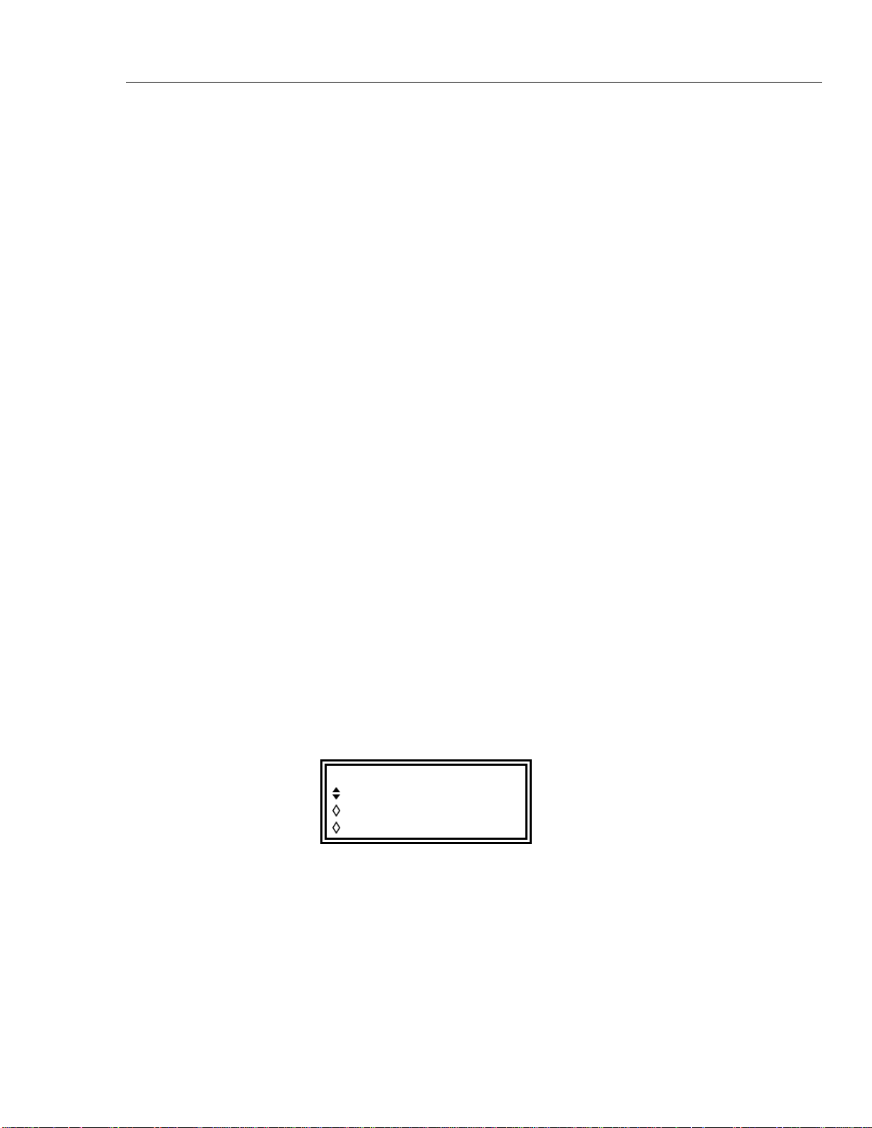
Modulation
gives warnings when the combination of modulation depth and amplitude setting cause
waveform clipping (see Internal Modulation section), it is up to the user to observe the
waveforms when using external VCA and to make adjustments if the waveform is
clipping. Note that it is not possible to give a simple guide as to where the range
breakpoints are because the use of dc offset, for example, changes these points.
Within each range the maximum output setting at which clipping is avoided is reduced
from range maximum to half this value as modulation is increased from 0 % to 100 %;
100 % modulation will be achieved at this mid-range setting with an external VCA signal
of approximately 1 V p-p.
It is also possible to modulate a dc level from the generator with a signal applied to the
MODULATION socket, as follows. Set the generator to external trigger on the
TRIGGER IN set-up screen but do not apply a trigger signal to the TRIG IN socket;
select square wave. The MAIN OUT is now set at the peak positive voltage defined by
the amplitude setting; pressing the ± key with AMPLITUDE displayed will set the level
to the peak negative voltage. This dc level can now be modulated by the signal applied to
the MODULATION input.
External SCM
Select SCM with the type soft key on the MODULATION screen. Connect the
modulating signal to the MODULATION input (nominally 1 kΩ input impedance). With
no signal the carrier is fully suppressed; a positive or negative level change at the
modulation input increases the amplitude of the carrier. Note that clipping will occur if
the SCM signal attempts to drive the output above the 20 V p-p open circuit voltage.
Internal Modulation11
Peak modulation, i.e. maximum carrier amplitude (20 V p-p), is achieved with an
external SCM level of approximately ±1 V, i.e. a 2 V p-p signal.
When external SCM is selected the amplitude control is disabled; the AMPLITUDE
set-up screen shows the message fixed by SCM.
Internal Modulation
Only the multi-channel instruments (models 292 and 294) can make use of internal
modulation; the single-channel model 291 has no internal modulation capability.
Pressing the MODULATION key calls the MODULATION set-up screen.
The source soft-key steps the modulation choice between off, external and
CHx where x is the number of the previous channel.
With CHx selected the modulation can be switched between AM and SCM with
alternate presses of the type soft-key.
MODULATION
source: Ch3
type: SCM
level
When AM is selected the screen has an additional soft-key labeled depth; selecting
this key permits the modulation depth to be set directly from the keyboard or by the
rotary control.
11-3
Find Quality Products Online at: [email protected]
www.GlobalTestSupply.com
Page 87

291, 292, 294
Users Manual
Warnings are given when either a modulation depth or output amplitude change has
caused clipping; the new setting is accepted but it must either be changed back or the
other parameter must also be changed to avoid the contention.
When SCM is selected the screen has an additional soft-ke
y labeled level; selecting
this key permits the peak carrier output level to be set directly from the keyboard or by
the rotary control. The maximum output level that can be set is 10 V p-p.
When internal SCM is selected for a channel bot
h the amplitude control of that channel
and of the previous channel (which is the modulation source) are disabled. The
AMPLITUDE set-up screen of the channel being modulated shows the message
fixed by SCM. The AMPLITUDE screen of the previous channel shows the
sage Set by CHx mod and its status screen shows the message •x to indicate
mes
that it is being used as a source for channel x.
Internal modulation cannot be used with internal or external sum.
11-4
Find Quality Products Online at: [email protected]
www.GlobalTestSupply.com
Page 88

Chapter 12
Sum
Title Page
Introduction........................................................................................................ 12-2
External Sum...................................................................................................... 12-2
Internal Sum....................................................................................................... 12-3
12-1
Find Quality Products Online at: [email protected]
www.GlobalTestSupply.com
Page 89
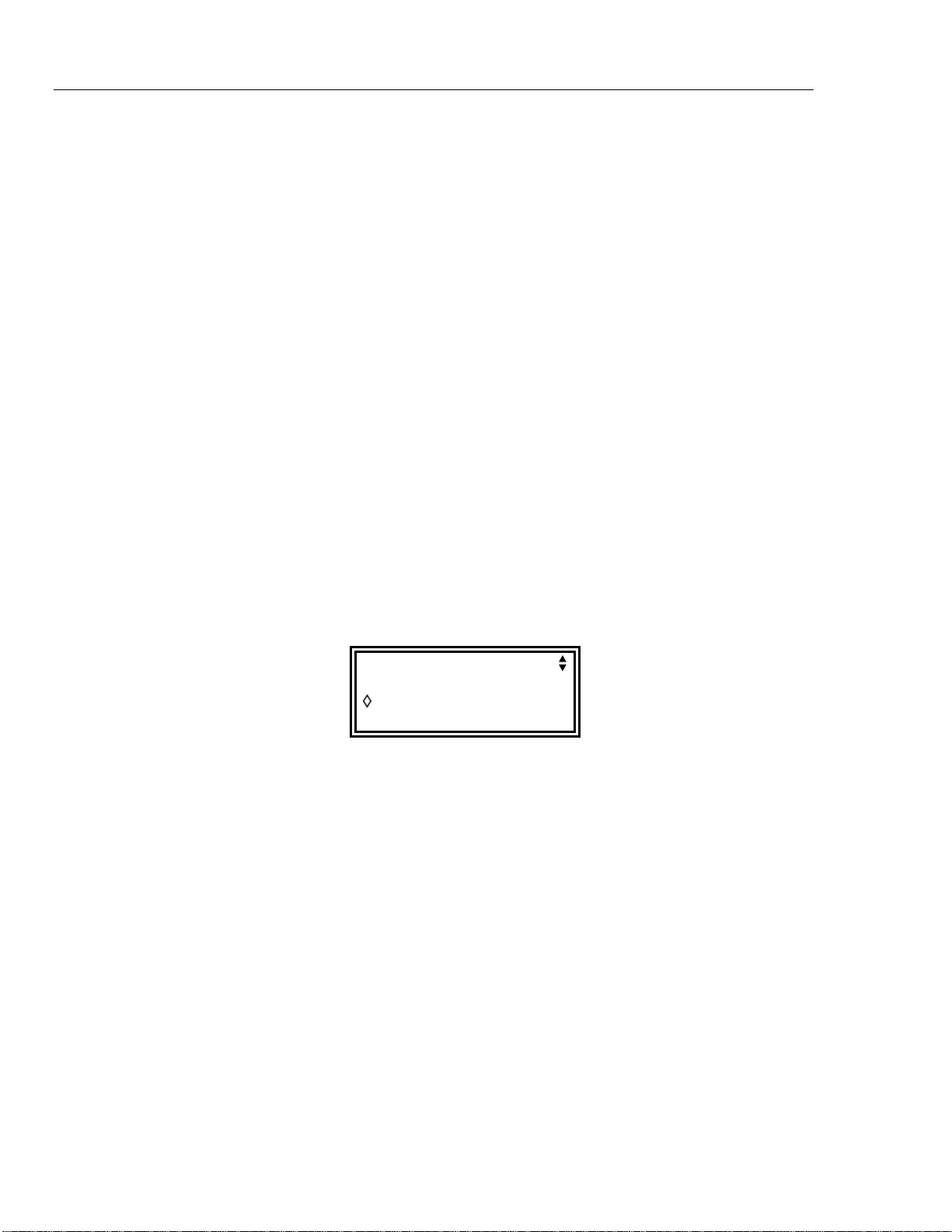
291, 292, 294
Users Manual
Introduction
Both internal and external Sum can be selected; summing can be used to add ‘noise’ to a
waveform, for example, or to add two signals for DTMF (Dual Tone Multiple Frequency)
testing.
External sum can be applied to any or all channels. Internal sum uses the previous
channel as the source, so that for example channel 2 can be added into channel 3; internal
sum is not available on channel 1 or on a single channel instrument.
Summing shares some of the generator’s inter-channel resources with the modulation
modes; as a result neither internal nor external sum can be used with internal modulation
but external modulation is still possible with sum.
To better understand the constraints, the following sections (and chapter 11, Modulation)
should be read with reference to the block diagrams at the end of the manual. These show
the control signals in a single channel and the inter-channel connections.
The diagrams also show the inter-channel trigger connections described in chapter 7,
Triggered Burst and Gate; in general, inter-channel triggering is possible simultaneously
with summing.
External Sum
In sum mode an external signal applied to the SUM input is summed with the
waveform(s) on the specified channel(s). The same sum input signal can be used at
different amplitudes with each of the channels with which it is summed.
Pressing the SUM key calls the SUM set-up screen:
Pressing the source soft-key steps the sum source between off, external and
CHx (where x is the number of the previous channel). With ext selected the screen
is as shown above.
Clipping will occur if the sum input level attempts to drive the channel amplitude above
the maximum 20 V p-p open-circuit voltage. However, the relationship between the
EXT SUM input and the maximum summed output depends not only on the sum input
level but also on the channel's own amplitude setting. This is because the sum input is
applied to the amplifier chain prior to the output attenuators. The amplifier itself is
controlled over a limited range (approximately10 dB) and the full amplitude range of the
channel is achieved by switching in up to five 10 dB attenuation stages. The summed
output cannot exceed the maximum of the range within which the channel output has
been set by choice of amplitude setting. Whereas with internal sum the generator gives
warnings when the combination of sum input and amplitude would cause waveform
clipping (see Internal Sum below), it is the responsibility of the user to observe the
waveforms when using external sum and to make adjustments if the waveform is clipped.
Note that it is not possible to give a simple guide as to where the range breakpoints are
because the use of dc offset, for example, changes these points.
SUM source: ext
CH1 +2.00 Vpp
Within each range an EXT SUM signal of approximately 2 V p-p will force the channel
output from the range minimum to the range maximum; if the channel amplitude is set to
12-2
Find Quality Products Online at: [email protected]
www.GlobalTestSupply.com
Page 90
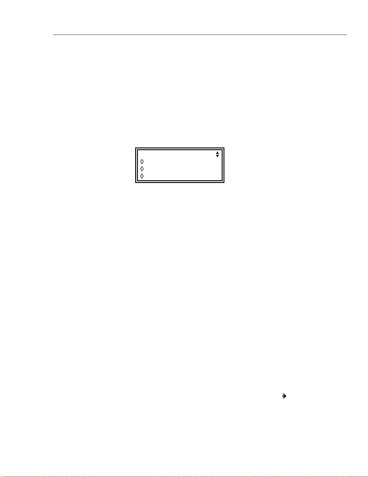
Sum
mid-range then the SUM signal needed to force the output to range maximum is halved
to approximately 1 V p-p.
To facilitate the setting of appropriate sum and amplitude levels the output amplitude of
the selected channel can also be changed from the SUM set-up screen. Press the CHx
soft-key and adjust the amplitude with direct keyboard entries or by using the rotary
control.
External sum cannot be used with internal modulation.
Internal Sum12
Internal Sum
Pressing the SUM key calls the SUM set-up screen:
SUM source: CH1
ratio: 1.00000
CH2 +2.00 Vpp
CH1 +1.00 Vpp
Pressing the source soft-key steps the sum source between off, external and
CHx (where x is the number of the previous channel). CHx is the source of the
internal sum signal.
With CHx selected for internal sum the screen is as shown above. The amplitude of
both the summing channel, CHx
the display, together with the ratio in which they are added. All three parameters can
be selected with the appropriate soft-key and set directly from the keyboard or by the
rotary control. Changing any one parameter will also adjust one of the other two; for
example adjusting the amplitude of either channel will cause the displayed ratio to
change.
The value shown in the ratio field is the CHx amplitude divided by the CHx
amplitude. Adjusting the ratio value directly changes the amplitude of the sum input
signal, CHx, not the channel’s output amplitude. When a value is entered into the
ratio field it is initially accepted as entered but may then change slightly to reflect the
actual ratio achieved with the nearest sum input amplitude that could be set for the given
channel output amplitude.
Warnings are given when either a ratio, sum input or output amplitude change is
attempted which would cause the channel's output to be driven into clipping.
In general it is recommended that the amplitude of the sum input is not greater than the
channel amplitude, i.e. the ratio is less than or equal to 1; most ratio values can be set,
down to very small signal levels. If the sum input is greater than the channel amplitude
there will be combinations when the ratio can be set to a little greater than 1. Note that
the software will always accept an entry, make the calculation and, if the combination is
not possible, return the instrument to its last legitimate setting.
+1, and the internal sum signal, CHx, are shown in
+1
The amplitude of the channel being used for the internal sum signal can still be adjusted
on its own AMPLITUDE set-up screen; its status screen shows the message
indicate that it is being used as a source for channel x.
Internal sum cannot be used with internal modulation.
12-3
Find Quality Products Online at: [email protected]
www.GlobalTestSupply.com
x to
Page 91

Chapter 13
Synchronizing
Title Page
Introduction........................................................................................................ 13-2
Inter-Channel Synchronization.......................................................................... 13-2
Synchronizing Principles............................................................................... 13-2
Master-Slave Allocation................................................................................ 13-2
Phase-Setting Between Channels .................................................................. 13-4
Other Synchronizing Considerations............................................................. 13-4
Synchronizing two generators............................................................................ 13-5
Connections for Synchronization .................................................................. 13-6
Generator Set-Ups......................................................................................... 13-6
Synchronizing................................................................................................ 13-7
13-1
Find Quality Products Online at: [email protected]
www.GlobalTestSupply.com
Page 92
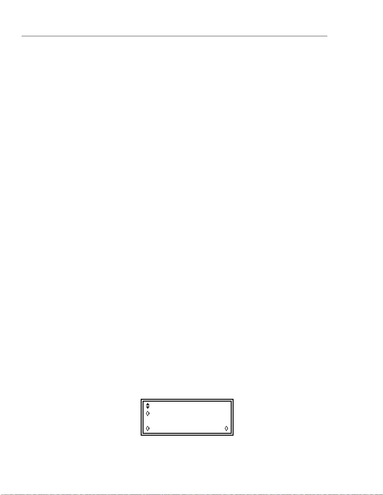
291, 292, 294
Users Manual
Introduction
Inter-Channel Synchronization
Synchronizing Principles
Two or more channels in one multi-channel generator can be synchronized together and
precise phase differences can be set between the channels. Two separate generators can
also be synchronized, giving a maximum of 8 channels that can be operated
synchronously.
This section covers the use of a multi-channel instrument to produce two or more
synchronous signals, and certain restrictions which apply to some specific waveform and
frequency combinations.
Frequency synchronizing is achieved by using the clock output from a master channel to
drive the clock inputs of one or more slave channels. Any one channel can be the master
and any or all the others can be slaves; master, slaves and independent channels can be
mixed on the same instrument.
When frequency synchronization is switched on, an internal synchronizing signal from
the CPU synchronizes the channels at the specified inter-channel phase and resynchronizes them automatically every time the frequency is changed. The clock and
internal synchronization signals are shown in the inter-channel block diagram in the
appendix. Channels to be synchronized together must all be operated in continuous
mode.
For DDS-generated waveforms (see Principles of Operation in chapter 4) it is the
100 MHz signal that is distributed from master to slaves and channels can, in principle,
be frequency-synchronized with any frequency combination. However, the number of
cycles between the phase-referenced points will be excessively large unless the ratio is a
small rational number; for example a 2 kHz signal could be synchronized usefully with
10 kHz, 50 kHz, 100 kHz, etc., but not with 2.001 kHz.
For clock synthesized waveforms it is the PLL clock of the master which is distributed
from master to slaves; the clock frequency for master and slaves is therefore always the
same. The number of points comprising the waveforms should also be the same to ensure
that the waveforms themselves appear locked.
From the foregoing it is clear that only DDS slaves can be synchronized to a DDS master
and only clock synthesized slaves can be synchronized to a clock synthesized master. In
practice the constraints described are not severe as the most common use of
synchronization is to provide outputs of the same waveform at the same frequency, or a
harmonic of it, often with controlled phase offsets.
Master-Slave Allocation
Press the front panel INTER CHannel key to call up the inter-channel set-up screen.
mode: indep
phase: +000.0º
(actual: +000.0º
status: off view
13-2
Find Quality Products Online at: [email protected]
www.GlobalTestSupply.com
Page 93
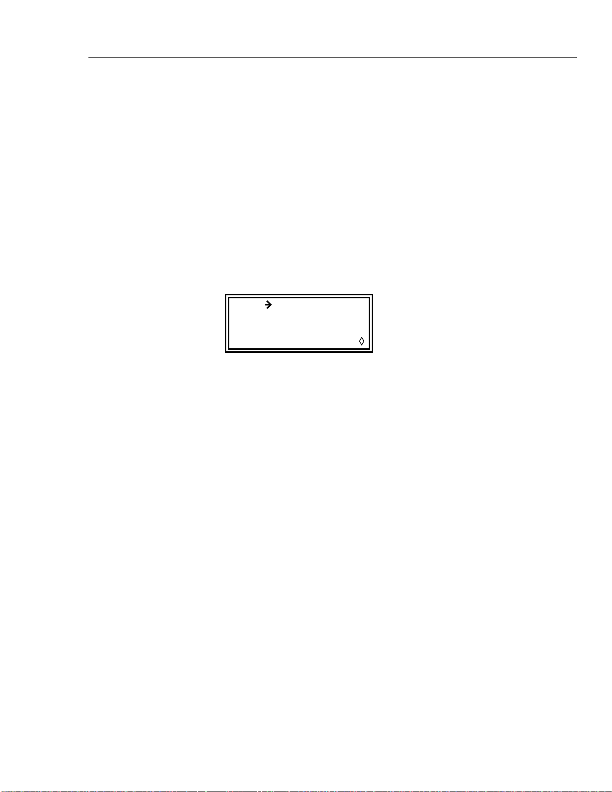
Synchronizing
The mode soft-key can be used to select between independent, master,
master/freq and slave; the default mode is independent. Only one
master can be set; more than one master can be selected but when synchronization is
turned on with the status soft-key the set-up will be rejected. Master/freq
selects the master and sets frequency-tracking; for this to be operational the master and
slave(s) must be set to the same frequency when synchronization is turned on. In this
mode, when the frequency of the master is changed the frequency of the slaves also
changes and the slaves are re-synchronized to the master.
Master/freq is the default mode when the waveforms are clock synthesized (arb,
pulse, etc); if master has been set instead the mode will automatically change to
master/freq when synchronization is turned on. The frequency of clock synthesized
waveform slaves always therefore tracks the master. Finally, slave selects those
channel(s) which are to be synchronized to the master.
At any time, pressing the view soft-key gives a graphical view of the master-slave setup, for example:
Inter-Channel Synchronization13
CH
indep - - - Y
master Y - - -
slave - Y Y - exit
Channel synchronization is turned on or off with the status soft-key. Any illegal
setting combinations will result in an error message when an attempt is made to turn
status on. Any of the following conditions will cause an error (see also the Synchronizing
Principles section for a discussion of the set-up constraints):
1. More than one master channel is enabled.
2. No master channel is enabled.
3. The synchronized channels contain a mixture of DDS and PLL generated waveforms.
4. Frequency tracking is enabled (mode: master/freq) but the frequencies are not the
same on all channels. If clock synthesized waveforms are synchronized the mode
will be forced to frequency tracking.
5. A synchronized channel is not set to continuous mode.
6. An attempt is made to turn on synchronization with a frequency set too high.
7. An attempt is made to set the frequency too high with synchronization on. This error
does not set synchronization to off, the system simply inhibits the setting of the
incorrect frequency.
1 2 3 4
In addition to the illegal setting combinations there are further considerations which
affect the phase resolution and accuracy between channels; see below.
13-3
Find Quality Products Online at: [email protected]
www.GlobalTestSupply.com
Page 94
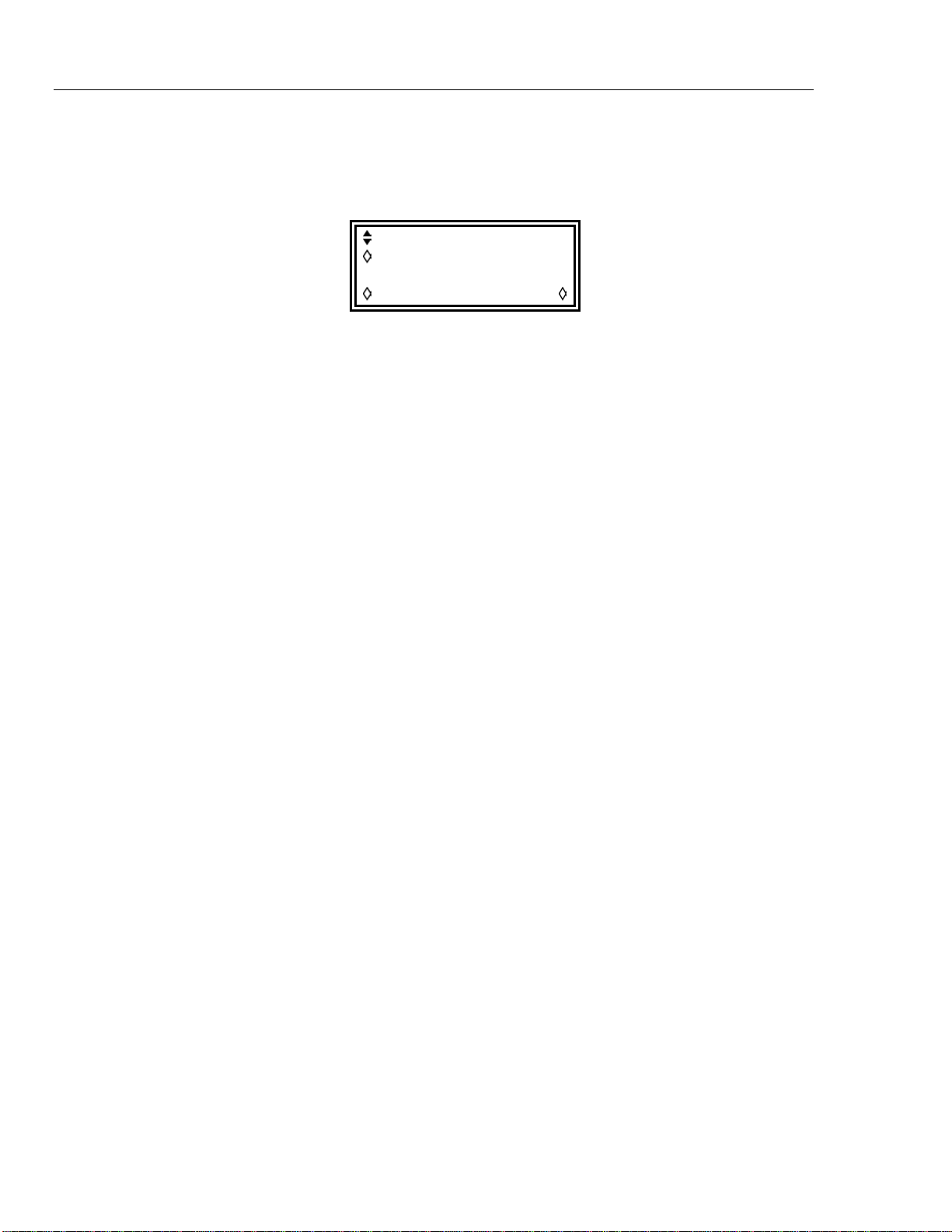
291, 292, 294
Users Manual
Phase-Setting Between Channels
The inter-channel set-up screen also has a field for setting up the phase of the slaves with
respect to the master:
mode: indep
phase: +000.0º
(actual: +000.0º
status: off view
Selecting the phase soft-key allows the phase to be set by direct keyboard entry or by
rotary control. Setting the phase of a slave positive advances the waveform of the slave
with respect to the master; setting it negative delays the slave with respect to the master.
The phase of each slave channel can be set independently. The phase of the master can
also be set, although this is intended primarily for use in phase-synchronization between
two generators. If both the master and the slaves are set to +90 °, say, on the same
generator then the waveforms will all be in phase again; if the master is set to +90 ° and
the slaves set to -90 ° the master and slave waveforms will be 180 ° out of phase.
DDS-generated waveforms can be synchronized with 0.1 ° resolution up to their
maximum available frequency.
The phase-locking resolution of arbitrary waveforms will be less than 0.1 ° for
waveforms of less than 3600 points. The phase is fixed at 0 ° for pulses, pulse-trains and
sequences.
Below is a summary of the phase control and frequency range for different waveforms.
Waveform Max waveform
frequency
Sine, cosine,
haversine, havercosine
40 MHz
Phase control
range, resolution
± 360 °, 0.1°
Square 50 MHz ± 360 °, 180 °
Triangle 500 kHz ± 360 °, 0.1°
Ramp 500 kHz ± 360 °, 0.1°
Sin(x)/x 500 kHz ± 360 °, 0.1°
Pulse & Pulse Train 40 MHz ± 360 °, 360 ° ÷ length or 0.1 °
Arbitrary 100 MS/s clock ± 360 °, 360 ° ÷ length or 0.1 °
Sequence 100 MS/s clock 0 ° only
Other Synchronizing Considerations
The Master-Slave Allocation and Phase-Setting sections contain tables of specific
limitations on the selection of frequency, waveform type and phase-setting range and
resolution. The following further points should also be considered.
• The waveform filters introduce a frequency-dependent delay above about 1 MHz;
this will affect the accuracy of the phase between synchronized waveforms at
different frequencies, e.g. 500 kHz and 5 MHz.
• Square waves, which are 2-point clock synthesized waveforms will not reliably
synchronize to other clock synthesized waveforms.
13-4
Find Quality Products Online at: [email protected]
www.GlobalTestSupply.com
Page 95

Synchronizing
• Pulse and pulse train waveforms will synchronize to other pulse and pulse-train
waveforms (and with each other) but should be built with equal periods.
Synchronizing two generators13
• Arb waveforms should be
create an error message).
When synchronization is turned on with the status soft-key
automatically after every phase or frequency setting change. This re-synchronization
may, depending on the type of waveforms used, cause an interruption of the waveforms
as the phases are established. The following show the different possibilities when a
frequency is changed.
DDS waveforms with master mode set
There will always be an interruption but this is the only conditi
frequencies of the waveform to be different.
DDS waveforms with master/freq mode set.
The frequencies of the waveforms will be the same an
Clock synthesized waveforms
Master/freq mode will be set automatically and there will always be an interruption when
the frequency is changed.
Clock synthesized waveforms with exte
This is the recommended method for synchronizing a
have external arb clock selected before they are synchronized. The ext arb clock may be
provided by an external signal at the ARB CLOCK IN/OUT socket or by the system
clock.
the same length (although this is not forced and does not
the slaves are re-synchronized
on which allows the
d there will be no interruption.
rnal arb clock selected
rbs and pulses. The channels must
Synchronizing two generators
Two generators can be synchronized together following the procedure outlined below. It
is possible to link more than two generators in this way but results are not guaranteed.
Frequency synchronization is achieved by using t
generator to drive the clock input of a slave. The additional connection of an initializing
SYNC signal permits the slave to be synchronized such that the phase relationshi
between master and slave outputs is that specified on the slave generator’s inter-channel
set-up screen.
Synchronization is only possible between generators when the ratio of the m
slave frequencies is rational, e.g. 3 kHz can be synchronized with 2 kHz but not with
7 kHz. Special considerations arise with waveforms generated by clock synthesis mode
(square wave, arbitrary, pulse, pulse train and sequence) because of the relatively poor
precision with which the frequency is actually derived in the hardware. With these
waveforms, frequencies with an apparently rational relationship, say, for example 3:1,
may be individually synthesized such that the ratio is not close enough to 3:1 to maintain
synchronization over a period of time; the only ratios guaranteed to be realized precisely
are integer powers of 2 because the division stages in clock synthesis mode are binary.
A further complication arises with arb waveforms because waveform frequency depends
on b
oth waveform size and clock frequency (waveform frequency = clock frequency
divided by waveform size). The important relationship with arbs is the ratio of clock
frequencies and the above considerations on precision apply to them. The most practical
use of synchronization will be to provide outputs at the same frequency, or maybe
harmonics, but with phase differences.
he clock output from the master
p
aster and
13-5
Find Quality Products Online at: [email protected]
www.GlobalTestSupply.com
Page 96
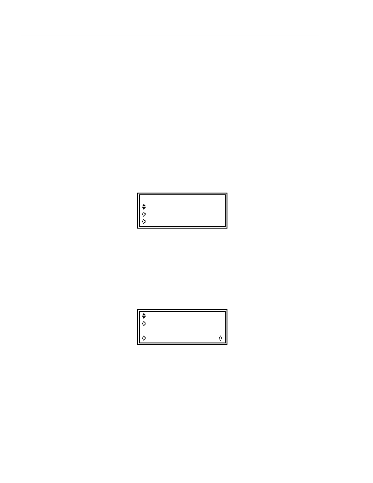
291, 292, 294
Users Manual
Connections for Synchronization
Generator Set-Ups
The clock connection arrangement is for the rear panel REF CLOCK IN/OUT of the
master (which will be set to master) to be connected directly to the
REF CLOCK IN/OUT socket of the slave (which will be set to slave).
Similarly the synchronizing connection is from any SYNC OUT of the master, which all
default to phase lock, to the TRIG IN input of the slave.
Each generator can have its main parameters set to any value, with the exception that the
ratio of frequencies between master and slave must be rational and each generator can be
set to any waveform, subject to the limitations described above. Best results will be
achieved if the constraints forced on inter-channel synchronization, described in the
previous chapter, are adopted for inter-generator synchronization.
The master has its REF CLOCK IN/OUT set to master on the REF/SYS CLOCK
menu called by the sys/ref soft-key on the UTILITY screen. (Refer to chapter 15,
System Operations from the Utility Menu.)
REF/SYS CLOCK:
sys clk: off
freq: 10.000000kHz
ref clk master
Repeated presses of the ref clk soft-key toggle between the possibilities
The slave is set to slave. Setting the master generator to master forces the mode
to continuous and defaults the SYNC OUT output to phase lock. Only one of the
SYNC OUTs is needed for inter-generator synchronization; the others may be reset to
other functions if required. The phase relationship between the slave and the master is set
on the inter-channel set-up screen of the slave, accessed by pressing the INTER CHannel
key.
mode: indep
phase: +000.0º
(actual: +000.0º
status: off view
The phase of the slave generator is set by adjusting the phase of the master channel on
the slave generator’s inter-channel set-up screen exactly as described under Phase-Setting
Between Channels above. The phase(s) of slave channel(s) on the slave generator are set
up with respect to the master in the way described in that same section.
When a single-channel generator (which has no inter-channel set-up key or screen) is the
slave, its phase is set using the TRIGGER/GATE SETUP screen. The Trigger Phase
section of chapter 7, Triggered Burst and Gate covers this process.
The convention adopted for the phase relationship between generators is that a positive
phase setting advances the slave generator with respect to the master and a negative
setting delays the slave generator. The status of the slave generator on the inter-channel
set-up screen must be set to on (this is automatic on the single channel instrument).
13-6
Find Quality Products Online at: [email protected]
www.GlobalTestSupply.com
Page 97

Synchronizing
Hardware delays become increasingly significant as frequency increases, causing
additional phase delay between the master and slave. However, these delays can be
largely nulled out by ‘backing off’ the phase settings of the slave.
Typically these hardware delays are as follows:
DDS waveforms: <± 25 ns <1 ° to 100 kHz
Clock synthesized waveforms: <300 ns <1 ° to 10 kHz.
Clearly a multi-channel generator gives much closer inter-channel synchronization and is
the reco
Synchronizing
Having made the connections and set up the generators as describ
paragraphs, synchronization is achieved by pressing the MAN TRIG key of the slave.
Once sy
MAN T
It is also possible to use an external arb clock when synchronizing two generators. The
generators ar
clock. The same external clock should be applied to both generators.
mmended method for up to 4 channels.
nchronized any change to the set-up will require resynchronization with the
RIG key again.
e set up as described for internal clock but all channels are set to external
Synchronizing two generators13
ed in the preceding
13-7
Find Quality Products Online at: [email protected]
www.GlobalTestSupply.com
Page 98

Chapter 14
Memory Card
Title Page
Introduction........................................................................................................ 14-2
Card Sizes and Formats ..................................................................................... 14-2
Formatting.......................................................................................................... 14-3
Saving Files to a Memory Card......................................................................... 14-3
Avoiding Long Filenames............................................................................. 14-3
Storing and Recalling Set-Ups........................................................................... 14-3
Sorting Files....................................................................................................... 14-5
14-1
Find Quality Products Online at: [email protected]
www.GlobalTestSupply.com
Page 99
291, 292, 294
Users Manual
Introduction
Pressing the UTILITY key calls a list of menus which give access to various system
operations including storing/recalling set-ups from a memory card, error messages, power
on settings and calibration.
The instrument uses compact flash memory cards, i.e. cards that comply with the
Compact Flash Association standard. A compatible memory card and a USB card
reader/writer are supplied with the instrument. The card reader/writer may be connected
to a PC to allow waveform files created on the PC to be written directly to a memory
card. The memory card may then be transferred to the instrument and the waveform
played back immediately. Similarly waveforms created or modified on the instrument
may be transferred to the PC.
To install the card reader/writer follow the instructions supplied with it. For Windows
ME, 2000, XP and later simply plug the device in to a spare USB port and Windows
should detect it; for Windows 98 and 98SE the manufacturer's supplied driver must be
installed from the CD-ROM.
Plug the memory card into the memory card slot. On single-channel instruments this is
on the rear panel; 2- and 4-channel versions have the card slot on the front panel. Ensure
that the pointer on the card aligns with the pointer on the card slot. Push the card gently
until it is fully engaged in the connector. The card may be inserted with the power on or
off.
When a card is inserted in a powered instrument the message
Opening memory card
will appear on the bottom line of the screen, the MEMORY CARD ACTIVE lamp will
light and a short beep will sound. The card is then ready for use as described later in this
chapter.
To remove the memory card, ensure that the MEMORY CARD ACTIVE lamp is off and
pull the card straight out of the card slot.
To avoid the risk of malfunction, card data corruption or
firmware lock-up, never remove the memory card when the
MEMORY CARD ACTIVE lamp is lit.
Card Sizes and Formats
The instrument is compatible with cards ranging in capacity from 32 MB to 1 GB. From
new these cards are formatted with the FAT16 file system. Cards with lower capacity will
be formatted with the FAT12 file system which is not readable by the instrument.
However, it is possible to reformat these smaller cards with the FAT16 file system in the
instrument, from the MEMORY CARD screen, accessed by pressing the
memory card… soft-key on the UTILITY MENU.
Take care when formatting memory cards in a PC as cards with capacities less than
32 MB will by default be formatted as FAT12. Furthermore, Windows XP formats larger
capacity cards FAT32 which is not readable by the instrument. It is also usual to lose a
small amount of capacity when formatting using a PC; this is because the PC treats the
card as a removable hard disk and leaves the first ‘cylinder’ blank. Any card formatted
FAT16 by the instrument should work in a PC.
Caution
When a new or newly formatted card is inserted in the instrument for the first time it will
be prepared for use by adding two directories to the root. These are \WAVES.ARB,
14-2
Find Quality Products Online at: [email protected]
www.GlobalTestSupply.com
Page 100
Memory Card
where waveforms are stored, and \SETUP.ARB, where instrument set-ups are stored.
The instrument will use these directories exclusively for its files. Each directory may
hold up to 510 files, disk capacity permitting. If more than 510 files are stored in these
directories some will be invisible to the instrument because its directory cache buffers are
a finite size.
Formatting14
Formatting
Pressing the memory card… soft-key calls the MEMORY CARD screen:
MEMORY CARD 61·0MB
label: TESTARB3
free: 59·6MB
format… sort dir…
The screen displays the memory card size, its name and the unused capacity. If either the
WAVES or SETUP directories are full the screen will show free: 0·0MB.
The instrument requires cards formatted with the FAT16 file system (see above). This is
the standard format for new card with capacities from 32 MB to 1 GB but previously
used cards may have been reformatted elsewhere.
To reformat as FAT16 press the format… soft-key followed by ok on the
subsequent screen. The instrument will warn that re-formatting will cause any data on the
card to be lost.
Saving Files to a Memory Card
When creating files the instrument uses the 8.3 file naming format where the 8 is the 8
character filename and 3 is the file extension. The user chooses the filename and the
instrument adds the extension. The instrument does not create Windows long filenames.
If long filenames exist on the memory card they are ignored by the instrument and the 8.3
alias name is used instead and will appear on the LCD screen.
Avoiding Long Filenames
If long filenames are allowed to get into the directories that the instrument uses they
consume directory space and will reduce the maximum number of files that can be seen
by the instrument. Unfortunately it is very easy to inadvertently create long filename
entries when using the card reader/writer; simply saving a waveform as wave.wfm will
create a long filename entry and an alias. This is because Windows takes the filename
literally as it is entered and, as 8.3 filenames do not allow lower case, any lower case
letter in a filename will produce a long filename. To avoid the problem in the above
example it is necessary to save the file as WAVE.WFM.
The Waveform Manager application supplied will ensure that all filenames are short
provided that the download to memory card function is used to transfer waveforms to the
card reader/writer.
Storing and Recalling Set-Ups
Complete set-ups can be stored to or recalled from the memory card using the screens
called by the STORE and RECALL keys. On the single-channel instrument the store
function is only available by means of the store… soft key on the UTILITY menu.
14-3
Find Quality Products Online at: [email protected]
www.GlobalTestSupply.com
 Loading...