

Page 1

1523, 1524
Reference Thermometer
Technical Guide
Revision 991701
Page 2

Limited Warranty & Limitation of Liability
Each product from Fluke Corporation, Hart Scientic Division (“Hart”) is warranted to be free
from defects in material and workmanship under normal use and service. The warranty period
is one year(s) for the Reference Thermometer. The warranty period begins on the date of the
shipment. Parts, product repairs, and services are warranted for 90 days. The warranty extends
only to the original buyer or end-user customer of a Hart authorized reseller, and does not apply
to fuses, disposable batteries or to any other product, which in Hart’s opinion, has been misused,
altered, neglected, or damaged by accident or abnormal conditions of operation or handling.
Hart warrants that software will operate substantially in accordance with its functional specications for 90 days and that it has been properly recorded on non-defective media. Hart does not
warrant that software will be error free or operate without interruption. Hart does not warrant
calibrations on the Reference Thermometer.
Hart authorized resellers shall extend this warranty on new and unused products to end-user
customers only but have no authority to extend a greater or different warranty on behalf of Hart.
Warranty support is available if product is purchased through a Hart authorized sales outlet or
Buyer has paid the applicable international price. Hart reserves the right to invoice Buyer for
importation costs of repairs/replacement parts when product purchased in one country is submitted for repair in another country.
Hart’s warranty obligation is limited, at Hart’s option, to refund of the purchase price, free of
charge repair, or replacement of a defective product which is returned to a Hart authorized service center within the warranty period.
To obtain warranty service, contact your nearest Hart authorized service center or send the product, with a description of the difculty, postage, and insurance prepaid (FOB Destination), to
the nearest Hart authorized service center. Hart assumes no risk for damage in transit. Following
warranty repair, the product will be returned to Buyer, transportation prepaid (FOB Destination). If Hart determines that the failure was caused by misuse, alteration, accident or abnormal
condition or operation or handling, Hart will provide an estimate or repair costs and obtain
authorization before commencing the work. Following repair, the product will be returned to the
Buyer transportation prepaid and the Buyer will be billed for the repair and return transportation
charges (FOB Shipping Point).
THIS WARRANTY IS BUYER’S SOLE AND EXCLUSIVE REMEDY AND IS IN LIEU OF
ALL OTHER WARRANTIES, EXPRESS OR IMPLIED, INCLUDING BUT NOT LIMITED
TO ANY IMPLIED WARRANTY OF MERCHANTABILITY OR FITNESS FOR A PARTICULAR PURPOSE. HART SHALL NOT BE LIABLE FOR ANY SPECIAL, INDIRECT, INCIDENTAL. OR CONSEQUENTIAL DAMAGES OR LOSSES, INCLUDING LOSS OF DATA,
WHETHER ARISING FROM BREACH OF WARRANTY OR BASED ON CONTRACT,
TORT, RELIANCE OR ANY OTHER THEORY.
Since some countries or states do not allow limitation of the term of an implied warranty, or
exclusion or limitation of incidental or consequential damages, the limitations and exclusions of
this warranty may not apply to every buyer. If any provision of this Warranty is held invalid or
unenforceable by a court of competent jurisdiction, such holding will not affect the validity or
enforceability of any other provision.
Fluke Corporation, Hart Scientific Division
799 E. Utah Valley Drive • American Fork, UT 84003-9775 • USA
Phone: +1.801.763.1600 • Telefax: +1.801.763.1010
E-mail: support@hartscientic.com
www.hartscientific.com
Specications subject to change without notice. • Copyright © 2008 • Printed in USA
Page 3

Table of Contents
1 Before You Start .......................................................................1
1.1 Introduction ............................................................................................... 1
1.2 Standard Equipment ................................................................................. 1
1.3 Safety Information ..................................................................................... 1
1.3.1 Warning .....................................................................................................1
1.3.2 Cautions .......................................................................................................... 2
1.4 CE Comments ........................................................................................... 3
1.4.1 EMC Directive .................................................................................................3
1.4.2 Immunity Testing .............................................................................................3
1.4.2.1 For Use As a Portable (Hand-held) Instrument ...................................................... 3
1.4.2.2 For Use As a Benchtop Instrument (AC Adapter) .................................................. 4
1.4.3 Locking out non SI units ..................................................................................4
1.5 Using Clamp-On Ferrites .......................................................................... 4
1.6 Emissions Testing ..................................................................................... 5
1.7 Low Voltage Directive (Safety) .................................................................. 5
1.8 Authorized Service Centers ...................................................................... 5
2 Quick Start ................................................................................7
2.1 Setup ......................................................................................................... 7
2.2 Specifications ........................................................................................ 17
3 General Operation .................................................................23
3.1 Battery..................................................................................................... 23
3.2 DC Power Source ................................................................................... 23
3.3 Probe ...................................................................................................... 24
3.3.1 Internal or External reference junction compensation may be used with this
instrument. ................................................................................................................ 25
3.3.2 TC Internal Reference Junction ..................................................................... 25
3.3.3 TC External Reference Junction .................................................................... 25
3.4 Probe Lock Function ............................................................................... 25
3.5 INFO-CON Connector ............................................................................. 26
4 Display Functions and User Interface ..................................29
4.1 Main Screen ............................................................................................ 29
4.2 STATS ...................................................................................................... 29
4.3 °C °F ....................................................................................................... 29
iii
Page 4

1523, 1524 Reference Thermometer
4.4 HOLD ...................................................................................................... 29
4.5 SETUP ..................................................................................................... 30
4.5.1 Channel T1 ....................................................................................................30
4.5.1.1 Probe .................................................................................................................... 30
4.5.1.2 Config ................................................................................................................... 30
4.5.1.3 Base X .................................................................................................................. 30
4.5.1.4 Aux Displ .............................................................................................................. 30
4.5.1.5 Temp Res .............................................................................................................. 31
4.5.1.6 RJ ......................................................................................................................... 31
4.5.2 Channel T2 (1524 Only) ................................................................................ 31
4.5.2.1 Probe .................................................................................................................... 32
4.5.2.2 Config ................................................................................................................... 32
4.5.2.3 Base X .................................................................................................................. 32
4.5.2.4 Aux Displ .............................................................................................................. 32
4.5.2.5 Temp Res .............................................................................................................. 33
4.5.3 Instrument .....................................................................................................33
4.5.3.1 Fast Scan Mode ................................................................................................... 33
4.5.3.2 Contrast ................................................................................................................ 33
4.5.3.3 Auto-Off ................................................................................................................ 33
4.5.3.4 Backlight Time ...................................................................................................... 33
4.5.3.5 Serial Port ............................................................................................................. 33
4.5.3.6 Baud Rate ............................................................................................................. 34
4.5.3.7 Date/Time ............................................................................................................. 34
4.6 SAVE ....................................................................................................... 34
4.7 ARROWS, UP, DOWN ............................................................................. 34
4.8 ENTER ..................................................................................................... 35
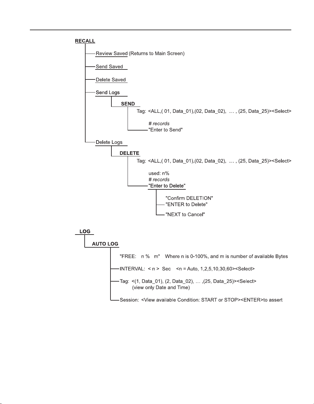
4.9 RECALL .................................................................................................. 35
4.9.1 Review Saved ................................................................................................ 35
4.9.2 Send Saved ...................................................................................................35
4.9.3 Delete Saved .................................................................................................35
4.9.4 Send Logs .....................................................................................................35
4.9.5 Delete Logs ...................................................................................................36
4.10 NEXT ....................................................................................................... 36
4.11 SHIFT ...................................................................................................... 36
4.12 RESET ..................................................................................................... 36
4.13 Ω mV ....................................................................................................... 36
4.14 TREND .................................................................................................... 36
4.15 LOG ........................................................................................................ 37
4.15.1 Free ...............................................................................................................37
4.15.2 Interval ...........................................................................................................37
4.15.3 Tag ................................................................................................................. 38
iv
Page 5

4.15.4 Session ..........................................................................................................38
4.16 HOME ..................................................................................................... 38
5 LOGS .......................................................................................39
5.1 DEMAND LOG ........................................................................................ 39
5.2 AUTO-LOG ............................................................................................. 39
5.2.1 Auto-Log Operation ....................................................................................... 39
5.2.2 Sending Auto Log Data to a Computer .........................................................41
5.2.3 Data Upload Format ......................................................................................41
5.2.4 Deleting Auto Log Data .................................................................................41
6 Digital Communication Interface ..........................................43
6.1 Wiring ...................................................................................................... 43
6.1.1 Setup .............................................................................................................44
6.1.2 Serial Operation ............................................................................................44
6.1.3 Data Upload Format .....................................................................................44
6.2 Command Syntax ................................................................................... 44
6.3 Serial Commands by Function or Group ................................................ 45
6.4 Serial Commands - Alphabetic Listing ................................................... 48
7 Calibration of Your Reference Thermometer Readout ........77
7.1 General ................................................................................................... 77
7.2 Introduction ............................................................................................. 77
7.3 Terminology............................................................................................. 77
7.4 Fundamentals ......................................................................................... 77
7.5 Environmental Test Conditions ................................................................ 77
7.6 Calibration Equipment ............................................................................ 77
7.7 Manual Calibration .................................................................................. 78
7.7.1 General .......................................................................................................... 78
7.7.2 As Found Data Procedure ............................................................................. 80
7.7.2.1 As Found Calibration Parameters ........................................................................ 80
7.7.2.2 As Found Data ...................................................................................................... 80
7.7.3 Alignment Procedure.....................................................................................80
7.7.3.1 Alignment Test Data ............................................................................................. 80
7.7.3.2 Calculate New Adjustment Values ....................................................................... 80
7.7.4 As Left Data ................................................................................................... 80
7.8 Preparation for Reference Thermometer Calibration .............................. 80
7.8.1 Serial Communication ................................................................................... 80
7.8.2 Cabling .........................................................................................................81
v
Page 6

1523, 1524 Reference Thermometer
7.8.3 Scan Mode ....................................................................................................81
7.8.4 AC Adapter ...................................................................................................81
7.9 Manual Calibration Process .................................................................... 81
7.9.1 Procedure ...................................................................................................... 82
7.9.1.1 Visual Inspection .................................................................................................. 82
7.9.1.2 1523/24 Calibration Parameters (As Found) ........................................................ 82
7.9.1.3 1523/24 Accuracy Test (As Found) ...................................................................... 84
7.9.2 1523/24 Alignment ........................................................................................ 89
7.9.2.1 L75_OHMS Range ................................................................................................ 92
7.9.2.2 LO_OHMS Range ................................................................................................. 92
7.9.2.3 MED_OHMS Range .............................................................................................. 92
7.9.2.4 HI_OHMS Range .................................................................................................. 92
7.9.2.5 Millivolt Range ...................................................................................................... 92
7.9.3 1523/24 As Left Test Data .............................................................................93
8 Troubleshooting .....................................................................95
9 Maintenance ...........................................................................97
Index ...............................................................................................99
vi
Page 7

Figures
Figure 1 Locking out non SI units ...................................................................... 4
Figure 2 Clamp-On Ferrite ................................................................................. 5
Figure 3 Input/Output Connections - 1523 ........................................................ 7
Figure 4 Input/Output Connections - 1524 ........................................................ 8
Figure 5 Keys ..................................................................................................... 9
Figure 6 1523 Menu ......................................................................................... 11
Figure 7 1523 Menu (cont) .............................................................................. 11
Figure 8 1523 Menu (cont) .............................................................................. 12
Figure 9 1524 Menu ......................................................................................... 14
Figure 10 1524 Menu (cont) ............................................................................ 14
Figure 11 1524 Menu (cont) ............................................................................ 15
Figure 12 1524 Menu (cont) ............................................................................ 16
Figure 13 1524 Menu (cont) ............................................................................ 17
Figure 14 1524 Menu (cont) ............................................................................ 17
Figure 15 12V DC Power source Polarity ........................................................ 24
Figure 16 Probe wiring diagrams..................................................................... 27
Figure 17 RS-232 wiring .................................................................................. 44
Figure 18 Flow chart for manual calibration .................................................... 79
vii
Page 8

1523, 1524 Reference Thermometer
Tables
Table 1 International Symbols ............................................................................ 3
Table 2 1523 Input/Output Connections ............................................................ 7
Table 3 1524 Input/Output Connections ............................................................ 8
Table 4 1523 Key Functions ............................................................................. 10
Table 5 1524 Key Functions ............................................................................. 12
Table 6 General Specifications ....................................................................... 18
Table 7 Millivolt Measurement .......................................................................... 18
Table 8 Reference Junction Compensation ..................................................... 18
Table 9 Ohms Measurement, RTDs ................................................................ 18
Table 10 Ohms Measurement, Thermistor ...................................................... 19
Table 11 Equivalent temperature accuracies derived from primary
specifications (Ω, mV) ............................................................................ 19
Table 12 Temperature, Thermocouples External Reference Junction ............. 20
Table 13 Temperature, RTD Ranges
and Accuracies (RTD-90) ................................................................................ 21
Table 14 Temperature, Thermistor ................................................................... 21
Table 15 Fast Scan Mode Specifications ........................................................ 21
Table 16 Sample Interval per Channel in Seconds .......................................... 21
Table 17 Channel to Channel Differential Specifications ................................ 22
Table 18 Commands by Function or Group ..................................................... 46
Table 19 Statistical Types ................................................................................ 73
Table 20 Probe Conversion Types ................................................................... 73
Table 21 Probe Characterization Parameters .................................................. 74
Table 22 Calibration Range Identifiers ............................................................. 75
Table 23 Demand Log Statistical Types .......................................................... 76
Table 24 Error Messages ................................................................................. 76
Table 25 Test Equipment Specifications .......................................................... 78
Table 26 Standard Reference Resistor Specification ...................................... 78
Table 27 Standard Voltage Reference Specification ....................................... 78
Table 28 1523/24 Accuracy Test Settings and Specifications ......................... 81
Table 29 1523/24 Accuracy Test Settings and Specifications – Voltage ......... 82
Table 30 As Found Readout/Calibration Parameter Settings .......................... 82
Table 31 1523/24 Alignment Settings .............................................................. 89
viii
Page 9

Before You Start
Safety Information
1 Before You Start
1.1 Introduction
The Reference Thermometers (1523, 1524) are designed to be reliable, stable, temperature measuring instruments that can be used in the eld or laboratory. They offer
accuracy, portability, and speed for nearly every eld calibration application. The
instruments have been designed with the eld user in mind and are easy to use while
maintaining stability, uniformity, and accuracy comparable to some laboratory instruments. Your Fluke 1523 and 1524 thermometers are a handheld, battery operated
instrument that measures temperature using Platinum resistance Thermometers (PRT),
Thermistors, and Thermocouples (TC).
1.2 Standard Equipment
Unpack the instrument carefully and inspect it for any damage that may have occurred
during shipment. If there is shipping damage, notify the carrier immediately.
Verify that the following components are present:
●
1523/1524 Reference Thermometer with 3 AA batteries
●
AC Adapter, with power cord
●
RS-232 Cable
●
User’s Guide
●
Documentation CD
●
Report of Calibration and calibration label
●
Clamp-on ferrite(s)
If all items are not present, contact an Authorized Service Center. (See Section 1.8,
Authorized Service Centers on page 5.)
1.3 Safety Information
The Reference Thermometer is designed in accordance with EN 61010-1 {2nd Edition}, and CAN/CSA 22.2 No 61010.1-04. Use this instrument only as specied in this
manual, otherwise the protection provided by the instrument may be impaired.
A Warning identies conditions and actions that pose hazard(s) to the user; a Caution
identies conditions and actions that may damage the instrument being used.
International symbols used on the reference thermometer and in this manual are explained in Table 1 on page 3.
1.3.1 Warning
To avoid possible electric shock or personal injury:
●
Do not use the reference thermometer in environments other than those listed in
the user’s guide.
1
Page 10

1523, 1524 Reference Thermometer
Safety Information
●
Do not use the reference thermometer for any application other than that which
is specied. The instrument was designed for temperature measurement and
calibration. Any other use of the instrument may cause unknown hazards to the
user.
●
If the reference thermometer is used in a manner not in accordance with the
equipment design, the operation and the protection provided by the instrument
may be impaired. In addition, safety hazards may arise.
●
Do not apply more than the rated voltage, as marked on the reference
thermometer, between the inputs, or between any input and earth ground (30 V,
24 mA max all terminals).
●
Follow all equipment safety procedures.
●
Calibration equipment should only be used by trained personnel.
●
The reference thermometer is intended for indoor use only.
●
Before you use the instrument, inspect the case. Look for cracks or missing
plastic. Pay particular attention to the insulation surrounding the connectors. Do
not use the reference thermometer if it appears damaged or operates abnormally.
Protection may be impaired. When in doubt, have the instrument serviced.
●
Always use an isolated RTD or PRT (metal sheath isolated from lead wires).
●
Make sure the battery door is closed and latched before you operate the
reference thermometer.
●
Do not operate the reference thermometer around explosive gas, vapor, or dust.
●
For battery operation use only 3 AA batteries, properly installed in the reference
thermometer case.
●
On the 1524 model, thermocouples can only be used on channel 1.
1.3.2 Cautions
To avoid possible damage to the reference thermometer or to equipment under test:
●
Do not apply more than the rated voltage, as marked on the reference
thermometer, between the inputs, or between any input and earth ground (30 V
24 mA max all terminals).
●
Unless recalibrating the instrument DO NOT change the values of the
calibration constants from the factory set values. The correct setting of these
parameters is important to the safety and proper operation of the instrument.
●
The instrument and any thermometer probes used with it are sensitive
instruments that can be easily damaged. Always handle these devices with care.
DO NOT allow them to be dropped, struck, stressed, or overheated.
●
DO NOT operate this instrument in an excessively wet, oily, dusty, or dirty
environment.
●
Use the proper probes, function and range for your measurement.
●
Ensure probe coefcients are downloaded.
2
Page 11
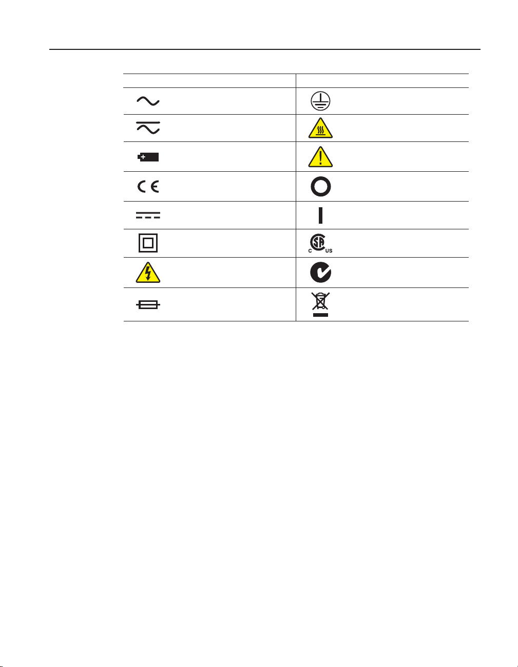
Table 1 International Symbols
Symbol Description Symbol Description
AC (Alternating Current) PE Ground
AC-DC Hot Surface (Burn Hazard)
Before You Start
CE Comments
Battery
Complies with European Union
directives
DC On
Double Insulated Canadian Standards Association
Electric Shock C-TICK Australian EMC mark
Fuse
1.4 CE Comments
1.4.1 EMC Directive
Hart Scientic’s equipment has been tested to meet the European Electromagnetic
Compatibility Directive (EMC Directive, 2004/108/EC ). The Declaration of Conformity for your instrument lists the specic standards to which the unit was tested.
The instrument was designed specically as a test and measuring device. Compliance
to the EMC directive is through EN 61326-1:2006 Electrical equipment for measurement, control and laboratory use – EMC requirements
As noted in the EN 61326-1, the instrument can have varying congurations. The
instrument was tested in a typical conguration with shielded RS-232 cables.
Read the User’s Guide (Important
Information)
Off
The European Waste Electrical
and Electronic Equipment (WEEE)
Directive (2002/96/EC) mark.
1.4.2 Immunity Testing
1.4.2.1 For Use As a Portable (Hand-held) Instrument
The instrument was tested to Basic Immunity Requirements for portable test and measurement equipment.
3
Page 12

1523, 1524 Reference Thermometer
Using Clamp-On Ferrites
1.4.2.2 For Use As a Benchtop Instrument (AC Adapter)
The instrument was tested to Immunity Requirements for Controlled EM Environments. Utilized in this state the instrument is designed to operate in a controlled
electromagnetic environment. The instrument experiences degradation in the presence
of strong elds in the frequency range of 150 to 200 MHz and we suggest that it not be
used in close proximity to VHF transmitters.
1.4.3 Locking out non SI units
Through a specic key-press sequence, the user can choose to disable the °C °F toggle
switch so that temperature is displayed in SI units only. Once the units toggle switch
has been locked, subsequent key presses will not allow temperature to be displayed in
°F.
Instructions for locking out non SI units (see illustration below)
1. Simultaneously press and hold down the °C °F key and the BACKLIGHT key,
press the POWER ON key
2. The display will read: SI units only ON
3. Release the °C °F and the BACKLIGHT key
4. The °C °F key will no longer toggle between units
Press and hold
°C °
+
F
Press
Display reads:
Release
Figure 1
Locking out non SI units
Repeating the steps above will enable the °C °F toggle switch allowing temperature to
be displayed in °F. The display will read: SI units only OFF
SI units only ON
+
F
°C °
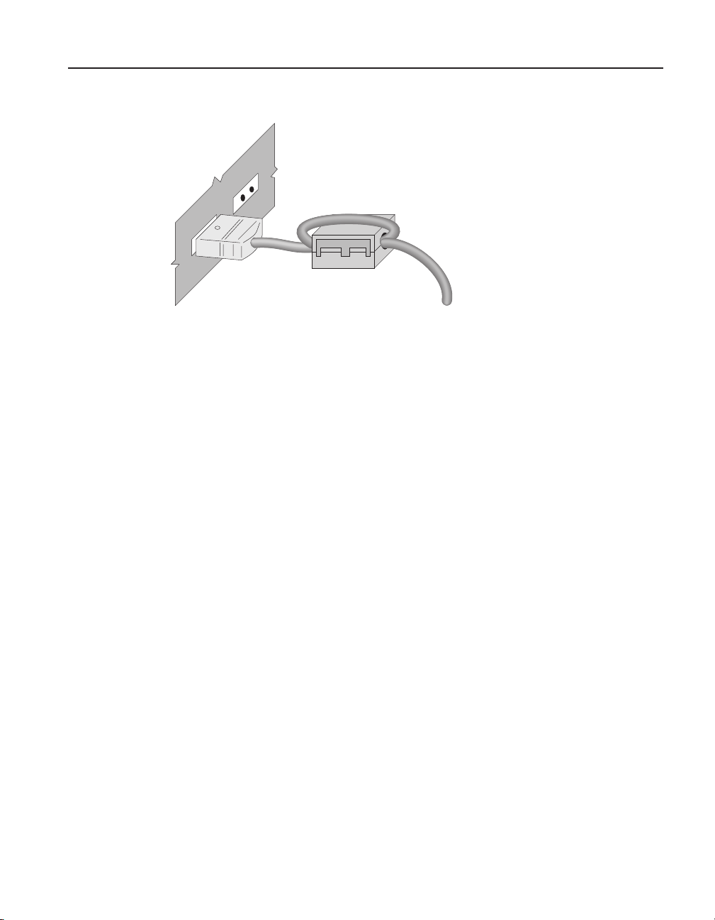
1.5 Using Clamp-On Ferrites
Clamp-on ferrites are provided for use in improving the instrument’s electromagnetic
(EM) immunity in environments of excessive EM interference, like areas of heavy
industrial equipment. We recommend placing the ferrites on the cables of probes attached to the instrument.
To attach a ferrite to a probe cable, make a loop in the cable near the connector and
clamp the ferrite around half of the loop as shown in the diagram. The ferrite can be
4
Page 13
Authorized Service Centers
probe cable
easily detached and moved to a new probe when needed. (See Figure 2 on opposite
page.)
clamp-on ferrite
Figure 2
Clamp-On Ferrite
1.6 Emissions Testing
The instrument fullls the limit requirements for Class B.
1.7 Low Voltage Directive (Safety)
In order to comply with the European Low Voltage Directive (2006/95/EC), Fluke
equipment has been designed to meet the EN 61010-1.
Before You Start
1.8 Authorized Service Centers
Please contact one of the following authorized Service Center to coordinate service on
your Fluke product:
Fluke Corporation
Hart Scientic Division
Phone: +1.801.763.1600
Fluke Nederland B.V.
Phone: +31-402-675300
Fluke Int’l Corporation - CHINA
Phone: +86-10-6-512-3436
Fluke South East Asia Pte Ltd. - SINGAPORE
Phone: +65-6799-5588
When contacting a Service Center for support, please have the following information
available:
●
Model Number
●
Serial Number
●
Complete description of the problem
5
Page 14

Page 15
2 Quick Start
RS
232
12
V DC
30
V MAX
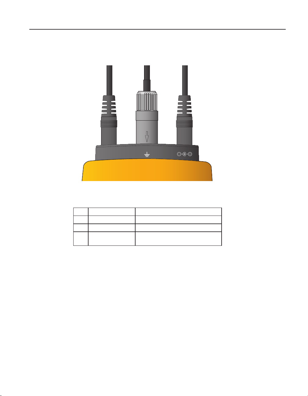
2.1 Setup
Figure 3
Input/Output Connections - 1523
Quick Start
Setup
Table 2 1523 Input/Output Connections
No. Name Description
1 Serial Serial interface connector
2 Connector, T1 Sensor Connector, Channel 1
4 Power External Power adapter connection
7
Page 16
1523, 1524 Reference Thermometer
Setup
RS232
30 V MAX
12
V DC
T1 T2
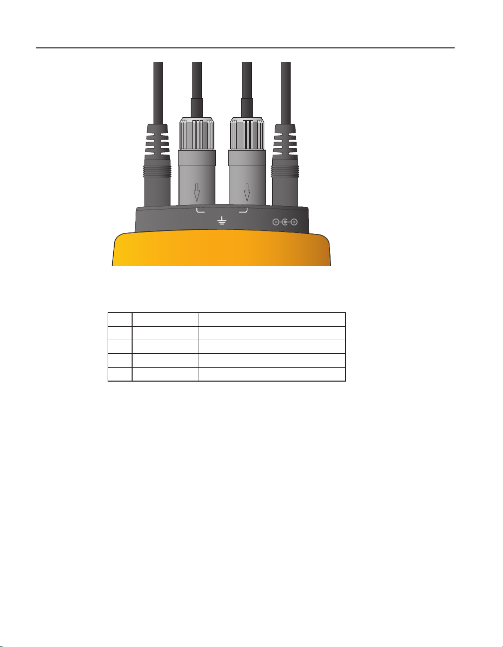
Figure 4
Input/Output Connections - 1524
Table 3 1524 Input/Output Connections
No Name Description
1 Serial Serial interface connector
2 Connector, T1 Sensor Connector, Channel 1
3 Connector, T2 Sensor Connector, Channel 2
4 Power External Power adapter connection
8
Page 17
Quick Start
Setup
RS232
1
30 V MAX
T1 T2
CALI BRATI ON
1524
THER MOMET ER
READ OUT
2
12
V DC
3
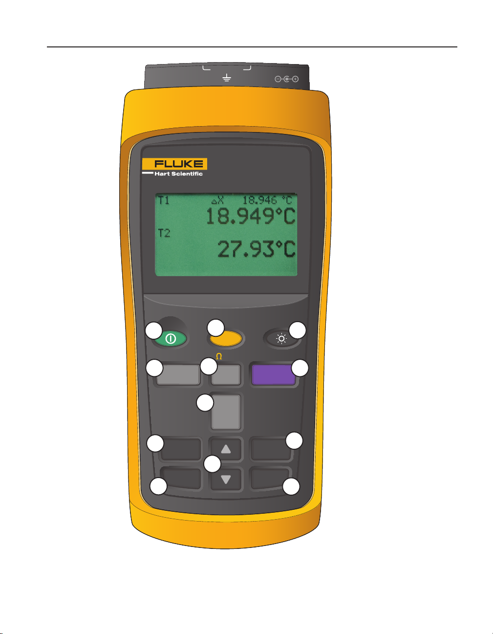
Figure 5
4
8
11
Keys
RESET
SAVE
RECALL
7
5
9
°C °
SETUP
TRENDmV
F
HOLDSTATS
HOMELOG
ENTER
NEXT
6
10
12
9
Page 18
1523, 1524 Reference Thermometer
Setup
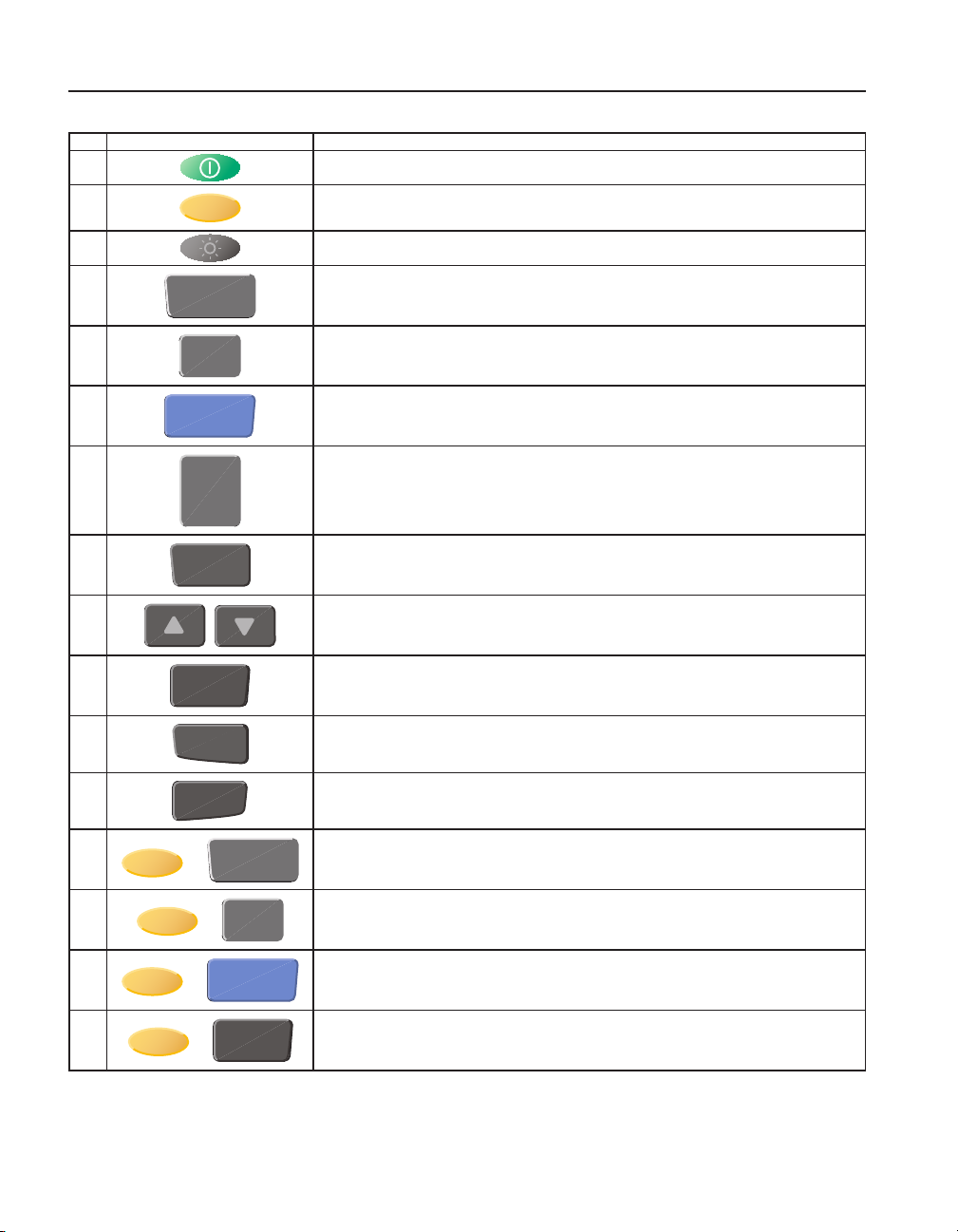
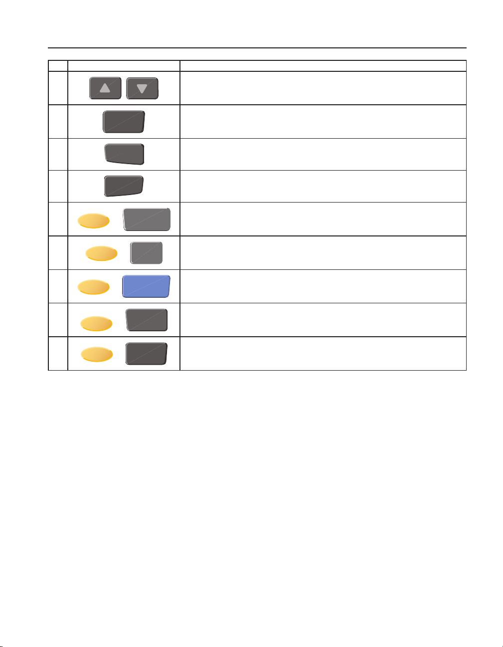
Table 4 1523 Key Functions
No Key Description
1 Power on or off
2 Yellow Second or Special Function Key
3 Turns the backlight on or off
4
5
6
7
8
9
10
11
12
STATS
°C °
HOLD
SETUP
SAVE
ENTER
RECALL
NEXT
F
1st Press: MAX, 2nd Press: MIn, 3rd Press: AVE, 4th Press: STD DEV
Units, °C/°F
1st press - Holds value on screen "-- HOLD --" across bottom of screen. 2nd press Releases Screen hold.
Enters setup menu, see menu structure
Saves measurement as a logged data point
Arrows increment or decrement selections in an active eld. In Graph Mode, Arrows change
the scale of the graph.
Selects highlighted selection, Saves a new selection.
1st Press - Enters Recall menu, 2nd Press - Exits Recall Menu
Moves down to next option on screen.
10
13
14
15
16
STATS
+
°C °
+
HOLD
+
ENTER
+
“RESET” - Resets Stats Data
“Ω mV” - Toggles from °C to Ω or Ω to °C (PRT, thermistor), °C to mV or mV to °C (TC)
F
“TREND” - Starts Graphing data
“HOME” Returns user to main screen
Page 19
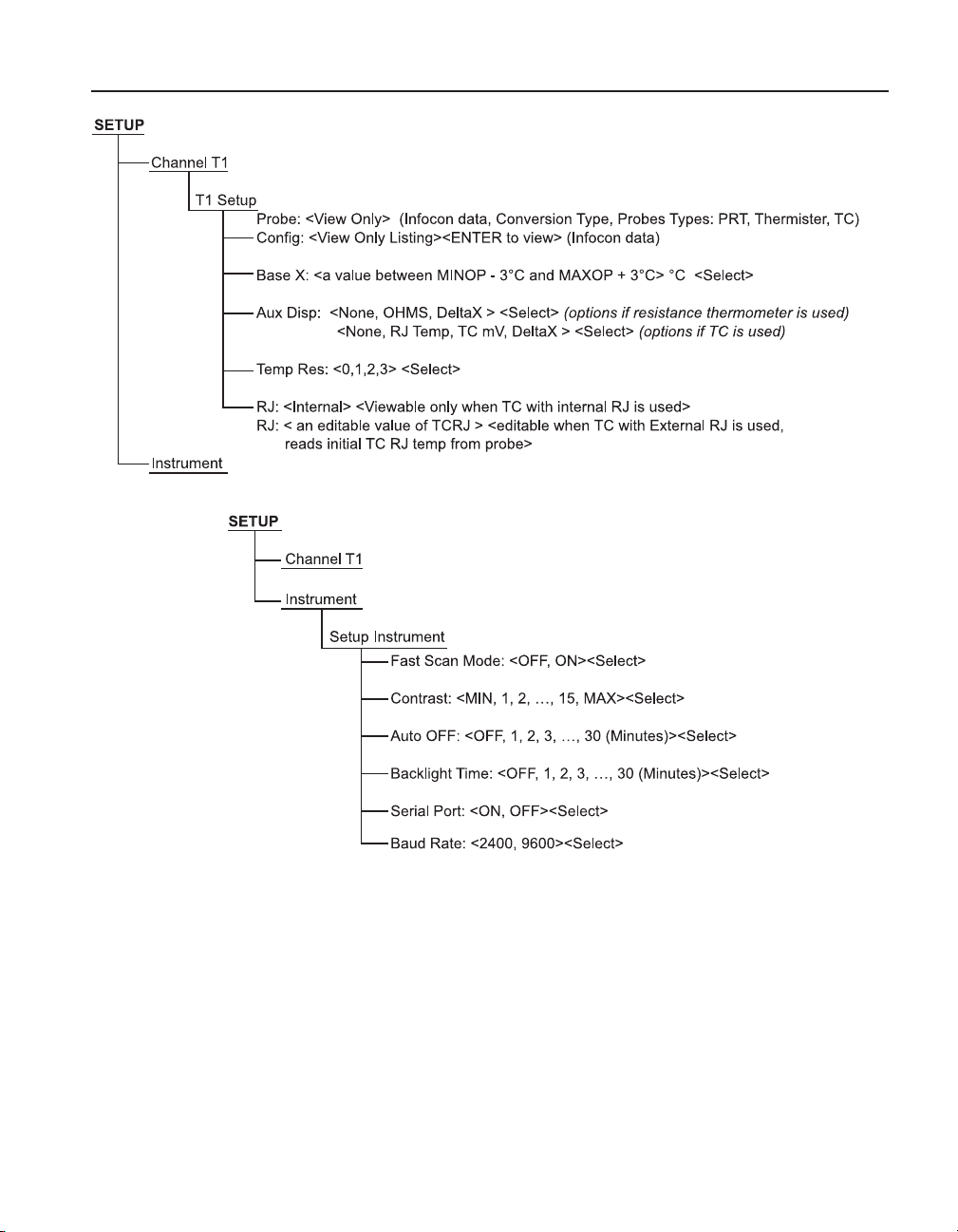
Figure 6 1523 Menu
Quick Start
Setup
Figure 7 1523 Menu (cont)
11
Page 20
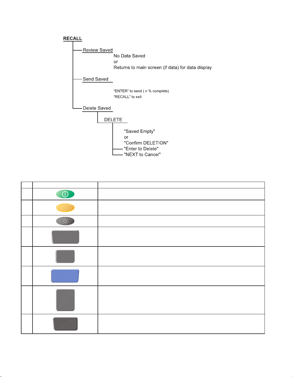
Figure 8 1523 Menu (cont)
Table 5 1524 Key Functions
No Key Description
1 Power on or off
2 Yellow Second or Special Function Key
3 Turns the backlight on or off
4
5
6
7
8
STATS
°C °
HOLD
SETUP
SAVE
F
1st Press: Max, 2nd Press: Min, 3rd Press: Ave, 4th Press: STD DEV
Units, °C/°F
1st press - Holds value on screen "-- HOLD --" across bottom of screen. 2nd press Releases Screen hold.
Enters setup menu, see menu structure
Saves measurement as a logged data point
Page 21
No Key Description
Quick Start
Setup
9
10
11
12
13
14
15
16
17
ENTER
RECALL
NEXT
STATS
+
+
+
+
+
°C °
HOLD
SAVE
ENTER
F
Arrows increment or decrement selections in an active eld. In Graph Mode, Arrows
change the scale of the graph.
Selects highlighted selection, Saves a new selection.
1st press - Enters Recall Menu, 2nd press - Exits Recall Menu
Moves down to next option on screen.
“RESET” - Resets Stats Data
“Ω mV” - Toggles from °C to Ω or Ω to °C (PRT, thermistor), °C to mV or mV to °C (TC)
“TREND” - Starts Graphing data
“LOG” - Log a series of measurements, see Auto Log in menu structure
“HOME” Returns user to main screen
13
Page 22
1523, 1524 Reference Thermometer
Setup
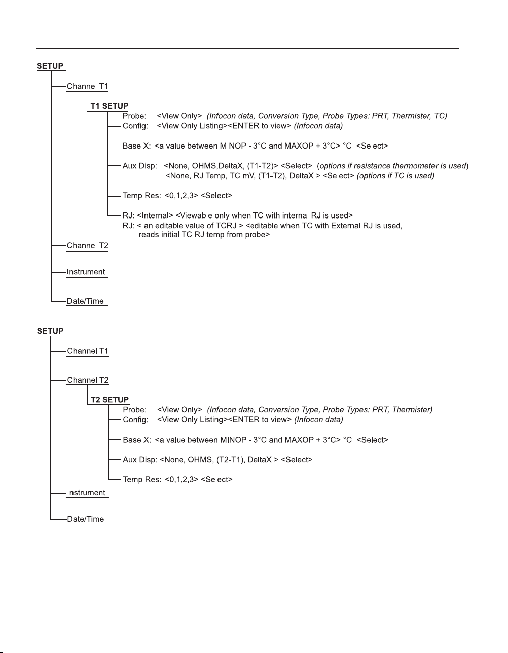
Figure 9 1524 Menu
Figure 10 1524 Menu (cont)
14
Page 23
Quick Start
Setup
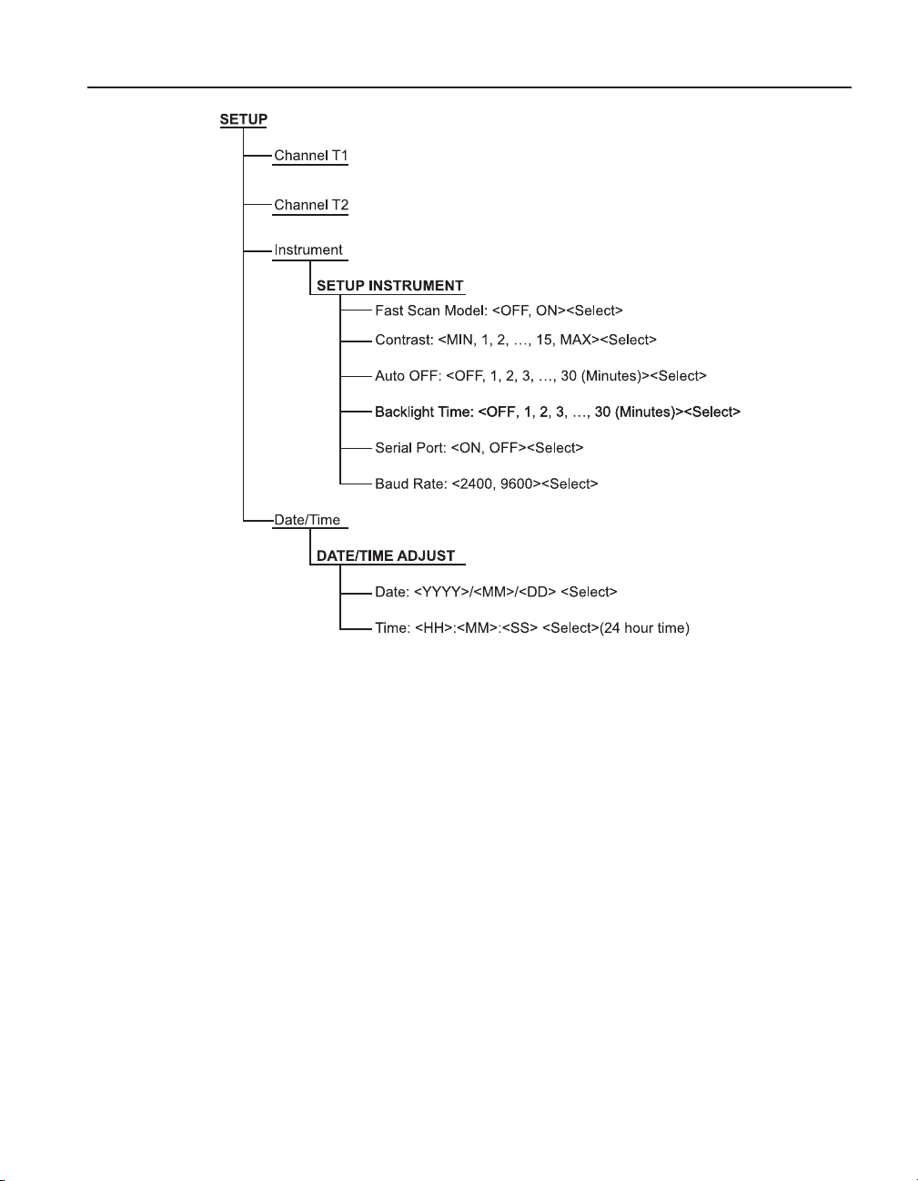
Figure 11 1524 Menu (cont)
15
Page 24
1523, 1524 Reference Thermometer
Setup
16
Figure 12 1524 Menu (cont)
Page 25
Quick Start
Specications
Figure 13 1524 Menu (cont)
Figure 14 1524 Menu (cont)
2.2 Specications
Specications are based on a one year calibration cycle and apply from 13 °C to 33 °C
unless stated otherwise. All specications assume a ve minute warm up period
17
Page 26

1523, 1524 Reference Thermometer
Specications
Table 6 General Specifications
Operating
Temperature†
Storage Temperature –20 °C to 70 °C
Operating altitude
Relative Humidity (%
RH operating without
condensation)
Vibration Random, 2g, 5–500 Hz
Power requirements 3 AA alkaline batteries 12 V dc universal
Size 96 x 200 x 47 mm (3.75 x 7.9 x 1.86
Weight 0.65 kg (1.4 lb)
Safety EN 61010-1:2001, CAN/CSA C22.2 No.
†
Environmental conditions for all specications: 13 °C to 33 °C
Table 7 Millivolt Measurement
Range Resolution Accuracy
–10 mV to 75 mV 0.001 mV ± (0.005 % + 5 µV)
Temperature Coefficient ( –10 °C to 13 °C, +33 °C to 60 °C):
± (0.001 %/°C + 1 µV/°C)
–10 °C to 60 °C
0 °C to 60 °C with ac adapter
10,000 meters above mean sea level
(2,000 meters with ac Adapter)
0 % to 90 % (non condensing)
power supply
inches)
61010.1-04
18
Table 8 Reference Junction Compensation
Thermocouple Reference Junction Compensation
Accuracy
± 0.20 C
Table 9 Ohms Measurement, RTDs
Ohms Range Accuracy ± Ω 4 Wire
0 Ω to 400 Ω ± (0.004 % + 0.002 Ω)
Temperature Coefficient ( –10 °C to 13 °C, +33 °C to 60 °C):
0.0008 %/°C + 0.0004 Ω
Excitation Current: 1 mA
Page 27
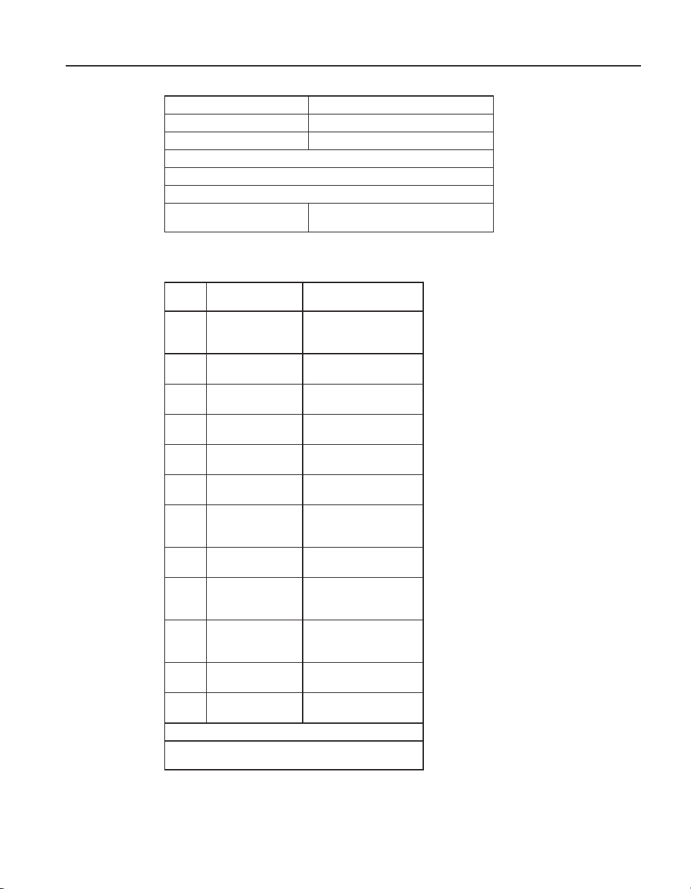
Table 10 Ohms Measurement, Thermistor
Ohms Range Accuracy ± Ω, 4 Wire
200 Ω to 50 kΩ ± (0.01 % + 0.5 Ω)
50 kΩ to 500 kΩ ± (0.03 %)
Temperature Coefficient ( –10 °C to 13 °C , +33 °C to 60 °C):
0.002 %/°C + 0.1 Ω (0 Ω to 50 kΩ)
0.06 %/°C + 0.1 Ω (50 kΩ to 500 kΩ)
Excitation Current: 10 µA (0 Ω to 50 kΩ) 2 µA (50 kΩ to
500 kΩ)
Table 11 Equivalent temperature accuracies derived from primary
specifications (Ω, mV)
Type Range
B 600 °C to 800 °C
800 °C to 1000 °C
1000 °C to 1800 °C
C 100 °C to 550 °C
550 °C to 2300 °C
E –200 °C to 0 °C
0 °C to 950 °C
J –200 °C to 0 °C
0 °C to 1200 °C
K –200 °C to 0 °C
0 °C to 1370 °C
L –200 °C to 0 °C
0 °C to 900 °C
M –20 °C to 0 °C
0 °C to 400 °C
400 °C to 1400 °C
N –200 °C to 0 °C
0 °C to 1300 °C
R –20 °C to 0 °C
0 °C to 500 °C
500 °C to 1750 °C
S –20 °C to 0 °C
0 °C to 500 °C
500 °C to 1750 °C
T –200 °C to 0 °C
0 °C to 400 °C
U –200 °C to 0 °C
0 °C to 400 °C
Resolution: 0.01 °
Note 1: Accuracies are based on internal Reference
Junction Compensation..
Measure
Accuracies (ITS-90)
0.85 °C
0.68 °C
0.57 °C
0.32 °C
0.71 °C
0.52 °C
0.22 °C
0.52 °C
0.23 °C
0.61 °C
0.24 °C
0.36 °C
0.23 °C
0.26 °C
0.25 °C
0.22 °C
0.72 °C
0.28 °C
1.09 °C
0.97 °C
0.49 °C
1.05 °C
0.95 °C
0.56 °C
0.60 °C
0.25 °C
0.54 °C
0.24 °C
Quick Start
Specications
19
Page 28

1523, 1524 Reference Thermometer
Specications
Table 12 Temperature, Thermocouples External Reference Junction
Type Range
B 600 to 800 °C 0.85 °C
800 to 1000 °C 0.68 °C
1000 to 1800 °C 0.57 °C
C 100 to 550 °C 0.32 °C
550 to 2300 °C 0.71 °C
E -200 to 0 °C 0.18 °C
0 to 950 °C 0.09 °C
J -200 to 0 °C 0.21 °C
0 to 1200 °C 0.12 °C
K -200 to 0 °C 0.31 °C
0 to 1370 °C 0.15 °C
L -200 to 0 °C 0.15 °C
0 to 900 °C 0.11 °C
M -20 to 0 °C 0.14 °C
0 to 400 °C 0.14 °C
400 to 1400 °C 0.14 °C
N -200 to 0 °C 0.48 °C
0 to 1300 °C 0.20 °C
R -20 to 0 °C 1.06 °C
0 to 500 °C 0.95 °C
500 to 1750 °C 0.48 °C
S -20 to 0 °C 1.03 °C
0 to 500 °C 0.93 °C
500 to 1750 °C 0.55 °C
T -200 to 0 °C 0.30 °C
0 to 400 °C 0.13 °C
U -200 to 0 °C 0.27 °C
0 to 400 °C 0.13 °C
Resolution: 0.01 °C
Note 1: Accuracies are based on external reference junction
compensation.
Measure Accuracies
(ITS-90)
20
Page 29
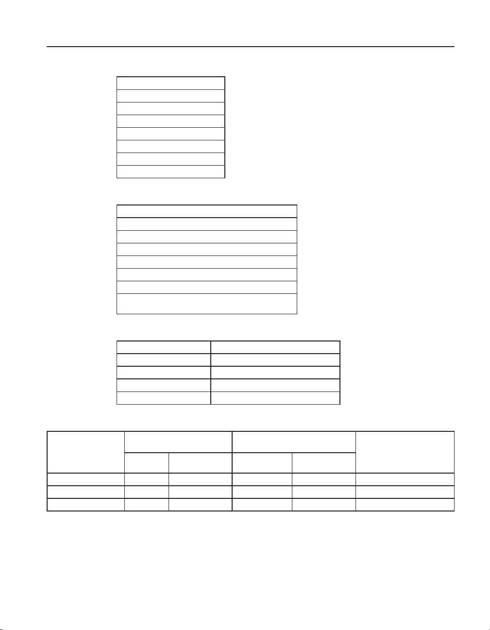
Table 13 Temperature, RTD Ranges and Accuracies (RTD-90)
Accuracy ± °C 4-wire Probe
± 0.011 at -100 °C
± 0.015 at 0 °C
± 0.019 at 100 °C
± 0.023 at 200 °C
± 0.031 at 400 °C
± 0.039 at 600 °C
Resolution: 0.001 °C (0.001 °F)
Table 14 Temperature, Thermistor
Accuracy @ °C
± 0.002 at 0 °C
± 0.003 at 25 °C
± 0.006 at 50 °C
± 0.014 at 75 °C
± 0.030 at 600 °C
Resolution: 0.001 °C (0.001 °F)
Based on a 10kΩ (at 25 °C) thermistor with a beta value
of 4000 Ω.
Quick Start
Specications
Table 15 Fast Scan Mode Specifications
Probe Type Times Normal specication
PRTs 0Ω to 400Ω 2
Thermocouples 2
Thermistors to 100K 5
Thermistors 100K to 500K 10
Table 16 Sample Interval per Channel in Seconds
Normal Mode
(sample rate set 1 second)
Probe Type
PRT 1s 1.3s 0.45s 0.9s PRT and PRT
Thermistor 1s 1s 0.3s 0.6s Thermistor and Thermistor
Thermocouple 1s 1s 0.3s 0.6s Thermocouple and Thermistor
Channels 1
and 2 Channel 1
Fast Scan Mode
(sample rate set to Auto)
Channels 1
and 2
Probe combination for two
channelChannel 1
21
Page 30

1523, 1524 Reference Thermometer
Specications
Table 17 Channel to Channel Differential Specifications
Probe Type Times Normal specication
T1 – T2 1
T1 – T2 Fast Scan Mode See Table “Fast Scan Mode
NOTE: Specication is for T1 – T2 < +/- 10 °C. For Like Probes only.
Accuracies do not include probe accuracies.
Specications”
22
Page 31

General Operation
DC Power Source
3 General Operation
This section explains the details of the operation of the 1523/24 reference thermometer
with its components and accessories.
3.1 Battery
The 1523/24 uses three (3) “AA” alkaline batteries that can power the instrument
for 20 hours without replacement. The batteries will discharge more quickly if the
backlight is used often. The battery icon will blink as the batteries approach depletion.
When the battery icon is blinking, the user should replace batteries immediately to
avoid affecting the accuracy of the instrument.
The batteries can be easily removed and replaced in the eld by following this
procedure:
1. Power the 1523/24 off and unplug the AC adapter from the unit.
2. Remove the yellow boot.
3. With the 1523/24 facing down, remove the screw and battery cover.
4. Remove the batteries.
5. Place new batteries into the unit.
6. Close the battery cover and replace the screw.
7. Replace the yellow boot.
Warning: Used batteries must be disposed of properly. Check your local
regulations for additional information. You may return used batteries to the
manufacturer. Never dispose of batteries in fire as this may result in explosion
with the possibility of personal injury or property damage.
3.2 DC Power Source
The DC power source provides power to the 1523/24 reference thermometer. The AC
adapter provided with the 1523/24 is intended to be used for this purpose. Use only
the AC adapter supplied with the instrument. The DC power source plugs into the DC
power input on the right side of the 1523/24.
23
Page 32

1523, 1524 Reference Thermometer
Probe
Figure 15 12V DC Power source Polarity
Warning: The AC adapter has circuits with high voltages inside that could
present danger of electric shock or fire if exposed. If the AC adapter is damaged
in any way or becomes hot, discontinue its use immediately, disconnect it from
any AC supply, and have it replaced. Do not attempt to open, repair, or continue
using a damaged or defective AC adapter
3.3 Probe
The probe is used to sense temperature. The 1523 is a single channel instrument and
can measure using one probe. The 1524 is a dual channel instrument and can measure
using two probes simultaneously. The probes attach to the 1523/24 using a Hart INFOCON probe connector that plugs into the top of the instrument. The probe connector
must be properly programmed with the correct characteristics of the probe for measurements to be accurate.
The 1523/24 can be used with various types of PRTs, Thermistors and Thermocouple
probes:
●
ITS-90 calibrated 25 Ω or 100 Ω PRT
●
Callender-Van Dusen calibrated 100 Ω PRT,
●
Steinhart-Hart thermistor R(T) polynomial; nominal R (25°C) 2KΩ to 100KΩ.
●
Types B, C, E, J, K, L, M, N, R, S, T, U Thermocouples
The 1523 can measure PRT probes having 4 wires, thermistors, or thermocouples. The
1524 can measure PRT probes having 4 wires, and thermistors on either channel 1 or
channel 2, and can measure thermocouples on channel 1 (only). Channel 2 on the 1524
cannot be used with thermocouples.
24
Page 33

General Operation
Probe Lock Function
3.3.1 Internal or External reference junction compensation may be used with this instrument.
3.3.2 TC Internal Reference Junction
With internal reference junction compensation, the temperature of the Thermocouple
connection is measured automatically and used to calculate the absolute temperature
of the thermocouple. The infocon reference junction parameter must be programmed
to Internal, and the external temperature parameter in the infocon will be ignored.
3.3.3 TC External Reference Junction
With External Reference junction compensation, the reference junction is held at a
known xed temperature. The value of the xed temperature reference is used to
calculate the absolute temperature of the thermocouple.
In this method, the reference junction is created externally and copper wires connect
the reference junction to the 1523/24. The reference junction is placed in an ice bath
or other temperature source that has a precisely known and stable temperature. This
technique offers improved accuracy but is less convenient because of the more complicated connection scheme and the requirement of a precision temperature source.
The external reference temperature parameter and the external reference junction
parameter must be set in the infocon connector prior to using this method.
Temperature is generally sensed at the tip of the probe. To get an accurate temperature
measurement the probe sheath should be well immersed, with adequate depth and t
into the medium to be measured.
Caution: Probes are fragile devices that can be easily damaged by mechanical
shock, overheating, and absorption of moisture or fluids in the wires or hub.
Damage may not be visibly apparent but nevertheless can cause drift, instability,
and loss of accuracy. Observe the following precautions:
●
Do not allow probes to be dropped, struck, bent or stressed.
●
Do not overheat probes beyond their recommended temperature range.
●
Do not allow any part of the probe other than the sheath to be immersed in uid.
●
Do not allow the probe hub or wires to be exposed to excessive temperatures.
●
Keep the probe wires clean and away from uids.
3.4 Probe Lock Function
The 1523 may be locked for exclusive operation with a specic probe, for quality control purposes, and each channel of the 1524 may be locked with its own unique probe.
Locking the probe also prevents use with other readouts, until the probe is unlocked.
To set the probe lock, plug in the probe to the channel that you want to lock it to. First
send the unit password enable command, SYST:PASS:CEN XXXX (where xxxx is the
unit password) through the serial port using the 9940 software or a terminal program.
25
Page 34

1523, 1524 Reference Thermometer
INFO-CON Connector
Then send the serial command CALx:DEV:LOCK 1 to the unit, where x is the channel
that the probe is connected to.
To unlock a probe send the SYST:PASS:CEN XXXX (where xxxx is the unit password). Then send the command, CALx:DEV:LOCK 0
Any unit can unlock a locked probe. The 9940 software can read in a locked probe's
data.
If the probe lock is on and a different probe is attached to the unit or channel the display will show “LOCKED”. Measuring is disabled.
If probe lock is off, the instrument can be used with any probe. Refer to the Digital
Communication Interface section of this manual
3.5 INFO-CON Connector
The probe(s) connects to the top of the 1523/24 reference thermometer using a Hart
INFO-CON connector. The probe connector will t snugly and lock into place when it
is fully inserted. The connector includes a memory device that stores the unique characteristics of the probe, allowing the instrument to measure temperature accurately.
Generally the probe will be purchased with the connector attached and programmed
by the factory. Connectors can be purchased separately and installed on probes by the
user. The INFO-CON can be programmed directly from the 1523/24 by authorized
personnel using the serial port commands or the 9940 software (see Section 6, Digital
Communication Interface on page 43).
If it is necessary to connect an INFO-CON connector to a probe in the eld, follow the
diagram below for connecting the wires of the probe to the connector terminals. Before opening the INFO-CON case, be sure to be grounded with an ESD strap to avoid
damaging the memory chip. If a shield wire is present it should not be connected.
26
Page 35

General Operation
INFO-CON Connector
Figure 16 Probe wiring diagrams
27
Page 36

Page 37

Display Functions and User Interface
4 Display Functions and User Interface
This chapter discusses in detail how to operate the Reference Thermometer using the front panel keys and liquid crystal display (LCD). This includes reading
temperature(s) in °C or °F, viewing statistics, using the auxiliary display for differential temperature (T1-T2) or electrical readings (Ω, mV), capturing up to 25 discrete
data readings with statistics, logging up to 15,000 readings at selected time intervals,
and conguring the communication interface. Refer to the full menu structure diagram
in the previous section.
4.1 Main Screen
The LCD on the front panel allows direct viewing of the temperature readings, auxiliary reading, statistics (MIN, MAX, AVE, and STDDEV), or a graphical representation
of the temperature reading over time with the temperature or stats for the temperature
above the graph. The temperature displayed is either in °C or °F, and is easily changed
by pressing the °C °F key on the front keypad. The main displayed value is the temperature reading from the probe. The auxiliary reading is the value displayed based
on the user options from the SETUP menu and includes the reading in ohms, mV,
Delta X, T1 – T2, or T2 – T1, or the reference junction temperature if a thermocouple
is used. The main screen will also show the menu items and selections when a menu
related key is pressed. The following sections describe the keys and menu functions.
HOLD
4.2 STATS
The STATS key allows the user to view the minimum, maximum, average, and the
standard deviation of the readings on each channel. When using this feature, press the
STATS key to enter this mode. Press the STATS key again to toggle through the statistics options, MAX, MIN, AVE, and STDDEV. The results of the selection are shown
in the main numeric display. If the user enters into the graphing mode, the results of
the selection will be displayed across the top of the graph in the smaller characters.
When using this feature on the 1524 dual channel instrument, both of the channels
will display the same selection, MIN, MAX, AVE, or STDDEV. The user is unable to
select different statistics options for each channel. Press the RESET or HOME keys to
exit the STATS mode.
4.3 °C °F
The °C °F key allows the user to quickly change between units. In the main numeric
screen, this key will toggle the units in both the main and auxiliary display values. In
graphing mode, the unit change will cause the graph to refresh. Select units prior to
starting a graphing session. Units are displayed and recorded with temperature readings, auxiliary readings, and logged data.
4.4 HOLD
This mode is identied by “HOLD” which appears on the bottom center of the display.
29
Page 38

1523, 1524 Reference Thermometer
SETUP
In this mode the data stored and displayed last remains on screen, this includes statistics information. Press the HOLD or HOME keys to exit the hold mode.
4.5 SETUP
The SETUP key accesses the SETUP Menu and allows access to Channel T1 Setup
submenus, Channel T2 Setup submenus (1524 only), Instrument setup, and the Date/
Time (1524 only) submenus. The submenus allow the user to congure the instrument
and its system parameters.
4.5.1 Channel T1
Select the Channel T1 submenu by pressing the ENTER key. This menu allows the
user access to view the probe data from the INFO-CON connector and to setup the
auxiliary display for channel T1.
4.5.1.1 Probe
This is a read only eld; it tells the user the probe and/or the conversion type used with
the related probe.
4.5.1.2 Cong
This is a read only screen, when accessed by pressing the ENTER key, the user can
view all of the setup information retained in the INFO-CON connector. This information tells the user the conversion type, serial number, calibration date, all of the coefcients used for this probe, reference junction type (internal or external) if the probe is
a thermocouple, and the Min and Max temperatures allowed for the probe.
30
4.5.1.3 Base X
This is the reference value used by the DeltaX function in the auxiliary display. DeltaX calculates the difference between the current reading and Base X.
4.5.1.4 Aux Displ
This is the Auxiliary display selection. In addition to temperature on the main numeric
output, the user may choose to display an auxiliary measurement for channel T1. For
a resistance thermometer, the user may select to display Ohms, DeltaX, (T1-T2), or
None.
If this display feature is for a thermocouple, the user may choose to display RJ Temperature, mV, (T1-T2), DeltaX or None.
4.5.1.4.1 Ohms
This mode is identied by “W” along the top of the screen. In this mode, the resistance
in Ohms for the temperature measurement appears on the top of the display. This option is available when the selected channel is reading PRTs or thermistors.
Page 39

4.5.1.4.2 mV
This mode is identied by “mV” along the top of the screen. In this mode, the voltage
reading in mVs for the temperature measurement appears on the top of the display.
This option is available when the selected channel is reading thermocouples.
4.5.1.4.3 RJ Temp
This mode is identied by “RJ” along the top of the screen. In this mode, the reference
junction temperature reading appears on the top of the display. This option is available
when the selected channel is reading thermocouples and the reference junction is set to
Internal.
4.5.1.4.4 DeltaX
This mode is identied by “DX” along the top of the screen. In this mode, the difference (delta) between the measurement and a previously stored reference value (Base
X) appears on the top of the display.
4.5.1.4.5 T1-T2
This mode is identied by “DT” along the top of the screen in the T1 row. In this
mode, the difference between the channel T1 reading and the channel T2 reading is
shown on the top of the display in the rst row. This mode is only available in model
1524.
Display Functions and User Interface
SETUP
4.5.1.4.6 None
In this mode, nothing is displayed in the auxiliary display area.
4.5.1.5 Temp Res
The Temperature Resolution may be changed from 0 to 3 decimal places when using
a resistance thermometer. A maximum of two decimal places is allowed if using a
thermocouple probe.
4.5.1.6 RJ
Thermocouple reference junction compensation may be either internal or external,
depending whether the thermocouple has an external reference junction or not. Reference junction temperatures for the external type may be entered through the display.
Reference junction temperatures for internally compensated thermocouples can be
shown on the auxiliary display. The reference junction type will be identied in the
INFO-CON connector for the specic thermocouple and can only be edited through
the serial port.
4.5.2 Channel T2 (1524 Only)
Select the Channel T2 submenu by pressing the ENTER key. This menu allows the
user access to view the probe data from the INFO-CON connector and to setup the
31
Page 40

1523, 1524 Reference Thermometer
SETUP
auxiliary display for Channel T2. Channel T2 is only used for PRTs and thermistors.
This channel can not be used for thermocouples. This Submenu is available in model
1524 only.
4.5.2.1 Probe
This is a read only eld; it tells the user the probe and/or the conversion type used with
the related probe.
4.5.2.2 Cong
This is a read only screen, when accessed by pressing the ENTER key, the user can
view all of the setup information retained in the INFO-CON connector. This information tells the user the conversion type, serial number, calibration date, all of the coefcients used for this probe, and the Min and Max temperatures allowed for the probe.
4.5.2.3 Base X
This is a reference value that may be stored in the unit for use as a comparison or difference value from the current reading when using the DeltaX auxiliary display.
4.5.2.4 Aux Displ
This is the Auxiliary display selection. In addition to temperature on the main numeric
output, the user may choose to display an auxiliary measurement for channel T2. For
a resistance thermometer, the user may choose to display Ohms, DeltaX, (T2-T1), or
None.
4.5.2.4.1 Ohms
4.5.2.4.2 T2-T1
4.5.2.4.3 DeltaX
32
This mode is identied by “W” along the top of the screen. In this mode, the resistance
in Ohms for the temperature measurement appears on the top of the display. This option is available when the selected channel is reading PRTs or thermistors.
This mode is identied by “DT” along the top of the screen in the T2 row. In this
mode, the difference between the Channel T2 reading and the Channel T1 reading is
shown on the top of the display. This mode is only available in Channel T2 on model
1524.
This mode is identied by “DX” along the top of the screen. In this mode, the difference (or delta) between the measurement and a previously stored reference value
(Base X) appears on the top of the display.
Page 41

4.5.2.4.4 None
In this mode, nothing is displayed in the auxiliary display area.
4.5.2.5 Temp Res
The Temperature Resolution may be changed from 0 to 3 decimal places if using a
resistance thermometer, or a maximum of two decimal places if using a thermocouple
probe.
4.5.3 Instrument
The instrument menu allows the user access to the serial port setup, unit Auto-Off
timer, backlight timer, contrast and the fast scan rate mode. The Auto-Off timer and
backlight timer are power saving settings for use when operating on battery power.
4.5.3.1 Fast Scan Mode
This mode allows the user to increase the sample rate in the instrument. When this
mode is used, the sample rate is increased at the expense of the accuracy. The instrument specications are only guaranteed when the Fast Scan Mode is turned off. Refer
to alternate specications for operating in Fast Scan mode. This setting is not stored in
the memory and is reset to off at power up.
Display Functions and User Interface
SETUP
4.5.3.2 Contrast
This is an incremental setting selection that enables the user to change the screen
contrast. An increase in value results in a darker contrast. A decrease in value results in
a lighter contrast.
4.5.3.3 Auto-Off
This timer setting tells the unit how long to stay on before shutting down. Allowable
settings Range from 1 to 30 minutes or the user may turn this feature Off. If the unit
turns off, this feature will terminate the graphing mode and auto logging mode when
shutting down. The user will need to press the POWER key in order to restart the unit.
4.5.3.4 Backlight Time
This timer setting tells the unit how long to keep the back light illuminated before
shutting down. Allowable settings range from 1 to 30 minutes or the user may turn this
feature Off.
4.5.3.5 Serial Port
This feature allows the user to turn the serial port On or Off. This is a battery saving
feature and is recommended when operating on battery power and when direct uploading to a PC is not required. Data may be gathered in the Demand Log or Auto-Log
modes prior to turning on the serial port and uploading the information.
33
Page 42

1523, 1524 Reference Thermometer
SAVE
4.5.3.6 Baud Rate
This feature allows the user to change the baud rate from 9600 (default) or 2400 baud.
4.5.3.7 Date/Time
This feature allows the user to change or adjust the Time and Date. The time and date
is recorded on all Log les saved. This feature is only available on model 1524.
4.5.3.7.1 Date
The date feature allows the user to adjust the month, day and year in an YYYY/MM/
DD format. The date can be adjusted by using the up and down arrow keys while
in the date eld, and pressing the ENTER key to save the change. The curser will
highlight the year <YYYY> eld when entering into this screen. Use the up and down
arrow keys to adjust the year. Press the ENTER key to save the change and advance to
the month <MM> eld. Adjust the months in the same manner and press the ENTER
key when complete. This will advance the curser to the next eld, days <DD>. Change
the days eld to the correct day in the same manner and press the ENTER key when
complete. This feature is only available on model 1524.
4.5.3.7.2 Time
The time feature allows the user to adjust the HH/MM/SS in 24 hour format. The time
can be adjusted by using the up and down arrow keys while in the time eld, and then
pressing the ENTER key to save the change. The curser will highlight the hour <HH>
eld when entering into the time elds from the date elds. Use the up and down arrow keys to adjust the hour. Press the ENTER key to save the change and advance to
the min <MM> eld. Adjust the minutes in the same manner and press the ENTER
key when complete. This will advance the curser to the next eld, seconds<SS>.
Change the seconds eld to the correct second in the same manner and press the ENTER key when complete. This feature is only available on model 1524.
34
4.6 SAVE
A point is saved into the demand log when the SAVE key is pressed while in the numeric or graphic display mode. Up to 25 points may be stored using the demand log.
When the SAVE key is pressed, the bottom row of the display will indicate that a save
has occurred with a tag ID “SAV01” (followed by a date and time if model 1524). If
there are 25 points already stored, SAV FULL (save full) will be displayed for 3 seconds and no new data will be recorded.
4.7 ARROWS, UP, DOWN
The up and down arrow keys allow the user to select options within a eld indicated
by an up and down arrow indicator to the right or left of the eld.
Page 43

4.8 ENTER
The ENTER key is used to select a menu option, accept a setting change, conguration change, or enable a logging session.
4.9 RECALL
The 1523/24 has a Demand Log that stores up to 25 readings that may be displayed on
screen or sent out the serial port to a computer. The RECALL menu allows the user to
review, delete, or send demand log data out the serial port.
The 1524 has an Auto-Log with the added capability of storing up to 15,000 readings
with a time and date stamp on each reading. The readings can be sent to a computer or
deleted using this menu.
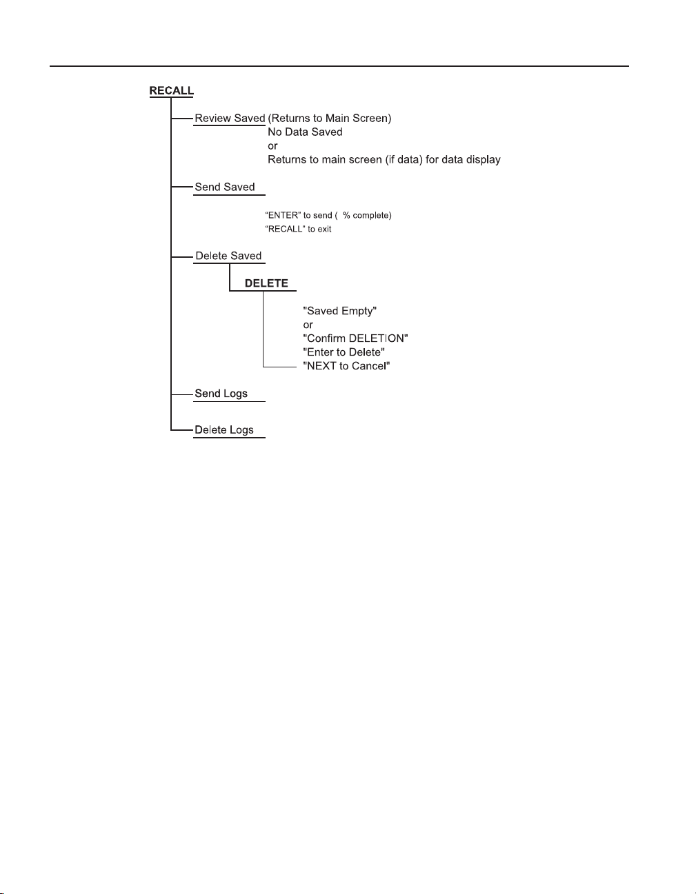
4.9.1 Review Saved
This menu displays one of up to 25 saved readings on main screen for review. The
display shows channel, auxiliary display value, main display value, tag id and time
stamp if model 1524. The user can scroll through each log by pressing the up and
down arrow keys. The user can exit this review mode by pressing the RECALL or the
HOME (SHIFT + ENTER) keys.
4.9.2 Send Saved
This feature sends the entire demand log out the serial port to a computer. When all of
the data is sent, the display will show “100%” to the right of the Send Saved command
selection to indicate that the send function is complete. This does not affect the stored
data. Refer to the Demand Log, and Digital Communications Interface section of this
manual for more information.
Display Functions and User Interface
RECALL
4.9.3 Delete Saved
This feature allows the user to delete data les saved in the Demand Log. The user
may delete a specied le or all les. Use the Up and Down arrow keys to select the
le to delete. The instrument default is used to delete all les. The user can exit this
menu and return to the main display by pressing the RECALL or HOME (SHIFT +
ENTER) key(s).
4.9.4 Send Logs
This feature allows the user to send logged data les out the serial port to a computer.
In order to use this feature the user must turn the serial port on, and set the baud rate
to the appropriate setting. Refer to Section 5.2, AUTO-LOG on page 39, and Section
6, Digital Communication Interface on page 43for more information. This feature is
available on model 1524 only.
35
Page 44

1523, 1524 Reference Thermometer
NEXT
4.9.5 Delete Logs
This feature allows the user to delete logged data les. The user may delete a specied
le identied by the Tag ID, or all les. Use the up and down arrow keys to select the
le to delete. The instrument default is to delete all les. The user can exit this menu
and return to the main display by pressing the RECALL or HOME (SHIFT + ENTER)
key(s). This feature is available on model 1524 only.
4.10 NEXT
The NEXT key is used to move from eld to eld in the menu.
4.11 SHIFT
This feature allows the user to use second function keys (identied in yellow) on the
keypad. Following a press of the shift key, “SHIFT” will be displayed on the lower
right side of the display. When in the “TREND” mode with a graph displayed, the
“SHIFT” will be displayed on the upper left area of the display. Pressing the “SHIFT”
key a second time eliminates the second function request.
4.12 RESET
The RESET key (SHIFT + STATS) is used to exit the STATS mode. Upon exiting
the STATS mode the minimum, maximum, average and standard deviation values are
reset.
36
4.13 Ω mV
The Ω mV key (SHIFT + °C °F) switches the main numeric display from degrees to
ohms/mV or ohms/mV to degrees. This feature allows the user to select between the
reading in base units (ohms or millivolts) and the reading converted to temperature.
4.14 TREND
The TREND key (SHIFT + HOLD) switches from numeric to graphic mode, or from
graphic to numeric mode. This feature provides the user with a convenient visual display of temperature over time by graphing the data in a temperature vs. time plot. This
may be used to assess settling time, stability, disturbances, or oscillations. This feature
is affected by the Auto-Off function. If the Auto-Off function is used and the unit turns
off during graphing, the graph will be terminated and the unit will restart in numeric
mode. It is recommended that the Auto-Off function be turned off before starting a
graphing session.
The time scale is displayed on the horizontal axis and is not adjustable. The time scale
is xed at 6 seconds per reading, allowing up to 10 minutes of data to be shown on the
graph. When the graph extends to the far right of the screen, the graph will scroll to
the left about 25% of the screen and continue plotting.
The temperature scale is displayed on the vertical axis and is adjustable up to 4 orders
of magnitude. The display range is shown on the left side of the vertical axis and is ad-
Page 45

Display Functions and User Interface
LOG
justed using the UP and DOWN ARROW keys to increase or decrease the scale range.
The available range selections are +/- 0.01, +/-0.1, +/-1.0, +/- 10.0 °C. The vertical
scale center is calculated automatically and displayed.
The graphing function may be used on models 1523 and 1524. The 1523 will always display Channel T1. When using the 1524 instrument, Channel T1 is selected
by default, the user may select between Channel T1 and Channel T2 by pressing the
“NEXT” key. In this mode, data for both Channel T1 and Channel T2 graphs are maintained simultaneously. Only one channel may be displayed at a time while the other
channel is held in memory. When a channel is switched, the graph is replaced with
data from the new channel.
While in the graphing mode, the channel being displayed is shown on the top left area
of the display, ‘T1” or “T2”. The top right area of the display shows the statistical
option, followed by the statistical value for the displayed channel in numeric format.
The most recent temperature measurement is displayed in numeric format above the
graph and just below the stats value. The statistical option selection may be changed
by pressing the “STATS” key until the desired option (MIN, MAX, AVE, or STD)
appears on the display. Note: Standard deviation will be shown on the screen in this
mode as STD rather than the usual STD DEV.
The graph is cleared when the display mode is changed to or from a numeric format,
or if the temperature units are changed. In addition, entering in the SETUP Menu will
cause the graph to refresh.
4.15 LOG
The Auto-Log feature allows the user to setup data collection and storage on both
channels. This menu selection allows the user to setup the interval of the logged data,
a tag or identication label, see the available memory for storage, and session start &
stop. This Auto-Log feature is only available in model 1524.
The Auto-Log feature is affected by the Auto-Off function. If the Auto-Off function is
used and the unit turns off during a logging session, the logging session will be terminated and the unit will restart with the Auto-Log turned off. It is recommended that the
Auto-Off function be turned Off before starting a logging session.
4.15.1 Free
This feature indicates the amount of memory available for storage, in terms of %
memory unused. It also indicates how many bytes of memory are available for use.
4.15.2 Interval
This feature allows the user to select the interval used by the processor to take new
data. The available selections are Auto, 1, 2, 5, 10, 30 and 60 seconds If logging with
a model 1524 using two active probes and a 1 second interval, a second of data will be
skipped approximately every three seconds in order to have unique values in every set
of stored data. When the unit is in Auto interval sampling, the Fast Scan Mode Specications apply. Refer to Table 15 on page 21, Fast Scan Mode Specications and Table
16 on page 21, Sample Interval per Channel in Seconds
37
Page 46

1523, 1524 Reference Thermometer
HOME
4.15.3 Tag
This is a label attached to the stored data set. The tag name may be changed by the
user using the serial interface port. This name can be 8 alpha numeric characters long.
4.15.4 Session
This feature is used to start or stop logging sessions. Only the available condition
(START or STOP) can be selected.
4.16 HOME
The HOME key (SHIFT + ENTER) allows the user to return to the main screen from
anywhere in the menu.
38
Page 47

5 LOGS
There are two log features associated with models 1523/1524, the Demand Log and
the Auto-Log. Both the 1523 and 1524 have a demand log that stores up to 25 readings. The 1524 has an Auto-Log that can store up to 15,000 readings at specied intervals. The Auto-Log feature is affected by the Auto-Off function. If the Auto-Off function is used and the unit turns off during a logging session, the logging session will be
terminated and the unit will restart with the Auto-Log turned off. It is recommended
that the Auto-Off function be turned off before starting an Auto logging session.
5.1 DEMAND LOG
This feature is used to log and recall up to 25 points. A point is logged using the SAVE
key. Logged data is saved in memory and is retained after the unit is turned off. The
data can be uploaded to a computer using the Send Saved command in the RECALL
Menu, or by remote commands issued through the serial port. Refer to the Digital
Communications Interface section of this manual for more information on the serial
commands.
Each logged data point contains the following data:
Current reading with units of measure
Current statistics, including maximum, minimum, average, and standard
deviation.
User selected secondary readings, including units.
Time stamp including year, month, day, hour, minute and second (model 1524
only).
LOGS
AUTO-LOG
5.2 AUTO-LOG
This feature is used to log and store up to 15,000 points. A point is logged on a predetermined frequency based on the LOG Menu settings. Logged data is saved in memory
and is retained after the unit is turned off. The data can be uploaded to a computer
using the Send Logs command in the RECALL Menu, or by remote commands issued
through the serial port. Refer to the Digital Communications Interface section for more
information on the serial commands.
The LOG key allows the user to access the LOG setup menu. The Log menu allows
the user to setup the data collection interval, start a log with a specied Tag ID, see the
available memory, and START or STOP a logging session. The RECALL menu allows
the user to delete, or send log data out the serial port.
Refer to the Digital Communications Interface section for information on changing
Tag IDs or using the computer interface.
5.2.1 Auto-Log Operation
A log session is congured and started or stopped by pressing the LOG key (SHIFT +
SAVE). The following screen is displayed:
Free: nn% rrrrr
Interval: tt sec. (or Auto)
39
Page 48

1523, 1524 Reference Thermometer
AUTO-LOG
Tag: vv, xxxxxxxx *
“yy/mm/dd hh:mm:ss” or “No Data”
Session: START (or STOP)
Where:
Free: indicates the percentage of unused memory (nn), and the total number of records
that can be stored before it becomes full (rrrrr), and automatically stops.
Interval: is the logging interval (tt) expressed in seconds. The choices are Auto, 1,
2, 5, 10, 30, and 60. 10 seconds is the default for a new log. Note: When the unit is
Auto interval sampling, the Fast Scan Mode Specications apply. Refer to Table 15 on
page 21, Fast Scan Mode Specications and Table 16 on page 21, Sample Interval per
Channel in Seconds
Tag: is an alpha-numeric identier (vv) from 1 to 25, followed by a Tag ID (xxxxxxx).
The default Tag ID names are DATA_01 to DATA_25 or the user specied eight
character tag name. If the tag has stored data, an asterisk (*) will follow the tag name
and the following line will contain the time stamp (Date followed by Time). If the tag
contains no data, “No Data” will be shown on the line following the Tag name.
Note: the user specified Tag can only be updated through serial communications
through the serial port. Refer to Section 6, Digital Communication Interface on page
43.
Session: START will be displayed when logging is not in use, STOP will be displayed
when logging is in use.
If logging is not in use when Auto-Log is selected, the user may change the interval
and Start the logging session. If a logging session is in use, the user may choose to
stop the session; no other actions may be performed by the user in this menu window.
The user may exit this screen without performing an action by pressing the LOG key
(SHIFT + SAVE) or the HOME key (SHIFT + ENTER).
Once an Auto-Log is started, the present primary value and the units for each channel
in use are stored at the selected interval. The lower line on the main screen shows the
log status as follows:
LOG n hh:mm:ss
Where n is the number or data points currently logged into the selected Tag ID, and
hh:mm:ss is the elapsed time since the log session started.
The update is in the selected interval of the logging session. For example, if the session has a 10 second log interval, the update on the main screen will also be in 10
second intervals.
When the log storage is full, the lower line on the main screen will change to “LOG
Full” and will remain until the user turns off the logging session by pressing the LOG
key (SHIFT + SAVE) and pressing ENTER to stop the session.
40
Page 49

Note: If logging with a model 1524 using two active probes and a 1 second interval,
a second of data will be skipped approximately every three seconds in order to have
unique values in every set of stored data. When the unit is in Auto interval sampling,
the Fast Scan Mode Specifications apply. Refer to Table 15 on page 21, Fast Scan
Mode Specifications and Table 16 on page 21, Sample Interval per Channel in Seconds
5.2.2 Sending Auto Log Data to a Computer
The data from one or all tags can be sent out the serial port to a computer. In order to
send data out the serial port, the instrument must be in the main numeric screen, and
the logging session must be turned off (no logging or graphing).The user may then
press the RECALL key and press the NEXT key to highlight the Send Logs selection,
then press ENTER.
The next menu screen will allow the user to select a specic Tag ID to download or
choose to down load All tags. Use the up and down arrow keys to make selection.
5.2.3 Data Upload Format
Each data line includes the default or the user dened Tag ID, the channel number,
the primary value with units, and time and date. Note: The time stamp is available on
model 1524 only. If only one channel is active during the logging session, only the
data for the active channel will be will be sent through the serial port. If both channels
are active, the records for each channel will alternate on the output. The output format
is shown in the following example for a two channel output:
DATA_25,1, 22.676, C, 15:19:42,2008-05-24
DATA_25,2, 23.245, C, 15:19:44,2008-05-24
DATA_25,1, 23.220, C, 15:19:46,2008-05-24
DATA_25,2, 23.260, C, 15:19:48,2008-05-24
DATA_25,1, 22.765, C, 15:19:50,2008-05-24
DATA_25,2, 23.263, C, 15:19:52,2008-05-24
Each data eld is comma delimited, and each record is terminated with a carriage return (CR) and a new line (LF) command. For more information on the serial interface
protocols, see the Digital Communications Interface section.
LOGS
AUTO-LOG
5.2.4 Deleting Auto Log Data
This feature allows the user to delete logged data les by selecting Delete Logs in the
RECALL menu. The user may delete a specied le, identied by the Tag ID, or select
All les. Use the Up and Down arrow keys to select the le to delete. The instrument
default is to delete All les. Once the user has selected the data les to delete, press
ENTER to delete the le. The instrument will request the user to conrm deletion and
the user must press ENTER again to delete, or press NEXT to cancel the request. The
user can exit this menu and return to the main display by pressing the RECALL or
HOME (SHIFT + ENTER) key(s) at any time. This feature is available in model 1524
only.
41
Page 50

Page 51

Digital Communication Interface
6 Digital Communication Interface
The 1523/24 handheld readout is capable of communicating with and being controlled
by an external device through the RS-232 digital interface.
With a digital interface, the instrument may be connected to a computer. This allows
the user to obtain measurement data and control operating conditions. The RS-232 serial interface allows serial digital communications over fairly long distances. With the
serial interface, the user may access any of the functions, parameters and settings discussed in this section. The 9940 software that came with the unit is available to assist
in the communications interface. Refer to the documentation included on the software
CD for additional information.
Special Note on Using grounded and bare junction thermocouples with
RS-232:
Special precautions should be taken when using RS-232 communications with the
1523/24 and a grounded thermocouple or bare junction thermocouple. A grounded
thermocouple has its measurement junction electrically connected to a conductive
sheath and a bare thermocouple has an exposed measurement junction. Both thermocouple congurations may expose the circuit to potential ground loops and electrical
interference when the 1523/24 is connected to a personal computer through an RS-232
cable. The effect may vary from setup to setup depending on the computer and the
overall system.
Ground loops and electrical interference may result in inaccurate measurements if
proper precautions are not taken. These precautions involve breaking an undesired
electrical connection to ground or to the computer. The following are examples of
precautions that may be taken:
1. Use the 1523/24 demand log and auto log functions to avoid connecting to a
computer when using grounded junction or bare junction thermocouples. Once
the readings are complete, connect the RS-232 cable and upload the data to the
personal computer.
2. Use an optically coupled isolator that is connected between the personal
computer and the RS-232 cable to the 1523/24. The Isolator breaks the
electrical ground loop by only communicating data, using light. Refer Section
1.8 for contact information to purchase the Isolator or if you have any further
questions.
3. Use a laptop computer running on its battery without an AC adapter. This may
provide enough isolation to minimize the grounded thermocouple measurement
errors. The user should test this scenario by taking measurements with and
without the RS-232 cable connected to the 1523/24.
Wiring
6.1 Wiring
The serial communications cable attaches to the instrument through the 1/8” mini-jack
connector at the top of the instrument. To reduce the possibility of electrical interface,
43
Page 52

1523, 1524 Reference Thermometer
Command Syntax
the serial cable should be shielded with low resistance between the connector and the
shield. It should not be much longer than is necessary. Data Upload Format
Each data eld is comma delimited, and each record is terminated with a carriage
return (CR) and a new line (LF) command.
GND
RxD
TxD
Figure 17
RS-232 wiring
6.1.1 Setup
Before operation, the serial interface must rst be set up by turning on the serial port
and programming the BAUD rate. This can be accessed from the main menu by selecting SETUP Instrument.
6.1.2 Serial Operation
The serial communications uses 8 data bits, one stop bit, and no parity. The baud rate
is set to 9600 as the default. The user can also select 2400 baud.
6.1.3 Data Upload Format
Each data eld is comma delimited, and each record is terminated with a carriage
return (CR) and a new line (LF) command.
GND
TxD
RxD
5
9
4
8
3
7
2
6
1
44
6.2 Command Syntax
The instrument accepts commands for setting parameters, executing functions or
responding with requested data. These commands are in the form of strings of ASCII-
Page 53

Digital Communication Interface
Serial Commands by Function or Group
encoded characters. As far as possible, the 1523/24 command syntax conforms to
IEEE-488.2 1992, SCPI 1999, with the following exceptions:
Compound commands, separated by semicolons, are not allowed.
Overlapped commands are not supported.
Processing of commands is sequential, and each command is completed before continuing to the next command.
Probe parameters may only be queried and set on one per command basis. There is
insufcient memory available to accommodate the potentially long command strings
possible with multiple parameters per command.
The MIN, MAX, DEF, and ALL data entry options are not generally allowed.
Parsing is based only on the rst 3 or 4 signicant letters of a keyword, all subsequent
letters up to the next colon, space, or sufx number are ignored. The signicant letters
are shown in upper case.
All commands and parameters are case insensitive. Lower case letters are changed to
upper case before processing.
Null commands (terminator only received) are ignored.
The receive buffer capacity is 96 characters after which an over run error is queued
and the buffer contents are ignored. Short form command mnemonics are shown in
upper case letters, with the additional letters required for the long form appended in
lower case. Either form is permitted.
Many commands have a mnemonic sufx, or parameter value, of 1 or 2 to specify the
probe number addressed by the command. If a command with a value of 2 is used on a
1523, which has only one probe, a command error occurs and the command is ignored.
6.3 Serial Commands by Function or Group
In this section, the commands are arranged into the following groups:
Data Logging Commands – commands to report and setup the logging data.
Calibration and Setup Commands – commands to setup the calibration of the
instrument
Measurement Commands – commands to report and setup the measure parameters of
the instrument.
Probe Setup Commands – commands to report and setup probe information.
Status and Event Commands – commands to report and setup the status of the
instrument.
System Commands – commands to report and change the system information, communication, and password of the instrument.
45
Page 54

1523, 1524 Reference Thermometer
Serial Commands by Function or Group
Table 18 Commands by Function or Group
Functions or
Groups
Data Logging Automatic
Data Logging Common
Data Logging Demand
Display TEMP:RES DISP<chn>:RES? N/A R
Calibration & Setup (none) CAL:DEV:AUTO? N/A R
SCREEN
PARAMETER Command
Tag LOG:AUT:DEL <num> N/A W
(none) LOG:AUT:FREE? N/A R
(none) LOG:AUT:LAB? N/A R
(none) LOG:AUT:LAB <num> N/A W
(none) LOG:AUT:POIN? N/A R
(none) LOG:AUT:PRIN <num> N/A R
SESSION LOG:AUT:STAT? N/A R
SESSION LOG:AUT:STAT <bool> N/A W
INTERVAL LOG:AUT:TIM? N/A R
INTERVAL LOG:AUT:TIM <rate> N/A W
TAG LOG:AUT:VAL? <num> N/A R
TAG LOG:LAB<n>:NAME? N/A R
TAG LOG:LAB<n>:NAME <label> N/A W
(none) LOG:DEM:DEL N/A W
(none) LOG:DEM:FREE? N/A R
(none) LOG:DEM:POIN? N/A R
(none) LOG:DEM:PRIN N/A R
(none) LOG:DEM:VAL? <num> N/A R
(none) LOG:DEM:STAT<n>? <num> N/A R
TEMP:RES DISP<chn>:RES <num> N/A W
UNITS UNIT:TEMP? N/A R
UNITS UNIT:TEMP <unit> N/A W
(none) CAL:DEV:AUTO <val> N/A W
(none) CAL<chn>:DEV:LOCK? N/A R
(none) Cal<chn>:DEV:LOCK <bool> Conditional* W
(none) CAL<chn>:DEV:LOCK:DATA? N/A R
(none) CAL<chn>:DEV:RANG:ADJ<num>? N/A R
(none) CAL<chn>:DEV:RANG:ADJ<num> <val> Conditional* W
(none) CAL<chn>:DEV:RANG:CLEA Conditional* W
(none) CAL<chn>:DEV:RANG:NUM N/A R
(none) CAL<chn>:DEV:RANG:NUM <val> Conditional* W
(none) CAL<chn>:DEV:RANG:REF<num>? N/A R
(none) CAL<chn>:DEV:RANG:REF<num> <val> Conditional* W
(none) CAL<chn>:DEV:RANG:SEL? N/A R
(none) CAL<chn>:DEV:RANG:SEL <val> N/A W
Password
Protection
Group Read/Write
46
Page 55

Digital Communication Interface
Serial Commands by Function or Group
Functions or
Groups
Measurement (none) CALC:AVER:CLE N/A W
Probe Setup DATE CALC<prb>:CONV:DATE:CAL? N/A R
Status & Event (none) *RST N/A W
SCREEN
PARAMETER Command
(none) CALC<prb>:AVER<n>:DATA? N/A R
(none) CALC:AVER<n>:TYPE? N/A R
(none) FETC? <prb> N/A R
(none) MEAS? <prb> N/A R
(none) READ? <prb> N/A R
(none) SENS:DATA:MV? N/A R
(none) SENS<prb>:DATA:OHMS? N/A R
(none) SENS:DATA:RJ? N/A R
RJ SENS:RJ:STAT? N/A R
(none) SENS:RJ:TEMP? N/A R
(none) SENS:RJ:TEMP <val> N/A W
DATE CALC<prb>:CONV:DATE:CAL
<year>,<month>,<day>
(none) CALC<prb>:CONV:NAM? N/A R
(none) CALC<prb>:CONV:NAM <conv> Conditional* W
(none) CALC<prb>:CONV:PAR:CAT? N/A R
(none) CALC<prb>:CONV:PAR:VAL? <param> N/A R
(none) CALC<prb>:CONV:PAR:VAL <param>,<num> Conditional* W
(none) CALC<prb>:CONV:SNUM? N/A R
(none) CALC<prb>:CONV:SNUM <seri> Conditional* W
(none) CALC<prb>:CONV:TEST? <res>|<mv>|[,rjt] N/A R
(none) CALC:CONV:UPD N/A W
(none) CALC<prb>:CONV:IDEN? N/A R
(none) CALC<prb>:CONV:IDEN <num> Conditional* W
(none) CALC<prb>:CONV:VERS? N/A R
(none) CALC<prb>:CONV:VERS <num> Conditional* W
(none) STAT:MEAS:EVEN? N/A R
(none) STAT:MEAS:COND? N/A R
(none) STAT:MEAS:ENAB? N/A R
(none) STAT:MEAS:ENAB <num> N/A W
(none) STAT:QUES:EVEN? N/A R
(none) STAT:QUES:COND? N/A R
(none) STAT:QUES:ENAB? N/A R
(none) STAT:QUES:ENAB <num> N/A W
Password
Protection
Group Read/Write
Conditional* W
47
Page 56

1523, 1524 Reference Thermometer
Serial Commands - Alphabetic Listing
Functions or
Groups
System Communication
System Information
System - Password (none) SYST:PASS:CDIS N/A W
*indicates the command is password controlled. Reference “System - Password” section for password input.
SCREEN
PARAMETER Command
BAUD RATE SYST:COMM:SER:BAUD? N/A R
BAUD RATE SYST:COMM:SER:BAUD <baud> N/A W
SERIAL PORT SYST:COMM:SER:OFF N/A W
(all) *IDN? N/A R
(none) *CLS N/A W
(none) SYST:SNUM? N/A R
(none) SYST:VERS? N/A R
(none) SYST:ERR? N/A R
DATE SYST:DATE? N/A R
DATE SYST:DATE <year>,<month>,<day> N/A W
TIME SYST:TIME? N/A R
TIME SYST:TIME <hour>,<minute>,<second> N/A W
PASSWORD SYST:PASS:CEN N/A W
(none) SYST:PASS:CEN:STAT? N/A R
USER PASSWORD SYST:PASS:NEW conditional W
Password
Protection
Group Read/Write
6.4 Serial Commands - Alphabetic Listing
Each command description provides the structure (long and short format), a description of the command purpose, a command example, an example of what the command
returns (as applicable to query commands), and notes specic to the command. The
following apply to each group of commands:
●
Numeric data, specied by the mnemonic, <num>, uses ASCII characters to
represent numbers. Numbers may contain a plus or minus (‘+’ or ‘-’) sign,
decimal point (‘.’), and exponent (‘E’ or ‘e’) with its sign. If a fractional
component is received when only an integer is required, the number is rounded
to the nearest integer without any resulting error message. The mnemonics DEF,
MIN, and MAX are often acceptable for the default, minimum, and maximum
value respectively. Unit sufxes, such as V or OHM, can be appended to
numeric parameters and are accepted without error but ignored.
●
Unrecognized commands or commands with incorrect syntax or invalid
parameters generate error messages in the error queue.
●
Upper case letters designate syntax that is required when issuing the command.
Lower case letters are optional and may be omitted.
●
< > indicates a required parameter.
●
[ ] indicates optional parameters.
●
( ) indicates a group of parameters that must be used together.
48
Page 57

Digital Communication Interface
Serial Commands - Alphabetic Listing
●
For query commands, specifying the MIN, MAX, or DEF parameter causes
the instrument to respond with the minimum, maximum, or default setting
respectively.
●
For set commands, specifying the MIN, MAX, or DEF parameters causes the
instrument to use the minimum, maximum, or default setting respectively.
●
‘|’ indicates alternate parameter values.
●
<n> indicates a number is required.
●
<prb> indicates a probe number (1 or 2) is required.
●
<num> indicates numeric value is required.
●
<bool> indicates a Boolean value (0 or 1) is required. The mnemonics OFF and
ON are also accepted for 0 and 1, respectively.
●
<conv> indicates a conversion mnemonic is required.
●
<param> indicates a parameter name is required.
●
<seri> indicates a serial number is required.
●
<unit> indicates a temperature unit is required.
●
<temp> indicates a temperature °C/F is required.
●
<pass> indicates a password is required.
●
<port> indicates a port number is required.
●
<label> indicates an eight character label is required.
●
<year> indicates a four digit number is required.
●
<month> indicates a one or two digit number is required.
●
<day> indicates a one or two digit number is required.
●
<hour> indicates a one or two digit number is required.
●
<minute> indicates a one or two digit number is required.
●
<second> indicates a one or two digit number is required.
●
<baud> indicates a valid baud number is required.
*CLS
Clear the event registers and the error queue.
Example: *CLS
This command has no response.
*IDN?
Returns the instrument identication string that indicates the manufacturer, model
number, serial number, and rmware version.
49
Page 58

1523, 1524 Reference Thermometer
Serial Commands - Alphabetic Listing
Example: *IDN?
Response: FLUKE,1524,23456,1.00
*RST
Set the instrument operating parameters to dened conditions.
Example: *RST
This command has no response.
CALCulate:AVERage:CLEar
Clear the statistical functions for all probes.
Example: CALC:AVER:CLE
CALCulate<prb>:AVERage<n>:DATA?
Returns the value of a statistical calculation for a given probe. The CALCulate sufx,
<prb>, species the probe, 1 or 2. Default to 1 if omitted. The AVERage sufx, <n>,
species the calculation type number as listed in Table 19 on page 73. Defaults to 1 if
omitted.
Example: CALC2:AVER1:DATA?
Response: 0.017
50
CALCulate:AVERage<n>:TYPE?
Returns the keyword for the specied eld type number. The AVERage sufx, <n>,
species the calculation type number. Default to 1 if omitted.
Example: CLAC:AVER4:TYPE?
Response: STD
CALCulate<prb>:CONVert:DATE:CALibrate?
Returns the last calibration date for the specied probe. The CALCulate sufx, <prb>,
species the probe, 1 or 2. Defaults to 1 if omitted. The response is returned in the
format <year>,<month>,<day>.
Example: CALC1:CONV:DATE:CAL?
Response: 2000,9,22
CALCulate<prb>:CONVert:DATE:CALibrate <year>,<month>,<day>
Set the last calibration date for the specied probe.
The CALCulate sufx, <prb>, species the probe, 1 or 2. Defaults to 1 if omitted.
The <year> parameter is a four-digit number, 2000 to 2099.
Page 59

Digital Communication Interface
Serial Commands - Alphabetic Listing
The <month> parameter is a one or two-digit number, 1 to 12.
The <day> parameter is a one or two digit number, 1 to 31.
Example: CALC1:CONV:DATE:CAL 2000,8,29
NOTE: This command is protected, which requires a password to set it.
Error ‘-2003, “Command protected”’ is queued if the password has not been entered
with SYST:PASS:CEN
CALCulate<prb>:CONVert:NAMe?
Return the keyword of the selected conversion type for the specied probe.
The CALCulate sufx, <prb>, species the probe, 1 or 2. Defaults to 1 if omitted.
Available conversion types are listed in Table 20 on page 73.
Example: CALC1:CONV:NAM?
Response: CVD
CALCulate<prb>:CONVert:NAM <conv>
Set the conversion type for the specied probe.
The CALCulate sufx, <prb>, species the probe, 1 or 2. Defaults to 1 if omitted.
The <conv> parameter is the keyword for the conversion type as listed in Table 20 on
page 73.
To activate the new probe conversion type and update the display, the command
CALC:CONV:UPD must be sent, the probe must be removed and inserted, or the unit
power must be cycled on and off.
Example: CALC2:CONV:NAM CVD
NOTE: This command is protected, which requires a password to set it.
Error ‘-2003, “Command protected”’ is queued if the password has not been entered
with SYST:PASS:CEN
CALCulate<prb>:CONVert:PARameter:CATalog?
Return the keywords of the probe characterization parameters associated with the current conversion type for the specied probe.
The CALCulate sufx, <prb>, species the probe, 1 or 2. Defaults to 1 if omitted.
Each item in the response list is enclosed in double-quotes and separated from other
items by a comma. Each item indicates the keyword of a characterization parameter
for the current conversion type. If there are no parameters available for the current
conversion type, an empty string is returned.
The list of parameters depends on the selected conversion type as listed in Table 21 on
page 74.
51
Page 60

1523, 1524 Reference Thermometer
Serial Commands - Alphabetic Listing
Example: CALC2:CONV:PAR:CAT?
Response: “R0”, “A”, “B”, “C”, “MINOP”, “MAXOP”
CALCulate<prb>:CONVert:PARameter:VALue? <param>
Return the value of the specied conversion parameter for the specied probe.
The CALCulate sufx, <prb>, species the probe, 1 or 2. Defaults to 1 if omitted.
The <param> parameter is the keyword of the parameter as listed in Table 21 on page
74.
Example: CALC2:CONV:PAR:VAL? RTPW
Response: 100.0145
CALCulate<prb>:CONVert:PARameter:VALue <param>,<num>
Set the value of the specied conversion parameter for the specied probe.
The CALCulate sufx, <prb>, species the probe, 1 or 2. Defaults to 1 if omitted.
The <param> parameter is the keyword of the parameter as listed in Table 21 on page
74.
The <num> parameter is the new value with type and range per the list in Table 21 on
page 74.
To activate the new values for the parameters MINOP and MAXOP and update the
display, the command CALC:CONV:UPD must be sent, the probe must be removed
and inserted, or the unit power must be cycled off and on.
Example: CALC2:CONV:PAR:VAL RTPW,100.0145
NOTE: This command is protected, which requires a password to set it.
Error ‘-2003, “Command protected”’ is queued if the password has not been entered
with SYST:PASS:CEN
52
CALCulate<prb>:CONVert:SNUMber?
Return the probe serial number for the specied probe.
The CALCulate sufx, <prb>, species the probe, 1 or 2. Defaults to 1 if omitted.
Example: CALC2:CONV:SNUM?
Response: A_336C
CALCulate<prb>:CONVert:SNUMber <seri>
Set the probe serial number for the specied probe.
The CALCulate sufx, <prb>, species the probe, 1 or 2. Defaults to 1 if omitted.
Page 61

Digital Communication Interface
Serial Commands - Alphabetic Listing
The <seri> parameter consists of up to ten characters, limited to upper case letters,
numeric digits, and the underscore ‘_’.
Example: CALC2:CONV:SNUM A-336C
NOTE: This command is protected, which requires a password to set it.
Error ‘-2003, “Command protected”’ is queued if the password has not been entered
with SYST:PASS:CEN
CALCulate<prb>:CONVert:TEST? <res>|<mv>[,rjt]
Return the calculated temperature in Celsius for the giving sensor reading.
The CALCulate sufx, <prb>, species the probe, 1 or 2. Defaults to 1 if omitted.
The parameter <res> is the sensor reading in ohms for PRT or thermistor.
The parameter <mv> is the sensor reading in millivolts for thermocouples, with optional reference junction temperature <rjt> in Celsius, which defaults to 0 if omitted.
Example: CALC2:CONV:TEST? 100.0
Response: 0.0
CALCulate<prb>:CONVert:UPDate
Update the display with the latest conguration data from the probe(s).
All probe data is reread and the display(s) are updated accordingly.
Example: CALC2:CONV:UPD
CALCulate<prb>:CONVert:IDENtity?
Return the probe data structure identity number for the specied probe.
The CALCulate sufx, <prb>, species the probe, 1 or 2. Defaults to 1 if omitted.
Example: CALC2:CONV:IDEN?
Response: 23
CALCulate<prb>:CONVert:IDENtity <num>
Set the probe data structure identity number for the specied probe.
The CALCulate sufx, <prb>, species the probe, 1 or 2. Defaults to 1 if omitted.
The <num> parameter is an integer value, 0 to 255.
Example: CALC2:CONV:IDEN 23
NOTE: This command is protected, which requires a password to set it.
Error ‘-2003, “Command protected”’ is queued if the password has not been entered
with SYST:PASS:CEN
53
Page 62

1523, 1524 Reference Thermometer
Serial Commands - Alphabetic Listing
CALCulate<prb>:CONVert:VERSion?
Return the probe data structure version number for the specied probe.
The CALCulate sufx, <prb>, species the probe, 1 or 2. Defaults to 1 if omitted.
Example: CALC2:CONV:VERS?
Response: 1
CALCulate<prb>:CONVert:VERSion <num>
Set the probe data structure version number for the specied probe.
The CALCulate sufx, <prb>, species the probe, 1 or 2. Defaults to 1 if omitted.
The <num> parameter is an integer value, 0 to 255.
Example: CALC2:CONV:VERS 1
NOTE: This command is protected, which requires a password to set it.
Error ‘-2003, “Command protected”’ is queued if the password has not been entered
with SYST:PASS:CEN
CALibrate:DEVice:AUTO?
Return the state of the automatic power off feature.
The response is ON or OFF.
Example: CAL:DEV:AUTO?
Response: ON
54
CALibrate:DEVice:AUTO <val>
Set the state of the automatic power off feature.
The <val> parameter is ON or OFF. When turned on, the timer is set to a default of 30
minutes.
Example: CAL:DEV:AUTO ON
CALibrate<chn>:DEVice:LOCK?
Return the lock status of the channel and the inserted probe if any.
The CALibrate sufx, <chn>, species the channel, 1 or 2. Defaults to 1 if omitted.
If no probe is inserted, the response is 0 if the channel is not locked, otherwise 1.
If a probe is inserted, the response is 0 if both the channel and the probe are not
locked; otherwise 1 if either is locked.
The CALibrate<chn>:DEVice:LOCK:DATA query may be used to obtain details of
the channel and probe locks.
Page 63

Digital Communication Interface
Serial Commands - Alphabetic Listing
Example: CAL2:DEV:LOCK?
Response: 1
CALibrate<chn>:DEVice:LOCK<bool>
Exclusively locks the channel to the inserted probe, or unlocks either.
The CALibrate sufx, <chn>, species the channel, 1 or 2. Defaults to 1 if omitted.
The parameter <bool> is 1 to exclusively lock the channel to the inserted probe. No
lock takes place and error ‘-200, “Execution error”’ is queued if no probe is inserted, if
the channel is already locked, or if the probe is already locked.
The parameter <bool> is 0 to unlock the channel, the inserted probe if any, or both.
If no probe is inserted, only the channel is unlocked. If either is already unlocked, no
action is taken for the unlocked item and no error is queued.
Example: CAL2:DEV:LOCK 1
NOTE: This command is protected, which requires a password to set it.
Error ‘-203,”Command protected”’ is queued if the password has not been entered
with SYST:PASS:CEN.
CALibrate<chn>:DEVice:LOCK:DATA?
Returns the lock details of the channel and the inserted probe if any.
The CALibrate sufx, <chn>, species the channel, 1 or 2. Defaults to 1 if omitted.
The rst item returned is the probe serial number to which the channel is exclusively
locked. If the channel is not locked, “” is returned.
The second item returned is the unit serial number to which the probe is exclusively
locked. If the probe is not locked or no probe is inserted, “” is returned.
The third item returned is the unit channel to which the probe is exclusively locked. If
the probe is not locked or no probe is inserted, 0 is returned.
Example: CAL2:DEV:LOCK:DATA?
Response: “ALPHA_5”,”51789”,2
CALibrate:DEVice:RANGe:ADJust<num>?
Return the calibration offset from the reference value for a calibration point of the
preselected range.
The ADJust sufx, <num>, species the calibration point, 1 to the number set with the
associated command CAL:DEV:RANG:NUM. If omitted, offset values for all points
are returned, separated by commas.
The range must have been preselected with the command
CAL<chn>:DEV:RANG:SEL.
55
Page 64

1523, 1524 Reference Thermometer
Serial Commands - Alphabetic Listing
The response is expressed in ohms or millivolts depending on the range being
calibrated.
Example: CAL:DEV:RANG:ADJ2?
Response: .107
CALibrate:DEVice:RANGe:ADJust<num> <val>
Set the calibration offset from the reference value for a calibration point of the preselected range.
The ADJust sufx, <num>, species the calibration point, 1 to the number set with the
associated command CAL:DEV:RANG:NUM. Defaults to 1 if omitted.
The range must have been preselected with the command
CAL<chn>:DEV:RANG:SEL.
The parameter <val> is the offset value expressed in ohms or millivolts depending on
the range being calibrated.
Example: CAL:DEV:RANG:ADJ2 -.065
NOTE: This command is protected, which requires a password to set it.
Error ‘-203,”Command protected”’ is queued if the password has not been entered
with SYST:PASS:CEN.
56
CALibrate<chn>:DEVice:RANGe:CLEar
Reset all calibration points for the preselected range of the specied channel to
defaults.
The CALibrate sufx, <chn>, species the channel, 1 or 2. Defaults to 1 if omitted.
The range must have been preselected with the command
CAL<chn>:DEV:RANG:SEL.
All calibration points are set to a gain of one and an offset of zero.
Example: CAL:DEV:RANG:CLE
NOTE: This command is protected, which requires a password to set it.
Error ‘-203,”Command protected”’ is queued if the password has not been entered
with SYST:PASS:CEN.
CALibrate:DEVice:RANGe:NUMber?
Return the number of calibration points for the preselected range.
The range must have been preselected with the command
CAL<chn>:DEV:RANG:SEL.
The response is the number of calibration points in use.
Page 65

Digital Communication Interface
Serial Commands - Alphabetic Listing
Example: CAL:DEV:RANG:NUM?
Response: 2
CALibrate:DEVice:RANGe:NUMber <val>
Set the number of calibration points to use for the preselected range.
The range must have been preselected with the command
CAL<chn>:DEV:RANG:SEL.
The parameter <val> must be 2 to 4.
Example: CAL:DEV:RANG:NUM 2
NOTE: This command is protected, which requires a password to set it.
Error ‘-203,”Command protected”’ is queued if the password has not been entered
with SYST:PASS:CEN.
CALibrate:DEVice:RANGe:REFerence<num>?
Return the reference value for a calibration point of the preselected range.
The REFerence sufx, <num>, species the calibration point, 1 to the number set with
the associated command CAL:DEV:RANG:NUM. If omitted, reference values for all
points are returned, separated by commas.
The range must have been preselected with the command
CAL<chn>:DEV:RANG:SEL.
The response is expressed in ohms or millivolts depending on the range being
calibrated.
Example: CAL:DEV:RANG:REF2?
Response: 10.568
CALibrate:DEVice:RANGe:REFerence<num> <val>
Set the reference value for a calibration point of the preselected range.
The REFerence sufx, <num>, species the calibration point, 1 to the number set with
the associated command CAL:DEV:RANG:NUM. Defaults to 1 if omitted.
The range must have been preselected with the command
CAL<chn>:DEV:RANG:SEL.
The parameter <val> is the reference value expressed in ohms or millivolts depending
on the range being calibrated.
The reference points, 1 to the specied number, must be entered in ascending order.
Example: CAL:DEV:RANG:REF2 10.568
NOTE: This command is protected, which requires a password to set it.
57
Page 66

1523, 1524 Reference Thermometer
Serial Commands - Alphabetic Listing
Error ‘-203,”Command protected”’ is queued if the password has not been entered
with SYST:PASS:CEN.
CALibrate<chn>:DEVice:RANGe:SELection?
Return the range presently being calibrated for the specied channel.
The CALibrate sufx, <chn>, species the channel, 1 or 2. Defaults to 1 if omitted.
The response is one of the keywords listed in Table 22 on page 75.
Example: CAL:DEV:RANG:SEL?
Response: LO_OHMS
CALibrate<chn>:DEVice:RANGe:SELection <val>
Set the range presently being calibrated for the specied channel.
The CALibrate sufx, <chn>, species the channel, 1 or 2. Defaults to 1 if omitted.
The parameter <val> is one of the keywords in Table 22 on page 75. The value NORMAL exits calibration mode, reconnects the inserted probe if any, and refreshes the
display.
This command sets the range to which all of the following commands apply:
CAL:DEV:RANG:CLEA
CAL:DEV:RANG:NUM
CAL:DEV:RANG:REF
CAL:DEV:RANG:ADJ
Example: CAL:DEV:RANG:SEL LO_OHMS
58
DISPlay<chn>:RESolution?
Return the maximum display resolution setting for the channel.
The DISPlay sufx, <chn>, species the channel, 1 or 2. Defaults to 1 if omitted.
Example: DISP1:RES?
Response: 2
DISPlay<chn>:RESolution <num>
Set the maximum display resolution for the channel.
The DISPlay sufx, <chn>, species the channel, 1 or 2. Defaults to 1 if omitted.
Page 67

Digital Communication Interface
Serial Commands - Alphabetic Listing
Example: DISP1:RES 3
FETCh? <prb>
Return the last measurement for the specied probe, with units according to the
UNIT:TEMP setting if it is a temperature.
The <prb> parameter species the probe, 1 or 2. Defaults to 1 if omitted.
If there is no valid measurement available, the response is “0.0, OL”.
Example: FETC? 1
Response: 105.236
LOGging:AUTomatic:DELete <num>
Delete all entries from an auto tag number.
The parameter <num> is the tag number for which all entries are to be deleted, 1 to 25,
or 0 to delete all entries for all tags.
Error ‘-221,”Settings conict”’ is queued if the data logging storage is corrupt, or if
the automatic delete or send display is active.
Example: LOG:AUT:DEL 10
LOGging:AUTomatic:FREE?
Return the number of Auto-Log entries free, and in use by all tags.
The response consists of the number free entries, followed by the number of used
entries, separated by a comma.
Error ‘-221,”Settings conict”’ is queued if the data logging storage is corrupt.
Example: LOG:AUT:FREE?
Response: 3760,1126
LOGging:AUTomatic:LABel?
Return the tag number to which the LOG:AUT:POIN, LOG:AUT:STAT, and
LOG:AUT:VAL commands presently apply.
Return a value of 1 to 25, or 0 if not set.
Error ‘-221,”Settings conict”’ is queued if the data logging storage is corrupt.
59
Page 68

1523, 1524 Reference Thermometer
Serial Commands - Alphabetic Listing
Example: LOG:AUT:LAB?
Response: 15
LOGging:AUTomatic:LABel <num>
Set the tag number to which the LOG:AUT:POIN, LOG:AUT:STAT, and
LOG:AUT:VAL commands presently apply.
The <num> parameter species tag number, 1 to 25.
Error ‘-221,”Settings conict”’ is queued if the data logging storage is corrupt.
Example: LOG:AUT:LAB 4
LOGging:AUTomatic:POINt?
Return the number of Auto-Log entries already stored for a preselected tag number.
The tag number addressed must have been previously selected with the
LOG:AUT:LAB command.
Error ‘-221,”Settings conict”’ is queued if the data logging storage is corrupt, or if no
tag is selected with LOG:AUT:LAB.
Example: LOG:AUT:POIN?
Response: 28
60
LOGging:AUTomatic:PRINt <num>
Send all Auto-Log entries for a tag number.
The <num> parameter species tag number, 1 to 25.
Each data line includes the default or user dened tag name, the channel number, the
primary value and units, and the time and date. When both channels are active, records
for each channel alternate. When only one channel is active, no records are sent for the
inactive channel.
Error ‘-221,”Settings conict”’ is queued if the data logging storage is corrupt.
Page 69

Digital Communication Interface
Serial Commands - Alphabetic Listing
Example: LOG:AUT:PRIN 5
Response:
DATA_25,1,22.676,C,15:19:42.0,2000-05-24
DATA_25,2,9.960,KO,15:19:44.0,2000-05-24
DATA_25,1,23.220,C,15:19:46.0,2000-05-24
DATA_25,2,23.245,C,15:19:48.0,2000-05-24
DATA_25,1,22.765,C,15:19:50.0,2000-05-24
DATA_25,2,9.962,KO,15:19:52.0,2000-05-24
DATA_25,1,23.087,C,15:19:54.0,2000-05-24
DATA_25,2,23.260,C,15:19:56.0,2000-05-24
LOGging:AUTomatic:STATus?
Return the Auto-Log status for a preselected tag number
Returns a 0 if an Auto-Log session is not running, or a 1 if an Auto-Log session is
running.
The tag number addressed must have been previously selected with the
LOG:AUT:LAB command.
Error ‘-221,”Settings conict”’ is queued if the data logging storage is corrupt, or if no
tag is selected with LOG:AUT:LAB.
Example: LOG:AUT:STAT?
Response: 0
LOGging:AUTomatic:STATus <bool>
Set the Auto-Log status for a preselected tag number
The <bool> parameter turns auto logging on if set to 1, or off if set to 0. If another tag
is presently being logged, it is automatically stopped.
The tag number addressed must have been previously selected with the
LOG:AUT:LAB command.
Error ‘-221,”Settings conict”’ is queued if the data logging storage is corrupt, if
no tag is selected with LOG:AUT:LAB, or if the LOG or any recall menu display is
active.
Example: LOG:AUT:STAT 0
LOGging:AUTomatic:TIMe?
Return the Auto-Log interval.
Returns AUTO, 1, 2, 5, 10, 30, or 60. Numeric intervals are expressed in seconds.
61
Page 70

1523, 1524 Reference Thermometer
Serial Commands - Alphabetic Listing
Error ‘-221,”Settings conict”’ is queued if the data logging storage is corrupt.
Example: LOG:AUT:TIM?
Response: 1
LOGging:AUTomatic:TIMe <rate>
Set the Auto-Log interval.
The <rate> parameter must be one of the following values: AUTO, 1, 2, 5, 10, 30, or
60. Numeric intervals are expressed in seconds. AUTO logs unique values as often as
they are available.
Error ‘-221,”Settings conict”’ is queued if the data logging storage is corrupt, if the
LOG menu is active, or if data logging is active.
Example: LOG:AUT:TIM 1
LOGging:AUTomatic:VALue? <num>
Return the specied Auto-Log entry for a preselected tag number.
The <num> parameter species the Auto-Log entry to return. Specifying 0 returns the
rst (oldest) log entry. Specifying a value greater than the number of logged points
returns the last log entry.
Each data line includes the default or user dened tag name, the channel number, the
primary value and units, and the time and date. When both channels are active, records
for each channel alternate. When only one channel is active, no records are sent for the
inactive channel.
The tag number addressed must have been previously selected with the
LOG:AUT:LAB command.
Error ‘-221,”Settings conict”’ is queued if the data logging storage is corrupt, or if no
tag is selected with LOG:AUT:LAB.
Example: LOG:AUT:VAL? 10
Response:
DATA_25,1,23.220,C,15:19:46.7,2000-05-24
DATA_25,2,23.220,C,15:19:46.7,2000-05-24
62
LOGging:DEMand:DELete
Delete all entries from the demand log.
Error ‘-221,”Settings conict”’ is queued if the data logging storage is corrupt, or if
the demand recall or demand delete display is active.
Page 71

Digital Communication Interface
Serial Commands - Alphabetic Listing
Example: LOG:DEM:DEL
LOGging:DEMand:FREE?
Return the number of demand log entries free, and in use
The response consists of the number free entries, followed by the number of used
entries, separated by a comma.
Error ‘-221,”Settings conict”’ is queued if the data logging storage is corrupt.
Example: LOG:DEM:FREE?
Response: 8,17
LOGging:DEMand:POINt?
Return the number of demand log entries already stored.
Error ‘-221,”Settings conict”’ is queued if the data logging storage is corrupt.
Example: LOG:DEM:POIN?
Response: 17
LOGging:DEMand:PRINt
Send all demand log entries.
This example shows the 1524 return data. A single channel, and no time and date, are
shown on the 1523 return data.
Each data line includes the default or user dened demand log description, the channel
number, the primary value and units, and on the 1524 the time and date. When both
channels are active, records for each channel alternate. When only one channel is active, no records are sent for the inactive channel.
Error ‘-221,”Settings conict”’ is queued if the data logging storage is corrupt.
63
Page 72

1523, 1524 Reference Thermometer
Serial Commands - Alphabetic Listing
Example: LOG:DEM:PRIN
Response:
DTEST,1,22.676,C,15:19:42,2000-05-24
DTEST,2,9.960,KO,15:19:44,2000-05-24
DTEST,1,23.220,C,15:19:46,2000-05-24
DTEST,2,23.245,C,15:19:48,2000-05-24
DTEST,1,22.765,C,15:19:52,2000-05-24
DTEST,2,9.962,KO,15:19:54,2000-05-24
DTEST,1,23.087,C,15:19:56,2000-05-24
DTEST,2,23.260,C,15:19:58,2000-05-24
LOGging:DEMand:VALue? <num>
Return the specied demand log entry.
The <num> parameter species the demand log entry to return, 1 to 25. Specifying
0 returns the rst (oldest) log entry. Specifying a value greater than the number of
logged points returns the last log entry.
The example shows the 1524 return data. A single channel, and no time and date, are
shown on the 1523 return data.
Each data line includes the default or user dened demand log description, the channel
number, the primary value and units, and on the 1524 the time and date. When both
channels are active, records for each channel alternate. When only one channel is active, no records are sent for the inactive channel.
Error ‘-221,”Settings conict”’ is queued if the data logging storage is corrupt.
Example: LOG:DEM:VAL? 10
Response:
DTEST,1,125.820,C,15:19:46,2000-05-24
DTEST,2,23.220,C,15:19:46,2000-05-24
64
LOGging:DEMand:STATistic<n>? <num>
Return the specied demand log statistical or auxiliary value for the specied demand
log entry.
The STATistic sufx, <n>, species the demand log statistical type number as listed in
Table 23 on page 76. Defaults to 1 if omitted.
The <num> parameter species the demand log entry to return, 1 to 25. Specifying
0 returns the rst (oldest) log entry. Specifying a value greater than the number of
logged points returns the last log entry.
Page 73

Digital Communication Interface
Serial Commands - Alphabetic Listing
The example shows the 1524 return data. A single channel, and no time and date, are
shown on the 1523 return data.
Each data line includes the default or user dened demand log description, the channel
number, the requested value and units, and on the 1524 the time and date. When both
channels are active, records for each channel alternate. When only one channel is active, no records are sent for the inactive channel.
Error ‘-221,”Settings conict”’ is queued if the data logging storage is corrupt.
Example: LOG:DEM:STAT2? 10
Response:
DTEST,1,803.220,C,15:19:46,2000-05-24
DTEST,2,-157.158,C,15:19:46,2000-05-24
LOGging:LABel<n>:NAME?
Return the user dened tag name of the specied auto logging tag number, or the
demand log user dened name.
If the LABel sufx, <n>, is supplied, it species the auto logging tag number of the
user dened tag name to return, 1 to 25. If no user dened name has been entered for
the tag number, the default tag name DATA_nn is returned.
If no sufx is supplied, the demand log user dened name is returned. If no user
dened name has been entered for the demand log, the default name DEMAND is
returned.
Error ‘-221,”Settings conict”’ is queued if the data logging storage is corrupt.
Example: LOG:LAB18:NAME?
Response: DATA_18
LOGging:LABel<n>:NAME <label>
Set the user dened tag name of the specied auto logging tag number, or the demand
log user dened name.
If the LABel sufx, <n>, is supplied, it species the auto logging tag number of the
new name, 1 to 25.
If no sufx is supplied, the new name is saved for the demand log.
The <name> parameter can be up to 8 characters in length and can include any upper
case letters, numeric digits, and the underscore (‘_’).
Error ‘-221,”Settings conict”’ is queued if the data logging storage is corrupt.
65
Page 74

1523, 1524 Reference Thermometer
Serial Commands - Alphabetic Listing
Example: LOG:LAB18:NAME BATH
MEASure? <prb>
Return the last measurement for the specied probe, with units according to the
UNIT:TEMP setting if it is a temperature.
The <prb> parameter species the probe, 1 or 2. Defaults to 1 if omitted.
If there is no valid measurement available the response is “0.0,OL”.
Example: MEAS? 1
Response: 0.127
READ? <prb>
Return the last measurement for the specied probe, with units according to the
UNIT:TEMP setting if it is a temperature.
The <prb> parameter species the probe, 1 or 2. Defaults to 1 if omitted.
If there is no valid measurement available the response is “0.0,OL”.
Example: READ? 2
Response: 55.011
66
SENSe<prb>:DATA:MV?
Return the present direct or thermocouple millivolt reading for the specied probe.
The SENSe sufx, <prb>, species the probe, 1 or 2. Defaults to 1 if omitted.
The response is expressed in millivolts. If there is no valid measurement available the
response is “0.0,OL”.
If the presently selected input type is not millivolts or thermocouple, there will be no
response and error ‘-221,"Settings conict"’ will be queued.
Example: SENS2:DATA:MV?
Response: 7.356895
SENSe<prb>:DATA:OHMS?
Return the present direct, PRT, RJ, or thermistor ohms reading for the specied probe.
The SENSe sufx, <prb>, species the probe, 1 or 2. Defaults to 1 if omitted.
The response is expressed in ohms. For a thermocouple probe, the response is the
reference junction ohms value. If there is no valid measurement available the response
is “0.0,OL”.
If the presently selected input type is millivolts, there will be no response and error
‘-221,"Settings conict"’ will be queued.
Page 75

Digital Communication Interface
Serial Commands - Alphabetic Listing
Example: SENS2:DATA:OHMS?
Response: 100.45
SENSe:DATA:RJ?
Return the present internal or external reference junction temperature reading for the
specied probe.
The response is expressed in degrees Celsius.
If the presently selected input type is not millivolts or thermocouple, there will be no
response and error ‘-221,"Settings conict"’ will be queued.
Example: SENS:DATA:RJ?
Response: 23.568
SENSe:RJ:STATe?
Return the state of the reference junction for a given probe.
The response is OFF (no compensation), ON (automatic internal compensation), or
EXT (external compensation). If EXT is selected, the SENS:RJ:TEMP command must
be used to set the external compensation temperature.
Example: SENS:RJ:STAT?
Response: EXT
SENSe:RJ:TEMPerature?
Return the external reference junction temperature for a given probe.
The response is expressed in degrees Celsius.
Example: SENS:RJ:TEMP?
Response: 22.731
SENSe:RJ:TEMP <val>
Set the external reference junction temperature for a given probe.
The parameter <val> is expressed in degrees Celsius, and may range from -10C to
60C.
Example: SENS:RJ:TEMP 23.123
STATus:MEASure:EVENt?
Read and clear the Measurement Event Register, indicating whether or not a new measurement is available to be read.
67
Page 76

1523, 1524 Reference Thermometer
Serial Commands - Alphabetic Listing
The bit assignments are as follows:
bit 0: probe 1 new measurement
bits 1 to 7: not used
bit 8: probe 2 new measurement
bits 9 to 15: not used
Example: STAT:MEAS?
Response: 257
STATus:MEASure:CONDition?
Return the Measurement Condition Register, indicating whether or not measuring is
active.
The bit assignments are the same as for STATus:MEASure?
Example: STAT:MEAS:COND?
Response: 257
STATus:MEASure:ENABle?
Return the Measurement Event Enable Register.
The bit assignments are the same as for STATus:MEASure?.
Example: STAT:MEAS:ENAB?
Response: 0
68
STATus:MEASure:ENABle <num>
Set the Measurement Event Enable Register.
The <num> parameter species the event enable bits which are to be set, 0 to 65535
decimal. The bit assignments are the same as for STATus:MEASure?
Example: STAT:MEAS:ENAB 257
STATus:QUEStionable:EVENt?
Read and clear the Questionable Event Register, indicating any measurement
warnings.
The bit assignments are as follows:
bit 0: probe 1 not inserted
bit 1: probe 1 measurement under range
bit 2: probe 1 measurement over range
bit 3: probe 1 EEPROM fault (bad checksum or
version number is not supported)
Page 77

Digital Communication Interface
Serial Commands - Alphabetic Listing
bit 4: probe 1 locked
bits 5 to 7: not used
bit 8: probe 2 not inserted
bit 9: probe 2 measurement under range
bit 10: probe 2 measurement over range
bit 11: probe 2 EEPROM fault (bad checksum or
version number is not supported)
bit 12: probe 2 locked
bits 13 to 14: not used
bit 15: Data logging EEPROM initialization failure
Example: STAT:QUES?
Response: 256
STATus:QUEStionable:CONDition?
Return the Questionable Condition Register, indicating any measurement warning
conditions.
The bit assignments are the same as for the STATus:QUEStionable?.
Example: STAT:QUES:COND?
Response: 256
STATus:QUEStionable:ENABle?
Return the Questionable Event Enable Register.
The bit assignments are the same as for STATus:QUEStionable?
Example: STAT:QUES:ENAB?
Response: 0
STATus:QUEStionable:ENABle <num>
Set the Questionable Event Enable Register.
The <num> parameter species the event enable bits which are to be set, 0 to 65535
decimal. The bit assignments are the same as for the STATus:QUEStionable?.
Example: STAT:QUES:ENAB 1799
SYSTem:COMMunicate:SERial:BAUD?
Return the present serial port baud rate setting.
The response is the present baud rate setting.
69
Page 78

1523, 1524 Reference Thermometer
Serial Commands - Alphabetic Listing
Example: SYST:COMM:SER:BAUD?
Response: 9600
SYSTem:COMMunicate:SERial:BAUD <baud>
Set the serial port baud rate.
The <baud> parameter is the new baud rate, 2400 or 9600.
After this command is sent, the remote program must switch to the same baud rate for
all commands sent to the unit.
Example: SYST:COMM:SER:BAUD 2400
SYSTem:COMMunicate:SERial:OFF
Turn off the serial port.
After this command is sent, the unit will not respond to any further commands. The
port control item on the Instrument Setup screen of the unit must be used to turn the
serial port back on.
Example: SYST:COMM:SER:OFF
SYSTem:DATE?
Return the date.
The response is returned in the format <year>,<month>,<day>.
This command is only available in the model 1524, and results in a command error if
used with the model1523.
Example: SYST:DATE?
Response: 2000,9,22
70
SYSTem:DATE <year>,<month>,<day>
Set the date.
The <year> parameter is a four-digit number, 2000 to 2099.
The <month> parameter is a one or two-digit number, 1 to 12.
The <day> parameter is a one or two-digit number. 1 to 31.
This command is only available in the model 1524, and results in a command error if
used with the model1523.
Page 79

Digital Communication Interface
Serial Commands - Alphabetic Listing
Example: SYST:DATE 2000,8,29
SYSTem:ERRor?
Return a system error message if any are present in the system error queue, otherwise
it returns 0,”No error”.
The error queue may contain up to ten messages. The messages are reported in the
order in which they occurred. Reading a message from the queue removes the message
so that the next message can be read. If more than ten errors occur before being read,
the most recent is replaced by -350,“Queue overow”. Possible error messages are
listed in Table 24 on page 76.
Example: SYST:ERR?
Response: 0,”No error”
SYSTem:PASSword:CDISable
Disable access to password protected commands.
Example: SYST:PASS:CDIS
This command has no response.
SYSTem:PASSword:CENable <pass>
Enable access to password protected commands.
The <pass> parameter is the present password.
Example: SYST:PASS:CEN 1234
This command has no response.
SYSTem:PASSword:CENable:STATe?
Return present state of password protection.
The response is 0 if password protection is disabled, or 1 if it is enabled.
Example: SYST:PASS:CEN:STAT?
Response: 0
SYSTem:PASSword:NEW <pass>
Set new password.
The <pass> parameter is the new password. It can be up to 10 characters in length and
can include any upper case letters, numeric digits, and the underscore (‘_’).
The default password at time of shipping is 1234.
71
Page 80

1523, 1524 Reference Thermometer
Serial Commands - Alphabetic Listing
Example: SYST:PASS:NEW 4321
This command has no response.
NOTE: This command is protected, which requires a password to set it.
Error ‘-203,”Command protected”’ is queued if the old password has not been entered
with SYST:PASS:CEN.
SYSTem:SNUMber?
Return the device serial number.
If the serial number has not been set at the factory, a 0 is returned.
Example: SYST:SNUM?
Response: 509002
SYSTem:TIME?
Return the current system time in 24 hour format.
The response is returned in the 24 hour format, <hour>,<minute>,<second>.
This command is only available in the model 1524, and results in a command error if
used with the model1523.
Example: SYST:TIME?
Response: 18,43,23
72
SYSTem:TIME <hour>,<minute>,<second>
Set the current system time.
The <hour>, <minute>, and <second> parameters must all be supplied.
The <hour> parameter is a one or two-digit number, 0 to 23.
The <minute> parameter is a one or two-digit number, 0 to 59.
The <second> parameter is a one or two-digit number 0 to 59.
This command is only available in the model 1524, and results in a command error if
used with the model1523.
Example: SYST:TIME 18,43,23
SYSTem:VERSion?
Return the SCPI version number.
Page 81

Digital Communication Interface
Serial Commands - Alphabetic Listing
Example: SYST:VERS?
Response: 1999.0
UNIT:TEMPerature?
Return the temperature unit.
The response is either C for Celsius or F for Fahrenheit.
Example: UNIT:TEMP?
Response: C
UNIT:TEMPerature <unit>
Set the temperature unit.
The <unit> parameter is either C for Celsius or F for Fahrenheit.
Example: UNIT:TEMP C
Table 19 Statistical Types
Number Type Keyword
1 Maximum MAX
2 Minimum MIN
3 Average AVE
4 Standard Deviation STD
5 Delta X DX
6 Delta T DT
Table 20 Probe Conversion Types
Probe Conversion Keyword
PRT ITS90 ITS
ITS90-5 ITS5
CVD CVD
PT100 RPRT
Resistance TRES
Thermistor Polynominal R(T) TRES
Resistance RTHM
73
Page 82

1523, 1524 Reference Thermometer
Serial Commands - Alphabetic Listing
Probe Conversion Keyword
Thermocouple Millivolts V
Table 21 Probe Characterization Parameters
Conversion Keyword Value
ITS90 RTPW Double Floating Point
A Double Floating Point
B Double Floating Point
C Double Floating Point
D Double Floating Point
A4 Double Floating Point
B4 Double Floating Point
MINOP Integer, °C
MAXOP Integer, °C
ITS90-5 RTPW Double Floating Point
A Double Floating Point
B Double Floating Point
C Double Floating Point
A Double Floating Point
B5 Double Floating Point
MINOP Integer, °C
MAXOP Integer, °C
CVD R0 Double Floating Point
A Double Floating Point
B Double Floating Point
C Double Floating Point
MINOP Integer, °C
MAXOP Integer, °C
B B
C C
E E
J J
K K
L L
M M
N N
R R
S S
T T
U U
74
Page 83

Conversion Keyword Value
PT100 R0 Double Floating Point
MINOP Integer, °C
MAXOP Integer, °C
Resistance MINOP Integer, Ω
MAXOP Integer, Ω
Polynomial R(T) B0 Double Floating Point
B1 Double Floating Point
B2 Double Floating Point
B3 Double Floating Point
MINOP Integer, °C
MAXOP Integer, °C
Thermocouple, mVMINOP Integer, mV
mV MAXOP
Thermocouple,
other
C0 Double Floating Point
other C1
C2 Double Floating Point
C3 Double Floating Point
B0 Double Floating Point,
internal RJ only
B1 Double Floating Point,
internal RJ only
B2 Double Floating Point,
internal RJ only
B3 Double Floating Point,
internal RJ only
RJTYPE 0 external, 1 internal
RJTEMP Double Floating Point,
External temperature,
°C
MINOP Integer, °C
MAXOP Integer, °C
Digital Communication Interface
Serial Commands - Alphabetic Listing
Table 22 Calibration Range Identifiers
Range Keyword
Normal operation NORMAL
Millivolts calibration MV
Reference junction calibration RJ_OHMS
Very Low Ohms calibration L75_OHMS
Low Ohms calibration LO_OHMS
Medium Ohms calibration MED_OHMS
High Ohms calibration HI_OHMS
75
Page 84

1523, 1524 Reference Thermometer
Serial Commands - Alphabetic Listing
Table 23 Demand Log Statistical Types
Number Type
1 Maximum
2 Minimum
3 Average
4 Standard Deviation
5 Auxiliary Value
For all query commands, when an error is detected and an error message is placed in
the queue, no response is returned for the query.
For all action commands, when an error is detected and an error message is placed in
the queue, no action is taken.
If a thermocouple is inserted into channel 2, all commands except the SYST:ERR
query command place the error ‘-221, “Settings conict”’ in the queue. This action
complements the full lockout of all the keypad keys in this same circumstance.
Error messages are retrieved from the queue using the SYST:ERR query.
Table 24 Error Messages
Number Message
0 "No error"
-100 "Command error"
-200 "Execution error"
-203 "Command protected"
-221 “Settings conict”
-350 "Queue overow"
-360 "Communication error"
-363 "Input buffer overrun"
76
Page 85

Calibration of Your Reference Thermometer Readout
Calibration Equipment
7 Calibration of Your Reference Thermometer Readout
7.1 General
NOTE: For assistance with the process or any questions regarding the calibration of
the Reference Thermometer, contact an Authorized Service Center. (See Section 1.8,
Authorized Service Centers on page 5.)
This procedure is to be considered a general guideline. Each laboratory should write
their own procedure based on their equipment and their quality program. Each procedure should be accompanied by an uncertainty analysis also based on the laboratory’s
equipment and environment.
The 1523/24 Reference Thermometers are calibrated with a traceable calibration at
the factory. This calibration is supported by good practices including an extensive
uncertainty budget.
7.2 Introduction
The reference resistors and voltage source must have low enough uncertainties to
t within your uncertainty budget. These uncertainties consist of a number of items
including temperature coefcients and long term drift. There are other uncertainties to
consider as well.
7.3 Terminology
NOTE: The Unit Under Test is referred to as the (UUT).
7.4 Fundamentals
It is assumed that the user is familiar with the 1523/24 Reference Thermometer User’s
Guide and Technical Guide.
The user shall be familiar with 4 wire and 2 wire resistance connections.
The user shall be familiar with the voltage source.
7.5 Environmental Test Conditions
Temperature range: 23°C ± 4°C
Ambient relative humidity: below 60%
7.6 Calibration Equipment
The tables below describe the equipment needed to perform a 1523/24 reference thermometer calibration. The specications for the reference resistors and voltage source
are minimum requirements to meet a test uncertainty ratio (TUR) of 4 to 1.
77
Page 86

1523, 1524 Reference Thermometer
Manual Calibration
Table 25 Test Equipment Specifications
Classication Minimum Use Recommended Equipment
Voltage Source ± 6ppm ± 0.6uV Fluke 5700
4 wire Reference Resistors See Total Uncertainty column
4 wire cable Low resistance, Low EMF N/A
Lemo Connector 6 pin LEMO PAG.M0.6GL.AC39G
Table X
Table 26 Standard Reference Resistor Specification
US1 (k=2) US2 (k=2) UT (k=2)
Reference
Resistor
Resistance
0 -- 0.00004 -- -- 0.000540 --
25 28 0.0007 0.3 0.0000075 0.000700 28.0016
75 15.73 0.00117975 0.3 0.0000225 0.001180 15.7329
100 14 0.0014 0.3 0.00003 0.001400 14.0032
200 11.5 0.0023 0.3 0.00006 0.002301 11.5039
400 10.25 0.0041 0.3 0.00012 0.0041 10.2544
10000 35 0.35 0.3 0.003 0.3500 35.0013
40000 26.25 1.05 0.3 0.012 1.0501 26.2517
100000 74 7 0.3 0.03 7.0001 70.0006
300000 70 21 0.3 0.09 21.0002 70.0006
500000 70 35 0.3 0.15 35.0003 70.0006
Uncertainty
(ppm)
Reference
Resistor
Uncertainty (Ω)
TCR
Uncertainty
(ppm)
Uncertainty (Ω)
Vishay VHP100 Resistors
TCR
Uncertainty (Ω)
Total
Total
Uncertainty
(ppm)
78
Table 27 Standard Voltage Reference Specification
Reference Voltage Total
Voltage mV
–10 0.00125
0 0.00110
25 0.00145
75 0.00210
7.7 Manual Calibration
7.7.1 General
This procedure outlines a manual process that closely follows the way the Reference
Thermometer was calibrated at the factory. The user should adjust their calibration
process to meet the needs of their facility and process. The following ow charts summarizes the process.
Uncertainty (mV)
Page 87

Prepare Test
Equipment
Visual
Inspection
Calibration of Your Reference Thermometer Readout
Manual Calibration
Need As-
Found data?
No
Set Reference
Points and Reset
Adj Values
Take Alignment
Data
Calculate New Adj
Values
As Left Accuracy
Data
Yes
As-Found
Data
Parameters
As-Found Test
Data
Figure 18
Finished
Flow chart for manual calibration
79
Page 88

1523, 1524 Reference Thermometer
Preparation for Reference Thermometer Calibration
7.7.2 As Found Data Procedure
As Found data is used to determine if the readings and measurements taken since the
last calibration are within specication. The data is also used to determine the amount
of “drift” (how much the accuracies have changed over time) that the instrument has
undergone.
7.7.2.1 As Found Calibration Parameters
Recording the as found calibration parameters allows the user to compare the current
parameters to the parameters set during the last calibration.
7.7.2.2 As Found Data
The data taken at this step allows the user to compare the results to the previous
calibration.
7.7.3 Alignment Procedure
The alignment procedure aligns each of the reference thermometer’s ranges to a set of
known reference voltage and resistance standards. Reference points and their adjustment values are reset.
7.7.3.1 Alignment Test Data
Once the reference points have been set and their adjustment points reset to zero, data
at each calibration point is taken for each of the voltage and resistance ranges.
80
7.7.3.2 Calculate New Adjustment Values
The alignment test data is used to calculate new Adjust (ADJ) values for each range
based on the errors of certain cal points.
7.7.4 As Left Data
Data at each calibration point is taken for each of the voltage and resistance ranges
and compared to the accuracy specications. The standard deviation of the readings is
calculated to ensure that it meets the specication.
7.8 Preparation for Reference Thermometer Calibration
7.8.1 Serial Communication
Enable the serial port of the UUT by pressing the SETUP key. Press NEXT to highlight Select Instrument then press ENTER. Press NEXT until the parameter Serial Port
is shown. Toggle the up / down keys to select On and press ENTER. Press SETUP or
HOME to return to the main screen.
Page 89

7.8.2 Cabling
Use short (<1 meter) four-wire cabling from the UUT to the resistance and voltage references. The cabling should be connected to a Lemo Connector that does not contain a
probe memory IC.
The 4-wire resistance connection uses pins 1 and 2 for one side of the reference resistor and pins 3 and 4 for the other side.
For the voltage calibration, connect only pins 2 and 3 to the voltage source. Pin 3 is
the positive terminal and pin 2 is the negative terminal.
The thermocouple reference junction resistance test uses pins 1 and 4 to connect to the
10K reference resistor. This is a two wire connection for this test; DO NOT connect
any other pins.
7.8.3 Scan Mode
The UUT must have the Fast Scan Mode and the Auto-Off mode turned off. Refer to
the Instrument Settings menu.
7.8.4 AC Adapter
The UUT can be calibrated with or without the AC adapter. If using batteries, ensure
they are new before starting the calibration procedure.
Calibration of Your Reference Thermometer Readout
Manual Calibration Process
7.9 Manual Calibration Process
NOTE: 1. The 1523/24 is tested and calibrated using the tests outlined below in the
order indicated. Details on performing each of the tests can be found in the subsequent
section of this document.
2. For test specifications, durations, soak times, and other detailed information, refer
to the specification tables below.
Table 28 1523/24 Accuracy Test Settings and Specifications
Resistance
Range
L75_OHMS 0 20 40 0.002 0.0005
LO_OHMS 75 20 40 0.005 0.00125
MED_OHMS 200 20 40 0.52 0.13
Reference
(Nominal) (Ω) Soak (Sec) Samples
25 20 40 0.003 0.00075
75 20 40 0.005 0.00125
100 20 40 0.006 0.0015
200 20 40 0.01 0.0025
400 20 40 0.018 0.0045
400 20 40 0.54 0.135
10k 20 40 1.5 0.375
40k 20 40 4.5 1.125
Spec
(±Ω)
Std Dev
Spec (±Ω)
81
Page 90

1523, 1524 Reference Thermometer
Manual Calibration Process
Resistance
Range
HI_OHMS 40k 20 40 12.0 3.0
RJ_OHMS 10k 20 40 5.0 1.25
(Nominal) (Ω) Soak (Sec) Samples
Table 29 1523/24 Accuracy Test Settings and Specifications – Voltage
Reference
(Nominal) (mV)
-10 20 40 0.0055 0.00138
0 20 40 0.005 0.00125
25 20 40 0.0063 0.00156
75 20 40 0.0088 0.00219
7.9.1 Procedure
7.9.1.1 Visual Inspection
Perform a visual inspection of the UUT for signs of physical damage. If a problem is
found, correct it before proceeding with the test., Contact an Authorized Service Center for repair or recalibration before proceeding.
Reference
100k 20 40 30.0 7.5
300k 20 40 90.0 22.5
500k 20 40 150.0 37.5
Soak
(Sec) Samples
Spec
(±mV)
Spec
(±Ω)
StdDev
Spec
(±mV)
Std Dev
Spec (±Ω)
82
7.9.1.2 1523/24 Calibration Parameters (As Found)
NOTE: If not taking As Found data, skip to the 1523/24 alignment section.
When the calibration process must collect As Found data, the following UUT conguration and control settings must remain at their current values until all As Found data
has been collected. See table below.
Table 30 As Found Readout/Calibration Parameter Settings
Parameter Description
# of Cal Ref Points Each Cal Range has 1 to 4 Ref Cal Points
Cal Ref Points Reference values set to each cal point
Cal Adj values Offsets used at each Cal Ref point
1. Using a terminal program set the terminal program communication settings to:
Baud 9600
Parity None
Flow Control None
Stop Bits 1
Page 91

Calibration of Your Reference Thermometer Readout
Manual Calibration Process
2. Set the UUT password enable by sending the following commands through the
serial port:
SYST:PASS:CEN XXXX (XXXX is the current UUT password)
Query the password enable to ensure communication is working and that it is
enabled before continuing. Do this by sending the following command:
SYST:PASS:CEN?
The returned value should be a 1. If not recheck the serial cable connection and
the terminal program communication settings listed in step 1.
3. Set the UUT to the L75_OHMS cal range by sending the following commands
through the serial port:
CAL1:DEV:RANG:SEL L75_OHMS
4. Query the Ref points by sending the following Command:
CAL1:DEV:RANG:REF?
5. Query the ADJ values for the range by sending the following Command:
CAL1:DEV:RANG:ADJ?
The ADJ values will be in order of the ref points queried in the previous step.
6. Set the UUT in the LO_OHMS cal range by sending the following commands
through the serial port:
CAL1:DEV:RANG:SEL LO_OHMS
7. Query the Ref points by sending the following Command:
CAL1:DEV:RANG:REF?
8. Query the ADJ values for the range by sending the following Command:
CAL1:DEV:RANG:ADJ?
The ADJ values will be in order of the ref points queried in the previous step.
9. Set the UUT in the MED_OHMS cal range by sending the following commands
through the serial port:
CAL1:DEV:RANG:SEL MED_OHMS
10. Query the Ref points by sending the following Command:
CAL1:DEV:RANG:REF?
11. Query the ADJ values for the range by sending the following Command:
CAL1:DEV:RANG:ADJ?
The ADJ values will be in order of the ref points queried in the previous step.
12. Set the UUT in the HI_OHMS cal range by sending the following commands
through the serial port:
CAL1:DEV:RANG:SEL HI_OHMS
13. Query the Ref points by sending the following Command:
CAL1:DEV:RANG:REF?
14. Query the ADJ values for the range by sending the following Command:
CAL1:DEV:RANG:ADJ?
83
Page 92

1523, 1524 Reference Thermometer
Manual Calibration Process
The ADJ values will be in order of the ref points queried in the previous step.
15. Set the UUT in the MV_OHMS cal range by sending the following commands
through the serial port:
CAL1:DEV:RANG:SEL MV_OHMS
16. Query the Ref points by sending the following Command:
CAL1:DEV:RANG:REF?
17. Query the ADJ values for the range by sending the following Command:
CAL1:DEV:RANG:ADJ?
The ADJ values will be in order of the ref points queried in the previous step.
18. Record the as found alignment parameters.
7.9.1.3 1523/24 Accuracy Test (As Found)
19. Connect the calibration cable, described in the Preparation and Settings for
Reference readout Calibration section, to Channel T1 of the UUT. Using a
terminal program set the terminal program communication settings to:
Baud 9600
Parity None
Flow Control None
Stop Bits 1
7.9.1.3.1 L75 Ohms Range
84
20. Connect an electrical short (less than 0.00054Ω) to all 4 wires of the calibration
cable connected to the UUT.
21. Set the UUT password enable by sending the following commands through the
serial port:
SYST:PASS:CEN XXXX (XXXX is the current UUT password)
22. Query the password enable to ensure communication is working and that it is
enabled before continuing. Do this by sending the following command:
SYST:PASS:CEN?
The returned value should be a 1. If not recheck the serial cable connection and
the terminal program communication settings listed in step 1.
23. Set the UUT in the L75_OHMS cal range by sending the following commands
through the serial port:
CAL1:DEV:RANG:SEL L75_OHMS
24. Query the reading every 2 seconds for 40 readings using the following
command:
MEAS?
Record the data.
Page 93

25. Connect a 25 Ohm resistor (28 ppm) to the calibration cable connected to the
UUT.
26. Query the reading every 2 seconds for 40 readings using the following
command:
MEAS?
Record the data.
27. Connect a 75 Ohm resistor to the calibration cable connected to the UUT.
28. Query the reading every 2 seconds for 40 readings using the following
command:
MEAS?
Record the data.
7.9.1.3.2 Lo Ohms Range
29. Set the UUT in the LO_OHMS cal range by sending the following commands
through the serial port:
CAL1:DEV:RANG:SEL LO_OHMS
30. Connect a 75 Ohm resistor to the calibration cable connected to the UUT.
31. Query the reading every 2 seconds for 40 readings using the following
command:
MEAS?
Record the data.
32. Connect a 100 Ohm resistor to the calibration cable connected to the UUT.
33. Query the reading every 2 seconds for 40 readings using the following
command:
MEAS?
Record the data.
34. Connect a 200 Ohm resistor to the calibration cable connected to the UUT.
35. Query the reading every 2 seconds for 40 readings using the following
command:
MEAS?
Record the data.
36. Connect a 400 Ohm resistor to the calibration cable connected to the UUT.
37. Query the reading every 2 seconds for 40 readings using the following
command:
MEAS?
Record the data.
Note: Steps 38 through 42 apply to the 1524 only. Proceed to step 43 if using a 1523.
38. (1524 ONLY) Set Channel T2 of the UUT in the LO_OHMS cal range by
sending the following commands through the serial port:
CAL2:DEV:RANG:SEL LO_OHMS
Calibration of Your Reference Thermometer Readout
Manual Calibration Process
85
Page 94

1523, 1524 Reference Thermometer
Manual Calibration Process
39. Turn off T1 by sending the following command.
CAL1:DEV:RANGE:SEL NORMAL
Disconnect resistor.
40. Connect a 100 Ohm resistor to the calibration cable connected to the UUT on
Channel T2.
41. Query the reading every 2 seconds for 40 readings using the following
command:
MEAS? 2
Record the data.
42. Turn off Channel T2 by sending the serial command:
CAL2:DEV:RANG:SEL NORMAL
Connect the calibration cable to Channel T1.
7.9.1.3.3 Medium Ohms Range
43. Set the UUT in the MED_OHMS cal range by sending the following commands
through the serial port:
CAL1:DEV:RANG:SEL MED_OHMS
44. Connect a 200 ohm resistor to the calibration cable connected to the UUT.
45. Query the reading every 2 seconds for 40 readings using the following
command:
MEAS?
Record the data.
46. Connect a 400 Ohm resistor to the calibration cable connected to the UUT.
47. Query the reading every 2 seconds for 40 readings using the following
command:
MEAS?
Record the data.
48. Connect a 10K Ohm resistor to the calibration cable connected to the UUT.
49. Query the reading every 2 seconds for 40 readings using the following
command:
MEAS?
Record the data.
50. Connect a 40K Ohm resistor to the calibration cable connected to the UUT.
51. Query the reading every 2 seconds for 40 readings using the following
command:
MEAS?
Record the data.
Note: Steps 52 through 56 apply to the 1524 only. Proceed to step 57 if using a 1523.
86
Page 95

52. (1524 ONLY) Set Channel T2 of the UUT in the MED_OHMS cal range by
sending the following commands through the serial port:
CAL2:DEV:RANG:SEL MED_OHMS
53. Turn off T1 by sending the following command.
CAL1:DEV:RANGE:SEL NORMAL
Disconnect resistor.
54. Connect a 10K Ohm resistor to the calibration cable connected to the UUT on
Channel T2.
55. Query the reading every 2 seconds for 40 readings using the following
command:
MEAS? 2
Record the data.
56. Turn off Channel T2 by sending the serial command:
CAL2:DEV:RANG:SEL NORMAL
Connect the calibration cable to Channel T1.
7.9.1.3.4 High Ohms Range
57. Set the UUT in the HI_OHMS cal range by sending the following commands
through the serial port:
CAL1:DEV:RANG:SEL HI_OHMS
58. Connect a 40K Ohm resistor to the calibration cable connected to the UUT.
59. Query the reading every 2 seconds for 40 readings using the following
command:
MEAS?
Record the data.
60. Connect a 100K Ohm resistor to the calibration cable connected to the UUT.
61. Query the reading every 2 seconds for 40 readings using the following
command:
MEAS?
Record the data.
62. Connect a 300K Ohm resistor to the calibration cable connected to the UUT.
63. Query the reading every 2 seconds for 40 readings using the following
command:
MEAS?
Record the data.
64. Connect a 500K Ohm resistor to the calibration cable connected to the UUT.
65. Query the reading every 2 seconds for 40 readings using the following
command:
MEAS?
Calibration of Your Reference Thermometer Readout
Manual Calibration Process
87
Page 96

1523, 1524 Reference Thermometer
Manual Calibration Process
Record the data.
Note: Steps 66 through 70 apply to the 1524 only. Proceed to step 71 if using a 1523.
66. (1524 ONLY) Set Channel T2 of the UUT in the HI_OHMS cal range by
sending the following commands through the serial port:
CAL2:DEV:RANG:SEL HI_OHMS
67. Turn off T1 by sending the following command.
CAL1:DEV:RANGE:SEL NORMAL
Disconnect resistor.
68. Connect a 100K Ohm resistor to the calibration cable connected to the UUT on
Channel T2.
69. Query the reading every 2 seconds for 40 readings using the following
command:
MEAS? 2
Record the data.
70. Turn off Channel T2 by sending the serial command:
CAL2:DEV:RANG:SEL NORMAL
Connect the calibration cable to Channel T1.
7.9.1.3.5 Millivolt Range
71. Set the UUT in the mV cal range by sending the following commands through
the serial port:
CAL1:DEV:RANG:SEL MV
72. Connect the voltage source to the calibration cable as described in the
Preparation & Settings for Reference readout Calibration section.
73. Set the output of the voltage source to -10 mV.
74. Query the reading every 2 seconds for 40 readings using the following
command:
MEAS?
Record the data.
75. Set the output of the voltage source to 0 mV.
76. Query the reading every 2 seconds for 40 readings using the following
command:
MEAS?
Record the data.
77. Set the output of the voltage source to 25 mV.
78. Query the reading every 2 seconds for 40 readings using the following
command:
MEAS?
Record the data.
88
Page 97

Calibration of Your Reference Thermometer Readout
79. Set the output of the voltage source to 75 mV.
80. Query the reading every 2 seconds for 40 readings using the following
command:
MEAS?
Record the data.
7.9.1.3.6 Reference Junction Ohms Range
81. Set the UUT in the RJ_OHMS cal range by sending the following commands
through the serial port:
CAL1:DEV:RANG:SEL RJ_OHMS
82. Connect a 10K Ohm resistor to the calibration cable connected to the UUT.
NOTE: Only connect pins 1and 4 to the 10K Reference resistor. This is a 2 wire
test.
83. Query the reading every 2 seconds for 40 readings using the following
command:
MEAS?
Record the data.
84. For all As Found data, calculate the average and standard deviation for each
set of data. Compare the standard deviation to the specification. If the UUT
does not meet the standard deviation specification, re-take data at the suspect
range(s). If the data is still exceeds the specification, contact an Authorized
Service Center for assistance. Verify the average of each data set is less than the
Accuracy limit listed in the Accuracy Test Settings and Specification tables.
Manual Calibration Process
7.9.2 1523/24 Alignment
Prior to performing the alignment, the following UUT conguration and control settings must be set to the values indicated in the 1523/24 Alignment Settings table.
Caution: Failure to do this will cause large errors in the measurement readings
and invalidate the calibration.
Table 31 1523/24 Alignment Settings
Setting Cal Range Value Description
NUM MV 2 MV Range # of cal points
NUM L75_OHMS 2 L75_OHMS Range # of cal points
NUM LO_OHMS 2 LO_OHMS Range # of cal points
NUM MED_OHMS 2 MED_OHMS Range # of cal points
NUM HI_OHMS 2 HI_OHMS Range # of cal points
Ref1, Ref2 MV 0, 75 mV Ref Calibration points
Ref1, Ref2 L75_OHMS 0, 75 L75_OHMS Ref Calibration points
Ref1, Ref2 LO_OHMS 75, 400 LO_OHMS Ref Calibration points
89
Page 98

1523, 1524 Reference Thermometer
Manual Calibration Process
Setting Cal Range Value Description
Ref1, Ref2 MED_OHMS 400, 40000 MED_OHMS Ref Calibration points
Ref1, Ref2 HI_OHMS 40000, 500000 HI_OHMS Ref Calibration points
Adj1 & Adj2 MV 0,0 MV Ref Point Adjustment Values
Adj1 & Adj2 L75_OHMS 0,0 L75_OHMS Ref Point Adjustment Values
Adj1 & Adj2 LO_OHMS 0,0 LO_OHMS Ref Point Adjustment Values
Adj1 & Adj2 MED_OHMS 0,0 MED_OHMS Ref Point Adjustment Values
Adj1 & Adj2 HI_OHMS 0,0 HI_OHMS Ref Point Adjustment Values
NOTE: All serial commands below must be sent in the order shown. Not doing so will
cause other calibration parameters to change values. This produces large errors in the
calibration.
1. Using a terminal program set the terminal program communication settings to:
Baud 9600
Parity None
Flow Control None
Stop Bits 1
Plug the provided serial communications cable into the UUT.
2. Set the number of Ref points to 2 for each range by sending the following serial
commands.
SYST:PASS:CEN XXXX (where XXXX is the current UUT password)
CAL:DEV:RANG:SEL L75_OHMS
CAL:DEV:RANG:NUM 2
CAL:DEV:RANG:SEL LO_OHMS
CAL:DEV:RANG:NUM 2
CAL:DEV:RANG:SEL MED_OHMS
CAL:DEV:RANG:NUM 2
CAL:DEV:RANG:SEL HI_OHMS
CAL:DEV:RANG:NUM 2
CAL:DEV:RANG:SEL MV
CAL:DEV:RANG:NUM 2
3. Set all Reference points to their designated values (see Table 31 on previous
page, 1523/24 Alignment settings) for each range by sending the following
commands:
CAL:DEV:RANG:SEL L75_OHMS
CAL:DEV:RANGE:REF1 0.0
CAL:DEV:RANGE:REF2 75.0
90
Page 99

Calibration of Your Reference Thermometer Readout
Manual Calibration Process
CAL:DEV:RANG:SEL LO_OHMS
CAL:DEV:RANGE:REF1 75.0
CAL:DEV:RANGE:REF2 400.0
CAL:DEV:RANG:SEL MED_OHMS
CAL:DEV:RANGE:REF1 400
CAL:DEV:RANGE:REF2 40000
CAL:DEV:RANG:SEL HI_OHMS
CAL:DEV:RANGE:REF1 40000
CAL:DEV:RANGE:REF2 500000
CAL:DEV:RANG:SEL MV
CAL:DEV:RANGE:REF1 0.0
CAL:DEV:RANGE:REF2 75
4. Set all adjustment parameters to 0.0 for each range by sending the following
commands:
CAL:DEV:RANG:SEL L75_OHMS
CAL:DEV:RANGE:ADJ1 0.0
CAL:DEV:RANGE:ADJ2 0.0
CAL:DEV:RANG:SEL LO_OHMS
CAL:DEV:RANGE:ADJ1 0.0
CAL:DEV:RANGE:ADJ2 0.0
CAL:DEV:RANG:SEL MED_OHMS
CAL:DEV:RANGE:ADJ1 0.0
CAL:DEV:RANGE:ADJ2 0.0
CAL:DEV:RANG:SEL HI_OHMS
CAL:DEV:RANGE:ADJ1 0.0
CAL:DEV:RANGE:ADJ2 0.0
CAL:DEV:RANG:SEL MV
CAL:DEV:RANGE:ADJ1 0.0
CAL:DEV:RANGE:ADJ2 0.0
5. Take alignment data by following (or repeating) the steps in the As Found Data
section. Do not take alignment data for Channel T2.
6. Calculate the average and the standard deviation of the alignment data..
7. Calculate the adjustment values for each range and record the value using the
formula below:
ADJx = average – nominal
X represents which ADJ value for that range, 1 or 2
Average is the average of the 40 measured samples at one reference point.
Nominal is the exact known value of the reference resistor or voltage source.
91
Page 100

1523, 1524 Reference Thermometer
Manual Calibration Process
The following are the individual formulas for each ADJ value:
7.9.2.1 L75_OHMS Range
ADJ1 = ave0 Ω – 0 Ω nominal
ADJ2 = ave75 Ω – 75 Ω nominal
7.9.2.2 LO_OHMS Range
ADJ1 = ave75 Ω – 75 Ω nominal
ADJ2 = ave400 Ω – 400 Ω nominal
7.9.2.3 MED_OHMS Range
ADJ1 = ((ave400Ω – 400Ω nominal) + ((ave40,0000Ω – 40,000Ω nominal)*0.005)+
(ave200Ω – 200Ω nominal))/2
ADJ2 = ave40,000Ω – 40,000Ω nominal
7.9.2.4 HI_OHMS Range
ADJ1 = ave40,000Ω – 40,000Ω nominal
ADJ2 = 0.8333 (ave300,000Ω – 300,000Ω nominal) + 0.5(ave500,000Ω – 500,000Ω
nominal)
92
7.9.2.5 Millivolt Range
ADJ1 = ave0mV – 0mV nominal
ADJ2 = ave75mV – 75mV nominal
8. Send the calculated ADJ values from step 7 to the UUT using the following
serial commands. The XXXX represents the new calculated value.
CAL:DEV:RANG:SEL L75_OHMS
CAL:DEV:RANGE:ADJ1 XXXX
CAL:DEV:RANGE:ADJ2 XXXX
CAL:DEV:RANG:SEL LO_OHMS
CAL:DEV:RANGE:ADJ1 XXXX
CAL:DEV:RANGE:ADJ2 XXXX
CAL:DEV:RANG:SEL MED_OHMS
CAL:DEV:RANGE:ADJ1 XXXX
CAL:DEV:RANGE:ADJ2 XXXX
CAL:DEV:RANG:SEL HI_OHMS
CAL:DEV:RANGE:ADJ1 XXXX
CAL:DEV:RANGE:ADJ2 XXXX
 Loading...