

Page 1
TECHNICAL DATA
Fluke 120B Series Industrial
ScopeMeter® Hand-Held Oscilloscopes
Simplified testing, more insight and faster
electro-mechanical troubleshooting
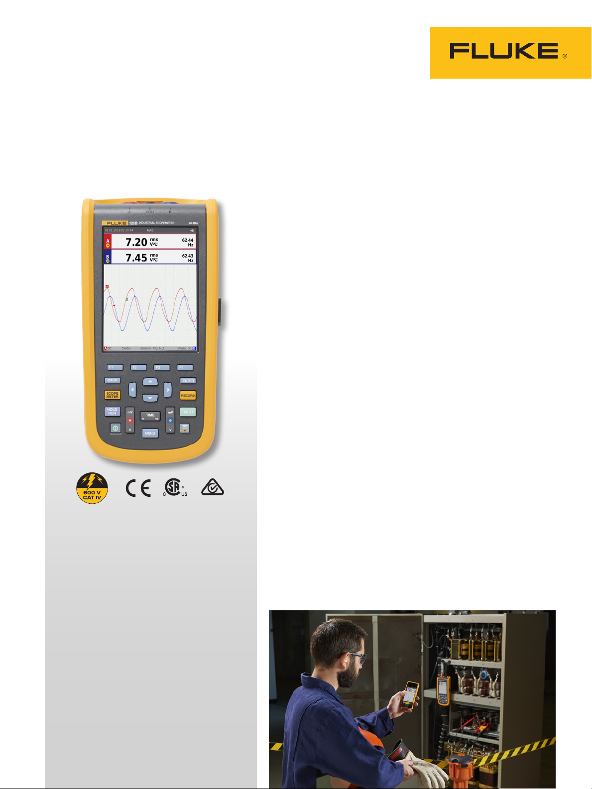
The compact ScopeMeter® 120B Series, is the rugged oscilloscope
solution for industrial electrical and electro-mechanical equipment troubleshooting and maintenance applications. It’s a truly
integrated test tool, with oscilloscope, multimeter and high-speed
recorder in one easy-to-use instrument. The ScopeMeter 120B
Series also integrates with Fluke Connect® mobile app and
FlukeView® for ScopeMeter software to enable further collaboration, data analysis and archiving of critical test information.
The 120B Series Industrial ScopeMeter Test Tools include innovative functions designed to help technicians troubleshoot faster and
get the answers they need to keep their systems up and running.
Display waveforms with Connect and View™ trigger and setup
technology and automatically view related numerical measurements using Fluke IntellaSet™ technology, all without making
manual measurement adjustments. With Recorder Event Detect
capabilities, elusive intermittent events are captured and logged
for easy viewing and analysis.
KEY MEASUREMENTS
Voltage, current and power waveforms
with numerical values including harmonics,
resistance, diode, continuity and
capacitance measurements.
AUTOMATICALLY CAPTURE, VIEW AND
ANALYZE COMPLEX WAVEFORMS
Fluke Connect and View™ triggering
automatically displays waveforms without
having to adjust amplitude, timebase and
trigger settings, while Intellaset™ technology
analyzes the signal and automatically
displays critical numerical readings, making
troubleshooting faster than ever.
FLUKE CONNECT ® CO M PAT I BLE *
View data locally on the instrument,
or via Fluke Connect mobile app.
*Not al l models are available in all countries.
Check w ith your local Fluke representative.
• Dual-input digital oscilloscope and multimeter
• 40 MHz or 20 MHz oscilloscope bandwidth
• Two 5,000-count true-rms digital multimeters
• Connect-and-View™ trigger simplicity for hands-off operation
• IntellaSet™ technology automatically and intelligently adjusts
numerical readout based on the measured signal
• Dual-input waveform and meter reading recorder for
trending data over extended periods
• Recorder Event Detect captures elusive intermittent signals on
repetitive waveforms up to 4 kHz
Page 2
*Not al l models are available in all countries. Check with
your local Fluke representative.
• Shielded test leads for oscilloscope, resistance and
continuity measurements
• Resistance, continuity, diode and capacitance meter
measurements
• Power measurements (W, VA, VAR, PF, DPF, Hz)
• Voltage, current and power harmonics
• Check Industrial networks with BusHealth physical layer tests
against defined reference levels
• Save or recall data and instrument setups
• Store instrument setups defined by a test sequence for routine
maintenance or most often used test procedures.
• External optically isolated USB interface to transfer, archive
and analyze scope or meter data
• Optional WiFi adapter connected to internal USB port to
wirelessly transfer information to the PC, laptop or
Fluke Connect® mobile app*
• FlukeView
®
ScopeMeter® Software for Windows
®
• Rugged design to withstand 3g Vibration, 30g shock, and
rated IP51 according to EN/IEC60529
• Highest safety rating in the industry: safety rated for
CAT IV 600V
• Li-Ion rechargeable battery, seven-hours operation (with
four-hour charge time)
Fluke Connect-and-View™ triggering
with Auto Reading function using Fluke
IntellaSet™ technology gives you quick
access to the data you need.
Connect-and-View™
triggering for an instant,
stable display
Oscilloscope users know how
difficult triggering can be.
Using the wrong settings can
lead to unstable waveform
captures, and sometimes the
wrong measurement data.
Fluke’s unique Connect-andView™ triggering technology
recognizes signal patterns, and
automatically sets up the correct
triggering to provide a stable,
reliable and repeatable display.
Connect-and-View™ triggering
is designed to work with virtually any signal, including motor
drives and control signals—
without adjusting parameters,
or even touching a button.
Signal changes are instantly
recognized and settings are
automatically adjusted, providing a stable display even when
measuring multiple test points
in quick succession.
IntellaSet™/AutoReading
The Auto Readings function
with Fluke IntellaSet™ technology uses proprietary algorithms
to intelligently analyze the
measured waveform and automatically displays the most
appropriate numerical measurements on screen, so you can get
the data you need easier than
ever before. As an example,
when the measured waveform is a line voltage signal,
the Vrms and Hz readings
are automatically displayed,
whereas if the measured
waveform is a square wave, the
Vpeak-peak and Hz readings
are automatically displayed.
Using IntellaSet™ technology
in conjunction with Connectand-View™ automatic triggering
you can be sure you’re seeing
not only the correct waveform, but the appropriate
numerical reading as well. All
without touching a button.
2 Fluke Corporation Fluke 120B Series Industrial ScopeMeter® Hand-Held Oscilloscopes
Page 3
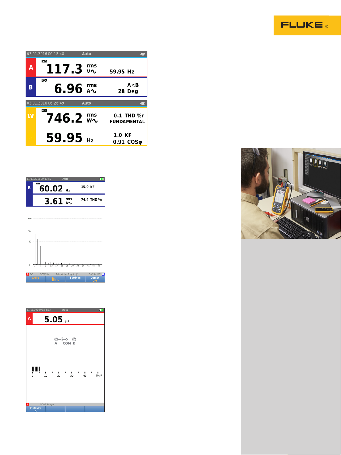
Easily obtai n key power characteristics to validate a system
power.
Harmonics measurements
Harmonics are periodic distortions of voltage,
current, or power sine waves. Harmonics in
power distribution systems are often caused
by non-linear loads such as switched mode
dc power supplies and adjustable speed motor
drives. Harmonics can cause transformers,
conductors, and motors to overheat. In the
Harmonics function, the Test Tool measures
harmonics to the 51st. Related data such as dc
components, THD (Total Harmonic Distortion),
and K factor are measured to provide a complete insight in to the electrical state of health
of your loads.
Harmonic spectrum overview with cursors
to measure the distortion as a percentage
of the fundamental.
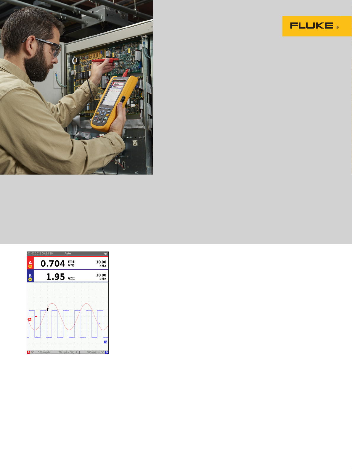
One test lead to measure multiple
electrical parameters
High frequency waveform, meter, capacitance and
resistance measurements as well as continuity
checks are all covered by single set of shielded
test leads. No time is wasted finding or swapping
leads.
Industrial equipment needs a reliable power supply to
operate properly, use the dual input to obtain key power
measurements.
For single phase or 3-phase balanced systems, the dual inputs
of the Industrial ScopeMeter® 120B Series can measure ac+dc
rms voltage on channel A and ac+dc rms current on channel
B. The Fluke 125B can then calculate; frequency, phase angle,
active power (kW), reactive power (VA or var), power factor (PF)
or displacement power factor (DPF) and can also calculate the
power values for a 3-phase system where all phases have equal
voltage and currents. This applies to both balanced system and
resistive loads.
FlukeView® ScopeMeter®
Software for Windows
®
Get more out of your ScopeMeter
120B with FlukeView®Software:
• Store instrument’s screen
copies on the PC, in color
• Copy screen images into your
reports and documentation
• Capture and store waveform
data from your ScopeMeter
on your PC
• Create and archive waveform references for easy
comparison
• Copy waveform data into
your spreadsheet for detailed
analysis
• Use cursors for parameter
measurement
• Add user text to instrument
setups and send them to the
instrument for operator reference and instructions
A single test tool measures volts, ohms,
amps or capacitance, in addition to
displaying waveforms.
3 Fluke Corporation Fluke 120B Series Industrial ScopeMeter® Hand-Held Oscilloscopes
Page 4
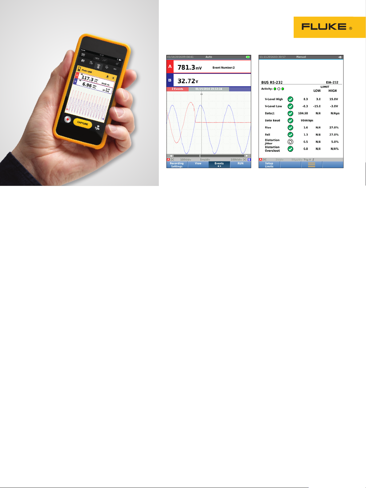
Quickly step through recorded events
to identify and troubleshoot intermittent
faults.
Quickly understand industrial field bus
signal physical layer analog characteristics.
Fluke Connect mobile app
compatibility
Automated industrial machinery
is harder than ever to trouble
shoot. It’s not enough to just
know where you have to test,
you also have to know what to
look for—and that can be hard
without baseline measurement
data or access to subject matter
experts. The Fluke Connect®
Assets wireless system of
software and wireless test tools
enables technicians to reduce
maintenance costs and increase
uptime with accurate equipment records and maintenance
data that is easy to interpret,
and share. Compare and
contrast test point measurement data and trends so you
can better understand signal
characteristics and changes
over time. And, by storing
maintenance data on the Fluke
Cloud™ you can enable team
members to access it from
wherever and whenever they
need to so you can get advice
or approvals in the field and
get your systems up and running faster than ever before.
Use the comprehensive
recorder modes to help find
intermittent faults with ease
The toughest faults to find are
those that happen only once
in a while—intermittent events.
They can be caused by bad
connections, dust, dirt, corrosion or simply broken wiring
or connectors. Other factors,
like line outages and sags or
the starting and stopping of
a motor, can also cause intermittent events resulting in
equipment shutdowns. When
these events happen, you may
not be around to see it. But,
your Fluke ScopeMeter® Test
Tool will. You can either plot the
minimum and maximum peak
measurement values or record
the waveform trace. And, with
expandable micro SD memory,
recording sessions can be done
for up to 14 days. This recorder
is even more powerful with
the addition of Recorder Event
Detect, which makes detecting and logging intermittent
faults easier than ever. Just set a
threshold on a meter reading or
scope trace and deviations are
tagged as unique events. You no
longer need to search through
masses of data to pinpoint faults,
and can quickly step from one
tagged event to the next, while
still having access to the full
data set.
Industrial Bus Health Test
verifies electrical signal
quality on industrial buses
Bus Health Test analyzes the
electrical signals on the industrial bus or network and gives
a clear “Good”, “Weak” or “Bad”
indication mark for each of the
relevant parameters, presented
next to the actual measurement
value. Measured values are
compared to standard values
based on the selected bus types
(CAN-bus, Profi-bus, Foundation
Field, RS-232 and many more),
or, unique reference values
can be set if different tolerances are required. The Fluke
125B can validate the quality
of the electrical signals as soon
as they are passed along the
network, without looking at the
data content. Additionally, the
125B checks the signal levels
and speed, transition times and
distortion, and compares these
to the appropriate standards
to help you find errors such as
improper cable connections, bad
contacts, incorrect grounding or
improper terminators.
4 Fluke Corporation Fluke 120B Series Industrial ScopeMeter® Hand-Held Oscilloscopes
Page 5

Specifications
Oscilloscope mode
Vertical
Frequency response - dc coupled without probes and test leads (with BB120) 123B: dc to 20 MHz (-3 dB)
with STL120-IV 1:1 shielded test leads DC to 12.5 MHz (-3 dB) / dc to 20 MHz (-6 dB)
with V P41 10:1 Probe 123B: dc to 20MHz (-3 dB)
Frequency response - ac coupled
(lf roll off)
Rise time, excluding probes,
test leads
Input impedance without probes and test leads 1 MΩ//20 pF
Sensitivity 5 mV to 200 V/div
Analog bandwidth limiter 10 k H z
Display modes A, -A, B, -B
Max. input voltage A and B direct, with test leads, or with VP41 Probe 600 Vrms CAT IV, 750 Vrms maximum voltage.
Max. floating voltage, from any
terminal to ground
Horizontal
Scope modes Normal, Single, Roll
Ranges (Normal)
Sampling rate (for both channels
simultaneously)
Trigger
Screen update Free run, on trigger
Source A, B
Sensitivity A and B @ DC to 5 MHz 0.5 divisions or 5 mV
Slope Positive, negative
Advanced scope functions
Display modes Normal Captures up to 25 ns glitches and displays
Auto set (Connect-and-View™) Continuous fully automatic adjustments of amplitude, time base, trigger levels, trigger gap, and
without probes and test leads <10 Hz (-3 dB)
with STL120-IV 1:1 shielded test leads <10 Hz (-3 dB)
with V P41 10:1 Probe <10 Hz (-3 dB)
123B <17.5 ns
124B and 125B <8.75 ns
wit h BB120 1 MΩ//24 pF
with STL120-IV 1:1 shielded test leads 1 MΩ//230 pF
with V P41 10:1 Probe 5 MΩ//15.5 pF
wit h BB120 600 Vrms
600 Vrms CAT IV, 750 Vrms up to 400Hz
Equivalent sampling 123B: 20 ns to 500 ns/div,
Real time sampling 1 μs to 5 s/div
Single (real time) 1 μs to 5 s/div
Roll (real time) 1s to 60 s/div
Equivalent sampling (repetitive signals) up to 4 GS/s
Real time sampling 1 μs to 60 s/div 40 MS/s
@ 40 MHz 123B: 4 divisions
@ 60 MHz 123B: N/A
Smooth Suppresses noise from a waveform.
Glitch off Does not capture glitches between samples
Envelope Records and displays the minimum and
hold-off. Manual override by user adjustment of amplitude, time base, or trigger level.
124B and 125B: dc to 40 MHz (-3 dB)
124B and 125B: dc to 40 MHz (-3 dB)
124B and 125B: 10 ns to 500 ns/div
124B and 125B: 1.5 divisions
124B and 125B: 4 divisions
analog-like persistence waveform.
maximum of waveforms over time.
5 Fluke Corporation Fluke 120B Series Industrial ScopeMeter® Hand-Held Oscilloscopes
Page 6

Dual input meter
The accuracy of all measurements is within ± (% of reading + number of counts) from 18 °C to 28 °C.
Add 0.1x (specific accuracy) for each °C below 18 °C or above 28 °C. For voltage measurements with 10:1 probe, add probe
uncertainty +1 %. More than one waveform period must be visible on the screen.
Input A and input B
DC voltage (VDC)
Ranges 500 mV, 5 V, 50 V, 500 V, 750 V
Accuracy ± (0.5 % +5 counts)
Common mode rejection (CMRR) >100 dB @ dc, >60 dB @ 50, 60, or 400 Hz
Full scale reading 5000 counts
True-rms voltages (V ac and V ac+dc)
Ranges 500 mV, 5 V, 50 V, 500 V, 750 V
Accuracy for 5 % to 100 % of
range (DC coupled)
Accuracy for 5 % to 100 % of
DC to 60 Hz (V ac+dc) ± (1 % +10 counts)
1 Hz to 60 Hz (V ac) ± (1 % +10 counts)
60 Hz to 20 kHz ± (2.5 % +15 counts)
range (AC or dc coupled)
DC rejection (only VAC) >50 d B
Common mode rejection (CMRR) >100 dB @ dc
>60 dB @ 50, 60, or 400 Hz
Full scale reading 5000 counts, reading is independent of any signal crest factor.
Peak
Modes Max peak, Min peak, or pk-to-pk
Ranges 500 mV, 5 V, 50 V, 500 V, 2200 V
Accuracy Accuracy Max peak or Min peak 5 % of full scale
Accuracy Peak-to-Peak 10 % of full scale
Full scale reading 500 counts
Frequency (Hz)
Ranges 123B: 1 Hz, 10 Hz, 100 Hz, 1 kHz, 10 kHz, 100 kHz,1 MHz, 10 MHz, and 50 MHz
124B and 125B: 1 Hz, 10 Hz, 100 Hz, 1 kHz, 10 kHz, 100 kHz, 1 MHz, 10 MHz, and 70 MHz
Frequency range 15 Hz (1 Hz) to 50 MHz in continuous autoset
Accuracy @1 Hz to 1 MHz ± (0.5 % +2 counts)
Full scale reading 10 000 counts
RPM
Max reading 50.00 kRPM
Accuracy ± (0.5 % +2 counts)
Duty cycle (PULSE)
Range 2 % to 98 %
Frequency range 15 Hz (1 Hz) to 30 MHz in continuous autoset
Pulse width (PULSE)
Frequency range 15 Hz (1 Hz) to 30 MHz in continuous autoset
Full scale reading 1000 counts
Amperes (AMP)
With current clamp Ranges same as V dc, V ac, V ac+dc, or PEAK
Scale factors 0.1 mV/A, 1 mV/A, 10 mV/A, 100 mV/A, 400 mV/A,
1 V/A, 10 mV/mA
Accuracy same as V dc, V ac, V ac+dc, or PEAK
(add current clamp uncertainty)
6 Fluke Corporation Fluke 120B Series Industrial ScopeMeter® Hand-Held Oscilloscopes
Page 7

Temperature (TEMP) with optional temperature probe
Range 200 °C/div (200 °F/div)
Scale factor 1 mV/°C and 1 mV/°F
Accuracy as V dc (add temp. probe uncertainty)
Decibel (dB)
0 dBV 1 V
0 dBm (600 Ω /50 Ω) 1 mW referenced to 600 Ω or 50 Ω
dB on V dc, V ac, or Vac+dc
Full scale reading 1000 counts
Crest factor (CREST)
Range 1 to 10
Full scale reading 90 Counts
Phase
Modes A to B, B to A
Range 0 to 359 degrees
Resolution 1 degree
Power (125B only)
Configurations 1 phase / 3 phase 3 conductor balanced loads (3 phase: fundamental component only, AUTOSET
mode only)
Power factor (PF) Ratio between watts and VA range - 0.00 to 1.00
Watt RMS reading of multiplying corresponding samples of input A (volts) and input B (amperes)
Full scale reading 999 counts
VA Vrms x Arms
Full scale reading 999 counts
VA reactive (var) √((VA)2-W2)
Full scale reading 999 counts
Vpwm
Purpose to measure on pulse width modulated signals, like motor drive inverter outputs
Principle readings show the effective voltage based on the average value of samples over a whole number of
periods of the fundamental frequency
Accuracy as Vrms for sinewave signals
Input A to common
Ohm (Ω)
Ranges 123B and 124B 500 Ω , 5 kΩ, 50 kΩ, 500 kΩ, 5 MΩ, 30 MΩ
125B 50 Ω, 500 Ω , 5 kΩ, 50 kΩ, 500 kΩ, 5 MΩ, 30 MΩ
Accuracy ± (0.6 % + 5 counts) 50 Ω ±(2 % + 20 counts)
Full scale reading 50 Ω to 5 MΩ - 5000 counts, 30 MΩ - 3000 counts
Measurement current 0.5 mA to 50 nA, decreases with increasing ranges
Open circuit voltage <4 V
Continuity (Cont)
Beep <(30 Ω ± 5 Ω) in 50 Ω range
Measurement current 0.5 mA
Detection of shorts of ≥1 ms
Diode
Measurement voltage @0.5 mA >2. 8 V
@open circuit <4 V
Measurement current 0.5 mA
Polarity + on input A, - on COM
7 Fluke Corporation Fluke 120B Series Industrial ScopeMeter® Hand-Held Oscilloscopes
Page 8

Capacitance (CAP)
Ranges 50 nF, 500 nF, 5 μF, 50 μF, 500 μF
Full scale reading 5000 counts
Measurement current 500 nA to 0.5 mA, increases with increasing ranges
Advanced meter functions
Zero Set Set actual value to reference
AutoHold (on A) Captures and freezes a stable measurement result. Beeps when stable. AutoHold works on the main
meter reading, with thresholds of 1 Vpp for AC signals and 100 mV for DC signals.
Fixed decimal point Activated by using attenuation keys.
Cursor Readout (124B and 125B)
Sources A, B
Single vertical line Average, min and max readout
Average, min, max and time from start of readout (in ROLL mode; instrument in HOLD)
Min, max and time from start of readout (in RECORDER mode; instrument in HOLD)
Harmonics values in POWER QUALITY mode.
Dual vertical lines Peak-peak, time distance and reciprocal time distance readout
Average, min, max and time distance readout (in ROLL mode; instrument in HOLD)
Dual horizontal lines High, low and peak-peak readout
Rise or fall time Transition time, 0 %-level and 100 %-level readout (manual or auto leveling; auto leveling only
possible in single channel mode)
Accuracy As oscilloscope accuracy
Recorder
The recorder captures meter readings in Meter Recorder mode or continuously captures waveform samples in Scope Recorder mode. The
information is stored on internal memory or on optional SD card (with the 125B or 124B).
The results are displayed as Chart recorder display that plots a graph of min and max values of Meter measurements over time or as a
waveform recorder display that plots all the captured samples.
Meter readings
Measurement Speed Maximum 2 measurements/s
Record Size (min, max, average) 2 M readings for 1 channel
Recorded Time Span 2 weeks
Maximum number of events 1024
Waveform record
Maximum sample rate 400 K sample/s
Size Internal memory 400 M samples Recorded Time
Span internal memory 15 minutes at 500 μs/div 11 hours at 20 ms/div
Record Size SD card 1.5 G samples
Recorded Time Span SD card 11 hours at 500 μs/div 14 days at 20 ms/div
Maximum number of events 64
8 Fluke Corporation Fluke 120B Series Industrial ScopeMeter® Hand-Held Oscilloscopes
Page 9

Power Quality (125B only)
Readings Watt, VA, var, PF, DPF, Hz
Watt, VA, var ranges (auto) 250 W to 250 MW, 625 MW, 1.56 GW
when selected: total (%r) ± (2 % + 6 counts)
when selected: fundamental (%f) ± (4 % + 4 counts)
DPF 0.00 to 1.00
PF 0.00 to 1.00, ± 0.04
Frequency range 10.0 Hz to 15.0 kHz 40.0 Hz to 70.0 Hz
Number of Harmonics DC to 51
Readings / Cursor readings
(fundamental 40 Hz to 70 Hz)
V rms / A rms /Watt each harmonic from fundamental maybe selected
for individual readings
Includes frequency of fundamental, phase Angle and K-factor (in Amp and Watt)
Bus health tester (Fluke 125B only)
Type Subtype Protocol
AS-i NEN-EN50295
CAN I SO -1189 8
Interbus S RS-422 EIA-422
Modbus RS-232 RS-232/EI A-232
RS-485 RS-485/EIA-485
Foundation Fieldbus H1 61158 type 1, 31.25 kBit
Profibus DP EIA-485
PA 61158 type 1
RS-232 EI A-232
RS-485 EIA-485
Miscellaneous
Display Type 5.7-inch color active matrix TFT
Resolution 640 x 480 pixels
Waveform Display Vertical 10 div of 40 pixels
Horizontal 12 div of 40 pixels
Power External via Power Adapter BC430
Input voltage 10 V DC to 21 V DC
Power consumption 5 W typical
Input connector 5 mm jack
Internal via Battery Pack BP290
Battery power Rechargeable Li-Ion 10.8 V
Operating time 7 hours with 50 % backlight brightness
Charging time 4 hours with test tool off,
7 hours with test tool on
Allowable ambient temp 0 to 40 °C (32 to 104 °F) during charging
Memory Internal memory can store 20 data sets
(screen waveform and setup)
Micro SD card slot with optional SD card
(max size of 32 GB)
Mechanical Size 259 mm x 132 mm x 55 mm
(10.2 in x5.2 in x 2.15 in)
Weight 1.4 kg (3.2 lb) including battery pack
9 Fluke Corporation Fluke 120B Series Industrial ScopeMeter® Hand-Held Oscilloscopes
Page 10

Interface Optically isolated Transfer screen copies (bitmaps), settings and
USB to PC/laptop OC4USB optically isolated USB adapter/cable,
Optional WiFi adapter Fast transfer of screen copies (bitmaps), settings
Environmental
Environmental MIL-PRF-28800F, Class 2
Temperature Battery Operation 0 to 40 °C (32 to 104 °F)
Power Adapter Operation 0 to 50 °C (32 to 122 °F)
Storage -20 to 60 °C (-4 to 140 °F)
Humidity (Operating) @ 0 to 10 °C (32 to 50 °F) noncondensing
@ 10 to 30 °C (50 to 86 °F) 95 %
@ 30 to 40 °C (86 to 104 °F) 75 %
@ 40 to 50 °C (104 to 122 °F) 45 %
Storage @ -20 to 60 °C (-4 to 140 °F) noncondensing
Altitude Operating at 3 km (10 000 feet) CAT III 600 V
Operating at 2 km (6 600 feet) CAT IV 600 V
Storage 12 km (40 000 feet)
EMC electromagnetic
compatibility
Wireless radio with adapter Frequency range 2412 MHz to 2462 MHz
Enclosure protection IP51, ref: EN/IEC60529
Safety General IEC 61010-1: Pollution Degree 2
Max. input voltage input A and B Direct on input or with leads 600 Vrms CAT IV for derating
International IEC 61326-1: Industrial, CISPR 11:
Korea (KCC) Class A Equipment (Industrial Broadcasting &
USA (FCC) 47 CFR 15 subpart B. This product is considered
Output power <10 0 mW
Measurement IEC 61010-2-033: CAT IV 600 V/CAT III 750 V
With Banana-to BNC Adapter BB120 600 Vrms for derating
Max. floating voltage from any terminal to ground 600 Vrms CAT IV, 750 Vrms up to 400 Hz
data
(optional), using FlukeView® software for
Windows®.
and data to PC/laptop, tablet, smartphone, etc.
A USB port is provided for attaching the WiFi
dongle. Do not use the USB port with a cable for
safety reasons.
Group 1, Class A
Communication Equipment)
an exempt device per clause 15.103.
Fluke 123B Fluk e 124B Fl uke 125B
Functions
Full function dual input scope and meter
Oscilloscope bandwidth MHz 20 40 40
Meter and Scope Recorder
Scope cursor measurements
Power and harmonics measurements
Bus health
Included accessories
10:1 voltage probe
i400S AC Current Clamp
10 Fluke Corporation Fluke 120B Series Industrial ScopeMeter® Hand-Held Oscilloscopes
· · ·
· · ·
· ·
· ·
·
·
·
Page 11

Ordering information
1:23 PM
100%
A
VAC rms
VAC rms
B
Fluke-123B Industrial ScopeMeter® Hand Held
Oscilloscope (20 MHz)
Fluke-123B/S Industrial ScopeMeter® Hand Held
Oscilloscope (20 MHz)*
Fluke-124B Industrial ScopeMeter® Hand Held
Oscilloscope (40 MHz)
Fluke-124B/S Industrial ScopeMeter® Hand Held
Oscilloscope (40MHz)*
Fluke-125B Industrial ScopeMeter® Hand Held
Oscilloscope (40MHz)
Fluke-125B/S Industrial ScopeMeter® Hand Held
Oscilloscope (40MHz)*
Includes: Li-Ion battery pack, charger/power
adapter, 2 shielded test leads with ground leads,
black test lead, red and blue hook clips, banana
to BNC adapter, and WiFi USB adapter**
*Fluke 120B/S versions also include soft carry case,
Flu keView™ for Windows® software, magnetic hanger,
and screen protector.
**WiFi USB adapter NOT available in all countries. Check
with your local Fluke representative.
ST L120 -I V Shielded Test Lead Set 600 V CAT IV
HC120-II Set of 2 hook clips
BB120 -II Set of 2 banana to BNC adapter
VPS41 Voltage probe set 40MHz 600 V CAT IV
C120B Soft Carrying Case For 120B Series
SP120B Screen Protector For 120B Series
SCC120B Accessory Kit 120B Series
OC4USB Fluke OC4USB USB Interface Cable
Fluke 80i 110s Fluke 80i-110s AC/DC Current
Clamp
Fluke i1000s Fluke i1000s AC Current Probe
Fluke i1010 Fluke i1010 AC/DC Current Clamp
Fluke i200s Fluke i200s AC Current Clamp
Fluke-i3000s Fluke i3000s AC Current Clamp
Fluke i3000s Flex 24 Fluke i3000s Flex-24 AC
Current Clamp, 610 mm (24 in.)
Fluke i3000s Flex 36 Fluke i3000s Flex-36 AC
Current Clamp, 915 mm (36 in.)
Fluke i30s Fluke i30s AC/DC Current Clamp
Fluke-i 310s Fluke i310s Current Probe
Fluke i400s Fluke i400s AC Current Clamp
Fluke i410 Fluke i410 AC/DC Current Clamp
Fluke i5S Fluke i5S AC Current Clamp
Fluke 125B
1.268
99.8
Set up and sustain preventive maintenance practices with
ease to help you oversee your complex world with the Fluke
Connect® system of software and over 40 wireless test tools.
• Maximize uptime and make confident maintenance decisions with data
you can trust and trace.
• Save measurements to the Fluke Cloud™ and associate with an asset so
your team can consult baseline, historical and current measurements
from one location.
• Collaborate with ease by sharing your measurement data with team
members with ShareLive™ video calls and emails.
• Wireless one-step measurement transfer with AutoRecord™ measurements eliminates transcription errors, clipboards, notebooks and multiple
spreadsheets.
• Generate reports with multiple measurement types to provide status or
next step recommendations.
Find out more and take a free trial at: flukeconnect.com
Google and Android store images
WiFi or cellular service is required to share data. Smart phone, wireless
service and data plan not included with purchase. First 5 GB of storage is
free. Phone support details can be viewed at fluke.com/phones.
Download the app at:
Smartphone wireless service and data
plan not included with purchase.
Fluke Connect is not available in all countries.
Fluke. Keeping your world
up and running.
Fluke Corporation
PO Box 9090, Everett, WA 98206 U.S.A.
Fluke Europe B.V.
PO Box 1186, 5602 BD
Eindhoven, The Netherlands
Modification of this document is not permitted
without written permission from Fluke Corporation.
®
For more information call:
In the U.S.A. (800) 443-5853 or
Fax (425) 446-5116
In Europe/M-East/Africa +31 (0) 40 2675
200 or
Fax +31 (0) 40 2675 222
In Canada (800)-36-FLUKE or
Fax (905) 890-6866
From other countries +1 (425) 446-5500 or
Fax +1 (425) 446-5116
Web access: http://www.fluke.com
©2016 Fluke Corporation.
Specifications subject to change without notice.
Printed in U.S.A. 1/2016 6006986b-en
11 Fluke Corporation Fluke 120B Series Industrial ScopeMeter® Hand-Held Oscilloscopes
 Loading...