


FLUENT AUDIO FA WT900 BP, FA WT900 HH User Manual
H
L
z
H
Shenzhen Alcors Technology Co.,Ltd
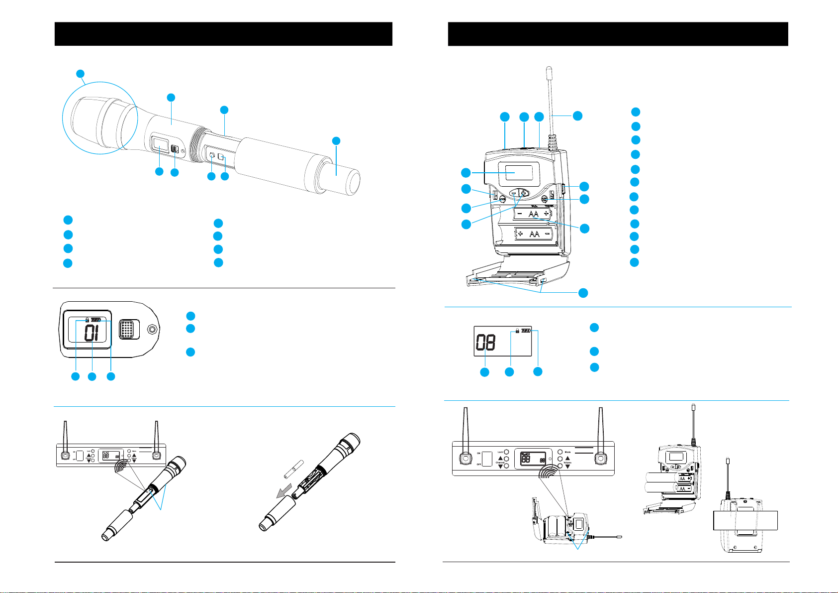
Hand Held Mic Transmitter
1
5
1
Microphone head .
2
Body o f radio micro hpne
3
Bettery compartment (2AA)
4
Antenna position.
1
Screen instructions
3
2
FA-WT900-HH
2
3
6
1
2
3
8
7
5
Disply ,backlit in green.
6
ON/OFF switch.
7
SET button.
8
IR sensor.
Lock indication.
Channel display.Infrared counterpart ,
Don't need to adjust.
Battery indicator.
Belt Pack Transmitter
1
4
12
11
10
9
3
2
FA-WT900-BP
4
5
6
7
8
1
Channel display.Infrared counterpart ,
1
Mic in ,3 .5mm jack .
2
ON/O FF s witch.
3
Charging LED.
4
Ante nn a .
5
Charging port,(via mini usb).
6
SET button.
7
Battery compartment.
8
Battery compartment latches.
9
“+/-” buttons.
10
Lock b ut ton.
11
IR sensor.
12
Disply ,backlit in green.
(This b utt on is u sel es s)
(This b utt on is u sel es s)
Don't need to adjust.
CCH
3
2
1
Screen instructions
2
Lock indication.
3
Battery indicator.
Digital Wir eless
Microphone
VOL
ANT-A
CH
ANT-B
ANT-A
VVOOL
CCH
MMHHz
Digital Wireless
Microphone
ANT-B
Two AA batteries
Pres s this button and
turn o n
Two AA batt er ies
Press this button and turn on
H
L
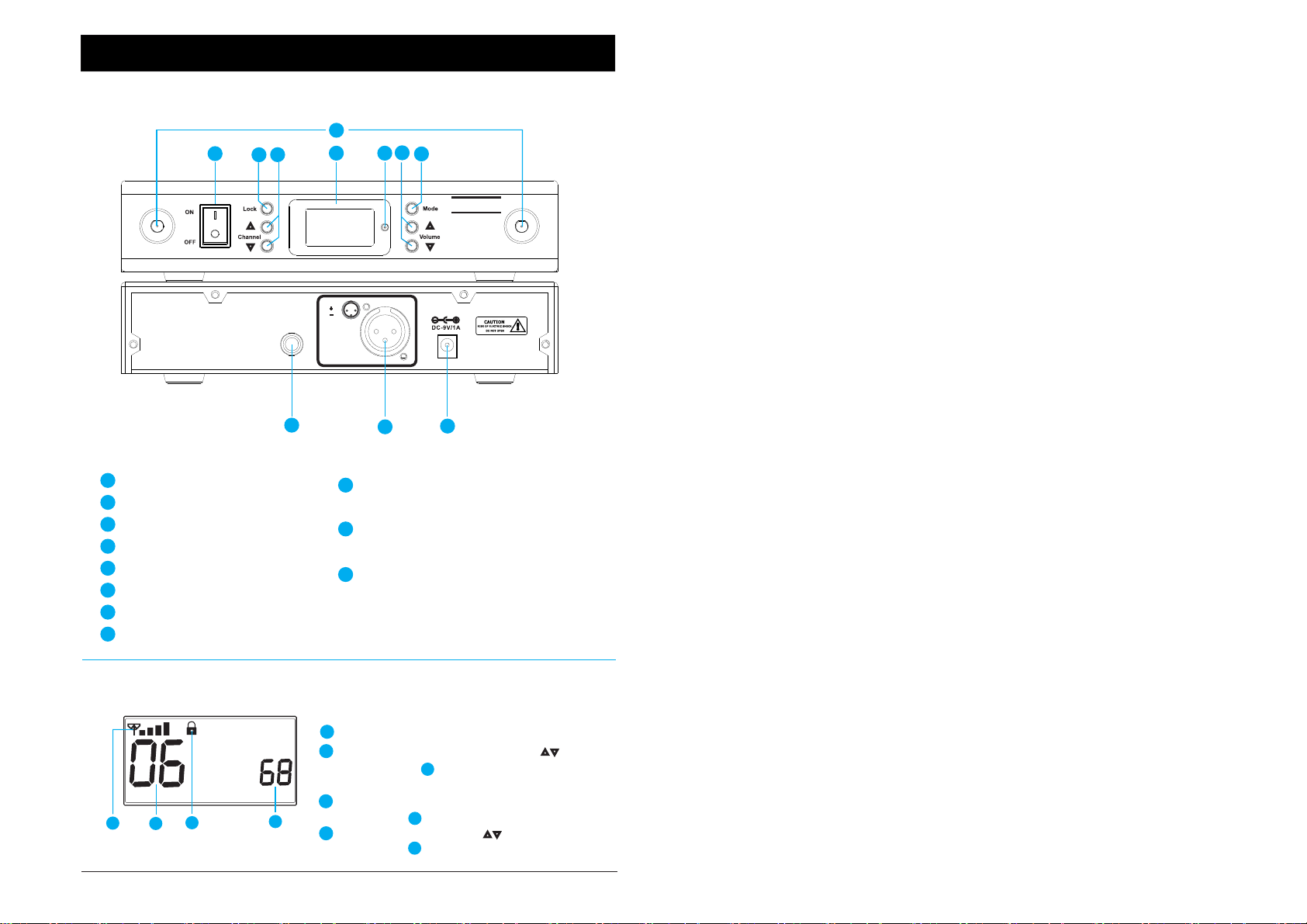
Receiver insturctions
1
A
ANT-A
Digital Wireless Microphone
B
1
ON/OFF switch.
2
Lock button.
3
Channel +/- button.
4
Disply ,ba ck li t in o ra ng e.
IR sensor.
5
6
Volume +/- bu tt on .
7
Mode button.
8
Antenna
A&B.
8
3
2
4
6
5
7
Changes or modifications not expressly approved by the party
responsible for compliance could void the user's authority to operate the
Digi tal Wir eless
Microphone
equipment.
ANT-B
Note: This equipment has been tested and found to comply with the
limits for a Class B digital device, pursuant to part 15 of the FCC Rules.
Balanced
Output
1.GND
2.
3.
Balanced
Output
21
3
These limits are designed to provide reasonable protection against
harmful interference in a residential installation. This equipment
generates, uses and can radiate radio frequency energy and, if not
installed and used in accordance with the instructions, may cause
harmful interference to radio communications. However, there is no
9
10
11
guarantee that interference will not occur in a particular installation. If
this equipment does cause harmful interference to radio or television
reception, which can be determined by turning the equipment off and
9
Audio output(AF OUT BAL),
6.3mm jack ,balanced.
10
Audio output (AF OUT BAL),
XLR socket,balanced.
11
DC IN (3.5mm).
on, the user is encouraged to try to correct the interference by one or
more of the following measures:
—Reorient or relocate the receiving antenna.
—Increase the separation between the equipment and receiver.
—Connect the equipment into an outlet on a circuit different from that
to which the receiver is connected.
—Consult the dealer or an experienced radio/TV technician for help.
CCH
1
2
Screen instructions
1
VVOOL
3
4
Received signal strength indicator.
2
Channel display,unlock press
3
Channel.
3
Lock indication,long press LOCK
button.
4
Volum e di splay,press Volume
button.
(A- )
2
(A- )
6
(A- )