

Page 1
Warranty, Service & Repair
RoHS
Compliant
To register your product with the manufacturer, go to the Flowline
website for on-line registration. The website address is as follows:
www.flowline.com
On-line Warranty Registration can be found under Contact Us on
the Navigation Bar along the side of the home page.
If for some reason your product must be returned for factory service, contact Flowline Inc. at (562)598-3015 to receive a Material
Return Authorization number (MRA), providing the following
information:
1. Part Number, Serial Number
2. Name and telephone number of someone who can answer
technical questions related to the product and its application.
3. Return Shipping Address
4. Brief Description of the Symptom
5. Brief Description of the Application
Once you have received a Material Return Authorization number,
ship the product prepaid in its original packing to:
Flowline Factory Service
MRA _____
10500 Humbolt Street
Los Alamitos, CA 90720
To avoid delays in processing your repair, write the MRA on the
shipping label. Please include the information about the malfunction with your product. This information enables our service technicians to process your repair order as quickly as possible.
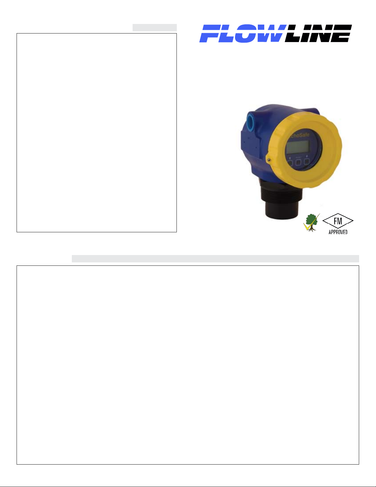
EchoSafe Explosion-Proof
®
Ultrasonic Level Transmitter
Model XP88 / XP89
Owner’s Manual
Version 1.1
© 2007 FLOWLINE Inc.
All rights reserved.
Manual # MN300600 B
WARRANTY
Flowline warrants to the original purchaser of its products that such
products will be free from defects in material and workmanship under
normal use and service for a period which is equal to the shorter of
one year from the date of purchase of such products or two years from
the date of manufacture of such products.
This warranty covers only those components of the products which
are non-moving and not subject to normal wear. Moreover, products
which are modified or altered, and electrical cables which are cut to
length during installation are not covered by this warranty.
Flowline’s obligation under this warranty is solely and exclusively
limited to the repair or replacement, at Flowline’s option, of the
products (or components thereof) which Flowline’s examination
proves to its satisfaction to be defective. FLOWLINE SHALL
HAVE NO OBLIGATION FOR CONSEQUENTIAL DAMAGES
TO PERSONAL OR REAL PROPERTY, OR FOR INJURY TO ANY
PERSON.
This warranty does not apply to products which have been subject
to electrical or chemical damage due to improper use, accident, negligence, abuse or misuse. Abuse shall be assumed when indicated
by electrical damage to relays, reed switches or other components.
The warranty does not apply to products which are damaged during
shipment back to Flowline’s factory or designated service center or
are returned without the original casing on the products. Moreover,
this warranty becomes immediately null and void if anyone other
than service personnel authorized by Flowline attempts to repair the
defective products.
Products which are thought to be defective must be shipped prepaid
and insured to Flowline’s factory or a designated service center (the
identity and address of which will be provided upon request) within
30 days of the discovery of the defect. Such defective products must
be accompanied by proof of the date of purchase.
Flowline further reserves the right to unilaterally waive this warranty
and to dispose of any product returned to Flowline where:
a. There is evidence of a potentially hazardous material present
with product.
b. The product has remained unclaimed at Flowline for longer than
30 days after dutifully requesting disposition of the product.
THERE ARE NO WARRANTIES WHICH EXTEND BEYOND
THE DESCRIPTION ON THE FACE OF THIS WARRANTY.
This warranty and the obligations and liabilities of Flowline under
it are exclusive and instead of, and the original purchaser hereby
waives, all other remedies, warranties, guarantees or liabilities,
express or implied. EXCLUDED FROM THIS WARRANTY IS
THE IMPLIED WARRANTY OF FITNESS OF THE PRODUCTS
FOR A PARTICULAR PURPOSE OR USE AND THE IMPLIED
WARRANTY OF MERCHANT ABILITY OF THE PRODUCTS.
This warranty may not be extended, altered or varied except by a written instrument signed by a duly-authorized officer of Flowline, Inc.
Page 2
SPECIFICATIONS
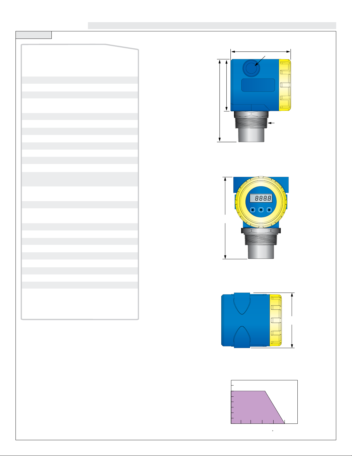
40
30
20
10
00
-40 -20 00 20 40 60 80
Acceptable
Range
Unacceptable
Range
Temperature/Pressure Derating
Operating Pressure (psi)
Temperature ( C)
4.00"
(10.2 cm)
4.44" (11.3 cm)
4.00"
(10.2 cm)
6.06"
15.4 cm
PRELIMINARY XP HOUSING
OVERALL DIMENSIONS
6.06" (15.4 cm)
3.89" (9.9 cm)
2" NPT
UP
DOWN
SELECT
FAST
EchoSafe
™
1/2" NPT
4.00"
(10.2 cm)
6.06"
15.4 cm
PRELIMINARY XP HOUSING
OVERALL DIMENSIONS
UP
DOWN
SELECT
FAST
EchoSafe
™
Range:
Accuracy:
Resolution:
Beam width:
Dead band:
Display type:
Display units:
Memory:
Supply voltage:
Loop resistance:
Signal output:
Signal invert:
Calibration:
Fail-safe:
Process Temp.:
Temp. comp.:
Electronics temp.:
Pressure:
Enclosure rating:
Enclosure mat.:
Window mat.:
Transducer mat.:
Process mount:
Conduit entrance:
Compliance:
Classification:
Approvals:
XP88: 8" to 24.6'
(20 cm to 7.5 m)
XP89: 8" to 32.8'
(20 cm to 10 m)
± 0.2% of max. range
0.079" (2 mm)
3" (7.6 cm) dia.
XP88: 8" (20 cm)
XP99: 8" (20 cm)
LCD, 6-digits
Inch, cm, ft, m, percent
Non-volatile
18-28 VDC (loop)
250Ω max @ 24 VDC
4-20 mA , two-wire
4-20 mA or 20-4 mA
Push button (3-button)
4 mA, 20 mA, 21 mA,
22 mA or hold last
F: -4° to 140°
C: -20° to 60°
Automatic
F: -40° to 160°
C: -40° to 71°
30 psi (2 bar)
NEMA 4
Aluminum
Glass
PVDF
2" NPT
Dual, 1/2" NPT
RoHS
Explosion proof
FM: Class 1, Div 1,
Groups A, B, C, D
Class II/III, Div 1,
Groups E, F, G
Step One
Side View
Front View
Top View
Page 3
SAFETY
Step Two
OVERVIEW
Step Three
About this Manual: PLEASE READ THE ENTIRE MANUAL
PRIOR TO INSTALLING OR USING THIS PRODUCT. This
manual includes information on the XP8_-0 Ultrasonic Level
Transmitter from FLOWLINE. Please refer to the part number
located on the transmitter label to verify the exact model configura-
tion which you have purchased.
User’s Responsibility for Safety: FLOWLINE manufac-
tures a broad range of level sensing technologies. While each of
these sensors is designed to operate in a wide variety of applica-
tions, it is the user’s responsibility to select a sensor model that is
appropriate for the application, install it properly, perform tests of
the installed system, and maintain all components. The failure to do
so could result in property damage or serious injury.
Proper Installation and Handling: Only properly trained
staff should install and/or repair this product. Never overtighten
the transmitter within the fitting. Always check for leaks prior to
system start-up.
Opening The Enclosure: EchoSafe is designed to be
installed in a hazardous areas and, when installed, do not open
the unit while power is applied. Always disconnect the power
source from EchoSafe prior to opening, programming, install-
ing, or removing it. Additionally, ensure that electrical wiring,
fittings and mechanical connections conform to all applicable
electrical codes.
A. Application: The explosion proof ultrasonic transmitter pro-
vides non-contact level detection up to 32.8’ or 10m. The transmitter
is well suited for a wide range of corrosive, waste and slurry type
media, and is broadly selected for atmospheric bulk storage, day tank
and waste sump applications.
B. Part Number: The part and serial numbers are located on the
wrench flat. Check the part number on the product label and confirm
which of the below model configurations you have purchased:
Part Number Range Supply Mount
XP88-0 24.6’ (7.5 m) 18-28 VDC 2” NPT
XP89-0 32.8’ (10 m) 18-28 VDC 2” NPT
Material Compatibility: The XP8_ series enclosure is made
of a Aluminum. The transducer is made of Polyvinylidene Fluoride
(PVDF). Make sure that the model which you have selected is
chemically compatible with the application media and it’s environ-
ment.
Enclosure: While the transmitter housing is liquid-resistant the
XP8_ series is not designed to be operational when immersed. It
should be mounted in such a way that the enclosure and transducer
do not come into contact with the application media under normal
operational conditions.
Make a Fail-Safe System: Design a fail-safe system that
accommodates the possibility of transmitter and/or power failure.
FLOWLINE recommends the use of redundant backup systems
and alarms in addition to the primary system.
Handling Static-Sensitive Circuits/Devices
When handling the transmitter, the technician should follow
these guidelines to reduce any possible electrostatic charge
build-up on the technicians body and the electronic part.
1. Always touch a known good ground source before handling the
part. This should be repeated while handling the part and more
frequently after sitting down from a standing position, sliding
across the seat or walking a distance.
2. Avoid touching electrical terminals of the part unless making connections.
Page 4

PREPARATION
50Khz
012345678910
0%
50%
100%
EchoSafe
™
EchoSafe
™
HEIGHT
(MaxR)
EMPTY
FULL
FILL H
(MinR)
EchoSafe
™
EMPTY
FULL
EchoSafe
™
EchoSafe
™
4 mA
20 mA
20 mA
4 mA
Step Four
MENU ITEMS
Step Five
A. Supply Voltage: The transmitter power supply voltage should
never exceed a maximum of 28 VDC. Flowline controllers and
meters have built-in 24 VDC power supplies for use with the trans-
mitter. Alternative controllers and/or power supplies with a minimum
output of 18 VDC may also be used with the transmitter for calibra-
tion and/or operation.
XP89-0
Reverse Mode
B. Factory Span: All transmit-
ter models are factory calibrated with
4 mA at their maximum range (tank
empty) and 20 mA at their minimum
range (tank full). The 4 and 20 mA
span set points can be reverse cali-
brated on all models.
C. Maximum Applied Range: The Individual or cumulative
effects of agitation or vapor can reduce the overall quality of signal
return and shorten the maximum applied range of the transmitter.
To determine the maximum applied range of the transmitter in your
application, refer to the below de-rating chart.
A. WARM UP: This is the initial power up mode. When this mes-
sage is displayed, the transmitter is going through its power up rou-
tine, and validating the target value. After a short period of time, this
message will disappear and be replaced by a numeric value.
B. FULL: Level has reached the programmed FULL set point.
C. EMPTY: Level has reached the programmed EMPTY set point
D. UNITS: Selectable in inches centimeters, feet, meter or percent.
The factory default is Inches.
E. INCHES: Inch units of measurement.
F. CM: Centimeters units of measurement.
G. FEET: Feet units of measurement.
H. METERS: Meter units of measurement.
I. PERCNT: 0-100% units of measurement. Percent is the calcu-
lated value based on the 4mA and 20mA set points.
J. TANK: Menu through which the
4-20 mA span is adjusted.
K. HEIGHT: The point in inches,
feet, meters, or centimeters from the
transducer face where the output will
be 4 mA (generally the bottom of the
tank). Factory default is the same as
the unit’s maximum range. Example:
XP88 = 295” maximum range which
is also the same 4 mA set point under
factory default.
Maximum Applied Range De-rating Chart
XP88/89-0
Agitation = 1-3 @ 50 kHz
Vapor = 3-5 @ 50 kHz
L. Fill H (Fill Height): The point
in inches, feet, meters or centimeters
from the bottom of the tank to the
high level where the output will be
20 mA (generally the straight wall
distance from the bottom of the tank).
NOTE: The transmitter dead band
is automatically subtracted from the
FILL H. Example: XP88 = 8” dead
band. Therefore the maximum FILL
H is 295” [maximum range] - 8”
[dead band] = 287”.
M. REV mA (Reverse mA): Allows the user to select 20 mA at
the bottom and 4 mA at the top of the tank (20-4 mA). Factory default
is 4 mA (MaxR) at the bottom and 20 mA (MinR) at the top.
N. NORM: Sets EchoSafe so 4 mA is at the bottom of the tank and
20 mA at the top. This is the default settings.
O. REV: Sets EchoSafe so 20 mA is at the bottom of the tank and
4 mA at the top.
Page 5

MENU ITEMS
UP
DOWN
SELECT
FAST
EchoSafe
™
UP
DOWN
SELECT
FAST
EchoSafe
™
Step Six
PROGRAMMING
Step Seven
P. SAFE: The FAIL-SAFE current output of the transmitter if the
acoustic signal is LOST. Selectable at 4 mA, 20 mA, 21 mA, 22 mA
or HOLD. (HOLD is the last 4-20 mA value prior to LOST).
Q. HELP: Allow the user to view the current configuration settings
in EchoSafe.
R. SETUP: Displays the present configuration settings such as
UNITS, HEIGHT, FILL H, SAFE, REV.
S. TEST P: Allows the user to view the test parameters of
SEGMENT CHECK, RANGE, ECHO, POWER, VER.
T. SEGMENT CHECK: Tests all LED segments for operation.
U. RANGE: Displays the current inch, centimeter, feet, meter or
Percent measured value.
V. ECHO: Displays the present acoustic signal strength.
W. POWER: Displays the present acoustic power level
X. VER (VERSION): Displays the transmitter software version.
Y. R ALL: Allows the user to reset the transmitter to its original fac-
tory default settings
EchoSafe is designed to be installed in a hazardous areas, and when installed, do not open the unit while power
is applied. Always disconnect the power source from
EchoSafe prior to opening, programming, installing or
removing it.
A. Introduction: The transmitter has two modes, RUN and
MENU. In the RUN mode, the transmitter is operational and the display will indicate the liquid height in inches, centimeters or percent.
In the MENU mode, the display will indicate the selected mode of
calibration. The transmitter arrives from the factory with its settings
at 4 mA = maximum range and 20 mA = minimum range (defined by
the dead band or minimum measurement distance). The transmitter is
programmed with it’s built-in display and three button keyboard.
B. Entering the Program Mode: Press and hold the
Z. ERROR: Indicates that the new value has NOT been saved in
memory (after depressing the SELECT/FAST or EXIT key).
AA. RUN: When displayed, if the user depresses the SELECT/
FAST key, the transmitter will exit the programming mode and return
to the RUN mode for normal operation.
BB. UP / DOWN: Increases or decreases the SET 20 and SET
4 display values in the programming mode. NOTE: Simultaneously
holding down the SELECT/FAST button while pressing the UP or
DOWN button will increase the speed of the display.
SELECT/FAST button for approximately 5 seconds until the display
changes from a numeric value to MENU, indicating that you have
entered the MENU mode.
Note: When MENU mode is active, the EchoSafe will hold the
last current value. The value will not change until the transmitter is returned to RUN Mode.
Hold for
5 Seconds
After entering the MENU mode, the display will scroll through the
top menu, alternately flashing UNITS, TANK, OUTPUT, HELP and
RUN.
Top Menu
Page 6

PROGRAMMING PROGRAMMING
SELECT
FAST
SELECT
FAST
MENU
EchoSafe
™
EchoSafe
™
HEIGHT
(MaxR)
EMPTY
FULL
FILL H
(MinR)
SELECT
FAST
SELECT
FAST
SELECT
FAST
UP
DOWN
0HQX
SELECT
FAST
SELECT
FAST
SELECT
FAST
UP
DOWN
0HQX
Step Eight
Step Nine
C. Programming UNITS: To change UNITS from INCHES to
CM or PERCENT.
1. Press the SELECT/FAST button and hold it for 5 seconds until
MENU appears.
2. When UNITS appears, press the SELECT/FAST button. The dis-
play will rotate between INCHES, CM,, FT, M, PERCENT and
DISPLAY.
3. Press the SELECT/FAST button when the UNITS you want
(INCHES, CM, FT, M or PERCENT) appear. The display will
then display SAVED.
You have successfully changed the UNITS function.
Note: Percent units can only be selected after the transmitters Height (4 mA) and Fill H (20 mA) set points have
been programmed. Therefore initial programming should
always be done in INCH, CM, FT or M UNITS.
E. Programming HEIGHT: To change HEIGHT 4 mA value.
1. Press the SELECT/FAST button and hold it for 5 seconds until
MENU appears.
2. When TANK appears, press the SELECT/FAST button. The dis-
play will rotate between HEIGHT, FILL H and EXIT.
3. When HEIGHT appears, press the SELECT/FAST button. The
display will show a decimal reading in the selected UNITS.
4. Press the UP/DOWN buttons to increase or decrease this value. This
value is the distance from the transducer face to the bottom of the tank.
NOTE: Simultaneously holding down the SELECT/FAST button
while pressing the UP or DOWN button will increase the speed of the
display.
5. When you have reached the desired value, press SELECT/FAST
to SAVE.
You have successfully programmed the HEIGHT or 4 mA value.
D. Programming Off Tank: If you know the dimensions of
your tank, you may input the 4 mA and 20 mA set points manually.
To do so, review the following:
HEIGHT: The point in inches or centimeters from the transducer
face where the output will be 4 mA (generally the bottom of the
tank). Factory default is the same as the unit’s maximum range.
Example XP88 = 295” maximum range which is also the same 4
mA set point under factory default.
FILL H: The point in inches or centimeters from the bottom of the
tank to the high level where the output will be 20 mA (generally
the straight wall distance from the bottom of the tank). NOTE: The
transmitter dead band is automatically subtracted from the FILL H.
Example: XP88 = 8” dead band. Therefore the maximum FILL H
is 295” [maximum range] - 8” [dead band] = 287”.
F. Programming FILL H: To change FILL H 20 mA value.
1. Press the SELECT/FAST button and hold it for 5 seconds until
MENU appears.
2. When TANK appears, press the SELECT/FAST button. The dis-
play will rotate between HEIGHT, FILL H and EXIT.
3. When FILL H appears, press the SELECT/FAST button. The
display will show a decimal reading in the selected UNITS.
4. Press the UP/DOWN buttons to increase or decrease this value. This
value is the distance from the bottom of the tank to the full point
(typically the straight wall height).
5. When you have reached the desired value, press SELECT/FAST
to SAVE it.
You have successfully programmed the FILL H or 20mA value.
Page 7

EchoSafe
™
4 mA
20 mA
SELECT
FAST
SELECT
FAST
SELECT
FAST
0HQX
(;,7
EchoSafe
™
EchoSafe
™
4 mA
20 mA
20 mA
4 mA
PROGRAMMING
SELECT
FAST
SELECT
FAST
SELECT
FAST
0HQX
Step Ten
PROGRAMMING
Step Eleven
G. Programming SAFE Mode: To change SAFE mode.
1. Press the SELECT/FAST button and hold it for 5 seconds until
MENU appears.
2. When SAFE appears, press the SELECT/FAST button.
3. The display will now rotate through 22mA, 21mA, 20mA,
4mA and HOLD. When you reach the desired setting, press the
SELECT/FAST button to SAVE it..
You have successfully programmed the SAFE mode.
H. Programming REV mA (Optional): In factory default,
the transmitter operates with 4 mA at the maximum range, and 20 mA
at the dead band. Using the menu item REV mA, you can change the
unit to reverse this to 20 mA at the furthest distance and 4 mA at the
closest distance.
Normal mA Mode
(4 mA) set at empty tank
and (20 mA) set at full tank.
Reverse mA Mode
(20 mA) set at empty tank
and (4 mA) set at full tank.
I. Programming REV mA (Mode):
NOTE: You must set HEIGHT and FILL H prior to reversing the 4
and 20 mA. Regardless of which mode you are in (Norm or Rev),
changes to the HEIGHT or FILL H are always with respect to the
original settings programmed.
NOTE: Any changes to the HEIGHT will effect the FILL H
value. The FILL H will stay at the same physical level in the
tank. An increase to the HEIGHT value will result in an equal
increase to the FILL H value. A decrease to the HEIGHT value
will result in an equal decrease to the FILL H value.
Page 8

PROGRAMMING
EchoSafe
EchoSafe
EchoSafe
VACUUM
EchoSafe
EchoSafe
Dead Band
Ventilation
Hole
Operational Range
Highest
Liquid Level
Lowest
Liquid Level
3" Minimum
Diameter
EchoSafe
EchoSafe
EchoSafe
Height
Inner Diameter
EchoSafe
(+)
(-)
24 VDC
12
(FKR6DIH
Ù
Step Twelve
.
Do not install at
angle relative
to the liquid
Do not install
within 3” of
tank side wall
INSTALLATION
Step Thirteen
A. Wiring: A supply voltage of 18 - 28 VDC is used to power the
XP8_ series. The sensor circuit should never exceed a maximum of
28 volts DC. Electrical wiring of the sensor should be performed in
accordance with all applicable national, state, and local codes.
Do not install
with objects
in the beam
Do not install
in applications
with vacuum
Warning
Flowline Ultrasonic transmitters have been optimized for use
in non-metallic fittings. For best performance, avoid the use
of metal fittings.
Install the appropriate installation fitting. Make sure that the
fitting and transmitter threads are not damaged or worn. Hand
tighten the transmitter within the fitting. Perform an installed
leak test under normal process conditions prior to system start
up.
Gasket
A. Fitting Selection: Check the transmitter part
number to determine the required 2” fitting thread
type. The transmitter is commonly installed in tank
adapters, flanges, brackets or stand pipes.
Adapter
1. Adapter: Select a tank adapter fitting with
minimal height so as to ensure that the
installed transducer will not be substantially
elevated into the fitting. Avoid tank adapter
styles with threads and/or pipe stops forward
Flange
of the installed transducer.
2. Flange: Tall flanges with narrow risers
impede the acoustic signal. Select a fit-
Bracket
Riser
diameter geometry. The transmitter may be
elevated up to 12” (30 cm) in a 6” (15 cm)
riser, 8” (20 cm) in a 4” (10 cm) riser and 3”
ting with the right riser height versus inner
(7.6 cm) in a 2” (5 cm) riser.
Opening The Enclosure: EchoSafe is designed to be installed
in a hazardous areas and, when installed, do not open the unit
while power is applied. Always disconnect the power source from
EchoSafe prior to opening, programming, installing, or removing it.
Additionally, ensure that electrical wiring, fittings and mechanical
connections conform to all applicable electrical codes.
Stand Pipe
3. Bracket: The LM50-1001 bracket or equiva-
lent can be used for open tank top installa-
tions against the side wall.
4. Stand Pipe: A stand pipe may be
used to dampen turbulence or separate
surface foam. Select a minimum 3”
pipe for the stand pipe. The pipe length
should run the measurement span. Cut a
45° notch at the bottom of the pipe and
drill a 1/4” pressure equalization hole in
the dead band.
Page 9

SELECT
FAST
SELECT
FAST
SELECT
FAST
0(18
:$,7
(;,7
TROUBLESHOOTING
Transmitter
XP88-0
XP89-0
4 mA Setting
26.4 (7.5m)
32.8 (10m)
20 mA Setting
8 (20 cm)
12 (30 cm)
Factory Set Points
Power
Supply
Power
Supply
2
0 mA
4 mA
mA
456
mA
192021
Black
Red
EchoSafe
EchoSafe
Black
Red
SELECT
FAST
SELECT
FAST
SELECT
FAST
0HQX
81,76
+(,*+7
),//+
6$)(
5(90$
'21(
SELECT
FAST
SELECT
FAST
SELECT
FAST
0(18
:$,7
5$1*(
9(5
Step Fourteen
A. Viewing Programmed VALUES:
1. Press the SELECT/FAST button and hold it for 5 seconds until
MENU appears.
2. When HELP appears, press the SELECT/FAST button. The dis-
play will rotate between SETUP, TEST P and R ALL.
3. When SETUP appears, press the SELECT/FAST button. You will
now begin viewing calibration settings (UNITS, HEIGHT, FILL
H, SAFE, REV mA) that are programmed in the transmitter.
When complete the display will revert back to the HELP menu.
TROUBLESHOOTING
Step Fifteen
C. Factory RESET:
1. Press the SELECT/FAST button and hold it for 5 seconds until
MENU appears.
2. When HELP appears, press the SELECT/FAST button. The display will rotate between SETUP, TEST P and R ALL.
3. When R ALL appears, press the SELECT/FAST button.
4. Unit will reset.
Note: FACTORY RESET resets the transmitter back to its original factory default settings: (20 mA = Minimum Range, 4mA =
Maximum Range and SAFE = 22mA).
D. Testing the Transmitter
B. Viewing TEST P:
1. Press the SELECT/FAST button and hold it for 5 seconds until
PROG appears.
2. When VALUES appears, press the SELECT/FAST button. The
display will rotate between SETUP, TEST P and RESET.
3. When DIAG appears, press the SELECT/FAST button. You will
now begin viewing diagnostic values (LEVEL, TEMP ECHO,
POWER, MOUNT and VER) that may be relevant to the trans-
mitter and it’s performance in your application.
When complete the display will revert back to the VALUES menu.
1. Connect a multi-meter in series
with the black wire to read the
current output.
2. Verify that the current increas-
es (tank filling) and decreases
(tank emptying) appropriately
in the calibrated span.
3. If not, carefully observe and
attempt to correlate any instal-
lation, level or application event
for more specific troubleshoot-
ing.
4. Write down the information in
TEST P (SEGMENT, RANGE,
ECHO, POWER, VER) and have it ready when you contact your
Flowline representative.
E. Additional Information: Go to www.flowline.com and click
on the nav-bar “Application Info” button for FAQ’s, tech-tips, case
studies, white papers, glossary and success stories.
 Loading...