

Page 1
EchoPod®
Ultrasonic Liquid Level Transmitter
UG06 & UG12 Series Quick Start
©2019 Flowline, Inc.
All Rights Reserved
Made in USA
Flowline, Inc. | 10500 Humbolt Street, Los Alamitos, CA 90720 p 562.598.3015 f 562.431.8507 w flowline.com QS310140 Rev A4
Page 2
WELCOME TO THE ECHOPOD® QUICK START
The EchoPod® Quick Start provides basic mounting, setup and use instructions for getting the EchoPod®
up and running quickly. If you have a non-standard installation or setup requirement that is not
addressed here, please refer to the EchoPod
®
Manual or other support documentation located at
flowline.com.
WE DO YOUR LEVEL BEST
Thank you for purchasing EchoPod
®
. The sensor provides integrated LCD and three push-button
configuration. This quick start includes everything you’ll need to get the sensor up and running.
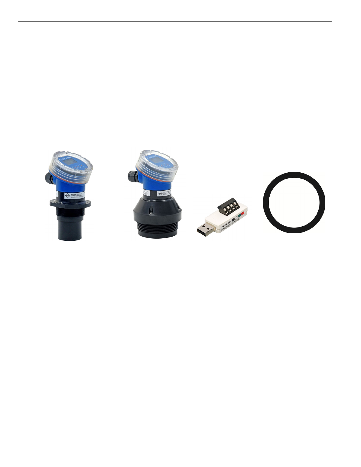
COMPONENTS
Depending on how the sensor part number that was shipped, EchoPod
®
comes with a Viton® gasket for
installation and the Quick Start.
®
EchoPod
UG06-0001-00
UG06-0001-01
UG06-0011-00
UG06-0011-01
EchoPod
®
UG12-0001-00
UG12-0001-01
UG12-0011-00
UG12-0011-01
®
USB
Key Fob
P/N: LI99-2001
Viton® gasket (2”)
G threaded version only
Viton® gasket (3”)
P/N: 200129
P/N: 210157
G threaded version only
ENCLOSURE
While the switch housing is liquid-resistant the EchoPod
®
is not designed to be operational when immersed. It
should be mounted in such a way that the enclosure and transducer do not come into contact with the
application media under normal operational conditions. Before closing the enclosure, make sure that the
enclosure gasket is properly seated, and that any conduit fittings, cable connectors or plugs are installed
correctly and sealed. Note: If using the Flowline LM90-1001 (liquid tight fitting) on the ½” conduit, the cable
minimum is 0.170” (4.3mm) and the maximum is 0.450” (11.4mm).
CONFIGURATION
When configuring EchoPod
®
, choose either the WebCal® or Push Button method. Either method will
accomplish the goal of sensor configuration. Changes to the configuration can be made using the alternative
method. When beginning with one method, it is recommended to complete the configuration before using the
other method to make any adjustments.
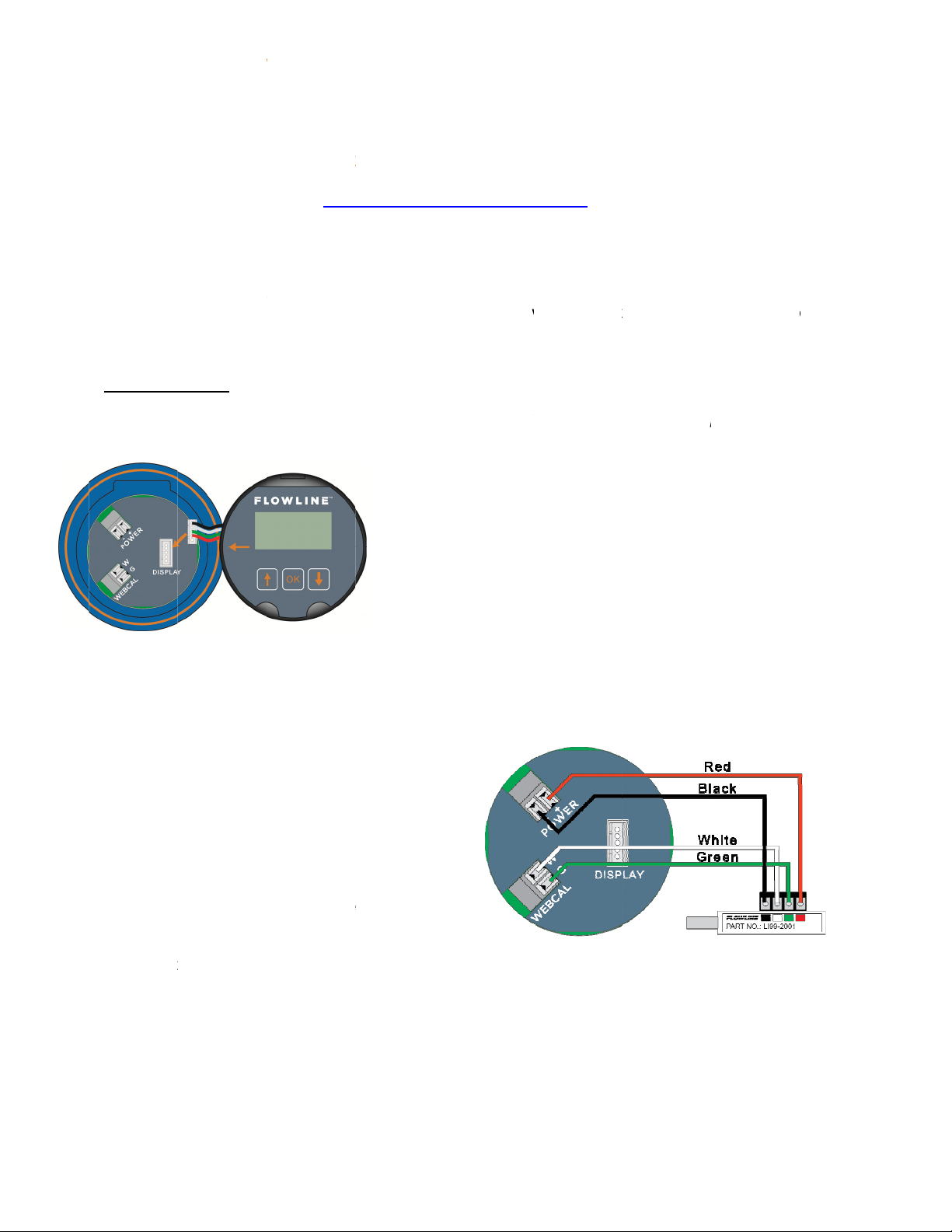
Note: When connecting the sensor to the WebCal
®
Software, you must remove the display or the software will
not connect. Once completed, you can re-connect the display to the terminal.
| 2 QS310140 Rev A4
Page 3
0
CO
N
o
o
P
w
c
d
a
P
e
e
c
B
c
E
n
L
C
a
b
C
o
n
n
u
n
o
n
o
t
w
W
o
r
t
e
B
F
e
x
®
p
t
p
)
i
o
W
a
q
E
w
a
e
e
c
h
o
t
e
p
r
s
e
n
w
U
f
e
2
w
n
t
n
u
o
M
C
w
y
t
g
u
o
.
t
m
n
g
o
o
t
W
o
p
b
u
s
e
g
d
s
c
e
y
d
FIGURING
Ech
perf
STE
Do
nload Web
spe
Win
Pod® is co
rmed prior
1: INSTAL
ifications:
ows® XP/V
CHOPOD® (
figured thr
to mounting
WEBCAL
al® softwa
ista/7/8/10,
EBCAL)
ugh WebC
, since it re
®
SOFTWAR
e from ww
10 MB stor
l®, a PC so
uires conn
.flowline.co
ge space,
tware progr
ction to yo
m/webcal-s
56 MB RA
am. Config
r PC.
ftware ont
, 1 USB® 2
ration of y
a PC with
0 port
ur sensor s
he followin
hould be
minimum
must have
You
inst
ll software
STE
2: CONNE
Not
: Do not c
Not
: When co
not
onnect. O
The
sensor com
®
US
the
omputer a
port, ens
1. Rem
from
n active In
efore proc
T THE US
nnect the
necting the
ce complet
municates t
re that all e
d EchoPod
ve the dis
the connec
ernet conn
eding to St
®
FOB
ob to your
sensor to t
d, you can
WebCal®
ternal pow
is 15’.
lay and un
or on the ci
ction to do
p 2. Install
omputer u
e WebCal®
re-connect
hrough the
r is discon
lug the cabl
cuit board.
nload Web
er program
til after you
Software,
he display
USB® Fob.
ected from
e
al®. Doubl
ill automa
’ve installed
ou must re
o the termi
Prior to plu
EchoPod®.
e-click the
ically install
WebCal
®
s
ove the dis
al.
ging the Fo
The maxim
ebCal® ins
any require
ftware.
lay or the
into your
m distanc
taller to
drivers.
oftware will
omputers
between
QS31
2. Con
3. Tigh
4. Plug
140 Rev A4
ect the pro
Ech
Pod® to the
nals on the
termi
. Power (+
a
. Power (-)
b
. WebCal (
c
. WebCal (
d
en the term
scre
the Fob int
driver.
er terminal
correspond
Fob.
to Red
to Black
W) to Whit
G) to Gree
nal screws
your PC’s
from the
ing colored
ith a slotte
SB® port.
d
Wirin
Black,
identical f
Green and
r all serie
White wir
– Use onl
s.
the Red,
3 |
Page 4
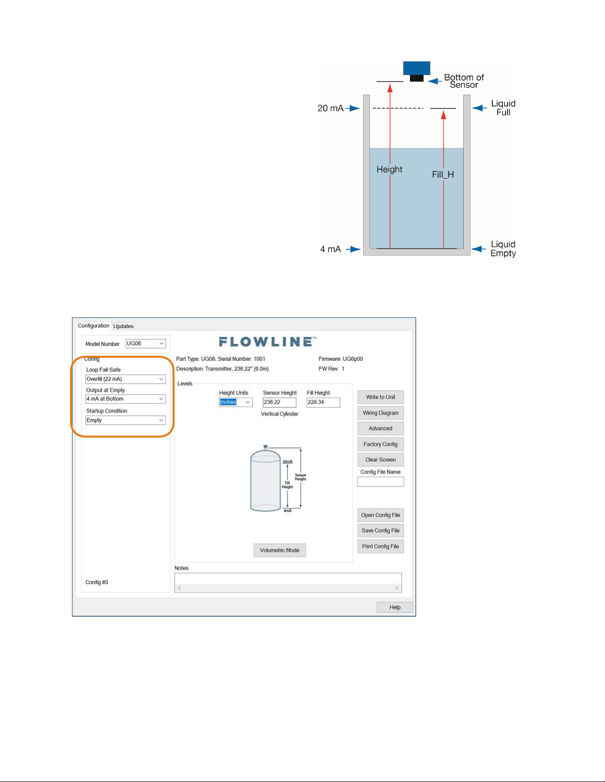
STEP 3 - MEASURE THE TANK
Measuring the tank is one of the most important aspects
in configuring the sensor. When measuring the tank,
take into account the location of the sensor with respect
to fittings, risers, dome tops and bottoms, and identify
where the measurements are taken from the sensor.
The HEIGHT and FILL-H settings determine the 420mA span and are always measured from the bottom
of the tank up.
STEP 4 - SENSOR CONFIGURATION
Configures the Loop Fail-Safe, Output at Empty and Startup Condition for the sensor.
| 4 QS310140 Rev A4
Page 5

STEP 5 – DIMENSIONAL ENTRY
Distance Mode (default): Output of sensor is based on the distance (height of liquid) in the tank. Any change
in liquid level will reflect linearly to the current output. The two values (Sensor Height and Fill-Height) below set
the 4-20 mA current span for the sensor. Both values will be set in the units shown under Height Units.
Height Units: Confirm units for use in Sensor Height and Fill-Height settings.
Sensor Height: Sets the location for 4mA. It is based on the distance from the Empty level position
(bottom of tank) to the Measurement location for the sensor (bottom of sensor).
Fill-Height: Sets the location for 20mA. It is based on the distance from the Empty level position
(bottom of tank) to the Full level position (see below).
STEP 6 - TANK LEVEL CONFIRMATION
Verify the Height Units, Sensor Height & Fill-Height. All values were calculated and set in the previous
Dimensional Entry window. Make any adjustments if required.
QS310140 Rev A4 5 |
Page 6

STEP 7 - WRITE TO UNIT
This WebCal®* operation uploads the configuration into the sensor, provides a custom wiring diagram specific
to the signal output and/or relay configuration, and saves the configuration file to your hard drive.
* For complete information on the WebCal
®
software, please refer to the WebCal® manual located at
flowline.com/webcal-software.
Before configuration can be completed:
You must click the Write to Unit button to save the settings to the unit.
Then, click Wiring Diagram for a hard copy of the sensor’s settings.
Finally, enter the file name under which you wish to save the configuration file and click Save Config
File.
Configuration is now complete.
Disconnect the USB
®
Fob before continuing to the next step: Mounting the EchoPod®.
| 6 QS310140 Rev A4
Page 7

CONFIGURING ECHOPOD® (DISPLAY)
TOP-LEVEL MENU
The sensor is configured with the three buttons on the sensor face (UP, DOWN and OK) and the sensor’s
LCD. To access the sensor’s Top-level menu, simply hold down the OK button for five seconds. The display
menu will automatically begin to scroll through the TOP-LEVEL MENU.
When the menu scrolls to an item you wish to configure, simply press the OK button to choose that item. The
TOP-LEVEL MENU will continue to scroll through the following (UNITS – TANK – dISPLY – OUTPUT –
VALUES – RUN), If you miss your selection, it will appear again shortly.
To return to the TOP-LEVEL MENU, press OK when EXIT appears.
To return to Operational Mode of the sensor, press OK when RUN appears in the TOP-LEVEL MENU.
Note: To speed up the scrolling of the values on the display, hold down the OK button while holding
down the UP or DOWN buttons.
STEP 1 - MEASURE THE TANK
Measuring the tank is one of the most important aspects in
configuring the sensor. When measuring the tank, take into
account the location of the sensor with respect to fittings, risers,
dome tops and bottoms, and identify where the measurements
are taken from the sensor. The HEIGHT and FILL-H settings
determine the 4-20mA span and are always measured from the
bottom of the tank up.
Height: Sets the location for 4mA. It is based on the distance
from the Empty level position (bottom of tank) to the
Measurement location for the sensor (bottom of sensor).
Fill-Height: Sets the location for 20mA. It is based on the
distance from the Empty level position (bottom of tank) to the
Full level position (see below).
#2 - SETTING THE UNITS OF MEASUREMENT (UNITS)
The EchoPod® displays information in the following units:
inches, feet, centimeters, meters or percentage. The value
shown on the display represents the amount of liquid in the
tank.
1) In TOP-LEVEL MENU mode, select UNITS.
2) Next, select INCHES, FEET, CM or METERS by holding
down OK button.
3) Finally, select EXIT to return to the TOP-LEVEL MENU.
QS310140 Rev A4 7 |
Page 8

#3 - SETTING THE HEIGHT (SENSOR HEIGHT) & #4 - SETTING THE FILL-H (FILL-HEIGHT)
This setting customizes the reading for your installation.
Follow these instructions to set the height and fill height for your tank:
1) In TOP-LEVEL MENU mode, select TANK.
2) Select HEIGHT.
3) Use the UP and DOWN buttons, set the
HEIGHT of your tank.
4) To enter the value, press and hold OK for 3
seconds and release. SAVED will display.
HEIGHT is now set.
5) Select FILL-H.
6) Use the UP and DOWN buttons, set the
HEIGHT of your tank.
7) To enter the value, press and hold OK for 3
seconds and release. SAVED will display.
FILL-H is now set.
8) Select EXIT to return to the TOP-LEVEL MENU.
9) Select RUN to return to Operational Mode.
Note: The Height and Fill Height settings also determine the 4 to 20 mA current span.
The Height setting determines the 4mA position and the Fill-H setting determines the 20 mA position.
#5 - HOW TO SELECT FAIL-SAFE CURRENT OUTPUT (LOST)
In the event the sensor does not receive an echo,
the Fail-Safe Current Output or LOST setting can
be set to output a current of 4mA, 20mA, 21mA,
22mA or HOLD (last known value). During failsafe, the display will read LOST.
1) In TOP-LEVEL MENU mode, select SAFE.
2) Select 4mA, 20mA, 21mA, 22mA or
HOLD by holding down OK button.
3) Select EXIT to return to the TOP-LEVEL
MENU.
TROUBLESHOOTING
If you face any issues not addressed in this Quick Start, please refer to the EchoPod
Flowline’s website at www.flowline.com.
®
Manual located on
| 8 QS310140 Rev A4
Page 9

0
MO
U
b
u
h
f
M
t
a
r
b
e
p
p
o
e
o
o
r
w
e
s
e
d
0
b
h
f
m
”
t
t
o
e
a
f
f
r
,
h
a
m
n
0
d
w
p
s
r
h
c
a
f
o
e
t
2
e
m
k
s
a
f
p
-
s
M
e
s
p
e
"
H
k
e
t
o
u
n
e
s
0
G
u
a
o
a
o
I
a
h
e
MLMLM
n
e
e
NTING ECH
The
sensor sho
or o
stacles in t
man
ual at www.
OPOD®
ld always
e path of t
lowline.co
e mounted
e acoustic
.
erpendicul
ignal. For
r to the liq
urther mou
id surface.
ting inform
nsure that t
tion, pleas
ere are no
refer to th
restrictions
EchoPod®
Installat
Use a L
slip x 3”
Basic T
Use a 2”
for the U
3890 for
Use a la
reducer
Use a 2”
UG06 s
for the U
Weld a
half cou
Mountin
Installati
2" diam
risers sh
Height t
Diamete
Installat
Use Flo
Not
for u
Ther
stan
ion in exist
52-2800 3
hread adap
nk Installa
bulkhead fi
G06 series
the UG12 s
ger bulkhe
ushing suc
flange with
ries or a 3”
G12 series.
lastic 2” hal
ling for the
g in Rise
ns with tall
ter risers s
uld be no t
Inner Dia
).
ion in ope
line's LM5
: The Side
e with stan
are too fe
pipe.
ing 3” fittin
thread x 2”
te
(UG06 s
ion:
ting, such a
r a 3” bulk
ries.
d fitting, su
h as the LM
a 2” thread,
lange with
coupling t
UG12.
:
narrow ris
ould be no
ller than 1
eter ratio (
tanks and
-1001 side
Mount Brac
pipes or a
threads to
gs:
thread ada
eries only).
s the LM52
ead fitting,
h as the L
52-2800.
such as th
3” thread
the tank to
rs can imp
aller than 4
". For best
xample: 8”
sumps:
ount brac
et (LM50 s
a method
properly h
ter or a LM
2890 bulkh
uch as the
52-3890 wi
LM52-285
uch as the
for the U
de the aco
. Larger di
results, foll
igh to 4” In
et.
ries) is not
o secure st
ld the sens
52-2810 3”
ad fitting
LM52-
th a
for the
LM52-3850
06 or a 3”
stic signal.
meter
w a 2:1
ner
designed
nd pipes.
r and the
L
52-2800
52-2890
52-2850
Mou
LM50-1
01
ting in Ris
QS31
140 Rev A4
9 |
Page 10

IMPORTANT MOUNTING GUIDELINES
1) Never mount the sensor at an angle.
2) Liquid should never enter the dead band.
3) Mount at least 3” from the side wall.
4) Never mount the sensor in a vacuum.
5) Do not obstruct the sensor’s beam width with objects underneath the sensor.
6) Do not mount in the center of a dome top tank.
7) In a cone bottom tank, position the sensor over the deepest part of the tank.
8) Avoid mounting in a riser where the sensor is recessed more than twice the diameter of the riser.
MOUNTING IN A STAND-PIPE
A stand-pipe may be used to dampen turbulence, separate surface foam from the point of measurement or
increase performance in heavy vapor. When mounting the sensor in a stand-pipe, the minimum diameter of the
pipe is 3”, minimum 4” for the UG12 series. Larger diameter pipes can be used. The pipe should be attached
with a coupling or tank adapter and reducer bushing. Avoid the use of multiple pipe fittings when possible. An
ideal mount would be to select a tank adapter (S x T or S x S) and connect the pipe to the inside slip and use a
reducer bushing to attach the sensor (see example below).
The pipe length should run the measurement span and the bottom of the pipe should remain submerged at all
times to prevent foam from entering the pipe. Cut the bottom end of the pipe at 45° and drill a 1/4” pressure
equalization hole within the sensor’s dead band. Locate the stand-pipe away from pump outlets and/or other
sources of substantial turbulence which might cause the liquid in the pipe to oscillate.
3” x 2”
Reducer Bushing
(TxT)
3” Tank
Adapter
(S x T)
3” PVC Pipe
Stand-Pipe Example
Stand-Pipe Mounting
| 10 QS310140 Rev A4
Page 11

WIRING THE ECHOPOD®
The following wiring diagram can be used for the 4-20 mA output of the EchoPod
®
.
Notes on Safety
Where personal safety or significant property damage can occur due to a spill, the installation must
have a redundant backup safety system installed.
Wiring should always be completed by a licensed electrician.
The sensor must be chemically compatible with the application.
Design a fail-safe system for possible sensor and/or power failure.
Never use the sensor in classified hazardous environments.
Wiring to Common Devices
Wiring to Loop Display Wiring to Generic PLC
Wiring to DataView™
LI55 series
QS310140 Rev A4 11 |
Page 12

WARRANTY
Flowline warrants to the original purchaser of its products that such products will be free from defects in
material and workmanship under normal use and service in accordance with instructions furnished by Flowline
for a period of two years from the date of manufacture of such products. Flowline's obligation under this
warranty is solely and exclusively limited to the repair or replacement, at Flowline's option, of the products or
components, which Flowline's examination determines to its satisfaction to be defective in material or
workmanship within the warranty period. Flowline must be notified pursuant to the instructions below of any
claim under this warranty within thirty (30) days of any claimed lack of conformity of the product. Any product
repaired under this warranty will be warranted only for the remainder of the original warranty period. Any
product provided as a replacement under this warranty will be warranted for the full two years from the date of
manufacture.
RETURNS
Products cannot be returned to Flowline without Flowline's prior authorization. To return a product that is
thought to be defective, go to flowline.com, and submit a customer return (MRA) request form and follow the
instructions therein. All warranty and non-warranty product returns to Flowline must be shipped prepaid and
insured. Flowline will not be responsible for any products lost or damaged in shipment.
LIMITATIONS
This warranty does not apply to products which: 1) are beyond the warranty period or are products for which
the original purchaser does not follow the warranty procedures outlined above; 2) have been subjected to
electrical, mechanical or chemical damage due to improper, accidental or negligent use; 3) have been modified
or altered; 4) anyone other than service personnel authorized by Flowline have attempted to repair; 5) have
been involved in accidents or natural disasters; or 6) are damaged during return shipment to Flowline. Flowline
reserves the right to unilaterally waive this warranty and dispose of any product returned to Flowline where: 1)
there is evidence of a potentially hazardous material present with the product; or 2) the product has remained
unclaimed at Flowline for more than 30 days after Flowline has dutifully requested disposition. This warranty
contains the sole express warranty made by Flowline in connection with its products. ALL IMPLIED
WARRANTIES, INCLUDING WITHOUT LIMITATION, THE WARRANTIES OF MERCHANTABILITY AND
FITNESS FOR A PARTICULAR PURPOSE, ARE EXPRESSLY DISCLAIMED. The remedies of repair or
replacement as stated above are the exclusive remedies for the breach of this warranty. IN NO EVENT SHALL
FLOWLINE BE LIABLE FOR ANY INCIDENTAL OR CONSEQUENTIAL DAMAGES OF ANY KIND
INCLUDING PERSONAL OR REAL PROPERTY OR FOR INJURY TO ANY PERSON. THIS WARRANTY
CONSTITUTES THE FINAL, COMPLETE AND EXCLUSIVE STATEMENT OF WARRANTY TERMS AND NO
PERSON IS AUTHORIZED TO MAKE ANY OTHER WARRANTIES OR REPRESENTATIONS ON BEHALF
OF FLOWLINE. This warranty will be interpreted pursuant to the laws of the State of California. If any portion
of this warranty is held to be invalid or unenforceable for any reason, such finding will not invalidate any other
provision of this warranty.
For complete product documentation, video training, and technical support, go to flowline.com.
For phone support, call 562-598-3015 from 8am to 5pm PST, Mon - Fri.
(Please make sure you have the Part and Serial number available.)
| 12 QS310140 Rev A4
 Loading...