

Page 1
EchoPod®
Ultrasonic Level Transmitter
UG01 & UG03 Series Manual
Flowline, Inc. | 10500 Humbolt Street, Los Alamitos, CA 90720 p 562.598.3015 f 562.431.8507 w flowline.com MN310125 Rev A3
Page 2

Introduction / Table of Contents Step One
An ultrasonic sound wave is pulsed from the base of the transducer. The sound wave reflects against the
process medium below it. The sound wave energy is returned to the transducer. The microprocessor based
electronics measures the time of flight between the sound pulse generation and its receipt. This translates into
the distance or range between the transducer and process media below.
NEW FEATURES
Reflective Ultrasonic Technology
Simple configuration with WebCal
®
software configuration
Increased temperature range
Increased output filtering
TABLE OF CONTENTS
Introduction: .......................................................................................................................................................... 2
Specifications: ........................................................................................................................................... 4
Dimensions: .............................................................................................................................................. 5
About this manual: .................................................................................................................................... 6
Getting Started: ..................................................................................................................................................... 7
Setup Overview: ........................................................................................................................................ 7
Reflective Technology: .............................................................................................................................. 7
Components: ............................................................................................................................................. 8
Basic Configuration: .................................................................................................................................. 9
Basic Relay Settings: ................................................................................................................................ 9
Understanding Sensor Height: ................................................................................................................ 10
Understanding Fill-Height: ................................................................................................................. 11-12
Sensor Output to Local Display: ............................................................................................................. 13
Configuration: .................................................................................................................................................... 14
Configuring EchoPod
®
with WebCal: ...................................................................................................... 14
Step 1 – Install WebCal Software: .......................................................................................................... 15
WebCal System Requirements: .................................................................................................. 15
USB
®
Fob (LI99-2001) Interface: ................................................................................................ 16
Step 2 – Measure the Tank: .................................................................................................................... 17
Step 3 – Sensor Configuration: ............................................................................................................... 18
Step 4 – Dimensional Entry: ................................................................................................................... 19
Step 5 – Tank Level Confirmation: .......................................................................................................... 20
Step 6 – Write to Unit: ............................................................................................................................. 20
Installation: .......................................................................................................................................................... 21
Mounting Guide: ...................................................................................................................................... 21
Fitting Selection: ................................................................................................................................ 22-24
| 2 MN310125 Rev A3
Page 3

Introduction / Table of Contents Step One
Wiring: ................................................................................................................................................................. 25
Wiring Diagram – Sample: ...................................................................................................................... 25
Wiring EchoPod
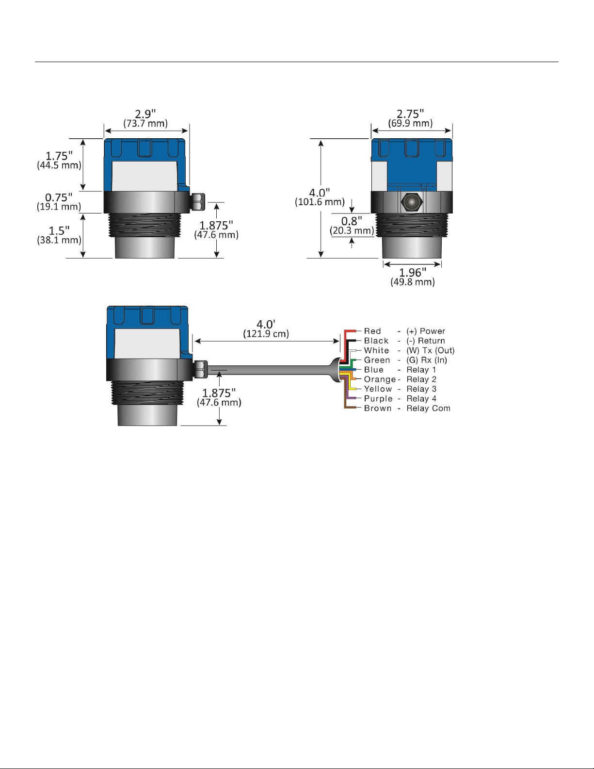
Wire Connections: ................................................................................................................................... 26
General Notes for Electrical Connections, Usage and Safety: ............................................................... 26
Common Wiring to Displays, Controllers & PLCs: ............................................................................. 27-28
Switching Inductive Loads: ..................................................................................................................... 29
Voltage Output: ....................................................................................................................................... 29
WebCal
®
Appendix: ............................................................................................................................................ 30
Sensor Configuration: ........................................................................................................................ 30-36
Number of Pumps: ...................................................................................................................... 30
Pump/Valve Action: ..................................................................................................................... 31
Pump/Valve Mode: ...................................................................................................................... 32
Relay Fail-Safe: ........................................................................................................................... 33
Switch/Alarm Configuration: ........................................................................................................ 34
Switch Hysteresis/Dead Band: .................................................................................................... 35
Loop Fail-Safe: ............................................................................................................................ 36
Output at Empty: ......................................................................................................................... 36
Volumetric Configuration: ................................................................................................................... 37-39
Tank Level Confirmation: ........................................................................................................................ 40
Write to Unit” ........................................................................................................................................... 41
Appendix: ............................................................................................................................................................ 42
Factory Settings: ..................................................................................................................................... 42
User Settings: ......................................................................................................................................... 42
Troubleshooting: ..................................................................................................................................... 43
Warranty: ............................................................................................................................................................ 44
®
..................................................................................................................................... 25
MN310125 Rev A3 3 |
Page 4

Introduction (continued) Step One
SPECIFICATIONS
Electrical:
Supply Voltage: 14-28 Vdc
Signal output: 4 to 20 mA current loop; 22 mA
max.
Signal invert: 4-20mA or 20-4mA
Signal fail-safe: 4mA, 20mA, 21mA, 22mA or
hold last value
Loop resistance: 500 Ohms @ 24 VDC
Contact type: (4) SPST relays, 1A
Contact fail-safe: Power loss: Hold last
Power on: Open, close or hold
last
Hysteresis: Selectable
Mechanical:
Enclosure: Polypropylene (PP-FR GF30)
Transducer: Polyvinylidene Fluoride (PVDF)
Environmental:
Process temperature: F: -40° to 176°
C: -40° to 80°
Temp. compensation: Automatic
Ambient temp.: F: -31° to 140°
C: -35° to 60°
Pressure: 30 psi, derated @ 1.667 psi per
degree C above 25 °C
Enclosure: IP68, NEMA 6P
Functional:
Range: UG01: 1.5m (4.92 feet)
UG03: 3.0m (9.84 feet)
Dead band: UG01: 3.8cm (1.5 inches)
UG03: 10cm (4 inches)
Accuracy: UG01: 0.125” (3mm)
UG03: 0.2% of Range in air at
Cable jacket mat’l: Polyurethane
Cable type: 9-conductor
Cable length: 4’ (121.9 cm)
Process Mount: 2" NPT or 2” G
Gasket Viton A (G thread only)
Resolution: 0.125" (3mm)
Beam width: 2” (5cm)
Configuration: WebCal
Memory: Non-volatile
Classification: General purpose
Compliance: CE, RoHS
20 °C
®
configuration software
| 4 MN310125 Rev A3
Page 5
Introduction (continued) Step One
DIMENSIONS
Dimensions for UG01 & UG03 Series
Cable Dimensions for UG01 & UG03 Series
MN310125 Rev A3 5 |
Page 6

Introduction (continued) Step One
About this Manual: PLEASE READ THE ENTIRE MANUAL PRIOR TO INSTALLING OR USING THIS
PRODUCT. This manual includes information on the EchoPod
®
series Ultrasonic Level Transmitter from
FLOWLINE. Please refer to the part number located on the sensor label to verify the exact model
configuration, which you have purchased.
User’s Responsibility for Safety: FLOWLINE manufactures a broad range of level sensing technologies.
While each of these sensors is designed to operate in a wide variety of applications, it is the user’s
responsibility to select a sensor model that is appropriate for the application, install it properly, perform tests of
the installed system, and maintain all components. The failure to do so could result in property damage or
serious injury.
Proper Installation and Handling: Only professional staff should install and/or repair this product. Never
over tighten the sensor within the fitting. Always check for leaks prior to system start-up.
Wiring and Electrical: A supply voltage of 14 to 28 VDC is used to power the EchoPod®. Electrical wiring
of the transmitter should be performed in accordance with all applicable national, state, and local codes.
Material Compatibility: The enclosure is made of Polypropylene (PP-FR GF30). The transducer is made
of Polyvinylidene Fluoride (PVDF). Make sure that the model, which you have selected, is chemically
compatible with the application media.
Enclosure: While the sensor housing is liquid-resistant the EchoPod® is not designed to be operational
when immersed. It should be mounted in such a way that the enclosure and transducer do not come into
contact with the application media under normal operational conditions.
Handling Static-Sensitive Circuits/Devices: When handling the transmitter, the technician should follow
these guidelines to reduce any possible electrostatic charge build-up on the technician’s body and the
electronic part.
1. Always touch a known good ground source before handling the part. This should be repeated while
handling the part and more frequently after sitting down from a standing position, sliding across the seat
or walking a distance.
2. Avoid touching electrical terminals of the part unless making connections.
Make a Fail-Safe System: Design a fail-safe system that accommodates the possibility of switch and/or
power failure. FLOWLINE recommends the use of redundant backup systems and alarms in addition to the
primary system.
Flammable, Explosive or Hazardous Applications:
EchoPod® should not be used within classified hazardous environments.
Warning: Always use the Viton® gasket when installing the “G” threaded version of EchoPod®.
Warning: Make sure that all electrical wiring of the switch is in accordance with applicable NEC codes.
| 6 MN310125 Rev A3
Page 7
Getting Started Section Two
SETUP OVERVIEW
Below highlights the initial steps in setting up your sensor for operation.
1. Check Part Number (Section Two)
a. Confirm that the sensor’s part number matches the ordered part number and all components
are provided with the model delivered.
2. Measurements, Installation & Software (Section Two)
a. Understand the location placement of the sensor relative to Measurement Range including
Sensor Height and Fill-Height settings.
b. Download the WebCal
3. Configure Sensor with WebCal
a. Section 3 contains information on using the WebCal
4. Install the sensor (Section Four)
a. Section 4 contains information about the sensor location placement and its mechanical
installation.
5. Wire the sensor (Section Five)
a. Section 5 contains information about the sensor’s electrical wiring and power requirements.
REFLECTIVE TECHNOLOGY
®
software from www.flowline.com/webcal-software/.
®
(Section Three)
®
configuration software.
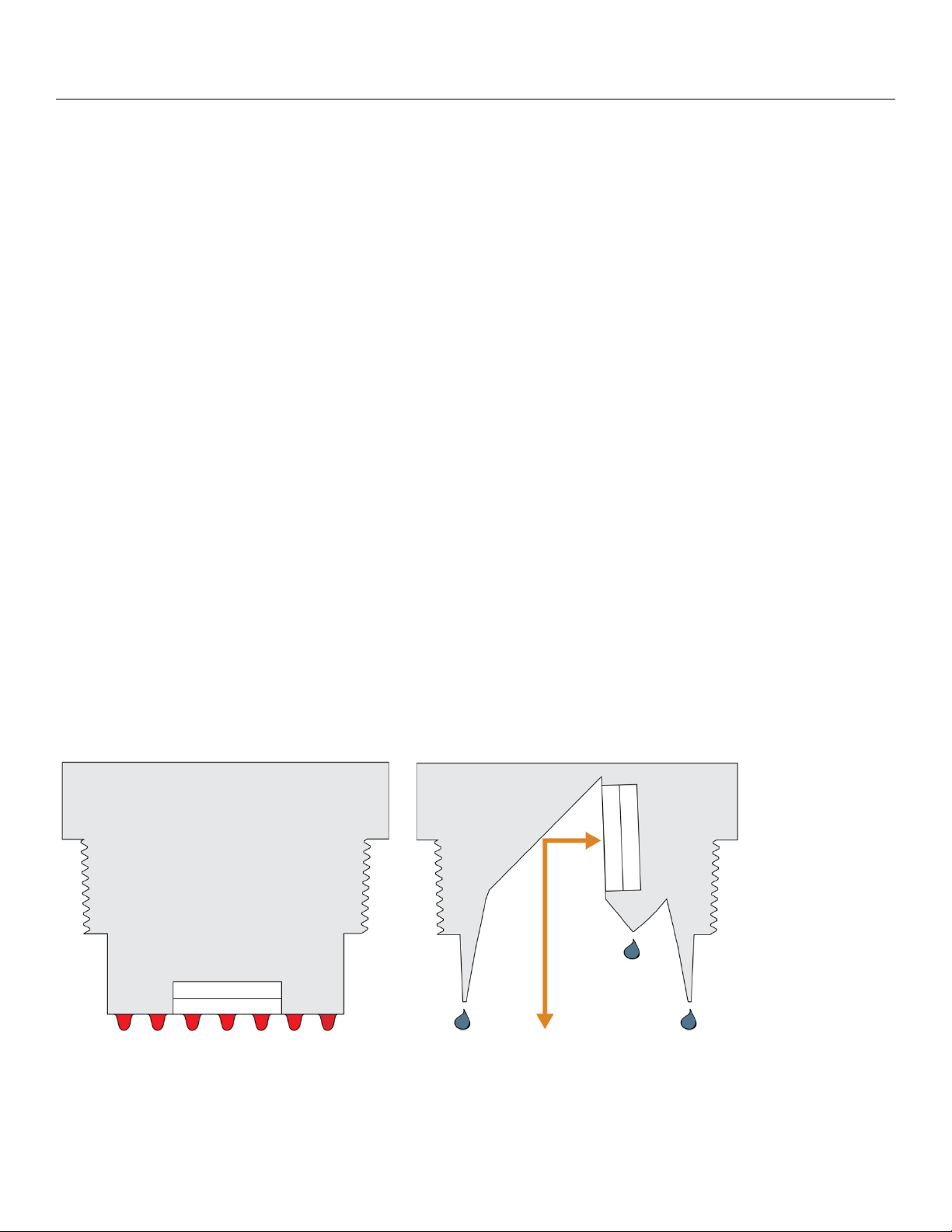
Condensation is the most common variable in liquid level applications. Condensation attenuates the acoustic
signal of ultrasonic sensors with horizontal transducers, weakening their signal strength and signal to noise
ratio by up to 50%, and substantially reducing their measurement reliability. At the core of Reflective
Technology™ is a simple fact. Unlike flat horizontal surfaces, significant water droplets cannot adhere to
smooth vertical surfaces. By orienting the transducer vertically, condensation runs off the transducer and does
not affect sensor performance. The unimpeded transmit and receive signals are redirected to and from the
liquid off a 45º reflector, delivering reliable level measurement.
FLAT TRANSDUCER REFLECTIVE TRANSDUCER
Signal Attenuation Reliable Measurement
MN310125 Rev A3 7 |
Page 8
Getting Started (continued) Section Two
COMPONENTS
EchoPod® is offered in two different models with 4-20 mA output and relay control. Depending on the model
purchased, you may or may not have been shipped all the components shown below. All G threaded process
mounts require a Viton
®
gasket for installation and operation of EchoPod®.
P/N
UG03-0001-40
Max.
Range
Dead
Band
Thread Fob Output Configuration
Not Included
2” NPT
UG03-0001-41 Included
UG03-0011-40
9.8’
(3m)
4”
(10cm)
Not Included
2” G
UG03-0011-41 Included
UG01-0001-40
Not Included
2” NPT
UG01-0001-41 Included
UG01-0011-40
4.9’
(1.5m)
1.5”
(3.81cm)
Not Included
2” G
UG01-0011-41 Included
®
Viton
Gasket (G threaded version only)
o Part #210138
Fob (UG0_-00_1-41 series only)
o Part #LI99-2001
Quick Start Guide
4-20mA
&
4 SPST
Relays
WebCal
®
only
| 8 MN310125 Rev A3
Page 9
Getting Started (continued) Step Two
BASIC CONFIGURATION
EchoPod® can be configured using the Flowline™ on-line free WebCal® software download coupled to a USB®
port with a USB
EchoPod
®
®
Fob.
can be configured before installation or after installation. The transmitter features non-volatile
memory, so any settings configured before installation will not be lost when the sensor is powered down To
start, the following information is required:
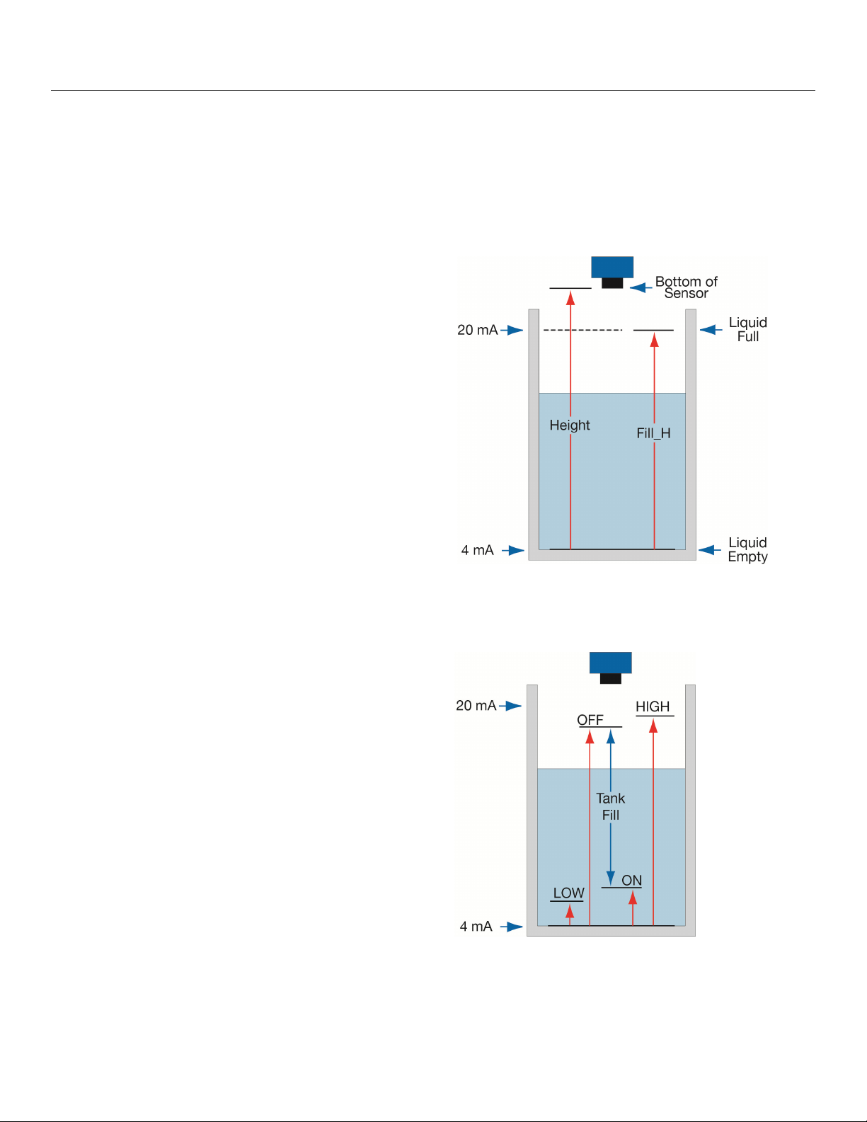
Basic Tank Information
o HEIGHT (Sensor Height) – Distance from
the bottom of the tank to the bottom of the
sensor.
o FILL-H (Fill-Height) – Distance from the
bottom of the tank to the fill-height of the
liquid.
Power:
o Provide input power to the EchoPod
®
Note: The HEIGHT and Fill-Height (FILL-H) settings also determine the 4 to 20 mA current span. The
HEIGHT setting determines the 4mA position and the FILL-H setting determines the 20 mA position.
BASIC RELAY SETTINGS
High Alarms (Hi) – Used to energize a relay
(ON) when the level reaches the Hi setting.
Relay will de-energize (OFF) when level falls
below the original setting.
Tank Fill (ON & OFF) – Used to automatically
fill a tank using only one relay. Relay
energize at ON level and remains energized
until it reaches the OFF level where it deenergizes. Relay remains de-energized until
the level falls below ON level.
Tank Empty (not shown) – is the exact
opposite of Tank Fill. One relay is used to
empty the tank with ON set to a high point in
the tank and OFF set to a low point.
Lo Alarms (Lo) – Used to energize a relay (ON) when the level falls below the Lo setting. Relay will
de-energize (OFF) when level rises above the original setting.
Note: All relay settings are referenced from the Empty or 4mA setting of the tank.
MN310125 Rev A3 9 |
Page 10
Getting Started (continued) Step Two
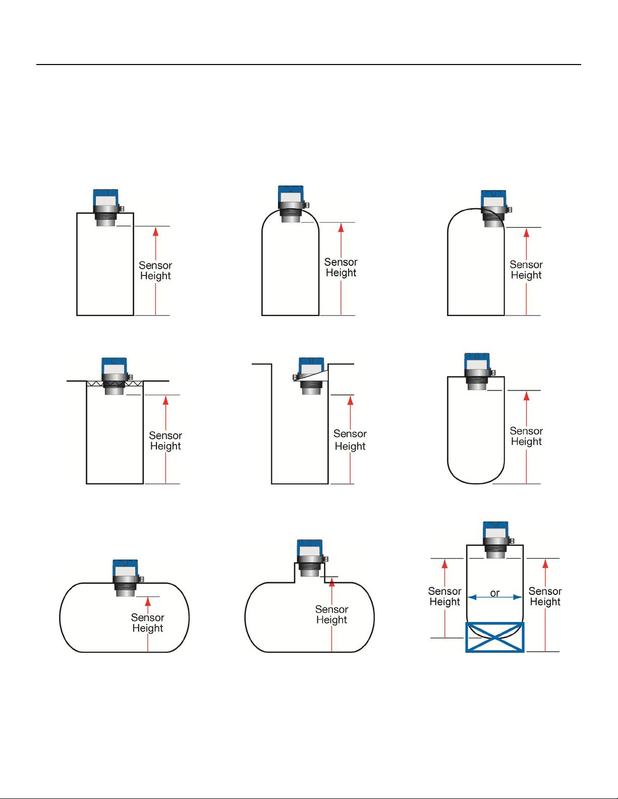
UNDERSTANDING SENSOR HEIGHT
This is a critical setting for EchoPod®. Sensor Height (SH) defines the location of the sensor from the bottom
of the tank. The value must take into account the shape of the tank and any risers, fittings, structures or
extensions associated with the tank or the installation (see examples below). The reference point for definition
of the Sensor Height is always the bottom of the mounting nut.
Sensor Off-center
Simple Vertical Tank Dome Top Raises HEIGHT
Changes HEIGHT
Simple Open Top Tank Sensor Extends into Sump
Simple Horizontal Tank Riser Elevates HEIGHT
Cone Bottom
Elevates HEIGHT
Mounting Fixture
Elevates HEIGHT
| 10 MN310125 Rev A3
Page 11
Getting Started (continued) Step Two
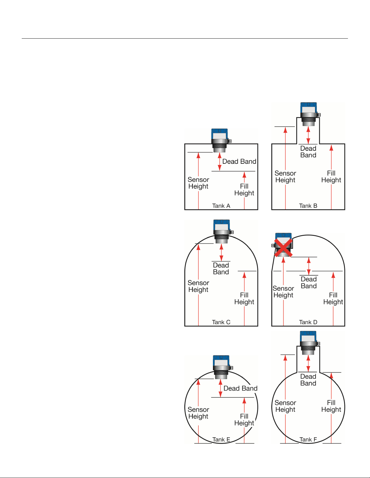
UNDERSTANDING FILL-HEIGHT
This is another critical setting for EchoPod®. Fill-Height defines the location of the highest point in the tank
where the sensor will read level changes. When the level rises above Fill-Height, the sensor will read full (as
long as the level does not enter the dead band). The reference point for definition of Fill-Height is always from
the bottom location of the Sensor Height. The value must take into account the sensors dead band, any risers,
fittings, structures or extensions associated with the tank or the installation as well as the tanks geometry.
Example #1 – Flat Top Tanks
Tank A is a vertical tank with a flat top. The
highest value for Fill-Height can be calculated by
subtracting the Dead Band from the Sensor Height.
Fill-Height = Sensor Height – Dead Band
Tank B is another vertical tank with a riser that
matches the dead band of the sensor. In this case,
the Fill-Height will be set to the top of the tank.
Note: The ratio of height to diameter of the riser
must be no greater than 2:1. Any higher and the
sensor will target the inside wall of the riser.
Example #2 – Dome Top Tanks
Tank C has a tall enough dome whereas the Dead
Band is above the straight side of the tank. The
Fill-Height can be set to the top of the straight side
(this is advantageous because the top of the
straight side is typically a known volume of liquid).
The sensor is moved to a flat part of Tank D. As a
result, the Dead Band is now below the straight
side of the tank. Fill-Height cannot be set to match
the straight side of the tank. Calculate Fill-Height
as follows:
Fill-Height = Sensor Height – Dead Band
Example #3 – Horizontal Tanks
Tank E is a horizontal tank with a rounded top.
The highest value for Fill-Height can be calculated
by subtracting the Dead Band from the Sensor
Height.
Fill-Height = Sensor Height – Dead Band
Tank F is another horizontal tank with a riser that
matches the dead band of the sensor. In this case,
the Fill-Height will be set to the top of the tank.
Note: The ratio of height to diameter of the riser
must be no greater than 2:1. Any higher and the
sensor will target the inside wall of the riser.
MN310125 Rev A3 11 |
Page 12
Getting Started (continued) Step Two
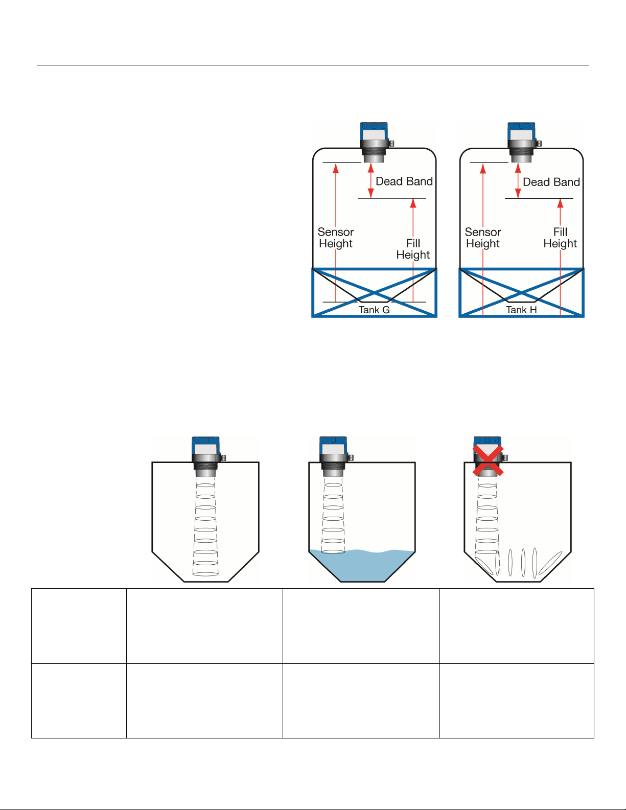
Example #4 – Cone Bottom Tank
Tank G and Tank H are both vertical tanks that are
being supported above ground level with tank
stands. The location of the Sensor Height (Tank G
- bottom of tank or Tank H – ground level) will
influence the Fill-Height setting.
Note: Fill-Height must always be referenced to the
lowest location of the Sensor Height.
Since Tank G is off of the ground, the lowest
location may be difficult to identify/measure. This
location is required if the Volumetric Mode in
WebCal
Tank H uses ground level as the main reference
location. This method is easiest to use and ideal
for using the Distance Mode of WebCal
®
is used.
®
.
Cone and Rounded Bottom Tanks
The location of an EchoPod
®
installed along the top of a cone or rounded bottom tank may have an effect on
the installation of the sensor. Be sure to understand the geometry directly underneath the sensor. Cone or
rounded bottom tanks will provide off angled surfaces that can reflect the ultrasonic sound energy away from
the sensor as the liquid level is lowered.
#1 Center of Cone #2 Above an Angled Tank
Bottom (straight side only)
#3 Above an Angled Tank
Bottom (full range)
Tank
Geometry
Does not impede sensor’s
performance. Sensor is able
to track the entire range of
the tank.
Does not impede sensor’s
performance as long as the
level remains within the
straight side of the tank wall.
Does impede sensor’s
performance. The angled
bottom will reflect ultrasonic
energy away from the
sensor.
Distance
Reading
Sensor Height is typically
set to the bottom of the tank.
Sensor will track the full
range of the tank.
Sensor Height is typically
set to the bottom of the
straight side. Sensor will
only tack the straight side of
the tank.
Sensor Height is set to the
bottom of the tank; the
sensor will function as long
as the level is within the
straight side of the tank.
| 12 MN310125 Rev A3
Page 13
Getting Started (continued) Step Two
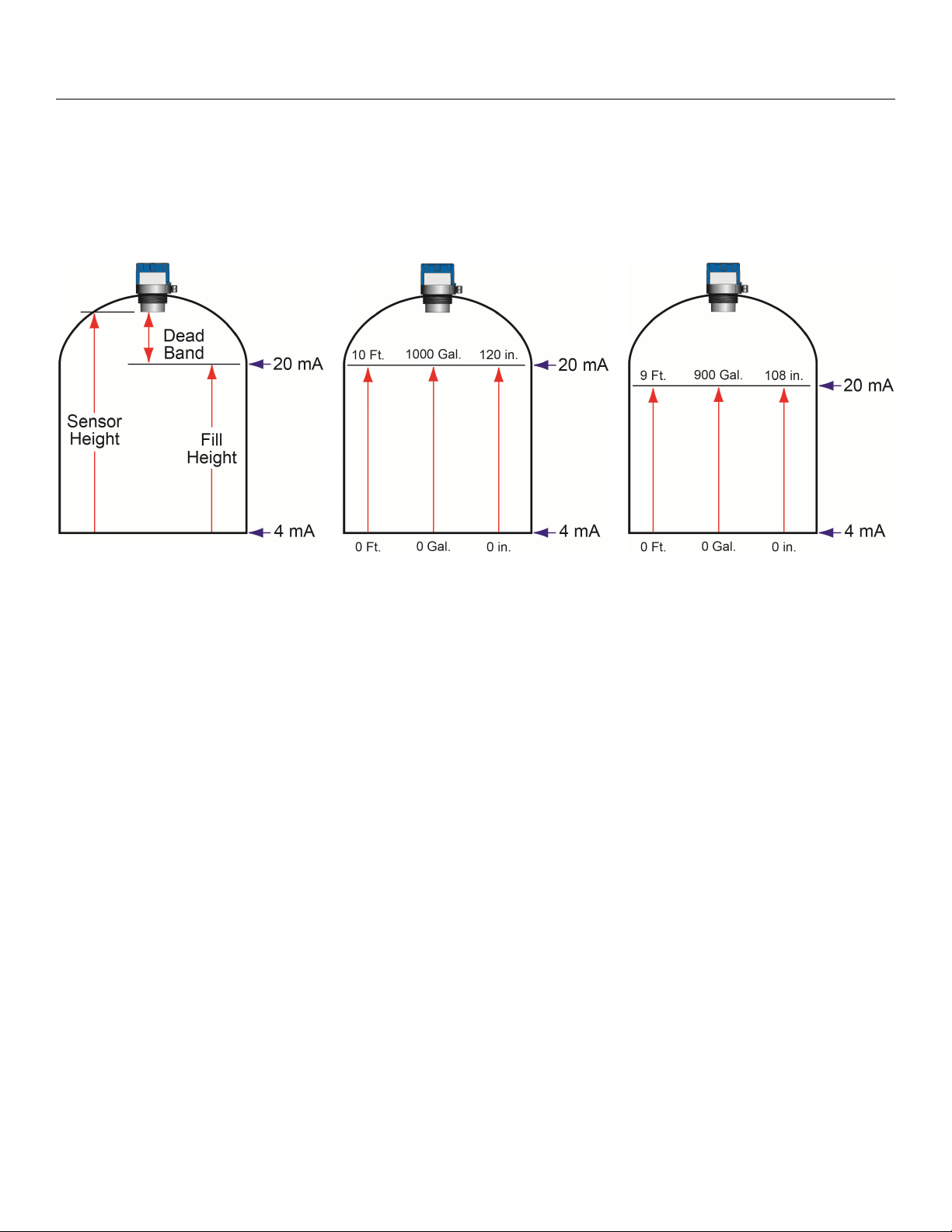
SENSOR OUTPUT TO LOCAL DISPLAY/CONTROLLER
EchoPod® outputs a 4-20 mA signal to a local display/controller or to remote devices such as PLCs, SCADA,
DCS or other displays/controllers. The 4-20 mA signal is set relative to the Sensor Height and Fill-Height
settings. These settings create an operational range that can be translated into a level reading in defined units
(i.e. inches, feet, gallons, meters, liters, etc.).
Tank A
In the Tank A example, the Sensor Height sets the 4mA to the bottom of the tank. Fill-Height sets the 20mA to
the top of the straight side of the tank.
In the Tank B example, the 4-20mA sensor range is correlated to actual units of level measurement. The
operational range now will have engineering values of 0 to 10 feet or 0 to 1000 gallons or 0 to 120 inches.
In the Tank C example, the 20mA setting was lowered by 1 foot, so the engineering values for the new shorter
operational ranges are either 0 to 9 feet, 0 to 900 gallons or 0 to 108 inches.
Tank B
Tank C
MN310125 Rev A3 13 |
Page 14

Configuration Step Three
EchoPod
®
can be configured before installation. The transmitter features non-volatile memory, so any setting
configured before installation will not be lost when the switch is powered down. To configure, follow the steps
below:
1. Install WebCal
a. Go to www.flowline.com/webCal-software/
b. Review how USB
®
software
®
and select language version.
Fob interfaces with EchoPod® and your computer.
2. Measure the Tank
a. Begin by measuring the key tank and fitting dimensions.
b. Include all settings for each relay.
c. Correct tank dimensions will result in accurate sensor measurement.
3. Sensor Configuration
a. Configures Number of Pumps, Pump/Valve Action, Pump/Valve Mode, Relay Fail-Safe,
Switch/Alarm Configuration, Switch Hysteresis/Dead Band, Loop Fail-Safe & Output at Empty for
the sensor.
4. Dimensional Entry
a. Distance Mode (default)
i. Basic information for operation (Sensor Height & Fill-Height).
ii. Relay activation settings.
5. Tank Level Confirmation
a. Confirm the values are accurate for the application.
6. Write to Unit
a. Uploads configuration into the sensor.
b. Access to a customer wiring diagram specific to the relay configuration.
| 14 MN310125 Rev A3
Page 15

Configuration (continued) Step Three
STEP 1 – INSTALL WEBCAL® SOFTWARE
EchoPod® is configured through WebCal®*, a PC software program. WebCal® is a free download from
®
Flowline’s website. You must download and install WebCal
prior to plugging in the USB® Fob (LI99-
2001). Please go to .flowline.com/webcal-software/, and select your language version.
WEBCAL® SYSTEM REQUIREMENTS
Windows® XP, Vista, 7, 8, 10
32 or 64-bit system
1 USB
®
2.0 port
10 mB hard drive space
256 mB RAM
Internet connection
*
For complete information on the WebCal
®
software, please refer to the WebCal® manual located at
www.flowline.com/webcal-software/.
MN310125 Rev A3 15 |
Page 16

®
Configuration (continued) Step Three
USB® FOB INTERFACE
EchoPod
your Fob into your computer’s USB
www.flowline.com/webcal-software/
Connect the red, green, white and black wires from EchoPod
the screws on the terminals. Plug your Fob into the USB
®
communicates with WebCal®* through a USB® interface called a Fob (LI99-2001). Before plugging
®
port, be sure that you have installed WebCal® (see
) on your computer.
®
port of your computer.
Wiring to Fob (LI99-2001)
Wiring is identical for all EchoPod
®
Series – Use only the Red, Black, Green and White wires.
®
into the correct terminals on the Fob. Tighten
LI99-2001 USB
Fob
Note: Only use the LI99-2001 USB®
Fob (white). The LI99-1001 USB
(black) will not work with the
EchoPod
®
series.
®
Fob
®
The maximum cable distance between the computer and EchoPod
the EchoPod
Once EchoPod
®
.
®
is configured and prior to installation, isolate the white and green wires from active power
is 15’. This only applies for configuring
to prevent a short from the configuration circuit.
Note: When using the Fob, do not add VDC or VAC power. The Fob, when connected to the computer, will
provide the required power to the EchoPod
* For complete information on the WebCal
®
.
®
software, please refer to the WebCal® manual located at
www.flowline.com/webcal-software/.
| 16 MN310125 Rev A3
Page 17

Configuration (continued) Step Three
STEP 2 - MEASURE THE TANK
Measuring the tank is one of the most important aspects in
configuring the sensor. When measuring the tank, take
into account the location of the sensor with respect to
fittings, risers, dome tops and bottoms, and identify where
the measurements are taken from the sensor. The Sensor
Height is influenced by the installation location. Sensors
mounted along the sloped portion of the tank will result in a
lower (HEIGHT) value. On the other hand, sensors
installed in risers/nozzles will result in a higher (HEIGHT)
value.
The basic measurements (Height and Fill-H) for configuration are described below:
1. HEIGHT (Sensor Height) - Distance from the bottom of
the tank to the Bottom of Sensor.
a. The bottom of the tank will be the sensor’s zero
level / empty level.
b. This setting determines the 4mA location.
2. FILL-H (Fill-Height) - Distance from the bottom of the
tank to the level of liquid where the tank is full is FILL-H.
a. The FILL-H is typically set to the liquid full level.
b. This setting determines the 20 mA location.
c. 20mA cannot be set within the sensor’s dead
band [8” (20cm) from bottom of sensor]. Largest
FILL-H value will be as follows:
Largest FILL-H = HEIGHT – 8” (20cm)
3. Relay Set Points – Distance from the bottom of the tank
to the level of liquid where each relay activates.
a. Pumps/Valves have two set points, one for ON
and the other for OFF.
b. Alarms have one set point which can be used as
a high alarm (energized with level above set
point) or a low alarm (energized with level below
set point).
c. Independent Relays each have two set points,
one for ON and the other for OFF.
MN310125 Rev A3 17 |
Page 18

Configuration (continued) Step Three
With EchoPod
Follow steps 1-4 to configure the transmitter. Click “Help” in the lower right hand corner and open the help
menu of WebCal
contact a Flowline sales applications engineer at (562) 598-3015. Note: For complete information on the
WebCal
STEP 3 – SENSOR CONFIGURATION:
®
®
connected to your computer, open the WebCal®* software by clicking on the WebCal® icon.
®
for instructions on WebCal®. If you need additional assistance using WebCal®, please
software, please refer to the WebCal® manual located at .flowline.com/webcal-software/.
Configures the relays in terms of pump/valve operations and level alarms as well as the setting fail-safe for
relays and signal output. Refer to SENSOR CONFIGURATION on page 30 for detailed information on the
different settings.
| 18 MN310125 Rev A3
Page 19

Configuration (continued) Step Three
STEP 4 – DIMENSIONAL ENTRY:
Distance Mode (default): Output of sensor is based on the distance (height of liquid) in the tank. Any
change in liquid level will reflect linearly to the current output. Note: Most applications will fall into this
category. For Volumetric outputs, refer to VOLUMETRIC CONFIGURATION on page 40. The two
values (Sensor Height and Fill-Height) below set the 4-20 mA current span for the sensor. Both values
will be set in the units shown under Height Units.
Height Units: Confirm units for use in Sensor Height and Fill-Height settings.
Sensor Height: Sets the location for 4mA. It is based on the distance from the Empty level
position (bottom of tank) to the Measurement location for the sensor (bottom of sensor).
Fill-Height: Sets the location for 20mA. It is based on the distance from the Empty level
position (bottom of tank) to the Full level position (see below).
Relay Units: Confirm units for use in setting the relays.
Relay Settings: Sets the location for each relay activation point. All values are based upon the
distance or volume from Empty level position. Each setting will have a descriptor for its
function. I.E. Hi-1 for high level alarm #1 or Lo-2 for low level alarm #2. Note: Units for the
relays are independent of the units used for Sensor Height and Fill-Height.
MN310125 Rev A3 19 |
Page 20

Configuration (continued) Step Three
STEP 5 – TANK LEVEL CONFIRMATION:
Verify the Height Units, Sensor Height, Fill-Height, Relay Units & Relay Settings. All values were calculated
and set in the previous Dimensional Entry window. Make any adjustments if required.
STEP 6 – WRITE TO UNIT:
This WebCal®* operation uploads configuration into the sensor. Other features in the section include providing
a custom wiring diagram specific to the signal output and saving the configuration file to your hard drive.
* For complete information on the WebCal
®
software, please refer to the WebCal® manual located at
flowline.com/webcal-software/.
| 20 MN310125 Rev A3
Page 21

Installation Step Four
EchoPod
®
should always be mounted perpendicular to the liquid surface (use the provided Viton® mounting
gasket for G threaded versions only). Make sure that the fitting and transmitter threads are not damaged or
worn. Always hand-tighten the transmitter within the fitting. Perform an installed leak test under normal
process conditions prior to system start up.
MOUNTING GUIDE
1. Do not mount at an angle
2. Liquid should never enter the dead band
3. Side Wall:
a. Mount at least 3” from the side wall
4. Do not mount where obstacles will intrude on sensor’s
beam width
Do not install at an
angle relative to the
liquid.
a. mount at least 3” from the side wall
5. Do not mount in a vacuum
6. Do not mount in the center of a dome top tank.
7. In cone bottom tank, position the sensor over the
Do not install within
3” of tank sidewall.
deepest part of the tank.
Installation in existing fittings: If the existing fitting is
®
larger than the threads of the EchoPod
, select a reducer
bushing such as the LM52-2400 (3” thread x 2” thread) or
LM52-3400 (4” thread x 2” thread).
Do not install with
objects in the
beam.
Do not install in
applications with
vacuum.
LM52-2400
Do not install in the
center of a dome
top tank.
MN310125 Rev A3 21 |
Page 22

Installation (continued) Step Four
FITTING SELECTION
Check the part number to determine the required fitting mount size and thread type. EchoPod® is commonly
installed in tank adapters, flanges, brackets or standpipes. Note: Always include the gasket when installing
the EchoPod
1. Tank Adapter: Select a tank adapter fitting, such as the LM52-2890 tank adapter.
®
.
a. For best results, select a 3” tank adapter and add a reducer bushing such as the LM52-2400,
thread x thread, reducer bushing.
b. Avoid tank adapter (thread x thread) styles and/or pipe stops forward of the installed transducer.
c. Always mount the tank adapter so the majority of fitting is outside the tank.
i. Note: Never mount the tank adapter upside down or where the bulk of the material is
inside the tank.
2” Tank Adapter
Socket x Thread
(LM52-2890)
Tank Adapter
w/ 3”x 2” Reducer
Bushing
Tank Adapter
Thread x Thread
(LM52-3890 w/LM52-2400)
Do not use thread x thread
2. Riser: Installations with tall, narrow risers can impede the acoustic signal.
a. Core Out Concrete: Applications where a tank with a concrete ceiling that has been cored out
can also be considered as a riser type application. In these applications follow a 2:1 ratio (Core
Height to Inner Diameter) for the diameter of the core.
a. 2” (5 cm) diameter risers should be no taller than 4” (10 cm). Larger diameter risers should be
no taller than 12” (30.5 cm).
Note: If attempting to raise the
sensor above the top of the tank
to allow for a higher fill capacity,
avoid the use of tall and narrow
risers. The example to the left
exceeds the dimensions listed in
the Riser Specifications chart.
Riser Specifications
Inner
Maximum
Diameter
2” (5cm)
4” (10cm)
6” (15cm)
4” (10cm)
8” (20cm)
12” (30cm)
Height
Use a larger tank adapter which
Note: Do not exceed the dimensions listed above.
takes into account the Riser
Specifications.
| 22 MN310125 Rev A3
Page 23

Installation (continued) Step Four
3. Flange: If installing on a flange, select a flange with a minimum thread of 2” thread that is above
the plane of the flange, such as the LM52-2850.
a. Use a flange with a 3” thread and add a 3” to 2” reducer bushing to complete the installation.
2” Flange w/
thread out of plane
(LM52-2850)
3” Flange w/
Reducer Bushing
(LM52-3800)
4. Side Mount Bracket: For installations in open tanks and sumps, use the LM50-1001 series side
mount bracket.
LM50-1001 Shown
Note: The Side Mount Bracket (LM50 series) is not designed for use with stand pipes or as a
method to secure stand pipes. There are too few threads to properly hold the sensor and the
stand pipe.
MN310125 Rev A3 23 |
Page 24

Installation (continued) Step Four
5. Stand Pipe: A standpipe maybe used to dampen turbulence or when foam is present in the
application.
a) Pipe can be constructed from any material.
b) Select a minimum 2” ID pipe or greater for the stand pipe.
i) 3” ID pipe is ideal due to larger inside surface area.
c) Use a coupling and reducer bushing to attach the
EchoPod
i) Use a reducer bushing such as LM52-2400 (3” Thread
d) The pipe length should run the measurement span. The
bottom of the pipe should remain submerged at all times to
prevent foam from entering the pipe.
e) Cut a 45°notch at the bottom of the pipe. Drill a
1/4”pressure equalization hole in the dead band.
®
to the pipe.
x 2” Thread) fitting or the LM52-2410 (3” Slip x 2”
Thread) fitting.
f) The pumps should not drive liquid past the open end of the
stand pipe which causes the liquid in the pipe to oscillate.
Note: Never allow the bottom of the stand pipe to become
exposed to air. This will break the liquid seal which will
prevent echoes from returning back to the sensor.
EchoPod
®
UG03
3” x 2”
Reducer Bushing
(TxT)
Vent Hole (1/4”)
3” Coupling
(S x T)
3” PVC Pipe
EchoPod
®
attached to a LM52-
2400 (3” x 2” reducer bushing) to
a Slip x Thread 3” Coupling.
Avoid the use of a tee within the
stand pipe. A tee can create false
signals impeding the sensor’s
performance.
| 24 MN310125 Rev A3
Page 25

Wiring Step Five
WIRING DIAGRAM - SAMPLE
SampleWiringDiagram
Diagram will change based upon
the sensor’s configuration, use
WebCal®toviewappropriatewiring
diagram.
WIRING ECHOPOD
®
Once EchoPod
®
has been configured; follow the Wiring Diagram provided by the WebCal® software. A typical
wiring diagram is shown above. Flowline recommends using a qualified licensed electrician to wire EchoPod
with your application’s components.
Configure your EchoPod® with WebCal® and use the wiring diagram button to view the appropriate
diagram. Each configuration will have its own unique diagram. The diagram shown above is only a
sample and should not be used as a wiring diagram.
EchoPod® is a loop powered 4-20mA device. The power loop and current output loop are shared by
the Red and Black wires.
Relays are all dry contacts so polarity can be revered from the example shown in the wiring diagram.
Always use stepper relays between the sensor and external loads. For DC circuits, always use a catch
diode such as 1N4148, shown on the Wiring diagram above supplied by WebCal
®
.
Once EchoPod® is configured, isolate the white and green wires from active power to prevent a
short of the configuration circuit.
®
MN310125 Rev A3 25 |
Page 26

Wiring (continued) Step Five
WIRE CONNECTIONS
Red (+) & Black (-): Red [(+) Power] and Black [(-) Return] leads are for
connection to a 24 VDC power supply or to a 4-20 mA loop power
source. The red and black wires can be extended up to 1,000 feet using
a 22-gauge or larger wire.
White & Green: White [(W) TX] and Green [(G) RX] leads are reserved
®
and also to communicate to PodView®. These
®
while power is supplied from any source other
UG01 and UG03 Series
for use with WebCal
wires should only be connected to one device at a time (i.e. only to
®
WebCal
connected to WebCal
or PodView®. In addition, these wires should not be
than the LI99-2001 series Fob. The maximum cable distance between
®
the computer and EchoPod
is 15’. Note: Never allow the white or
green wires to touch any power supply.
Blue, Orange, Yellow, Purple & Brown – (UG01 & UG03 Series only): Blue (RLY1), Orange (RLY2), Yellow
(RLY3) & Purple (RLY4) wires are the relay contacts (normally open) from each of the relays respectively. The
Brown wire (RLY Common) is the common for all the relays. Relay selection is determined by the configuration in
®
WebCal
. Relays are all dry contacts so polarity can be revered from the example shown in the wiring diagram.
EchoPod® (UG01 & UG03 series only) uses latching relays. When power is removed to the sensor, the relays will
remain in their last state. Ex: If the relay is energized, when power is removed, the relay will remain in an
energized state.
GENERAL NOTES FOR ELECTRICAL CONNECTIONS, USAGE AND SAFETY
Where personal safety or significant property damage can occur due to a spill, the installation
must have a redundant backup safety system.
Wiring should always be completed by a licensed electrician.
Supply voltage should never exceed 28 VDC.
Do not exceed 28 VDC power on the relays within EchoPod
®
.
Always use stepper relays between the sensor and external loads. For DC circuits use a catch diode
such as 1N4148, shown on the previous page.
Protect the sensor from excessive electrical spikes by isolating the power, whenever possible.
The sensor materials must be chemically compatible with the liquids to be measured.
Design a fail-safe system for possible sensor and/or power failure.
o During power failure, relays will remain in their current state and will not change until power is
restored and the signal is reacquired.
Never use the sensor in environments classified as hazardous.
| 26 MN310125 Rev A3
Page 27

Wiring (continued) Step Five
COMMON WIRING TO DISPLAY, CONTROLLERS & PLC’S
Below is a quick review of wiring the EchoPod® to common display, controllers and PLC’s.
DataView™ LI55 Series
Level Controller
Commander™ LI90 Series
Multi-Tank Level Controller
DataLoop™ LI23 Series
Level Indicator
without the backlight
DataLoop™ LI23 Series
Level Indicator
with the backlight
MN310125 Rev A3 27 |
Page 28

Wiring (continued) Step Five
COMMON WIRING TO DISPLAY, CONTROLLERS & PLC’S (CONTINUED)
DataPoint™ LC52 Series
Level Controller
*JWA mode (Factory Setting)
DataPoint™ LC52 Series
Level Controller
*JWB mode
Generic Loop
Generic PLC
Powered Display
* Refer to the DataPoint™, LC52 Series, Level Controller manual for information on JWA mode and JWB mode
settings in the controller.
| 28 MN310125 Rev A3
Page 29

Wiring (continued) Step Five
SWITCHING INDUCTIVE LOADS
The use of suppressors (snubbers) is always recommended when switching inductive loads to prevent
disrupting the microprocessor’s operation. The suppressors also prolong the life of the relay contacts.
Suppression can be obtained with a catch diode for DC circuits and a resistor-capacitor (RC) for AC circuits.
Catch Diode
Always use stepper relays between the sensor and external loads.
For DC circuits always use a catch diode such as 1N4148, shown
on left.
Refer to the following circuits for RC network assembly and installation:
Choose R and C as follows:
R: 0.5 to 1 Ohms for each volt across the contacts
C: 0.5 to 1 μF for each amp through closed contacts
Notes:
1. Use capacitors rated for 250 VAC.
2. RC networks may affect load release time of solenoid loads. Check
to confirm proper operation.
3. Install the RC network at the meters relay screw terminals. An RC
VOLTAGE OUTPUT
network may also be installed across the load. Experiment for best
results.
EchoPod
®
can be configured as a 0 to 5 VDC output. A resistor will need to be added to the circuit to enable a
voltage output (refer to the wiring diagram below).
0-5 VDC output
o Add a 250 Ohm resistor
o Actual output will be 0.8 to 5 VDC
MN310125 Rev A3 29 |
Page 30

WebCal® Appendix Section Six
This section of WebCal
®
is where you select the sensor configuration settings. Start from the top and work to
the bottom, choosing the selections that are applicable to your configuration. “Not Applicable” will
automatically show when a selection doesn’t apply to your configuration settings, and you may move on. All
configuration settings must be selected or have “Not Applicable” before you can continue to the next step.
SENSOR CONFIGURATION
NUMBER OF PUMPS
This feature allows you to select the number of pumps or valves used
®
with EchoPod
. This setting activates the control capabilities of one or
two relays. Control relays are often referred to as latching relays.
o Switch/Alarms Only – The relays will be standard single point
non-latching relays. Use this setting for high and/or low alarms.
o 1-Pump/Valve – One relay will be configured as a control or
latching relay (relay will have a start level and a separate stop
level). Use this setting to control one pump or valve for
automatic filling or emptying of a tank.
o 2-Pumps/Valves – Two relays are configured as control or
latching relays. Each relay will have a unique start level and a
common stop level. Use this setting to control two pumps or
valves for automatic filling or emptying of a tank.
Note: Right click on any
item to open the help menu.
Note: To reset the
configuration table, press
the Clear Screen button.
o 4-20mA Transmitter Only – This setting will disengage all of
the relays. Use this function if you are not using any relays and
using only the 4-20 mA current output.
o Independent Relays – This setting will override the
Switch/Alarm Configuration and allow all 4 relays to be set
independent of the other relays. Each relay will have its own
unique ON and OFF setting (see below).
| 30 MN310125 Rev A3
Page 31

WebCal® Appendix (continued) Section Six
PUMP/VALVE ACTION
This feature allows you to select whether the pumps or valves will be
used to automatically fill or empty the tank. For 2-Pump/Valve mode,
both devices must be used in the same (automatic fill or empty) way.
You cannot set one relay for fill and the other for empty.
o Empties Tank – Sets the relay(s) to automatically empty a tank.
The start level will be above the Stop level for each relay.
o Fills Tank – Sets the relay(s) to automatically fill a tank. The
start level will be below the Stop level for each relay.
o Not Applicable – Appears when this function is not available
based on previous selections.
Empties Tank Fills Tank
(Auto Empty) (Auto Fill)
Note: Right click on any item to open the help menu.
Note: To reset the configuration table, press the Clear Screen button.
MN310125 Rev A3 31 |
Page 32

WebCal® Appendix (continued) Section Six
PUMP/VALVE MODE
This feature allows you to select the control mode for a latching relay.
Pump/Valve mode is not active for Switch/Alarms Only or 4-20 mA
Transmitter Only.
o Simplex – Allows the relay to be used for automatic fill or
empty. This is the default and only mode when 1-Pump/Valve
is selected.
o Simplex used to Empty Tank
o Lead/Lag – Allows two relays to have unique start levels and a
common stop level. The first relay will be identified as the lead
relay and the second relay as the lag. Each time the lead level
is reached, the first relay will always start. The lag relay will
only start when the lag level is reached. All relays will stop at
the common off level.
o Lead/Lag used to Empty Tank
o Duplex – Allows two relays to have two different start levels, a
common stop level and will alternate the relays when the first
start level is reached. The two relays will alternate each time the
lead level is reached and the remaining relay will start when the
lag level is reached. All relays will stop at the common off level.
o Duplex used to Empty Tank
o Not Applicable – Appears when this function is not available
based on previous selections.
Note: Right click on any item to open the help menu.
Note: To reset the configuration table, press the Clear Screen button.
| 32 MN310125 Rev A3
Page 33

WebCal® Appendix (continued) Section Six
RELAY FAIL-SAFE
This feature allows you to select the fail-safe mode for the relays in the
event that the sensor looses echo confidence. When the sensor
regains echo confidence, the output current will revert back to the
current level condition.
o Relays Off – The relays will revert to the OFF state. This
appears when Switch/Alarms Only is selected.
o Relays On – The relays will revert to the ON state. This
appears when Switch/Alarms Only is selected.
o Hold State – The relay(s) will remain in the same state as the
last confident echo detected. When the sensor regains echo
confidence, the relays will revert to the current level.
o Pump/Valves Off – The relays will revert to the OFF state. This
appears when 1-Pump/Valve or 2-Pumps/Valves are selected.
o Pump/Valves On – The relays will revert to the ON state. This
appears when 1-Pump/Valve or 2-Pumps/Valves are selected.
o Not Applicable – Appears when this function is not available
based on previous selections.
Note: Right click on any item to open the help menu.
Note: To reset the configuration table, press the Clear Screen button.
MN310125 Rev A3 33 |
Page 34

WebCal® Appendix (continued) Section Six
SWITCH/ALARM CONFIGURATION
This feature allows you to select the relay operation for the switch /
alarm (used as a high or low alarm). The number of available relays is
based upon the previous settings.
o No Alarm – Turns OFF all remaining relays.
o High Alarms – Sets 1 to 4 High Alarms (1-High, 2-High, 3-
High, 4-High).
o Low Alarms – Set 1 to 4 Low Alarms (1-Low, 2-Low, 3-Low or
4-Low).
o Combination Alarms – Sets a combination of High and Low
Alarms (1-Low 1-High, 1-Low 2-High, 2-Low 1-High, 2-Low 2-
High, 1-Low 3-High, 3-Low 1-High).
o Not Applicable – Appears when this function is not available
based on previous selections.
High Alarm Low Alarms Combination Alarms
(4 High) (4 Low) (2 High and 2 Low)
Note: Right click on any item to open the help menu.
Note: To reset the configuration table, press the Clear Screen button.
| 34 MN310125 Rev A3
Page 35

WebCal® Appendix (continued) Section Six
SWITCH HYSTERESIS/DEAD BAND
This feature allows you to select a hysteresis or dead band for the
remaining high and/or low alarms.
o Options for Hysteresis/Dead band – No Hysteresis, ¼”, ½”,
1”, 2”, ½ cm, 1cm, 2 cm, 5 cm or Not Applicable.
o High Alarms – Relay activates above the set point. Relay will
deactivate when the level goes below the set point plus the
value of the hysteresis.
o Low Alarms – Relay activates below the set point. Relay will
deactivate when the level goes above the set point plus the
value of the hysteresis.
High Alarm w/ Hysteresis Low Alarm w/ Hysteresis
Note: Right click on any item to open the help menu.
Note: To reset the configuration table, press the Clear Screen button
MN310125 Rev A3 35 |
Page 36

WebCal® Appendix (continued) Section Six
LOOP FAIL-SAFE
This feature allows you to select the fail-safe current output if the sensor
looses echo confidence. When the sensor regains echo confidence, the
output current will revert back to the current level condition.
o Hold Last Value – The output will remain in the same state as
the last validated echo detected. Example: If the output was 6.7
mA just prior to the lost signal, the sensor will continue to output
6.7 mA until echo confidence is regained.
o Empty - The output will revert to the current value for an empty
condition. When 4 mA at Bottom is selected, the sensor will
output 4 mA during a fail-safe condition. If 20 mA at Bottom is
selected, the sensor will output 20 mA during a fail-safe
condition.
o Full – The output will revert to the current value for a full
condition. When 4 mA at Bottom is selected, the sensor will
output 20 mA during a fail-safe condition. If 20 mA at Bottom
is selected, the sensor will output 4 mA during a fail-safe
condition.
o Overfill (21mA) – The sensor will output 21mA during a fail-
safe condition.
o Overfill (22mA) – The sensor will output 22mA during a fail-
safe condition.
OUTPUT AT EMPTY
This feature allows you to select the orientation of the 4 to 20mA output
(4 to 20 mA or 20 to 4 mA). Choose which output setting best fits the
application. Factory default is 4mA at bottom and 20mA at top, as this
configuration scenario is an industry standard. When connecting your
sensor to a display, you must account for your output orientation setting.
o 4mA at Bottom – The output current will be 4mA when the
sensor measures an empty tank and 20mA when the sensor
measures a full tank.
o 20mA at Bottom – The output current will be 20mA when the
sensor measures an empty tank and 4mA when the sensor
measures a full tank.
Note: Right click on any item to open the help menu.
Note: To reset the configuration table, press the Clear Screen button
| 36 MN310125 Rev A3
Page 37

WebCal® Appendix (continued) Section Six
VOLUMETRIC CONFIGURATION
The sensor may be configured in volumetric units
(Gallons or Liters) or Distance (Height of Liquid)
units (inches, cm, feet or meters). WebCal
default to Distance (Height of Liquid) with units of
Inches. To change units or change from Distance
to Volume, press the Volumetric Mode button as
located near the center of the window.
Distance (Height of Liquid): When this is selected,
the sensor will always output a linear output
proportional to the height of liquid (regardless of the
tank shape). In the two drawings below, the Sensor
High is set to 64” and Fill-Height is set to 60”. If the
tank is empty, the sensor will output 4mA. If the level
is at 30”, then the sensor will output 12mA. Either
tank can be configured with a display from 0” to 60”
and the sensor will always output the height of liquid.
®
will
Volume: When volume is selected, the 4-20 mA output from the sensor will be proportional to the volume of
the tank, not the height of the tank. This means that the current output will track the volume of the tank (in
gallons or liters). Depending on the shape of the tank, the values may be a linear or non-linear scale. In the
same examples below, the sensors are also configured with SH = 64” and FH = 60”. The current output in a
linear tank will act as expected with volume increase matching equal changes to level. However, the current
output in the Non-Linear tank will reflect the actual changes in volume. So even though the liquid height
changes incrementally the same amount, the volume change will adjust throughout the entire span of the tank.
The advantage of this is that sensor does all the math so you can read tank volume using a simple two-point
™
display/controller such as the DataLoop
Linear Tank Example
LI25 series or DataView™ LI55 series.
Non-Linear Tank Example
Note: In the above illustration, 10” of liquid will
always be equal to 100 gallons of liquid (1” = 10
gallons).
Note: In the above illustration, 1” of liquid does not
equal 10 gallons. The 10” at the bottom represents a
rise of 62.8 gallons. As a change between 10” and
20” represents an increase of 109.6 gallons (i.e.
172.4 gallons – 62.8 gallons).
MN310125 Rev A3 37 |
Page 38

WebCal® Appendix (continued) Section Six
Shape Selection Window: This window will shows the different tank shape options available in WebCal
Vertical Cylinder
Vertical Cylinder with Cone Bottom
Horizontal Cylinder with End caps
Horizontal Cylinder with Spherical Ends
Spherical
Rectangular
Strapping Table – Use this feature for manual entry
of measured tank distances and volumes.
Select any of the above tank shapes and press OK to
confirm.
A. Dimensional Entry – Vertical Cylinder Example: Choose the Sensor Output Units as Distance or
Volume. After choosing the Sensor Output Units, select the units of measurement in the pull down to
the left.
®
.
Units of Measurement
Distance Volume
Inches
Cm
Feet
Meters
Distance – Sensor Output Units (Vertical Cylinder Example):
Enter the dimensions of the tank. You must
enter data in all fields shown.
Sensor Height: Distance from the bottom
of the tank to the top of the threads.
Fill Height: Distance from the bottom of
the tank to the operational full level of liquid
(20mA). This setting defines the location of
full current output and is the top of the
sensor’s measurement range.
Riser Height: Distance the sensor is
above the top of the tank (including all
fittings). Measured from the bottom of the
sensor.
Gallons
Liters
| 38 MN310125 Rev A3
Page 39

WebCal® Appendix (continued) Section Six
Volume – Sensor Output Units (Vertical Cylinder Example):
Enter the dimensions of the tank. You must
enter data in all fields shown.
Sensor Height: Distance from the bottom of
the tank to the top of the threads.
Fill Height: Distance from the bottom of the
tank to the operational full level of liquid
(20mA). This setting defines the location of
full current output and is the top of the
sensor’s measurement range.
Riser Height: Distance the sensor is above
the top of the tank (including all fittings).
Measured from the bottom of the sensor.
Height: Distance from the bottom of the tank to the top of the straight side wall.
Diameter: Distance of the inside tank diameter.
Volume – Tank Capacity (Vertical Cylinder Example): After entering the dimensions, press the Capacity
button to show the Calculated Capacity of the tank. If the Calculated Capacity is slightly different than the
expected capacity, click on the Adjust Capacity box and enter the expected capacity of the tank. If the
Adjusted Capacity is more than 10% of the Calculated Capacity, recheck the dimensions information entered
above.
When all dimensions are entered, press the Apply button to return to the previous Configuration window.
Apply – Transfers the dimensions to the original Configuration window.
Tanks – Returns to the previous Shape Selection window.
Cancel – Returns to the Configuration window without saving any information.
Help – Jumps to the Help menu.
MN310125 Rev A3 39 |
Page 40

WebCal® Appendix (continued) Section Six
TANK LEVEL CONFIRMATION
This section of WebCal® is where you confirm the values set in the previous step. The values were entered
under the Dimensional entry window. To edit these settings, you must go back to the Dimensional entry
window via the Volumetric Mode button.
Height Units: Units selected for configuration. When used as a device to measure the distance (height
of liquid), the options are inches, cm, feet or m. When used as a device to measure the volume of
liquid, the options are gallons or liters.
Sensor Height: Distance from the bottom of the tank to the bottom of the top of the threads.
Fill-Height: Distance from the bottom of the tank to the operational full level of liquid (20mA). This
setting defines the location of full current output and is the top of the sensor’s measurement range.
Capacity: The total volume of the tank. Only shown when gallons or liters are selected.
Note: By extending the empty (4mA) to the bottom of the tank, the 4-20 mA output will track the volume of the tank.
This allows any local display to read the actual volume of liquid without the need for any unique configuration. This
feature is very useful with any non-linear tanks such as horizontal, spherical or tanks with cone bottoms.
HeightUnits
SensorHeight
Fill‐Height
*RelaySettings
Capacity
Volumetric Sensor Output: The
volumetric mode button will be
highlighted in Blue when a
volume output is selected.
* Relay settings are based upon the configurations selected under the Config pull-down menus.
| 40 MN310125 Rev A3
Page 41

WebCal® Appendix (continued) Section Six
WRITE TO UNIT
Write to Unit
After you have entered configurations, selected and configured the
Tank Shape and entered the Tank Values, click “Write to Unit” and
load the configuration into the memory of the sensor. When
completed, this configuration will remain inside the sensor memory and
®
will not change unless the sensor is connected to WebCal
and a new
configuration is written to the sensor. Loss of power will not change or
lose the configuration within sensor memory.
Next, use the file management features to save your configuration by
clicking “Save Config File” and print your wiring diagram by clicking
Wiring diagram
Save Config File
“Wiring Diagram.”
“Save Config File” will save this configuration as a text file which can be loaded back into WebCal® by
pressing the “Open Config File” button. It is good practice to save the configuration file for each different
configuration with a unique name for easy identification. If using multiple sensors in identical applications, then
use of a single configuration file is recommended.
“Wiring Diagram” will display a PDF file showing the unique wiring for the specific configuration created in
WebCal
®
. The PDF can be printed or emailed. It is good practice to save the wiring diagram as a backup.
“Advanced” is a feature setting designed to help solve performance or operational issues for specific
applications. Changing these setting will alter the factory default performance or operation, of your sensor.
Increase Output Filtering: Placing a check mark in the box will increase the filtering (averaging) of the
analog output. Use this filter if the 4 to 20 mA output requires a smoother output for the application
such as open channel flow measurement.
Decrease Output Filtering: Placing a check mark in the box
will eliminate all filtering (averaging) of the analog output which
enables a pulse by pulse level reading. Use this filter to see
changes in level after every echo pulse.
Note: Never check increase output filtering and decrease output
filtering at the same time.
Stabilize Output in Dead Band: Placing a check mark in the
box will activate a filter to hold the output at Full if the level
®
enters the dead band of the EchoPod
. This filter requires the
level to leave the dead band at a smooth and steady rate.
Reduce Fast Level Jump Response Time: Changes the sensor’s response time from 60 seconds to
10 seconds. This filter prevents the sensor from making a quick jump in level if a false signal suddenly
appears. Change the response time if application involves expected quick level changes.
Increase LOST Response Time: Changes the sensor’s response time from 60 seconds to 180
seconds. This filter sets the time the sensor waits before entering a LOST state. Change the response
time if you want to delay the sensor from stating LOST.
Note: For a full explanation of the features found in Advanced. refer to the WebCal manual found on the
Flowline website https://www.flowline.com/webcal-software/.
MN310125 Rev A3 41 |
Page 42

Appendix Section Seven
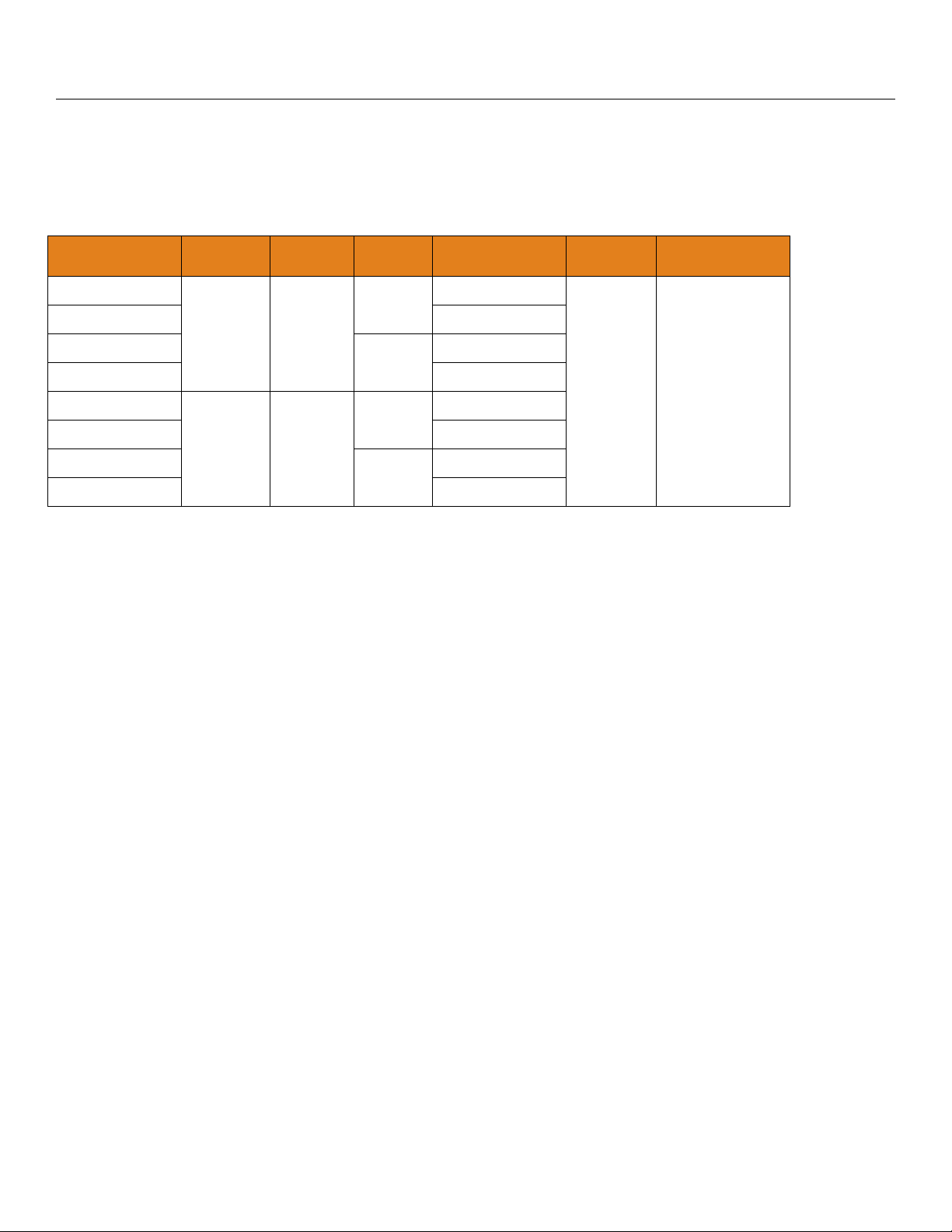
FACTORY SETTINGS
EchoPod® Sensor Height Fill-Height Loop Fail-Safe Output @ Empty
UG03 Series 118.1” (300 cm) 114.1” (290 cm) Hold Last 4mA at Bottom
UG01 Series 59.1” (150 cm) 57.6” (146.2 cm) Hold Last 4mA at Bottom
USER SETTINGS
Fill out the chart below and keep as a record of your configuration.
Tank
Height = Fill-H =
Units
Inches Feet cm Meter
Display
Air Liquid
Safe
22mA 21 mA 20mA Hold Last 4mA
Rev mA
4mA @ Bottom 4mA at Top
Start-up
4mA 12mA 20mA 22mA
Relay(s)
Relay 1 (Blue) Relay 2 (Orange) Relay 3 (Yellow) Relay 4 (Purple)
ON
OFF
TROUBLESHOOTING
PROBLEM SOLUTION
Transmitter indicates a
current of 0 mA:
Transmitter jumps to a
current reading between
19 and 20 mA:
Transmitter indicates a
current over 23 mA:
Check the wiring for an open circuit. An open circuit is the most common issue
with a 0 mA signal.
Check the installation of the transmitter. Bad installation fittings will cause
false signals near the top of the tank, which typically translates to a signal
between 19 and 20 mA. Also look for interference just below the transmitter. If
the transmitter is installed in a metal fitting, switch to a plastic fitting.
Immediately check the wiring for a short circuit. The EchoPod® is current
limited to 22 mA. Anything above 23 mA indicates a short circuit.
| 42 MN310125 Rev A3
Page 43

®
®
Appendix (Continued) Section Seven
TROUBLESHOOTING (CONTINUED)
PROBLEM SOLUTION
Transmitter always jumps
to the LOST condition.
Transmitter output is opposite of the level of liquid.
No Unit Detected in
®
WebCal
.
Internet error. The server
name or address could not
be resolved.
Cannot access some of
the configuration features
®
in WebCal
.
Relay closes, but does not
open again.
Relay chatters on and off
repeatedly.
No unit detected error 1 Both errors can occur when the Display is still plugged in when connecting to
Data page read error 2
Data page read error X
(X is any number greater
than 2)
-1 No device is attached to
the USB Fob, or it is
attached incorrectly.
Please correct and try
again.
-2 Program to loader error
open wires
Check the dimensional configuration (Sensor Height and Fill Height) of
EchoPod
®
. Make sure that the Fill-H setting corresponds to the full level of
liquid (measured from the bottom up) and not the distance from the transmitter
to the liquid (top down).
Check the Output at Empty Setting in WebCal®.
If WebCal
Check that the LI99-2001 Fob is connected to the USB
cannot detect EchoPod® when connected to the computer:
®
port.
Check that all four wires (Red, Black, White and Green) are securely
attached to the Fob.
Check Device Manager and confirm that both drivers (WebCal
®
Configuration & EchoFob) are present.
®
If the above do not work, reinstall the WebCal
software while the computer
is in Safe Mode.
This is a warning indicating that the computer configuring EchoPod® is not
connected to the Internet. Click OK to continue. Flowline recommends being
connecting to the Internet during configuration. But, not being connected to the
®
Internet will not prevent EchoPod
As choices are made in Configuration, WebCal
from being configured.
will begin to eliminate
functions that are not applicable to a configuration. To reset Configuration or
get access to all the features, click on the Clear Screen button.
An inductive kick may be holding the relay closed. If switching 24 VDC, make
sure a diode has been installed to act as a snubber (see Step Nine). Note:
®
EchoPod
uses latching relays. When power is removed to the sensor, the
relays will remain in their last state. Ex: If the relay is energized, when power is
removed, the relay will remain in an energized state.
Most likely the turbulence in the tank is causing the chatter. Increase the
Hysteresis setting in WebCal
®
to eliminate the chatter.
WebCal. Remove the display from its plug and try again.
Make sure display is removed. If issue persists, contact a Flowline
representative.
1. Check the wires connected to the USB Fob as well as to the EchoPod
terminals.
2. Make sure the cable length between the sensor and the computer is less
than 15’ of total cable.
3. Make sure the display was removed from its plug.
4. If this persists, reboot computer in SAFE mode and re-install the WebCal
®
installer program.
Check the wires connected to the USB Fob as well as to the EchoPod
terminals.
MN310125 Rev A3 43 |
Page 44

Warranty, Returns and Limitations Step Eight
WARRANTY
Flowline warrants to the original purchaser of its products that such products will be free from defects in
material and workmanship under normal use and service in accordance with instructions furnished by Flowline
for a period of two years from the date of manufacture of such products. Flowline's obligation under this
warranty is solely and exclusively limited to the repair or replacement, at Flowline's option, of the products or
components, which Flowline's examination determines to its satisfaction to be defective in material or
workmanship within the warranty period. Flowline must be notified pursuant to the instructions below of any
claim under this warranty within thirty (30) days of any claimed lack of conformity of the product. Any product
repaired under this warranty will be warranted only for the remainder of the original warranty period. Any
product provided as a replacement under this warranty will be warranted for the full two years from the date of
manufacture.
RETURNS
Products cannot be returned to Flowline without Flowline's prior authorization. To return a product that is
thought to be defective, go to flowline.com, and submit a customer return (MRA) request form and follow the
instructions therein. All warranty and non-warranty product returns to Flowline must be shipped prepaid and
insured. Flowline will not be responsible for any products lost or damaged in shipment.
LIMITATIONS
This warranty does not apply to products which: 1) are beyond the warranty period or are products for which
the original purchaser does not follow the warranty procedures outlined above; 2) have been subjected to
electrical, mechanical or chemical damage due to improper, accidental or negligent use; 3) have been modified
or altered; 4) anyone other than service personnel authorized by Flowline have attempted to repair; 5) have
been involved in accidents or natural disasters; or 6) are damaged during return shipment to Flowline. Flowline
reserves the right to unilaterally waive this warranty and dispose of any product returned to Flowline where: 1)
there is evidence of a potentially hazardous material present with the product; or 2) the product has remained
unclaimed at Flowline for more than 30 days after Flowline has dutifully requested disposition. This warranty
contains the sole express warranty made by Flowline in connection with its products. ALL IMPLIED
WARRANTIES, INCLUDING WITHOUT LIMITATION, THE WARRANTIES OF MERCHANTABILITY AND
FITNESS FOR A PARTICULAR PURPOSE, ARE EXPRESSLY DISCLAIMED. The remedies of repair or
replacement as stated above are the exclusive remedies for the breach of this warranty. IN NO EVENT SHALL
FLOWLINE BE LIABLE FOR ANY INCIDENTAL OR CONSEQUENTIAL DAMAGES OF ANY KIND
INCLUDING PERSONAL OR REAL PROPERTY OR FOR INJURY TO ANY PERSON. THIS WARRANTY
CONSTITUTES THE FINAL, COMPLETE AND EXCLUSIVE STATEMENT OF WARRANTY TERMS AND NO
PERSON IS AUTHORIZED TO MAKE ANY OTHER WARRANTIES OR REPRESENTATIONS ON BEHALF
OF FLOWLINE. This warranty will be interpreted pursuant to the laws of the State of California. If any portion
of this warranty is held to be invalid or unenforceable for any reason, such finding will not invalidate any other
provision of this warranty.
For complete product documentation, video training, and technical support, go to flowline.com.
For phone support, call 562-598-3015 from 8am to 5pm PST, Mon - Fri.
(Please make sure you have the Part and Serial number available.)
| 44 MN310125 Rev A3
 Loading...