

FlowLine Switch-Tek LV20-1201, Switch-Tek LH-25 Series, Switch-Tek LV-20 Series, Switch-Tek LV20-5201, Switch-Tek LH25-1201 User Manual
Page 1
n
L
u
Swi
t
T
w
es
V
2
0
A
Mini-Float Li
ch-
quid Level S
ek™
itch
V20 & LH
25 Seri
Manual
L
20-1201
LH25-12
LV20-5201
1
Flowli
e, Inc. | 10500 H
mbolt Street, Los
Alamitos, CA 907
0 p 562.598.3015 f 562.431.8507 w flowline.com
MN301310 Rev
Page 2

Introduction / Table of Contents Step One
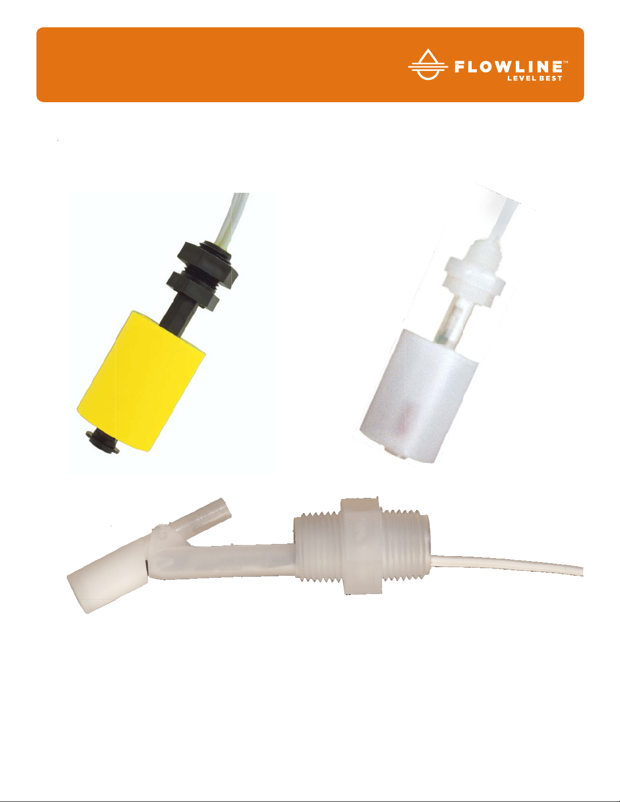
ABOUT SWITCH-TEK™ MINI-FLOAT LEVEL SWITCH
The Mini-Float level switch consists of a float, magnet, reed switch and body/stem with mounting threads.
When the probe is dry, the float rests on the bottom of the stem such that the magnet does not influence the
reed switch. As the probe becomes immersed in liquid, the float becomes buoyant and the magnet elevates
causing the reed switch to change state.
TABLE OF CONTENTS
Specifications: .................................................................................................................. 3
Dimensions: ...................................................................................................................... 4
Safety Precautions: ........................................................................................................... 5
Installation: ....................................................................................................................... 6
General Information: ............................................................................................. 6
Orientation: .......................................................................................................... 7
Electrical: ......................................................................................................................... 8
Voltage: ................................................................................................................. 8
Cable Length: ........................................................................................................ 8
Signal Outputs: ..................................................................................................... 8
Vertical Mini-Float Level Switch: ........................................................................... 8
Horizontal Mini-Float Level Switch: ....................................................................... 9
Contact Protection: ............................................................................................... 9
Wiring: ............................................................................................................................ 10
Wiring to a Flowline Controller: .......................................................................... 10
Maintenance: ................................................................................................................. 11
General: .............................................................................................................. 11
Cleaning Procedure: ........................................................................................... 11
Testing the installation: ....................................................................................... 11
Warranty: ……………… .................................................................................................. 12
2 | MN301310 Rev A
Page 3
Specifications / Dimensions Step Two
Orientation: LV20: ±20˚ from vertical
LH25: ±20˚ from horizontal
Accuracy: ±5mm in water
Repeatability: ±2mm in water
Specific Gravity: LV20: 0.8 minimum
LH25: 0.6 minimum
Contact Type: (1) SPDT reed
Contact Rating: LV20: 120VAC/VDC @ 50 VA
LH25: 120VAC/VDC @ 30 VA
Contact Output: Selectable NO/NC
Temperature Range: LV20: F: -40˚ to 176˚
C: -40˚ to 80˚
LH25: F: -40˚ to 221˚
C: -40˚ to 105˚
Pressure Range: LV20: 10 psi (0.7bar)
LH25: 100 psi (6.9 bar)
Sensor Rating: NEMA 6 / IP68
Sensor Material: LV20-12_1: PP
LV20-52_1: PVDF
LH25-1201: PP
LH25-5201: PVDF
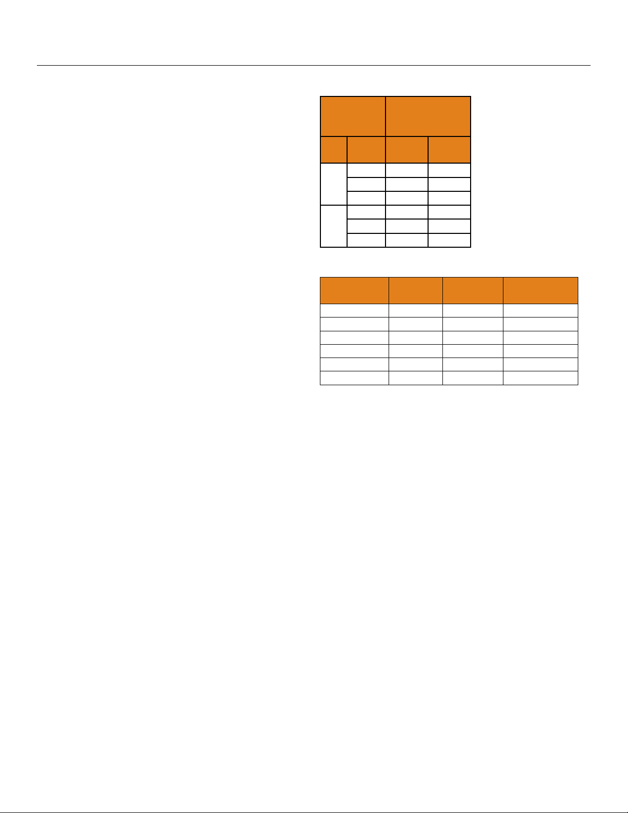
Switch Rating
Reed
Switch
Rating
VA Volts Amps
Maximum
Resistive
Load
Amps
AC
DC
0-50 0.5 0.5
50
120 0.4 0.4
240 0.2 0.2
0-50 0.3 0.28
30
120 0.28 0.07
240 0.14 N/A
Components
Part
Number
Body
Material
Cable
Material
Thread
LV20-1201 PP PVC 1/8” NPT
LV20-1251 PP PVC 1/8” R
LV20-5201 PVDF TFE 1/8” NPT
LV20-5251 PVDF TFE 1/8” R
LH25-1201 PP Polymeric ½” NPT
LH25-5201 PVDF TFE ½” NPT
Wire Jacket Mat’l: LV20-12_1: PVC
LV20-52_1: TFE
LH25-1201: Polymeric
LH25-5201: TFE
Wire Type: 2-conductor, 22-gauge
Wire Length: 2’ (61cm)
Process Mount: LV20: 1/8” NPT (R)
LH25: ½” NPT
Classification: General Purpose
Compliance: CE
MN301310 Rev A 3 |
Page 4
Specifications / Dimensions Step Two
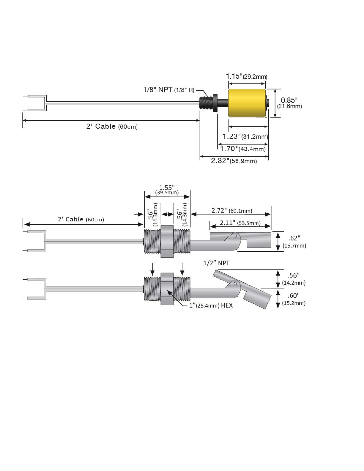
DIMENSIONS
LV20-1201, LV20-1251, LV20-5201, LV20-5251
LH25-1201, LH25-5201
4 | MN301310 Rev A
Page 5

Safety Precautions Step Three
About Manual: PLEASE READ THE ENTIRE MANUAL PRIOR TO INSTALLING OR USING THIS
PRODUCT. This manual includes information on the mini-float level switch, model LV10-_2_1 and LH25_201. Please refer to the part number located on the sensor label to verify the exact model which you have
purchased.
User’s Responsibility for Safety: Flowline manufactures a wide range of liquid level switches and
technologies. While each of the these switches are designed to operate in a wide variety of applications, it
is the user’s responsibility to select a switch model that is appropriate for the application, install it properly,
perform tests of the installed system, and maintain all components. The failure to do so could result in
property damage or serious injury.
Proper Installation and Handling: Because this is an electrically operated device, only properly trained
staff should install and/or repair this product. Use a proper sealant with all installations. Never over tighten
the sensor within the fitting, beyond a maximum of 80 inch-pounds torque. Always check for leaks prior to
system start-up.
Material Compatibility: The LV20 and LH25 series mini-float level switches are available in two wetted
material versions. The LV20-12_1 mini-float vertical switch is made of Polypropylene (PP) with a
Polyvinylchloride (PVC) cable and the LH25-1201 mini-float horizontal switch is made of Polypropylene
(PP) with a Polymeric cable. The LV20-52_1 mini-float vertical switch and the LH25-5201 mini-float
horizontal switch are made of Polyvinylidene Fluoride (PVDF) with a Tetrafluoroethylene (TFE) cable.
Make sure that the switch application is compatible with the liquids. To determine the chemical
compatibility between the sensor and its application liquids, refer to the Compass Corrosion Guide,
available from Compass Publications.
Temperature and Pressure: The LV20 series switch is designed for use in application temperatures up to
80˚C, and for use at pressures up to 10 psi (0.7bar). The LH25 series switch is designed for use in
application temperatures up to 105˚C, and for use at pressures up to 100 psi (6.9bar).
Wiring and Electrical: The supply voltage used for the LV20 switch should never exceed 240 volts AC @
50 VA for the LV20-_2_1. For the LH25 series, the supply voltage should never exceed 240 Volts AC @
30VA. Electrical wiring of the switch should be performed in accordance with all applicable national, state,
and local electrical codes.
Flammable, Explosive and Hazardous Applications: The LV20 and LH25 series mini-float level
switches should not be used within flammable or explosive applications unless properly connected to an
approved control device. In hazardous applications, use redundant measurement and control points, each
having a different sensing technology. Refer to the National Electrical Code (NEC) for all applicable
installation requirements in hazardous locations.
Warning
Avoid installing the mini-float level switches in magnetized metal tanks. Doing so will activate the internal reed
switch.
MN301310 Rev A 5 |
Page 6

Installation Step Four
GENERAL INFORMATION
1. Switches should be installed rigidly so the floats are free to move as the liquid level changes.
2. Switches should be mounted in a tank area free of severe turbulence or protected from such turbulence
by appropriate and adequate slosh shields or barriers such as bypass chamber or stand pipes..
3. Vertical switch stems should be vertical for best results, but satisfactory operation is possible in most
liquids with the stem
4. Horizontal mount switch stems must be mounted with the arrow vertically either up or down depending
on switch operation.
5. Care should be taken that switches are always operated within electrical ratings.
6. The switch state (open or closed) for vertical switches can be changed from normally open when dry to
normally closed when dry or vice versa by removing the float and reversing it on the stem (see Step
Five).
7. The switch state (open or closed) for horizontal switches can be changed from normally open when dry
to normally closed when dry or vice versa by rotating the float 180° across its axis (see Step five).
Top Wall Installation (LV20 series only): FLOWLINE’s LV20
mini-float switch may be installed through the top wall of a tank.
Because the thread of the sensor is very small (1/8”), finding
standard fittings may be difficult. In lieu of standard fittings, one
suggestion is to use a larger pipe, such as ½”. Place a cap or plug
on the end of the pipe and tap a 1/8” thread into the end. Secure
the other end of the pipe to the top of the tank or to a clamp. For
pipes longer than 2’, be sure to extend the cable (splice) so that the
connection is not exposed to the liquid.
≤ 20° angle from vertical.
Through Wall Installation (LH25 series only): FLOWLINE’s LH25 mini-float switch may be installed through
the side wall of a tank. The LH25 series has dual male 1/2" NPT threads for installation from the outside of the
tank in or the inside of the tank out. If the LH25-_201 is installed in the Outside-In method, then the outer
threads may be used for connection to conduit.
Inside-Out
Installation
Outside-In
Installation
6 | MN301310 Rev A
Page 7

Installation Step Four
ORIENTATION
Mounting orientation must be kept vertical for the LV20 series and horizontal for the LH25 series. For proper
orientation, make sure the LV20 series is not off-axis more than 20°. For the LH25 series, make sure the body
of the float is horizontal and not off-axis by more than 20°. In addition, make sure that the float swing is no
more that 20° off-axis.
LV20 Series Off-Axis LH25 Series Off-Axis
LH25 Series Float-Drops LH25 Series Float-Rises
MN301310 Rev A 7 |
Page 8

Electrical Step Five
VOLTAGE
The input voltage to the LV20 / LH25 mini-float switch should never exceed the maximum voltage rating.
FLOWLINE controllers have a built-in 13.5 VDC power supply which provides power to all of FLOWLINE’s
level switches. Alternate controllers and power supplies may also be used with the LV20 / LH25 mini-float
switch.
CABLE LENGTH
Determine the length of cable required between the LV20 series mini-float switch and its point of termination.
Allow enough slack to ensure the easy installation, removal and/or maintenance of the sensor. The cable
length may be extended up to a maximum of 500 feet, using a well insulated, shielded wire.
SIGNAL OUTPUTS (NORMALLY OPEN VS NORMALLY CLOSED)
The LV20 series mini-float switch ships from the factory in the Normally Open (NO) configuration. The normal
state is when the float is resting on the bottom of the stem. An orientation mark will appear on the top of the
float when it is in the NO configuration. To switch the LV20 series from NO to NC configuration, follow the
steps below.
1. Remove the C-clip from the stem.
2. Remove the float and invert the float 180° whereby the orientation mark is now on the bottom.
3. Return the float to the stem.
4. Replace the C-clip.
VERTICAL MINI-FLOAT LEVEL SWITCH (LV20 SERIES ONLY):
Normally Open Operation: Normally Closed Operation:
Orientation mark on the top of the float. In the dry
state, the float rests on the bottom of the stem and the
circuit is open.
As the switch becomes wet, the float becomes
buoyant and circuit closes.
Orientation mark on the bottom of the float. In the dry
state, the float rests on the bottom of the stem and the
circuit is closed.
As the switch becomes wet, the float becomes
buoyant and circuit opens.
8 | MN301310 Rev A
Page 9

Electrical Step Five
HORIZONTAL MINI-FLOAT LEVEL SWITCH (LH25 SERIES ONLY):
Normally Open Operation: Normally Closed Operation:
Position the switch such that the float swings down
when the switch is dry. In the dry state, the float rests
in the lowest position and the circuit is open.
As the switch becomes wet, the float becomes
buoyant and circuit closes.
Position the switch such that the float rests on top of
the switch when the switch is dry. In the dry state, the
float rests on the switch and the circuit is closed.
As the switch becomes wet, the float becomes
buoyant and circuit opens.
CONTACT PROTECTION (REED SWITCH):
When current is interrupted, the inductance of the load generates a high frequency voltage that appears across
the switch contacts. If the voltage is large enough, it can cause arcing. Arcing can cause the contacts to weld
together resulting in unreliable switch performance. It is essential to protect the circuit by suppressing the
voltage to prevent arcing.
To accomplish this, use a diode for DC circuits and a resistor-capacitor network for AC circuits.
DC Contact Protection:
AC Contact Protection:
MN301310 Rev A 9 |
Page 10

Wiring Step Six
WIRING TO A FLOWLINE CONTROLLER
LC40 Series Controller (LC42-1001 Shown) LC10/LC11 Series Controller (LC11-1001 Shown)
NOTE: When using a latching relay, the polarity of both switches must be equivalent. i.e. both switches are
wither wired Normally Open or Normally Closed.
NOTE: Polarity is selected by the orientation of the float.
10 | MN301310 Rev A
Page 11

Maintenance Step Seven
GENERAL
The switch may need to be cleaned periodically to prevent jamming or sticking. The mini-float has no
scheduled maintenance requirement, except to clean off any deposits or scaling from the switch as necessary.
It is the responsibility of the user to determine the appropriate maintenance schedule, based on the specific
characteristics of the application liquid.
CLEANING PROCEDURE
1. Power: Make sure that all power to the switch, controller and/or power supply is completely
disconnected.
2. Switch removal: If necessary, make sure that the tank is drained well below the switch prior to
removal. Carefully, remove the sensor from the installation. Remove the outer screen by pushing on the
screen and turning it slightly to disconnect it from the buoyancy net connector so that the float is
exposed.
3. Cleaning the switch: using a soft bristle brush and mild detergent, carefully wash the switch. Do not
use harsh abrasives such as steel wool or sandpaper that might damage the surface of the sensor. Do
not use incompatible solvents that may damage the sensor’s PP or PVDF plastic body. Take particular
care to remove any scaling from the float body and make sure that it moves freely.
4. Sensor installation: Follow the appropriate steps of installation as outlined in the Installation section of
this manual.
TESTING THE INSTALLATION
1. Power: Turn on power to the controller and/or power supply.
2. Immersing the switch: Immerse the mini-float in its application liquid, by filling the tank up to the
switch
3. Test: With the switch being fluctuated between wet and dry states, the switch indicator light in the
controller should turn on and off. If the controller doesn’t have an input indicator,
4. Point of actuation: Observe the point at which the rising or falling fluid level causes the switch to
change state and adjust the installation of the switch as necessary.
during preliminary testing is to hold a cup filled application liquid up to the switch’s tip.
a. Use a voltmeter with a power supply in series to measure an open or closed circuit.
b. Use an ohmmeter in series to measure an open or closed circuit.
EXAMPLE
Test the LV20 or LH25 series with a Multimeter that is set to read Volts. When wired NO the meter will read 0
volts when dry and full voltage when wet.
MN301310 Rev A 11 |
Page 12

Warranty, Returns and Limitations Step Eight
WARRANTY
Flowline warrants to the original purchaser of its products that such products will be free from defects in
material and workmanship under normal use and service in accordance with instructions furnished by Flowline
for a period of two years from the date of manufacture of such products. Flowline's obligation under this
warranty is solely and exclusively limited to the repair or replacement, at Flowline's option, of the products or
components, which Flowline's examination determines to its satisfaction to be defective in material or
workmanship within the warranty period. Flowline must be notified pursuant to the instructions below of any
claim under this warranty within thirty (30) days of any claimed lack of conformity of the product. Any product
repaired under this warranty will be warranted only for the remainder of the original warranty period. Any
product provided as a replacement under this warranty will be warranted for the full two years from the date of
manufacture.
RETURNS
Products cannot be returned to Flowline without Flowline's prior authorization. To return a product that is
thought to be defective, go to flowline.com, and submit a customer return (MRA) request form and follow the
instructions therein. All warranty and non-warranty product returns to Flowline must be shipped prepaid and
insured. Flowline will not be responsible for any products lost or damaged in shipment.
LIMITATIONS
This warranty does not apply to products which: 1) are beyond the warranty period or are products for which
the original purchaser does not follow the warranty procedures outlined above; 2) have been subjected to
electrical, mechanical or chemical damage due to improper, accidental or negligent use; 3) have been modified
or altered; 4) anyone other than service personnel authorized by Flowline have attempted to repair; 5) have
been involved in accidents or natural disasters; or 6) are damaged during return shipment to Flowline. Flowline
reserves the right to unilaterally waive this warranty and dispose of any product returned to Flowline where: 1)
there is evidence of a potentially hazardous material present with the product; or 2) the product has remained
unclaimed at Flowline for more than 30 days after Flowline has dutifully requested disposition. This warranty
contains the sole express warranty made by Flowline in connection with its products. ALL IMPLIED
WARRANTIES, INCLUDING WITHOUT LIMITATION, THE WARRANTIES OF MERCHANTABILITY AND
FITNESS FOR A PARTICULAR PURPOSE, ARE EXPRESSLY DISCLAIMED. The remedies of repair or
replacement as stated above are the exclusive remedies for the breach of this warranty. IN NO EVENT SHALL
FLOWLINE BE LIABLE FOR ANY INCIDENTAL OR CONSEQUENTIAL DAMAGES OF ANY KIND
INCLUDING PERSONAL OR REAL PROPERTY OR FOR INJURY TO ANY PERSON. THIS WARRANTY
CONSTITUTES THE FINAL, COMPLETE AND EXCLUSIVE STATEMENT OF WARRANTY TERMS AND NO
PERSON IS AUTHORIZED TO MAKE ANY OTHER WARRANTIES OR REPRESENTATIONS ON BEHALF
OF FLOWLINE. This warranty will be interpreted pursuant to the laws of the State of California. If any portion
of this warranty is held to be invalid or unenforceable for any reason, such finding will not invalidate any other
provision of this warranty.
For complete product documentation, video training, and technical support, go to flowline.com.
For phone support, call 562-598-3015 from 8am to 5pm PST, Mon - Fri.
(Please make sure you have the Part and Serial number available.)
12 | MN301310 Rev A
 Loading...