

Page 1
Warranty, Service & Repair
WARRANTY
Flowline warrants to the original purchaser of its products that such
products will be free from defects in material and workmanship under
normal use and service for a period which is equal to the shorter of
one year from the date of purchase of such products or two years from
the date of manufacture of such products.
This warranty covers only those components of the products which
are non-moving and not subject to normal wear. Moreover, products
which are modified or altered, and electrical cables which are cut to
length during installation are not covered by this warranty.
Flowline’s obligation under this warranty is solely and exclusively
limited to the repair or replacement, at Flowline’s option, of the products (or components thereof) which Flowline’s examination proves to
its satisfaction to be defective. FLOWLINE SHALL HAVE NO
OBLIGATION FOR CONSEQUENTIAL DAMAGES TO PERSONAL OR REAL PROPERTY, OR FOR INJURY TO ANYPERSON.
This warranty does not apply to products which have been subject to
electrical or chemical damage due to improper use, accident, negligence, abuse or misuse. Abuse shall be assumed when indicated by
electrical damage to relays, reed switches or other components. The
warranty does not apply to products which are damaged during shipment back to Flowline’s factory or designated service center or are
returned without the original casing on the products. Moreover, this
warranty becomes immediately null and void if anyone other than service personnel authorized by Flowline attempts to repair the defective
products.
Products which are thought to be defective must be shipped prepaid
and insured to Flowline’s factory or a designated service center (the
identity and address of which will be provided upon request) within
30 days of the discovery of the defect. Such defective products must
be accompanied by proof of the date of purchase.
Flowline further reserves the right to unilaterally wave this warranty
and to dispose of any product returned to Flowline where:
a. There is evidence of a potentially hazardous material present
with product.
b. The product has remained unclaimed at Flowline for longer than
30 days after dutifully requesting disposition of the product.
THERE ARE NO WARRANTIES WHICH EXTEND BEYOND
THE DESCRIPTION ON THE FACE OF THIS WARRANTY. This
warranty and the obligations and liabilities of Flowline under it are
exclusive and instead of, and the original purchaser hereby waives, all
other remedies, warranties, guarantees or liabilities, express or
implied. EXCLUDED FROM THIS WARRANTY IS THE IMPLIED
WARRANTY OF FITNESS OF THE PRODUCTS FOR A PARTICULAR PURPOSE OR USE AND THE IMPLIED WARRANTY OF
MERCHANT ABILITY OF THE PRODUCTS.
This warranty may not be extended, altered or varied except by a written instrument signed by a duly-authorized officer of Flowline, Inc.
To register your product with the manufacturer, go to the Flowline
website for on-line registration. The website address is as follows:
www.flowline.com
On-line Warranty Registration can be found under Contact
Flowline on the Navigation Bar along the side of the home page.
If for some reason your product must be returned for factory service, go to
the Flowline website listed above. Online Factory Service can be found
under Contact Flowline on the Navigation Bar along the side of the home
page. Click on Return Authorization to begin the registration process.
You will need the following information at the time of registration:
1. Part Number and full Serial Number from product
2. Name and telephone number of someone who can answer
technical questions related to the product and its application.
3. Return Shipping Address
4. Brief Description of the Symptom
5. Brief Description of the Application
Once you have received a Material Return Authorization number,
ship the product prepaid in its original packing to:
Flowline Factory Service
MRA _____
10500 Humbolt Street
Los Alamitos, CA 90720
To avoid delays in processing your repair, write the MRA on the
shipping label. Please include the information about the malfunction with your product. This information enables our service technicians to process your repair order as quickly as possible.
®
Version 3.2A
© 2007 FLOWLINE Inc.
All rights reserved.
Manual # LV900001-LV10-09/07-M3-2
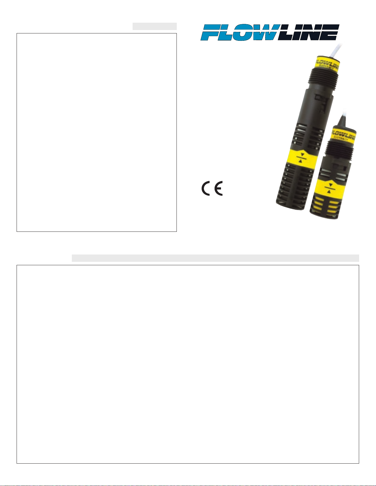
Vertical Buoyancy
Level Switch
LV10 Series
Owner’s Manual
Page 2
Step One
SPECIFICATIONS
Accuracy: ± 2 mm in water
Repeatability: ± 1 mm in water
Extreme orientation: ± 20° from vertical
Specific gravity: .8 minimum
Switch type: -_3_1: Dry contact, SPDT
-_2_1: Dry contact, SPST
Switch voltage: -_3_1: 120 VAC, 120 VDC @ 15 VA
-_2_1: 120 VAC, 120 VDC @ 50 VA
CE rating: 30 Vrms and 42.4 Vpeak or 60 VDC @15 VA
Switch output: Selectable NO or NC states
Temperature range: F: -40° to 176°(C: -40° to 80°)
Pressure range: 25 psi (2 bar) @ 25°C., derated @ 1.667 psi
(.113 bar) per °C. above 25° C.
Probe material: Polypropylene (PP)
Polyvinylidene Fluoride (PVDF)
Probe rating: NEMA 6 / IP68
Mounting threads: 3/4" NPT (3/4” BSP)
Cable type: 10 ft. (3 m), 3-wire, 22 gauge with ground,
shield & PP or PFA jacket
CE compliance: EN 61326 EMC
EN 61010-1 safety
Technology
The vertical buoyancy switch and the vertical float switch both consist of a float, magnet, reed switch and baffle body which dampens
turbulence and eliminates the negative effects of switch chatter. When
the probe is dry, the float rests on the bottom of the baffle body such
that the magnet does not influence the reed switch. As the probe
becomes immersed in liquid, the float becomes buoyant and the magnet elevates causing the reed switch to change state.
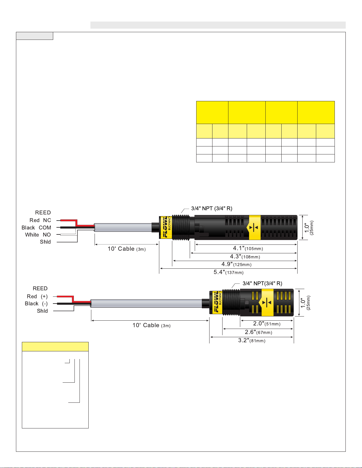
Dimensions
(LV10-1301, LV10-1351, LV10-5301, LV10-5351)
(LV10-1201, LV10-1251, LV10-5201, LV10-5251)
Reed
Switch
Rating
Max.
Resistive
Load
VA15Volts
0-50
120
240
Amps
AC
0.3
0.13
0.06
Amps
DC
0.21
0.09
0.04
Reed
Switch
Rating
Max.
Resistive
Load
VA50Volts
0-50
120
240
Amps
AC
0.5
0.4
0.2
Amps
DC
0.5
0.4
0.2
LV10 - _ _ _ 1
Sensor Material
1 - PP
5 - PVDF
Sensor Length
2 - 3.2" (81 mm)
3 - 5.4" (137 mm)
Mounting Thread
0 - 3/4" NPT
5 - 3/4" BSP
Vertical Buoy ancy & Float
4.1"(105mm)
4.3"(108mm)
1.0"
(25mm)
10' Cable (3m)
4.9"(125mm)
5.4"(137mm)
3/4" NPT (3/4" R)
NC
COM
NO
Shld
Red
Black
White
REED
2.0"(51mm)
1.0"
(25mm)
10' Cable (3m)
2.6"(67mm)
3.2"(81mm)
3/4" NPT(3/4" R)
(+)
(-)
Shld
Red
Black
REED
Page 3

Step Two Step Three
SAFETY PRECAUTIONS INSTALLATION
About this Manual:
PLEASE READ THE ENTIRE MANUAL PRIOR TO
INSTALLING OR USING THIS PRODUCT. This manual
includes information on the vertical buoyancy, model LV10-_3_1,
and vertical float switch, model LV10-_2_1. Please refer to the part
number located on the sensor label to verify the exact model which
you have purchased.
User's Responsibility for Safety:
FLOWLINE manufactures a wide range of liquid level switches
and technologies. While each of these switches are designed to
operate in a wide variety of applications, it is the user's responsibility to select a switch model that is appropriate for the application, install it properly, perform tests of the installed system, and
maintain all components. The failure to do so could result in property damage or serious injury.
Proper Installation and Handling:
Because this is an electrically operated device, only properly
trained staff should install and/or repair this product. Use a proper
sealant with all installations. Never overtighten the sensor within
the fitting, beyond a maximum of 80 inch-pounds torque. Always
check for leaks prior to system start-up.
Material Compatibility:
The LV10 level switch is available in two wetted material versions.
The switch and cable are made of Polypropylene (PP) for the
LV10-1__1. The switch is made of Polyvinylidene Fluoride
(PVDF) and cable is made of Perfluoroalkoxy (PFA) for the LV105__1. Make sure that the switch is compatible with the application
liquids. To determine the chemical compatibility between the sensor and its application liquids, refer to the Compass Corrosion
Guide, available from Compass Publications (858-589-9636).
Temperature and Pressure:
The LV10 series switch is designed for use in application temperatures up to 80 °C, and for use at pressures up to 25 psi (2 bar) @ 25
°C., derated @ 1.667 psi (.113 bar) per °C. above 25 °C.
Wiring and Electrical:
The supply voltage used for the LV10 switch should never exceed
120 volts AC @ 15 VA for the LV10-_3_1 and 120 volts AC @ 50
VA for the LV10-_2_1. For the CE versions, the supply voltage for
the LV10 switch should never exceed 30 Vrms and 42.4 Vpeak or
60 VDC. Electrical wiring of the switch should be performed in
accordance with all applicable national, state, and local codes.
Flammable, Explosive and Hazardous Applications:
The LV10 series switch should not be used within flammable or
explosive applications unless properly connected to a approved
control device. In hazardous applications, use redundant measurement and control points, each having a different sensing technology. Refer to the National Electrical Code (NEC) for all applicable
installation requirements in hazardous locations.
Through Wall Installation:
FLOWLINE’s LV10 switch may be installed through the top wall of
a tank. The sensor has male 3/4" NPT threads and a 3/4" bayonet
adapter on the LV10-_3_1. This enables the user to mount the LV10
using either FLOWLINE's Smart Trak™ or FLOWLINE's Switch
Pak™.
Note: Avoid installing the LV10 in magnetized metal
tanks. Doing so will activate the internal reed switch.
LV10-_3_1 LV10-_3_1
3/4” threads 3/4” bayonet
WARNING
Please observe the difference in wiring and operation between
the LV10-_3_1 and the LV10-_2_1.
Avoid installing the LV10 in tanks in magnetized metal tanks.
Doing so will activate the internal reed switch.
High Level Sensor
Model LV10-_2_1
Switch Pak
LC06
Junction
Box
Low Level Sensor
Model LV10-_3_1
1/2
Coupling
Smart Trak
Page 4

Step Four Step Five
INSTALLATION ELECTRICAL
Orientation:
Mounting orientation must be kept vertical for proper operation. The
vertical buoyancy and float switches are orientated in the vertical
position ±20°.
Voltage:
The input voltage to the LV10 switch should never exceed the maximum voltage rating. FLOWLINE controllers have a built-in 13.5
VDC power supply which provides power to all of FLOWLINE’s
level switches. Alternative controllers and power supplies may also be
used with the LV10 switch.
Cable Length:
Determine the length of cable required between the LV10 series sensor and its point of termination. Allow enough slack to ensure the easy
installation, removal and/or maintenance of the sensor. The cable
length may be extended up to a maximum of 1000 feet, using a wellinsulated, 18 gauge shielded wire.
Wire Stripping:
Using a 10 gauge wire stripper, carefully remove the outer layer of
insulation from the last 1-1/4" of the sensor's cable. Unwrap and discard the exposed foil shield from around the signal wires, leaving the
drain wire attached if desired. With a 20 gauge wire stripper, remove
the last 1/4" of the colored insulation from the signal wires.
Removing Baffle (LV10-_2_1 Only):
The vertical float, model LV10-_2_1, can be installed with out the
protective shield. To do so, remove the shield by twisting it off from
the bayonet adapter. Make sure the C-clip is added to the post to prevent the float from falling off.
Output Selection (LV10-_2_1 Only):
The selection of normally open or normally closed for the
LV10-_2_1 is made by the orientation of the float. The
switch arrives from the factory in the NO position (open circuit when dry). The top of the float is identified by the rough
edges at the end of the float. The smooth end is the bottom
of the float. To change to NC, rotate the float 180°.
+
20
3/4 NPT
FloatShield
C-Clip
?
1"
1/4"
Page 5

Step Six Step Seven
WIRING ORIENTATION
Note: Above wiring is for NO operation (open circuit when switch is dry and closed circuit when
switch is wet). To wire NC (closed circuit when dry
and open circuit when wet), use RED and BLACK
wires for the LV10-_3_1 or reverse the float for the
LV10-_2_1. Use the shield to protect the cable
from electrical noise. Attach to either the Shield
terminal or the ground terminal.
Buoyancy
Buoyancy
Float
Float
All Models:
Wiring to a FLOWLINE Controller
LC10 Series Controller
Vertical Buoyancy Level Switch (LV10-_3_1):
The LV10-_3_1 switch can be wired normally open or normally
closed for your application requirement.
Normally Open:
Use the Black and White wires for operating the LV10-_3_1 in a normally open state. Normally open is defined as the switch being open
when the float is dry and closed when the float becomes submersed.
This operation is typical for indicating a high level.
Normally Closed:
Use the Black and Red wires for operating the LV10-_3_1 in a normally closed state. Normally closed is defined as the switch being
closed when the float is dry and open when the float becomes submersed. This operation is typical for indicating a low level.
LC40 Series Controller
Black
White
Black
Red
White
Power
Supply
Black
White
Power
Supply
Black
Red
Power
Supply
Black
Red
Power
Supply
Black
STANDARD
CONTROLLER
RELAY 1 RELAY 2
POWER
INPUT 1 INPUT 2A INPUT 2B
-
+
-
+
INVERT
DELAY
INVERT
DELAY
LATCH
ON OFF
Black
White
Black
Red
AC
115 VAC
220 VAC
AC
GND
NC
C
NO
DELAY
INVERINVERT +/- +/-
P
R
Input 1A
(+)
(-)
LALATCHTCH
(+)
(-)
B
t 1
u
p
Input 1B
In
Page 6

Step Eight Step Nine
ORIENTATION MAINTENANCE
Vertical Float Level Switch (LV10-_2_1):
The LV10-_2_1 switch can be wired normally open or normally
closed for your application requirement.
Normally Open:
Only use the Black and Red wires with the LV10-_2_1. Orientate the
float upward so that the switch is in the normally open state. Normally
open is defined as the switch being open when the float is dry and
closed when the float becomes submersed. This operation is typical
for indicating a high level.
Normally Closed:
Only use the Black and Red wires with the LV10-_2_1. Orientate the
float downward so that the switch is in the normally closed state.
Normally closed is defined as the switch being closed when the float
is dry and open when the float becomes submersed. This operation is
typical for indicating a low level.
General:
While a filter shroud protects the float from particulate contamination, the switch may need to be cleaned periodically too prevent jamming or sticking. The vertical buoyancy and vertical float has no
scheduled maintenance requirement, except to clean off any deposits
or scaling from the switch as necessary. It is the responsibility of the
user to determine the appropriate maintenance schedule, based on the
specific characteristics of the application liquid.
Cleaning procedure:
1. Power: Make sure that all power to the switch, controller and/or
power supply is completely disconnected.
2. Switch removal:If necessary , make sure that the tank is drained
well below the switch prior to removal. Carefully, remove the sensor from the installation. Remove the outer screen by pushing on
the screen and turning is slightly to disconnect is from the bayonet connector so that the float is exposed.
3. Cleaning the switch:Using a soft bristle brush and mild deter-
gent, carefully wash the switch. Do not use harsh abrasives such
as steel wool or sandpaper, which might damage the surface of the
sensor. Do not use incompatible solvents which may damage the
sensor's PP or PVDF plastic body. Take particular care to remove
any scaling from the float body and make sure that it moves
freely.
4. Sensor installation: Follow the appropriate steps of installa-
tion as outlined in the Installation section of this manual.
Testing the installation:
1. Power:Turn on power to the controller and/or power supply.
2. Immersing the switch: Immerse the sensing tip in its applica-
tion liquid, by filling the tank up to the switches point of actuation. An alternate method of immersing the switch during preliminary testing is to hold a cup filled with application liquid up to
the switch's tip.
3. Test: With the switch being fluctuated between wet and dry
states, the switch indicator light in the controller should turn on
and off. If the controller doesn't have an input indicator, use a voltmeter or ammeter to ensure that the switch produces the correct
signal.
4. Point of actuation: Observe the point at which the rising or
falling fluid level causes the switch to change state, and adjust the
installation of the switch if necessary.
Red
Power
Supply
Black
Red
Power
Supply
Black
Red
Power
Supply
Black
Red
Power
Supply
Black
 Loading...