

FlowLine LU71, LU72, LU73, LU75 Owner's Manual
Warranty, Service & Repair
WARRANTY
Flowline warrants to the original purchaser of its products that such
products will be free from defects in material and workmanship under
normal use and service for a period which is equal to the shorter of
one year from the date of purchase of such products or two years from
the date of manufacture of such products.
This warranty covers only those components of the products which
are non-moving and not subject to normal wear. Moreover, products
which are modified or altered, and electrical cables which are cut to
length during installation are not covered by this warranty.
Flowline’s obligation under this warranty is solely and exclusively
limited to the repair or replacement, at Flowline’s option, of the prod-
ucts (or components thereof) which Flowline’s examination proves to
its satisfaction to be defective. FLOWLINE SHALL HAVE NO
OBLIGATION FOR CONSEQUENTIAL DAMAGES TO PERSON-
AL OR REAL PROPERTY, OR FOR INJURY TO ANYPERSON.
This warranty does not apply to products which have been subject to
electrical or chemical damage due to improper use, accident, negli-
gence, abuse or misuse. Abuse shall be assumed when indicated by
electrical damage to relays, reed switches or other components. The
warranty does not apply to products which are damaged during ship-
ment back to Flowline’s factory or designated service center or are
returned without the original casing on the products. Moreover, this
warranty becomes immediately null and void if anyone other than ser-
vice personnel authorized by Flowline attempts to repair the defective
products.
Products which are thought to be defective must be shipped prepaid
and insured to Flowline’s factory or a designated service center (the
identity and address of which will be provided upon request) within
30 days of the discovery of the defect. Such defective products must
be accompanied by proof of the date of purchase.
Flowline further reserves the right to unilaterally waive this warranty
and to dispose of any product returned to Flowline where:
a. There is evidence of a potentially hazardous material present
with product.
b. The product has remained unclaimed at Flowline for longer than
30 days after dutifully requesting disposition of the product.
THERE ARE NO WARRANTIES WHICH EXTEND BEYOND
THE DESCRIPTION ON THE FACE OF THIS WARRANTY. This
warranty and the obligations and liabilities of Flowline under it are
exclusive and instead of, and the original purchaser hereby waives, all
other remedies, warranties, guarantees or liabilities, express or
implied. EXCLUDED FROM THIS WARRANTY IS THE IMPLIED
WARRANTY OF FITNESS OF THE PRODUCTS FOR A PARTIC-
ULAR PURPOSE OR USE AND THE IMPLIED WARRANTY OF
MERCHANT ABILITY OF THE PRODUCTS.
This warranty may not be extended, altered or varied except by a writ-
ten instrument signed by a duly-authorized officer of Flowline, Inc.
To register your product with the manufacturer, go to the Flowline
website for on-line registration. The website address is as follows:
www.flowline.com
On-line Warranty Registration can be found under Contact Us in
the Navigation Bar along the side of the home page.
If for some reason your product must be returned for factory service, contact Flowline Inc. at (562)598-3015 to receive a Material
Return Authorization number (MRA), providing the following
information:
1. Part Number, Serial Number
2. Name and telephone number of someone who can answer
technical questions related to the product and its application.
3. Return Shipping Address
4. Brief Description of the Symptom
5. Brief Description of the Application
Once you have received a Material Return Authorization number,
ship the product prepaid in its original packing to:
Flowline Factory Service
MRA _____
10500 Humbolt Street
Los Alamitos, CA 90720
To avoid delays in processing your repair, write the MRA on the
shipping label. Please include the information about the malfunction with your product. This information enables our service technicians to process your repair order as quickly as possible.
®
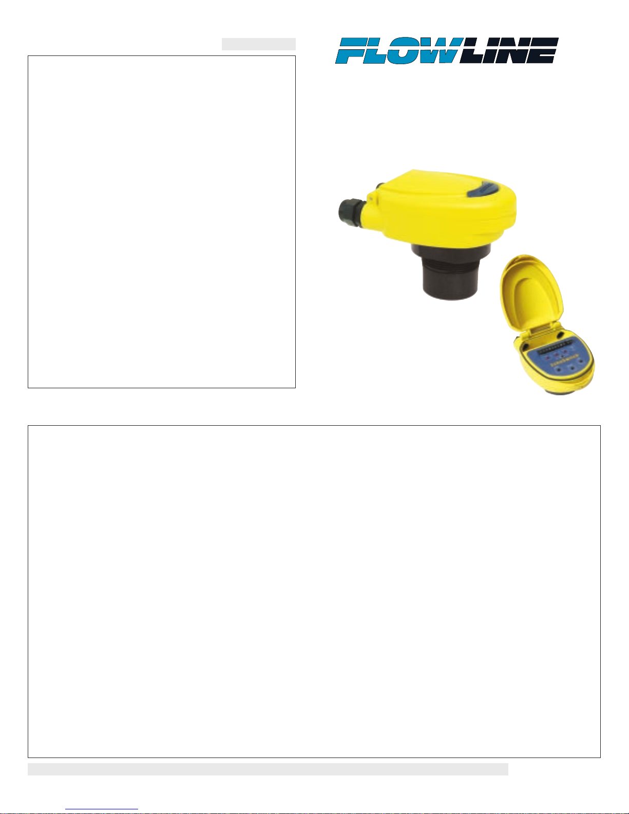
EchoSwitch Multi-Point
Ultrasonic Level Switch
Model LU71/72/73/75
Owner’s Manual
Version 2.1.5
© 2004 FLOWLINE Inc.
All rights reserved.
Manual # LU900014 - 0411-LU72M2_1_5
Step One
SPECIFICATIONS
Range: LU75: 2" to 4'
(5 cm to 1.2m)
LU72: 4" to 9.8'
(10 cm to 3m)
LU71: 4" to 16.4'
(10 cm to 5m)
LU73: 8" to 26.2'
(20 cm to 8m)
Repeatability: 0.25" (6 mm)
Adjustability: Over entire range
Hysteresis: LU72/5: 0.5" (1.2 cm)
(single set point)
LU71/3: 1" (2.5 cm)
(single set point)
Beam width: LU72/5: 2" (5 cm) dia.
LU71/3: 3" (7.6 cm) dia.
Dead band: LU75: 2" (5 cm)
LU71/2: 4" (10 cm)
LU73: 8" (20 cm)
LED indication: Power, relay and echo status
Calibration: Target, push button
Memory: Non-volatile
Supply voltage: 50_5: 95-250 VAC
58_5: 12-28 VDC
Consumption: 50_5: 20 watts max.
58_5: 100 mA @ 24 VDC
Contact type: (3) SPDT relays
Contact rating: 60 VA
Contact logic: Single point: alarm
Two point: latching or
out of bounds alarms
Duplex or Alternation:
(Relays 1 and 2 only)
Contact fail-safety: De-energizes during echo signal loss
Process temp.: F: -4° to 140°
C: -20° to 60°
Temp. comp.: Automatic
Electronics temp.: F: -40° to 160°
C: -40° to 71°
Pressure: 30 psi (2 bar) @ 25° C., derated @
1.667 psi (.113 bar) per °C. above
25° C.
Enclosure rating: NEMA 4X (IP65)
Enclosure vent: Water tight membrane
Encl. material: PC/ABS FR
Trans. material: PVDF Kynar®
Process mount: LU72/5: 1" NPT (1" G)
LU71/3: 2" NPT (2" G)
Mount. gasket: Viton®
Conduit entrance: Dual, 1/2" NPT
Classification: General purpose
CE compliance: EN 61326 EMC
(pending) EN 61010 safety
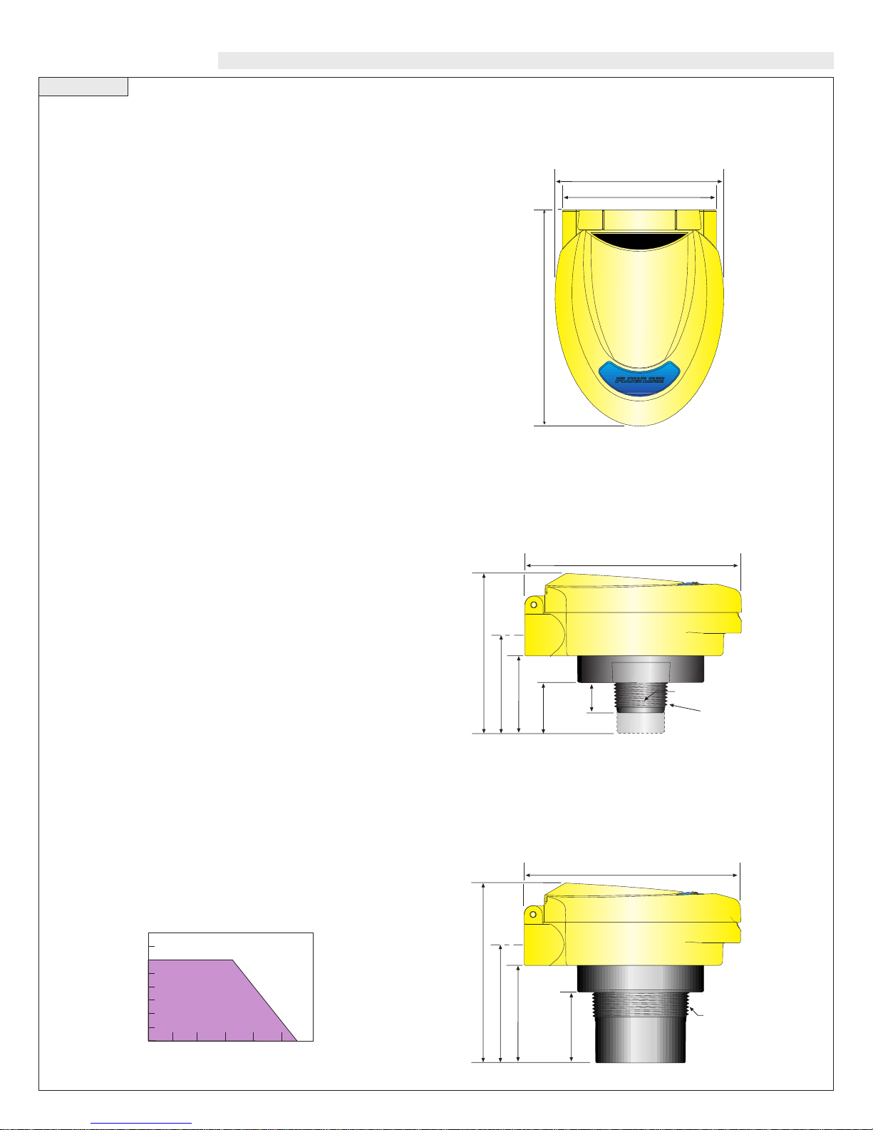
1.2"
(32 mm)
1.9" (49 mm)
3.9" (100 mm)
5.2" (133 mm)
2.4" (62 mm)
1" NPT (1" G)
0.75"
(19 mm)
LU75
LU72
2.5"(63 mm)
4.5" (114 mm)
5.2" (133 mm)
3.0"(76 mm)
2" NPT
(2" G)
1.7"(44 mm)
4.1" (104 mm)
5.2" (133 mm)
3.8" (96 mm)
40
30
20
10
00
-40 -20 00 20 40 60 80
Acceptable
Range
Unacceptable
Range
Temperature/Pressure Derating
Operating Pressure (psi)
Temperature (C¡)
LU71-5_ _5
LU73-5_ _5
Enclosure
Side View
LU75-5 _ _5
LU72-5 _ _5
Enclosure
Side View
LU7_-5 _ _5
Enclosure
Top View
INTRODUCTION TECHNOLOGY
Step Three
A. Application: The general purpose ultrasonic switch provides
non-contact level detection up to 26’ or 8m with 3 relays. Each relay
can be configured on a single set point alarm, two latched set points
for automatic fill or empty, two set points for out of bounds alarms or
three set point (relays 1 and 2 only) alternation / duplexing . The
switch is well suited for a wide range of corrosive, waste and slurry
type media, and is broadly selected for atmospheric day tank, pump
lift station and waste sump applications.
B. Part Number: The part and serial numbers are located on the
wrench flat. Check the part number on the product label and confirm
which of the below model configurations you have purchased:
Part Number
Range Supply Mount
LU75-5005 4’ (1.2m) 95-250 VAC 1” NPT
LU75-5065 4’ (1.2m) 95-250 VAC 1” G
LU75-5805 4’ (1.2m) 12-28 VDC 1” NPT
LU75-5865 4’ (1.2m) 12-28 VDC 1” G
LU72-5005 9.8’ (3m) 95-250 VAC 1” NPT
LU72-5065 9.8’ (3m) 95-250 VAC 1” G
LU72-5805 9.8’ (3m) 12-28 VDC 1” NPT
LU72-5865 9.8’ (3m) 12-28 VDC 1” G
LU71-5005 16.4’ (5m) 95-250 VAC 1” NPT
LU71-5065 16.4’ (5m) 95-250 VAC 1” G
LU71-5805 16.4’ (5m) 12-28 VDC 1” NPT
LU71-5865 16.4’ (5m) 12-28 VDC 1” G
LU73-5005 26.2’ (8m) 95-250 VAC 2” NPT
LU73-5065 26.2’ (8m) 95-250 VAC 2” G
LU73-5805 26.2’ (8m) 12-28 VDC 2” NPT
LU73-5865 26.2’ (8m) 12-28 VDC 2” G
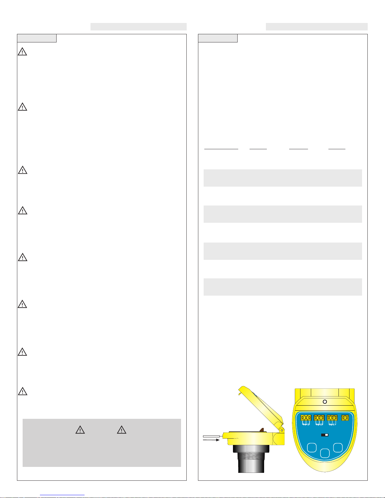
C. NEMA 4X Enclosure: The enclosure has a flip cover with two
1/2” NPT female conduit ports and an internal terminal strip for
wiring. To open the enclosure, you will need a small insertion tool
such as a screwdriver. Insert the tool into the hole located at the
front of the enclosure and gently push on the latching mechanism
to release the cover. Rotate the hinged cover up for 135° access to
the faceplate and terminal strips. Before closing the enclosure,
make sure that the enclosure gasket is properly seated, and
that any conduit fittings, cable connectors or plugs are
installed correctly and sealed.
Step Two
About this Manual: PLEASE READ THE ENTIRE MANU-
AL PRIOR TO INSTALLING OR USING THIS PRODUCT. This
manual includes information on the LU7_-5_ _5 Ultrasonic Level
Switch from FLOWLINE. Please refer to the part number located
on the switch label to verify the exact model configuration which
you have purchased.
User’s Responsibility for Safety: FLOWLINE manufac-
tures a broad range of level sensing technologies. While each of
these sensors is designed to operate in a wide variety of applications, it is the user’s responsibility to select a sensor model that is
appropriate for the application, install it properly, perform tests of
the installed system, and maintain all components. The failure to do
so could result in property damage or serious injury.
Proper Installation and Handling: Only properly trained
staff should install and/or repair this product. Install the switch with
the included Viton gasket and never overtighten the switch within
the fitting. Always check for leaks prior to system start-up.
Wiring and Electrical: A supply voltage of 95-250 VAC is
used to power the LU7_-50 _5 switch, and a supply voltage of 1228 VDC is used to power the LU7_-58_5 switch. Electrical wiring
of the switch should be performed in accordance with all applicable national, state, and local codes.
Material Compatibility: The LU7_-5_ _5 enclosure is made
of a flame retardant Polycarbonate (PC/ABS FR). The transducer is
made of Polyvinylidene Fluoride (PVDF). Make sure that the
model which you have selected is chemically compatible with the
application media.
Enclosure: While the switch housing is liquid-resistant the
LU7_-5 _ _5 is not designed to be operational when immersed. It
should be mounted in such a way that the enclosure and transducer do not come into contact with the application media under normal operational conditions.
Make a Fail-Safe System: Design a fail-safe system that
accommodates the possibility of switch and/or power failure.
FLOWLINE recommends the use of redundant backup systems
and alarms in addition to the primary system.
Flammable, Explosive or Hazardous Applications:
The LU7_-5_ _5 should not be used within classified hazardous
environments.
Warning
Always use the Viton gasket when installing the LU7_-5_ _5
switch, and make sure that all electrical wiring of the switch
is in accordance with applicable codes.
LU7_-5_ _1
Shown
RELAY
1
RELAY2RELAY
3
L
1 L2
POWER
Cal. Run
High Low
Select
EchoSwitch
™
 Loading...