

Page 1
Warranty, Service & Repair
WARRANTY
Flowline warrants to the original purchaser of its products that such
products will be free from defects in material and workmanship under
normal use and service for a period which is equal to the shorter of
one year from the date of purchase of such products or two years from
the date of manufacture of such products.
This warranty covers only those components of the products which
are non-moving and not subject to normal wear. Moreover, products
which are modified or altered, and electrical cables which are cut to
length during installation are not covered by this warranty.
Flowline’s obligation under this warranty is solely and exclusively
limited to the repair or replacement, at Flowline’s option, of the products (or components thereof) which Flowline’s examination proves to
its satisfaction to be defective. FLOWLINE SHALL HAVE NO
OBLIGATION FOR CONSEQUENTIAL DAMAGES TO PERSONAL OR REAL PROPERTY, OR FOR INJURYTO ANY PERSON.
This warranty does not apply to products which have been subject to
electrical or chemical damage due to improper use, accident, negligence, abuse or misuse. Abuse shall be assumed when indicated by
electrical damage to relays, reed switches or other components. The
warranty does not apply to products which are damaged during shipment back to Flowline’s factory or designated service center or are
returned without the original casing on the products. Moreover, this
warranty becomes immediately null and void if anyone other than service personnel authorized by Flowline attempts to repair the defective
products.
Products which are thought to be defective must be shipped prepaid
and insured to Flowline’s factory or a designated service center (the
identity and address of which will be provided upon request) within
30 days of the discovery of the defect. Such defective products must
be accompanied by proof of the date of purchase.
Flowline further reserves the right to unilaterally wave this warranty
and to dispose of any product returned to Flowline where:
a. There is evidence of a potentially hazardous material present
with product.
b. The product has remained unclaimed at Flowline for longer than
30 days after dutifully requesting disposition of the product.
THERE ARE NO WARRANTIES WHICH EXTEND BEYOND
THE DESCRIPTION ON THE FACE OF THIS WARRANTY. This
warranty and the obligations and liabilities of Flowline under it are
exclusive and instead of, and the original purchaser hereby waives, all
other remedies, warranties, guarantees or liabilities, express or
implied. EXCLUDED FROM THIS WARRANTY IS THE IMPLIED
WARRANTY OF FITNESS OF THE PRODUCTS FOR A PARTICULAR PURPOSE OR USE AND THE IMPLIED WARRANTY OF
MERCHANT ABILITY OF THE PRODUCTS.
This warranty may not be extended, altered or varied except by a written instrument signed by a duly-authorized officer of Flowline, Inc.
To register your product with the manufacturer , fill out the enclosed
warranty card and return it immediately to:
Flowline Inc.
10500 Humbolt Street
Los Alamitos, CA 90720.
If for some reason your product must be returned for factory service,
contact Flowline Inc. to receive a Material Return Authorization
number (MRA) first, providing the following information:
1. Part Number, Serial Number
2. Name and telephone number of someone who can answer
technical questions related to the product and its application.
3. Return Shipping Address
4. Brief Description of the Symptom
5. Brief Description of the Application
Once you have received a Material Return Authorization number,
ship the product prepaid in its original packing to:
Flowline Factory Service
MRA _____
10500 Humbolt Street
Los Alamitos, CA 90720
To avoid delays in processing your repair, write the MRA on the
shipping label. Please include the information about the malfunction with your product. This information enables our service technicians to process your repair order as quickly as possible.
®
Version 2.0A
© 1999 FLOWLINE Inc.
All rights reserved.
Manual # LU90000? 5/99
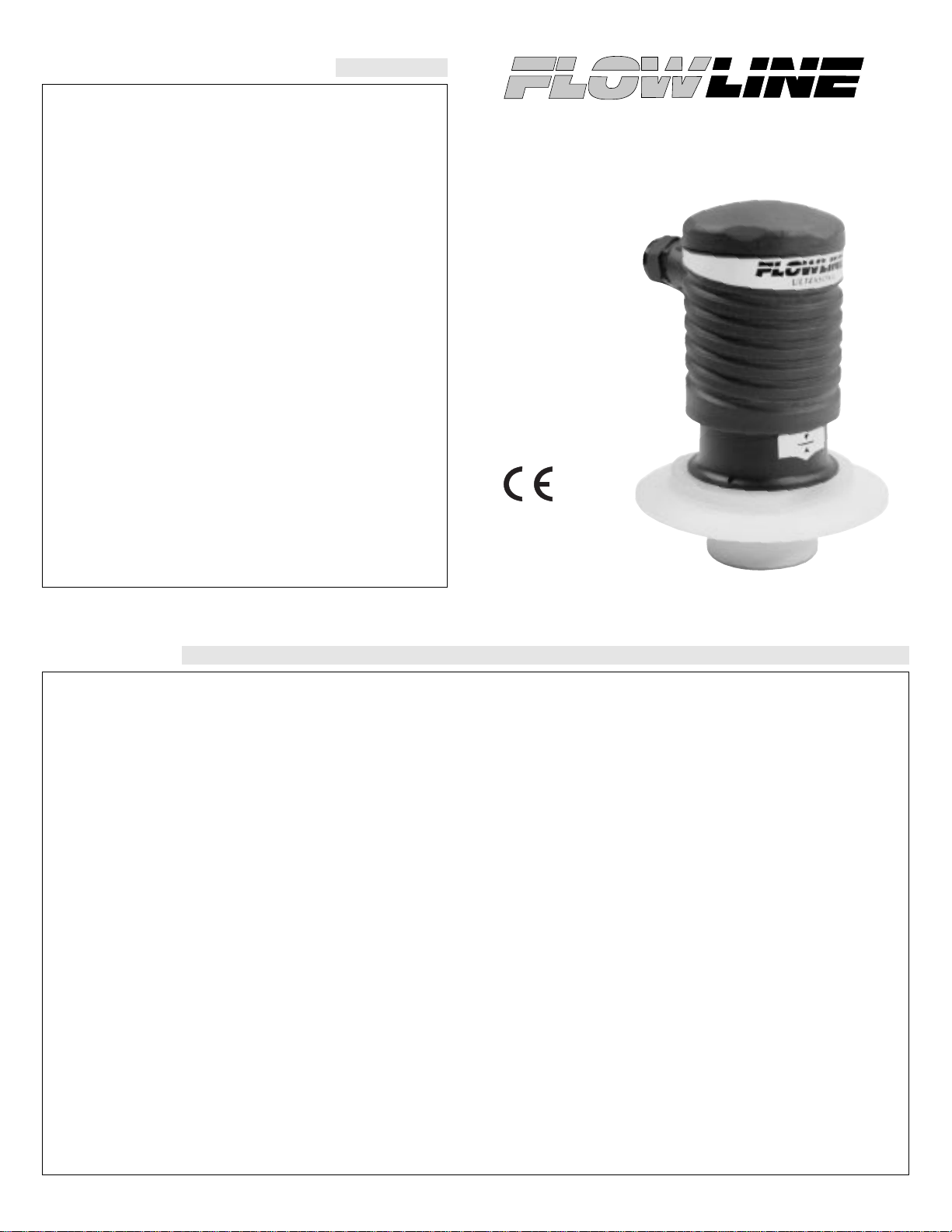
Ultrasonic Level Transmitter
Model LU35
Owner’s Manual
Page 2
Step One
SPECIFICATIONS
Range: 0.5 to 24.5 feet (15 cm to 7.4 m)
Accuracy: ± 0.25% of span in air
Resolution: 0.125” (3 mm)
Frequency: 50 kHz
Pulse rate: 8 pulses per second
Beam width: 8° conical
Blocking distance: 0.5' (15 cm) minimum
Display type: 4 segment LED
Display units: Inch (cm)
Memory: Non-volatile
Supply voltage: 14-36 VDC
Consumption: 200 mA
Current flow: Source / sink
Signal output: 4-20 mA, 14-36 VDC
Signal invert: 4-20 mA/ 20-4 mA
Signal averaging: Fast / slow
Calibration: Push button
Relay type: (1) SPDT
Relay output: 250 VAC, 10A, 1/2 hp
Relay mode: Selectable, NO or NC
Relay indication: ON / OFF status
Contact resistance: 30 milliohm
Fail-safe diagnostics: Relay reverts to safe position
Temperature rating: F: -40º to 140º (C: 100º) max.
Temp. compensation: Automatic over entire range
CIP temperature: F: 230º C: -40º to 60º
Pressure rating: 30 psi (2 bar) @ 25 °C., derated @ 1.667 psi
(.113 bar) per °C. above 25 °C.
Enclosure rating: NEMA 4X (IP65)
Enclosure material: Polypropylene, U.L. 94VO
Transducer material: Natural Polyvinylidene Fluoride (PVDF)
Ferrule connection: 3” (75 mm) or 4” (100 mm)
Conduit connection: 1/2" NPT
CE compliance: EN 50082-2 immunity
EN 55011 emission
EN 61010-1 safety
Technology
An ultrasonic sound wave is pulsed eight times per second from the
base of the transducer. The sound wave reflects against the process
medium below and returns to the transducer. The microprocessor
based electronics measure the time of flight between the sound generation and receipt, and translates this figure into the distance between
the transmitter and process medium below.
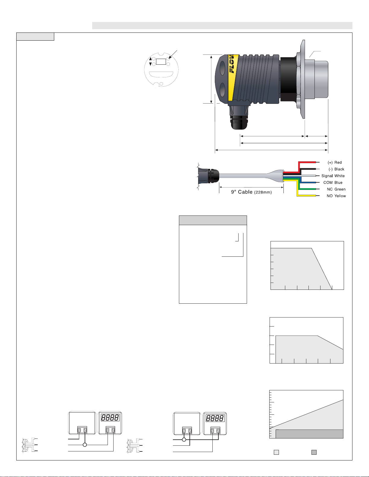
Sinking vs. Sourcing
The LU35 is manufactured in two different outputs, sourcing and sinking. A sourcing transmitter
uses the negative of the power supply as the reference for the entire system. When using a sourcing unit, make sure the negative of the ground is the common for the entire system. A sinking
transmitter uses the positive of the power supply as the reference for the entire system. When
using a sinking unit, make sure the positive of the ground is the common for the entire system.
Holding down the
[MENU] key will
scroll the display in
the following
sequence.
1.6"
(41mm)
5.2" (132mm)
6.6" (168mm)
2.8"
(71mm)
3.6" (92mm)
3" (75mm)
4" (100mm)
LU35 - 5 0 _ _
Process Connection
3 - 3" Ferrule
4 - 4” Ferrule
Switch Output
3 - 4-20 mA, Sourcing
4 - 4-20 mA, Sinking
Ultrasonic Transmitter
+
-
DC Power
Supply
14-36 VDC
200 mA min.
-
+
(+)
(-)
Signal
-Red
-Black
-White
+
-
DC Power
Supply
14-36 VDC
200 mA min.
-
+
(+)
(-)
Signal
-Red
-Black
-White
Temperature/Pressure Derating
35
30
25
20
15
10
05
00
-40 -20 00 20 40 60 80
Operating Pressure (psi)
Temperature (°C)
Unacceptable
Range
Acceptable
Range
Maximum Temperature/Voltage Derating
Continuous 20 mA Curve
100
80
60
40
20
0
12 16 20 24 28 32 36
Operating Voltage (VDC)
Ambient Sensor Temperature (°C)
Unacceptable
Range
Acceptable
Range
2,000
1,500
1,000
500
0
Max. Series Resistance (Ohms)
12 18 24 30 36
Supply Volyage (VDC)
Unacceptable
Range
Acceptable
Range
Flowline 4 or 20 mA
Sensor Electrical Loading Limits
LU35-50_4
LU35-50_3
MENU
SET
RELAY
Echotouch
TM
Ultrasonic Transmitter
L
E
V
E
L
,
E
C
4
,
E
C
2
0
,
R
L
A
Y
,
H
S
E
T
,
L
S
E
T
,
S
A
F
1
/
2
,
F
A
S
T
/
S
L
O
W
,
A
L
I
N
,
O
F
F
/
O
N
,
T
A
N
K
,
(
v
a
l
u
e
)
Sourcing
LU35-50_3
Sinking
LU35-50_4
Page 3

Step Two Step Three
SAFETY PRECAUTIONS DEFINITIONS
About this Manual:
PLEASE READ THE ENTIRE MANUALPRIOR TO INSTALLING
OR USING THIS PRODUCT. This manual includes information on
the continuous ultrasonic level transmitter from FLOWLINE; model
LU35-50__. Please refer to the part number located on the sensor label
to verify the exact model which you have purchased.
User’s Responsibility for Safety:
FLOWLINE manufactures a wide range of liquid level sensors and
technologies. While each of these technologies are designed to
operate in a wide variety of applications, it is the user’s responsibility to select a technology that is appropriate for the application,
install it properly, perform tests of the installed system, and maintain all components. The failure to do so could result in property
damage or serious injury.
Proper Installation and Handling:
Because this is an electrically operated device, only properlytrained staff should install and/or repair this product. Use a proper
sealant with all installations. Never overtighten the transmitter
within the fitting. Always check for leaks prior to system start-up.
Wiring and Electrical:
A supply voltage of 14-36 VDC is used to power the LU35 transmitter. The sensor systems should never exceed a maximum of 36
VDC. Electrical wiring of the sensor should be performed in accordance with all applicable national, state, and local codes.
Temperature and Pressure:
The LU35 is designed for use in application temperatures from -40
°C (-40 °F) to 60 °C (140 °F), and for use at pressures up to 30 psi
(2 bar) @ 25 °C, derated @ 1.667 psi (.113 bar) per °C above 25 °C.
Material Compatibility:
The continuous ultrasonic level transmitter, LU35, is made of two
materials. The enclosure is of Polypropylene (PP) and the transducer is made of Polyvinylidene Fluoride (PVDF). Make sure that
the model which you have selected is chemically compatible with
the application liquids. While the transmitter housing is liquidresistant when installed properly, it is not designed to be immersed.
It should be mounted in such a way that it does not normally come
into contact with fluid.
Flammable, Explosive and Hazardous Applications:
The LU35 level transmitter systems should not be used within
flammable or explosive applications.
Make a Fail-Safe System:
Design a fail-safe system that accommodates the possibility of
transmitter or power failure. In critical applications, FLOWLINE
recommends the use of redundant backup systems and alarms in
addition to the primary system.
EC4: The 4 mA setting for the LU35.
The EC4 is the distance from the bottom of the LU35 to the 4 mA set point.
This setting is measured in either inches or centimeters on the display. The
EC4 setting is typically greater that the
EC20 setting.
EC20: The 20 mA setting for the
LU35. The EC20 is the distance from
the bottom of the LU35 to the 20 mA
set point. This setting is measured in
either inches or centimeters on the display.
RLAY: Indicator for the next two
modes. The 10A relay is latched
between the HSET and LSET points.
HSET & LSET: Sets the high point
and low point for relay activation.
Relay will energize when display value
is greater than the LSET value. Relay
will de-energize when display value is
less than the HSET value. The HSET
value is always less that the LSET
value. To activate the relay from a single point, set HSET and LSET to the
same value.
SAF1/SAF2: The 10A relay inside the LU35 can be used in a failsafe design of your system. When [SAF1] is set, the relay will deenergize when the acoustic return signal is LOST. When [SAF2] is
set, the relay will energize when the acoustic return signal is LOST.
Response times will vary according to the setting of the LU30
([FAST] or [SLOW] modes).
FAST/SLOW: FAST and SLOW sets the reaction time for the
SAF1/2 setting. [FAST] is the typical setting for the LU35 to operate.
The time for the RELAY to default is 30 seconds for [FAST] mode
and 2.5 minutes for [SLOW] mode.
ALIN: Indicates that the unit is in the Alignment mode. Display will
show the return signal strength in dB’s. Used as an indicator for
mechanical alignment of the LU35 and/or signal attenuation. Typical
readings range between 2 and 60 dB’s. For optimum alignment, first
energize the unit and receive a valid return signal. Then select the
ALIN mode and adjust the LU35 until the display is maximized.
ON/OFF: Actual setting for ALIN
mode. The ALIN mode must be turned
[OFF] when alignment is completed.
This mode will not automatically
default back to [LEVL].
TANK: Used as an indication for
[TANK] or maximum range. The
TANK sets the maximum tank height
and will filter out all returns greater
than this value.
(value): Actual TANK setting. The
maximum distance is 288.0 inches.
Warning
The LU35-50_3 is a sourcing transmitter which provides internal 4-20 mAexcitation and should be used with a sinking device.
The LU35-50_4 is a sinking transmitter which requires external
4-20 mA excitation and should be used with a sourcing device.
When installing the LU35, never tighten the transmitter from the
body. Always use the wrench flat located above the threads.
All measurement used for programming the LU35 are made
from the bottom of the transmitter down.
EC20
EC4
20 mA
4 mA
HSET
LSET
De-Energized
Relay
Energized Relay
TANK
Page 4

Step Four Step Five
PROGRAMMING WIRING
EC4:
1. Hold [MENU] key until EC4 appears in display.
2. Release [MENU] key and wait until a value appears. This value is
the current measured level value.
3. If this is acceptable, press [SET] to lock the value as the new EC4
set point. If not, press either the [
s] or [t] keys once and the old
setting for the EC4 will appear.
4. From here, use the [s] or [t] keys to raise or lower the value to
the desired value.
5. Press the [SET] key to enter this value as the new EC4 set point.
EC20:
1. Hold [MENU] key until EC20 appears in display.
2. Release [MENU] key and wait until a value appears. This value is
the current measured level value.
3. If this is acceptable, press [SET] to lock the value as the new
EC20 set point. If not, press either the [s] or [t] keys once and
the old setting for the EC20 will appear.
4. From here, use the [s] or [t] keys to raise or lower the value to
the desired value.
5. Press the [SET] key to enter this value as the new EC20 set point.
HSET/LSET:
1. Hold [MENU] key until HSET or LSET appears in the display.
2. Release [MENU] key wait for the display to change to a number.
3. From here, use the [s] or [t] keys to raise or lower the value to
the desired value.
4. Release all buttons and the value will be entered into memory.
[SET] button does not need to be pressed.
5. Repeat process for the other setting.
SAF1/SAF2:
1. Hold [MENU] key until SAF1 or SAF2 appears in the display.
2. Release [MENU] key and hold [SET] key to toggle between
SAF1 and SAF2.
3. When desired setting is reached, release [SET] key. The last dis-
played setting will be locked into memory. To change, start again
at step 1.
FAST/SLOW:
1. Hold [MENU] key until FAST or SLOW appears in the display.
2. Release [MENU] key and hold [SET] key to toggle between
FAST and SLOW.
3. When desired setting is reached, release [SET] key. The last dis-
played setting will be locked into memory. To change, start again
at step 1.
ALIN:
1. Hold [MENU] key until ALIN appears in the display.
2. Continue to hold [MENU] key until OFF appears in the display.
3. Release [MENU] key and hold [SET] key to toggle from OFF to
ON.
4. Release [SET] key. The LU35 is now in ALIN mode.
5. To exit ALIN mode, repeat steps 1-4 changing from ON to OFF.
TANK:
1. Hold [MENU] key until TANK appears in the display.
2. Continue to hold [MENU] key until a value appears in the display.
This value is the current TANK setting.
3. If this is acceptable, press [SET] to lock the value as the TANK
setting. If not, use the [s] or [t] keys to raise or lower the value
to the desired setting.
4. Press the [SET] key to enter this value as the new TANK setting.
The Echotouch requires 14-36 VDC power with at least 200 mA supply in order to operate.
1. Wiring to a FLOWLINE Continuous Controller (Model LC52):
2. Wiring to a Two-Wire Loop Indicator (Model LU35-5004):
3. Wiring to a Two-Wire Loop Indicator (Model LU35-5003):
4. Wiring to a PLC (LU35-5003):
5. Wiring to a PLC (LU35-5004):
LATCH
ON OFF
PROPORTIONAL
CONTROLLER
PWR
RELAY 1
INVERT
DELAY
RELAY 2
INVERT
DELAY
4 20 OP
EASY CAL
UP DOWN SET
INPUT
0% 100%
OFF SET
SPAN
RLY1
RLY2A
RLY2B
(+)
(-)
Signal
COM
N.C.
N.O.
-Red
-Black
-White
-Blue
-Green
-Yellow
See LC52-1001
Instruction Manual
+
-
DC Power
Supply
14-36 VDC
200 mA min.
-
+
(+)
(-)
Signal
COM
N.C.
N.O.
-Red
-Black
-White
-Blue
-Green
-Yellow
-
+
+
-
DC Power
Supply
14-36 VDC
200 mA min.
(+)
(-)
Signal
COM
N.C.
N.O.
-Red
-Black
-White
-Blue
-Green
-Yellow
+
-
DC Power
Supply
14-36 VDC
200 mA min.
Typical PLC
6
5
4
3
2
1
0
A
250Ω
(+)
(-)
Signal
COM
N.C.
N.O.
-Red
-Black
-White
-Blue
-Green
-Yellow
+
-
DC Power
Supply
14-36 VDC
200 mA min.
Typical PLC
6
5
4
3
2
1
0
A
250Ω
(+)
(-)
Signal
COM
N.C.
N.O.
-Red
-Black
-White
-Blue
-Green
-Yellow
Page 5

Step Six Step Seven
INSTALLATION INSTALLATION
Mounting the LU35 properly is critical to operation. If the LU35 is
installed such that it is recessed in a fitting or flange, follow the criteria listed below. For an I.D. less than 3", do not recess the LU35 more
than 1" for best results.
Factory Settings:
The LU35 sensor is preset at the factory. When powering up the sensor the first time, the factory settings will be active. If at any time in
you need to return to these settings, remove power from the sensor
and wait 10 seconds. Press the [Set] and [Menu] buttons simultaneously while powering up the sensor.
Changing Display Units:
The LU35 comes preset to measure in inches. To change the unit to
display centimeters, remove power to the unit and wait 10 seconds.
Press [s] and [Set] simultaneously while powering up the sensor. The
LU35 will now read in centimeters. To return to inches, remove
power and wait 10 seconds. Press [t] and [Set] simultaneously while
powering up the sensor.
Depth Radius Radius
(Feet) (Inches) (cm)
1' 1.2" 3.1 cm
2' 2.1" 5.2 cm
3' 2.9" 7.3 cm
4' 3.7" 9.5 cm
5' 4.6" 11.6 cm
6' 5.4" 13.7 cm
7' 6.2" 15.9 cm
8' 7.1" 18.0 cm
9' 7.9" 20.1 cm
10' 8.8" 22.3 cm
11' 9.6" 24.4 cm
12' 10.4" 26.5 cm
13' 11.3" 28.7 cm
14' 12.1" 30.8 cm
15' 13.0" 32.9 cm
16' 13.8" 35.1 cm
17' 14.6" 37.2 cm
18' 15.5" 39.3 cm
19' 16.3" 41.3 cm
20' 17.2" 43.6 cm
21' 18.0" 45.7 cm
22' 18.8" 47.8 cm
23' 19.7" 50.0 cm
24' 20.5" 52.1 cm
25' 21.4" 54.2 cm
Maximum Application Range
The maximum range of Echotouch™ is 24.5 feet at 110 dB. Yet a
number of factors can reduce the overall quality of signal return and
shorten the accurate range of the transmitter. To determine the maximum application range of the product, follow the signal return formula against the echo attenuation graph below.
Echo Attenuation Range
ALIGN READING (dB)
10
20
30
40
50
50 100 150 200 250 30000
DISTANCE FROM FACE OF TRANSDUCER (inches)
IDEAL CURVE
10 dB ABSORPTION
20 dB ABSORPTION
2
1
3
4
3: If the actual ALIN = 15dB at D = 50"
4: Maximum Range = 170"
EXAMPLE:
• OPTIMIZE ALIGNMENT
1: Distance from transducer = 50"
2: Highest possible ALIN = 35dB
(under ideal conditions)
Adjust mechanical alignment of unit
to maximize displayed ALIN value
• PREDICT MAXIMUM RANGE
USING ALIGN VALUE
Depth
Inner
Diameter
Depth
Radius
VACUUM
Flange I.D.
(Inches)
3
4
5
6
7
8
3
7
11
15
19
26
Flange I.D.
(Inches)
Avoid
Interference
from side of
tank
Do not install
LU35 at
an angle
Avoid Inter-
ference from
obstructions
in tank
LU35 will not
operate in
vacuum
Warning
When installing the LU35, never tighten the transmitter from the
body. Always use the wrench flat located above the threads.
LEVL
EC 4
EC20
RLAY N/A
HSET
LSET
INCHES (cm)
288" (731.2 cm)
8" (20.3 cm)
5" (12.6 cm)
288" (731.2 cm)
SAF1/2
F/S
ALIN
OFF/ON
TANK
value
SAF1
FAST
N/A
OFF
N/A
288" (731.2 cm)
Page 6

Step Eight Step Nine
INSTALLATION MAINTENANCE
LOST Signal:
A reading of LOST in the display of the LU35 indicates the transmitter is not receiving a valid return signal. If LOST appears, please
check the following troubleshooting items:
1. Beam cone interference such as the side wall, ladders, seams,
rungs or pipes within the LU35's beam cone.
2. Proper installation such that the LU35 is installed level and free
from interference from the installation fitting.
3. Sufficient power being supplied to the LU35. The LU35 requires
14-36 VDC power with a minimum supply of 200 mA.
4. Proper programming of the TANK function. For best results, set
the TANK function as the distance from the bottom of the tank to
the bottom of the transmitter.
5. Make sure that the transmitter is not installed at an angle. Even a
5 degree offset can reduce the signal return strength greatly.
Current is always 4mA or 20 mA:
If the output of the LU35 is always reading 4mA or 20 mA, check the
input values for the LU35. The display of the LU35 reads to the 1/10
of an inch or cm. Adisplay of 1234 is 123.4" and not 1234".
Other Hints:
When checking the EC4 and EC20 values, the first value which
appears after EC4 or EC20 is the current distance from the bottom of
the transmitter to the surface of the liquid. Pressing either the [s] or
[t] buttons will then show the actual value in memory.
General:
The LU35 series sensor itself requires no periodic maintenance
except cleaning as required. It is the responsibility of the user to determine the appropriate maintenance schedule, based on the specific
characteristics of the application liquids.
Cleaning Procedure:
1. Power: Make Sure that all power to the sensor, controller and/or
power supply is completely disconnected.
2. Sensor Removal: In all through-wall installations, make sure
that the tank is drained well below the sensor prior to removal.
Carefully, remove the sensor from the installation.
3. Cleaning the Sensor:Use a soft bristle brush and mild deter-
gent, carefully wash the LU35 series sensor. Do not use harsh
abrasives such as steel wool or sandpaper, which might damage
the surface sensor. Do not use incompatible solvents which may
damage the LU35's Polypropylene or PVDF plastic body.
4. Sensor Installation: Follow the appropriate steps of installa-
tion as outlined in the installation section of this manual.
Internal Relay:
The LU35 series contains a 250 VAC, 10A, 1/2 Hp internal relay. The
relay is actuated by the HSET and LSET settings. While this manual
offers some examples and suggestions to help explain the operation of
the relay, such examples are for information only and are not intended as a complete guide to installing any specific system.
High Level Alarm:
The goal is to make sure the
liquid does not rise above a
certain point. If it does, an
alarm sounds alerting the operator to a high
level condition. Wire the hot lead of the alarm
to the Green NC relay wire. Also make sure the
HSET and LSET settings are programmed correctly. Typically the values are set at the same
distance away from the LU35. In the normal
operation state, the LU35’s relay will
remain energized, keeping the alarm
circuit open. When the alarm level has
been reached, the relay de-energizes
and activaes the alarm. To change to a
low level alarm, re-wire the alarm from
the Green NC wire to the Yellow NO
wire.
Automatic Fill:
The goal is to fill the tank. A
valve is opened (energized)
when a low level is reached
and closed (de-energized) when a high level is
reached. Wire the hot lead of the valve to the
Yellow NO relay wire. Make sure the HSET
and LSET settings are programmed correctly.
Typically the values are set with the HSET as
the valve close and the LSET as the valve open.
A pump or solenoid can be substituted
for the exact same operation. When the
low level is reached, the system will
start to fill the tank. The tank will continue to fill until the level reaches the
high point. The system stops filling
until the low level is reached again. To
change to an automatic empty application, re-wire the system from the
Yellow NO wire the the Green NC wire.
NC
COM
NO
-Green
-Blue
-Yellow
NC
COM
NO
-Green
-Blue
-Yellow
HSET
LSET
De-Energized
Relay
Energized Relay
HSET
LSET
De-Energized
Relay
Energized Relay
 Loading...