

Page 1
®
EchoPulse
Pulse Radar Liquid Level Transmitter
LR15
Application
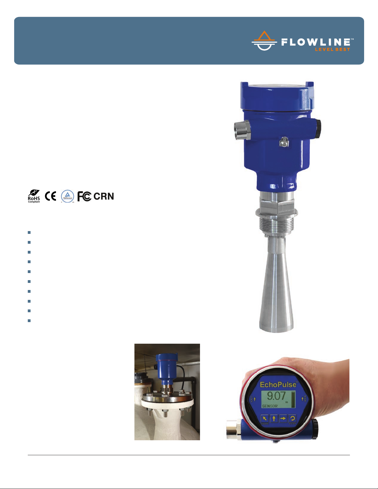
The general purpose 26 GHz. pulse radar transmitter provides
continuous level measurement up to 98.4’ (30m) with a 4-20
mA signal output, and is configured via its integral push button
display module. The non-contact liquid level sensor is intended
for petroleum, water, wastewater and diluted chemical storage
or process applications in above or below grade tanks of any
material. Select this sensor for challenging process conditions
with low or non-corrosive media, light surface foam or agitation,
higher temperature or pressure, condensation or vapor, and
installation in a tank adapter, flange fitting or metal stand-pipe.
Typical applications include bulk storage, tanker truck, process
tank, waste sump and neutralization tanks.
Features
Rugged 316L stainless steel antenna and process mount
Simple configuration via integral push button display module
26 GHz. pulse radar is unaffected by vapor or condensation
12” (30cm) dead band enables utilization of the entire tank
LCD displays level in feet or meters with percent of span bar
Optional display mode indicates the echo signal return curve
Auto-temperature compensation for accurate measurement
Fail-safe diagnostics with selectable signal fail-safe outputs
Recognition, storage and rejection of false echo signal returns
Rugged IP67 aluminum enclosure with polycarbonate window
Success
There are 612k restaurants in the
US that generate waste vegetable
oil. Viscous with floating particulate
and animal fat, waste oil is difficult
to measure. Rendering companies
collect, process and sell waste oil
to secondary markets. Here, a LR15
is flange mounted on a 23’ storage
tank at an oil rendering plant. Its 26
GHz. pulse radar measurement is
unaffected by the process condition.
LR15-0010-20 Shown
© 2016 Flowline | 10500 Humbolt Street, Los Alamitos, CA 90720 USA p 562.598.3015 f 562.431.8507 w flowline.com DS301720 REV B1
Page 2
®
EchoPulse
Pulse Radar Liquid Level Transmitter
LR15
Specifications
Range:
Frequency:
Accuracy:
Dead band:
Beam angle:
Configuration:
Memory:
Display type:
Display units:
Display bar:
Display graph:
Supply voltage:
Max. consumption:
Signal output:
Signal invert:
Signal fail-safe:
Process temp.:
Temp. comp.:
Storage temp.:
Pressure:
Enclosure rating:
Encl. material:
Encl. window mat.:
Conduit entrance:
Antenna material:
Process mount:
Classification:
Certification:
Compliance:
12” to 98.4’ (30cm to 30m)
26 GHz.
± 3mm
12” (30cm)
- 20: 18º
- 30: 12º
- 40: 8º
Push button
Non-volatile
LCD, dot matrix
Feet and meters
Percent of span
Echo signal curve
16-26 VDC
22.5 mA
4-20 mA, two-wire
4-20 mA, 20-4 mA
3.9 mA, 20.5 mA, 22 mA
F: -76º to 302º
C: -60º to 150º
Automatic
F: -40º to 176º
C: -40º to 80º
-14.5 to 150 psi
(-1 to 10 bar)
IP67
Aluminum w/silicone gasket
Polycarbonate
(1) 1/2” NPT connector
(1) M20 x 1.5 plug
316L
1 1/2” NPT
General purpose
cTUVus
FCC
CE, CRN, RoHS
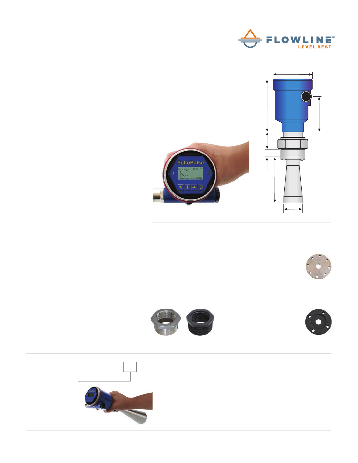
Dimensions
ANTENNA
P/N
X
- 20
2” (48mm)
- 30
3” (78mm)
- 40
4” (98mm)
Echo Signal Return Curve Shown
Y
5.51” (140mm)
8.94” (227mm)
11.34” (288mm)
Fittings
REDUCER BUSHINGS
LM53-2400
2” x 1.5” NPT, PVC, schedule 40
LM53-2800
2” x 1.5” NPT, PVC, schedule 80
LM53-3800
3” x 1.5” NPT, PVC, schedule 80
LM53-2S10
2” x 1.5” NPT, 316 stainless
LM53-2S10
LM53-2800 LM53-3850
97mm
136.5mm
mm
33.5
mm
21.5
140mm
48mm
ANSI FLANGES | SS
LM53-3S50
3” x 1.5” NPT, 316 stainless
LM53-4S50
4” x 1.5” NPT, 316 stainless
LM53-6S50
6” x 1.5” NPT, 316 stainless
ANSI FLANGES | CPVC
LM53-3850
3” x 1.5” NPT, CPVC, schedule 80
LM53-4850
4” x 1.5” NPT, CPVC, schedule 80
LM53-6850
6” x 1.5” NPT, CPVC, schedule 80
83mm
LM53-4S50
Ordering
LR15-0010- 0
ANTENNA SIZE (1) (2 )
2 2” (48mm) horn
3 3” (78mm) horn
4 4” (98mm) horn
© 2016 Flowline | 10500 Humbolt Street, Los Alamitos, CA 90720 USA p 562.598.3015 f 562.431.8507 w flowline.com DS301720 REV B1
NOTES
If you want help in selecting a sensor for your application, please go to our
1)
website and submit a Level Questionnaire. An engineer will review your
requirements and suggest a product solution via email.
To install the radar sensor with a flange or reducer bushing, order the fitting
2)
separately, and follow the antenna preparation instructions in the manual.
 Loading...