

Page 1
Warranty, Service & Repair
WARRANTY
Flowline warrants to the original purchaser of its products that such
products will be free from defects in material and workmanship under
normal use and service for a period which is equal to the shorter of
one year from the date of purchase of such products or two years from
the date of manufacture of such products.
This warranty covers only those components of the products which
are non-moving and not subject to normal wear. Moreover, products
which are modified or altered, and electrical cables which are cut to
length during installation are not covered by this warranty.
FLOWLINE's obligation under this warranty is solely and exclusively
limited to the repair or replacement, at FLOWLINE's option, of the products (or components thereof) which FLOWLINE's examination proves
to its satisfaction to be defective. FLOWLINE SHALL HAVE NO
OBLIGATION FOR CONSEQUENTIAL DAMAGES TO PERSONAL OR REAL PROPERTY, OR FOR INJURYTO ANYPERSON.
This warranty does not apply to products which have been subject to
electrical or chemical damage due to improper use, accident, negligence, abuse or misuse. Abuse shall be assumed when indicated by
electrical damage to relays, reed switches or other components. The
warranty does not apply to products which are damaged during shipment back to FLOWLINE's factory or designated service center or are
returned without the original casing on the products. Moreover, this
warranty becomes immediately null and void if anyone other than service personnel authorized by Flowline attempts to repair the defective
products.
Products which are thought to be defective must be shipped prepaid
and insured to FLOWLINE's factory or a designated service center
(the identity and address of which will be provided upon request)
within 30 days of the discovery of the defect. Such defective products
must be accompanied by proof of the date of purchase.
Flowline further reserves the right to unilaterally wave this warranty
and to dispose of any product returned to Flowline where:
a. There is evidence of a potentially hazardous material present
with product.
b. The product has remained unclaimed at Flowline for longer than
30 days after dutifully requesting disposition of the product.
THERE ARE NO WARRANTIES WHICH EXTEND BEYOND
THE DESCRIPTION ON THE FACE OF THIS WARRANTY. This
warranty and the obligations and liabilities of Flowline under it are
exclusive and instead of, and the original purchaser hereby waives, all
other remedies, warranties, guarantees or liabilities, express or
implied. EXCLUDED FROM THIS W ARRANTYIS THE IMPLIED
WARRANTY OF FITNESS OF THE PRODUCTS FOR APARTICULAR PURPOSE OR USE AND THE IMPLIED WARRANTY OF
MERCHANT ABILITY OF THE PRODUCTS.
This warranty may not be extended, altered or varied except by a written instrument signed by a duly-authorized officer of Flowline, Inc.
®
Version 6.0A
© 2002 FLOWLINE Inc.
All rights reserved.
Manual # LP900002 - LP50-0510-M6_0A
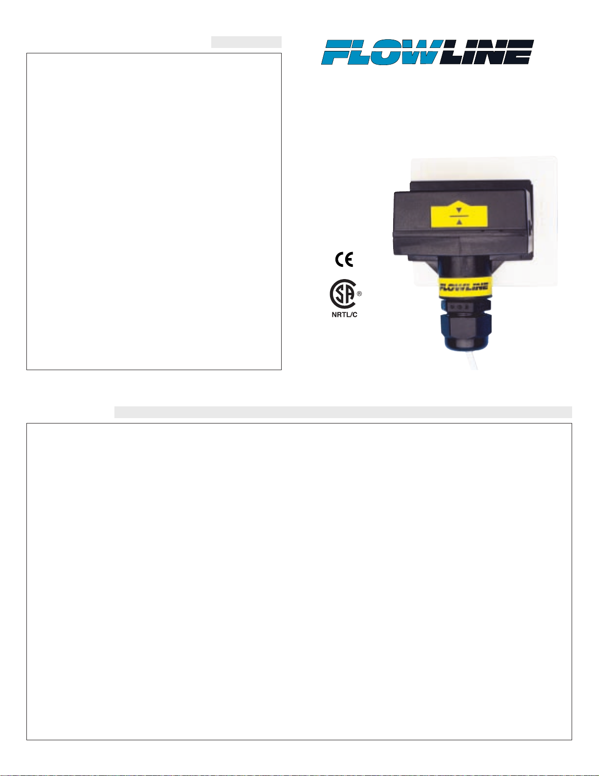
Non-Intrusive RF Capacitance
Level Switch
LP50 Series
Owner’s Manual
To register your product with the manufacturer, go to the Flowline
website for on-line registration. The website address is as follows:
www.flowline.com.
On-line Warranty Registration can be found under Contact Us in
the Navigation Bar along the side of the home page.
If for some reason your product must be returned for factory service, contact Flowline Inc. at (562)598-3015 to receive a Material
Return Authorization number (MRA), providing the following
information:
1. Part Number, Serial Number
2. Name and telephone number of someone who can answer
technical questions related to the product and its application.
3. Return Shipping Address
4. Brief Description of the Symptom
5. Brief Description of the Application
Once you have received a Material Return Authorization number,
ship the product prepaid in its original packing to:
Flowline Factory Service
MRA _____
10500 Humbolt Street
Los Alamitos, CA 90720
To avoid delays in processing your repair, write the MRA on the
shipping label. Please include the information about the malfunction with your product. This information enables our service technicians to process your repair order as quickly as possible.
Page 2
Step One
SPECIFICATIONS
Technology:
The non-intrusive RF capacitance switch detects the presence of liquid or air by measuring the conductive or dielectric values which are present in all materials. An electrical
capacitor is formed between the level switch and the outer
tank wall. As liquid rises and falls against the inner wall, the
capacitance effect is greatly increased and the 1A SPST
relay changes state.
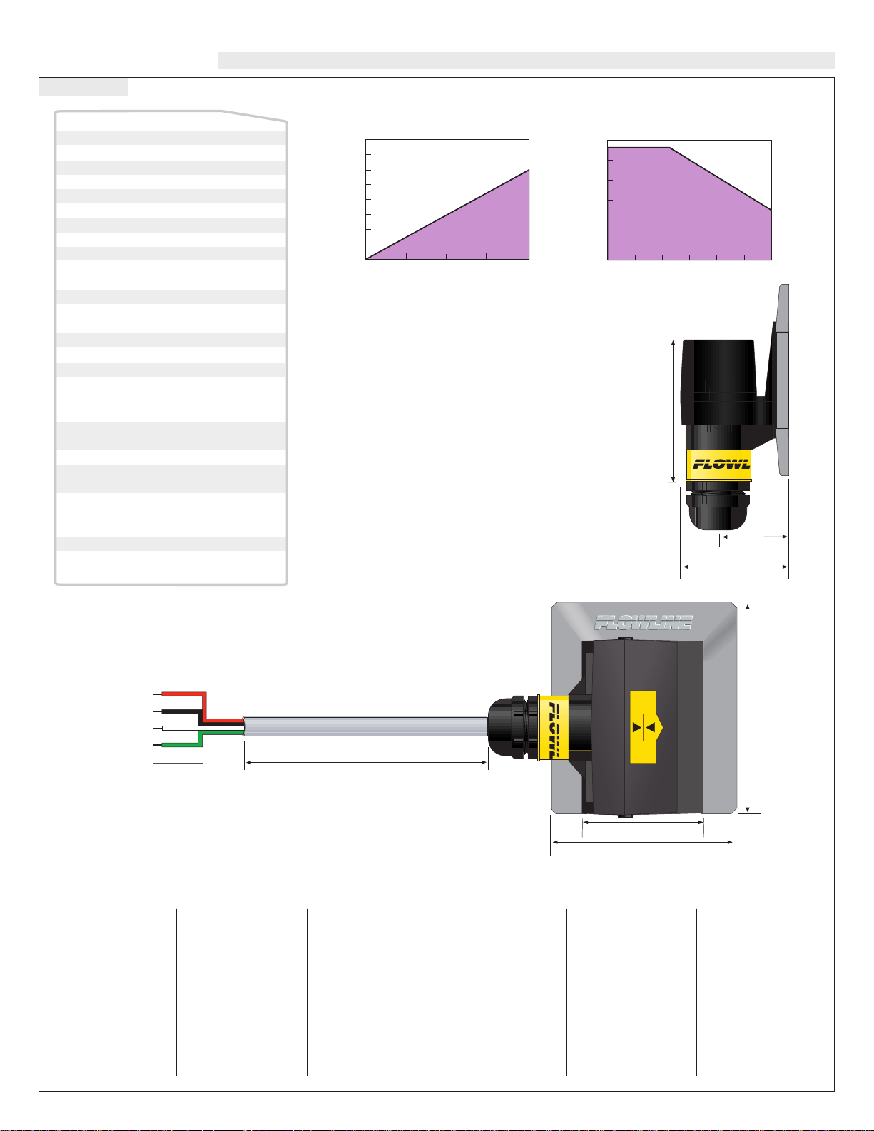
1.7"(44mm)
2.8"(71mm)
3.2"(81mm)
8’ Cable (2.5m)
(+)
(-)
NO/NC
COM
Shld
Red
RELAY
Black
White
Green
1.0"
(25mm)
1.6"(41mm)
2.2"(56mm)
100
80
60
40
20
00
-20
12 16 20 24 28 32 36
Acceptable
Range
Unacceptable
Range
Maximum Tem. / Voltage Derating
Continuous 20 mA Sinking Curve
Ambient Sensor Temperature (¡C)
Operating Voltage (VDC)
1,600
1,400
1,200
1,000
800
600
400
200
0
12 18 24 30 36
Acceptable
Range
Unacceptable
Range
4-20 mA Sensor
Electrical Loading Limits
Max. Series Resistance (Ohms)
Supply Voltage (VDC)
Acetone 21
Acetoaldehyde 22.2
Acetyl methyl hexyl
ketone 28
Alcohol 16 to 31
Ammonia 15 to 25
Acetic acid 4.1 to 6.2
Butyl chloride 9.6
Barium chloride 9 to 11
Benzene 2.3
Benzine 2.3
Barium nitrate 5.6
Bromine 3.1
Chlorobenzene 4.7 to 6
Chlorotoluene 4.7
Chloroform 4.5 to 5.0
Chlorine, liquid 2.0
Carbon tetrachloride 2.2
Cyan 2.6
Cyclohexanemethanol 3.7
D.I. Water 20
Ethyl toluene 2.2
Ethyl alcohol 23
Ethylene glycol 37
Ethylene oxide 14
Ethylene dichloride
11 to 17
Ethylene chloride 10.5
Ethyl acetate 6.4
Ethyl salicylate 8.6
Ethyl stearate 2.9
Ethyl silicote 4.1
Formic acid 59
Ferric oleate 2.6
Freon 2.2
Glycerine 47
Glycol 30
Glycol nitrite 27
Gasoline 2 to 2.2
Hydrochloric acid 4.6
Isobutyric acid 2.7
Isobutyl methyl ketone 13
Jet fuel 1.7
Lead carbonate 18
Lead nitrate 38
Methyl salicylate 9.0
Methanol 33
Methyl alcohol 33 to 38
Margarine,liquid 2.8 to 3.2
Methyl acetate 7.3
N-butyl formate 2.4
Nitrobenzene 26 to 35
Nitrotoluene 25
Naphthalene 2.3 to 2.5
Oils, vegetable 2.5 to 3.5
Oils, mineral 2.3 to 2.4
Oils, petroleum 1.8 to 2.2
Oleic acid 2.5
Propane, liquid 1.8 to 1.9
Potassium nitrate
5.0 to 5.9
Potassium chloride 5.0
Stearic acid 2.3
Toluene 2.4
Trichloroethylene 3.4
Trichloroacetic acid 4.5
Terephthalic acid
1.5 to 1.7
Thinner 3.7
Urea 3.5
Vinyl chloride 2.8 to 6
Vinyl alcohol 1.8 to 2.0
Water, 20°C 80
Water, 100°C 48
Table of Common Dielectric Constants:
NOTE: Liquids with a conductivity value > 100 µ U are fine if coating is not an issue. Liquids with a dielectric constant less than 20 may not be reliably detected by an LP50 series level switch, depending on conditions.
Tank mounting: Non-intrusive
Tank mat. comp.: Non-metallic
Tank wall thick.: < 1" (25 mm)
±
Accuracy:
Repeatability:
Dielectric range: > 10 constants
Conductive range: > 100 micromhos
Supply voltage: 12-36 VDC
Consumption: 25 mA maximum
Contact type: (1) SPST relay
Contact rating: 120 VAC/VDC @ 1A
Contact output: Se le ct ab le N O/ NC
Process temp.: F: -40˚ to 176˚
Enclosure rating: NEMA 4X (IP65)
Enclosure mat.: PS O
Conduit entrance: Si ngl e, 1/2" NPT
Bracket material: 1 005 : PP
Bracket mounting: 3M a dhesive / plastic
Cable jacket mat.: PP
Cable type: 4-conductor, #22 AWG
Cable length: Standard: 10' (3m)
Classification: General purpose
CE compliance: EN 61326 EMC
1 mm in water
±
0.5 mm in water
(CE: 60 VAC/VDC @ 1A)
C: -40˚ to 80˚
50 05 : PVDF
60 05 : PE
th er mal weld
(shielded)
Sp ec ia l or de r: 25'
(7. 6m) or 50' (15.2m)
EN 61010-1 safety
Page 3

Step Two Step Three
SAFETY PRECAUTIONS INTRODUCTION
About this Manual:
PLEASE READ THE ENTIRE MANUAL PRIOR TO
INSTALLING OR USING THIS PRODUCT. This manual
includes information on all models of the Switch-Tek NonIntrusive RF Capacitance level switch from Flowline, LP50-_005.
Please refer to the part number located on the switch label to verify the exact model which you have purchased.
User’s Responsibility for Safety:
Flowline manufactures a wide range of liquid level sensors and technologies. While each of these sensors is designed to operate in a wide
variety of applications, it is the user’s responsibility to select a sensor
model that is appropriate for the application, install it properly, perform tests of the installed system, and maintain all components. The
failure to do so could result in property damage or serious injury.
Proper Installation and Handling:
Because this is an electrically operated device, only properlytrained staff should install and/or repair this product. The adhesive
on the fitting is for temporary installation only. For permanent
installation, the fitting for the sensor should be welded, glassed or
strapped to the tank itself using approved plastic welding techniques. Do not install the LP50 series sensor on a metal tank, or
within 6" of any metal pipe or fitting.
Mounting Bracket:
The LP50 series sensor may be mounted in four different fittings.
A PE bracket (polyethylene, colored white), model LP95-6001.
Other brackets available are LP95-1001 (PP, polypropylene) or
LP95-5001 (PVDF, polyvinylidene fluoride). Make sure that the
fitting which you have selected is compatible with the tank it will
be applied to.
Material Compatibility:
The sensor itself is not designed to be immersed. It should be
mounted in such a way that it does not normally come into contact
with fluid. Its case is made out of Polysulfone (PSO). Refer to an
industry reference such as the Compass Corrosion Guide (available
from Compass Publications, phone 858-589-9636) to ensure that
compounds that may splash onto the controller housing will not
damage it. Such damage is not covered by the warranty.
Wiring and Electrical:
The supply voltage used to power the LP50 series sensor should
never exceed a maximum of 36 volts DC. Electrical wiring of the
sensor should be performed in accordance with all applicable
national, state, and local codes.
Flammable, Explosive and Hazardous Applications:
The LP50-_005 series switch is not rated for use in hazardous locations. Refer to the National Electric Code (NEC) for all applicable
installation requirements in hazardous locations. DO NOT USE
THE LP50-_005 GENERAL PURPOSE SWITCH IN HAZARDOUS LOCATIONS.
About Non-Intrusive RF Capacitance Technology:
FLOWLINE's LP50 series level switch generates a high radio frequency signal from the capacitance electrode on the tank side of each
sensor. Depending on the thickness of the tank wall and the material
of which it is made, there is a particular minimum dielectric value the
electrode measures when there is no liquid on the other side of the
tank wall from the sensor. When liquid is on the other side of the
wall, the dielectric value rises.
As part of installation, a two-step calibration procedure ensures that
the threshold between wet and dry is set at the ideal point for your
particular tank and application fluid, without the use of any external
test equipment. The sensor’s operation and point of actuation may
vary based on the dielectric properties of various application liquids,
tank materials and thicknesses. The LP50 series sensor is intended to
be used with liquids with a dielectric value between 20 and 80. Due
to its user calibration capability it may be able to detect liquids below
a dielectric constant of 20 under certain conditions, but this must be
verified by experimentation.
WARNING
Do not install the LP50 level switch on a metallic tank, or within 6" of any metallic object. Metal will adversely affect the
dielectric sensitivity of the sensor.
FLOWLINE's LP50 series sensors are not recommended for use
with electrically charged application liquids. For most reliable
operation, the liquid being measured may need to be electrically
grounded.
Page 4

Step Four Step Five
INSTALLATION ELECTRICAL
FLOWLINE's LP50 series level switch may be installed anywhere on
a tank wall using the supplied PE, PP, or PVDF fitting that the switch
slides into. The fitting comes with adhesive on the tank side that is
sufficient to hold the sensor in position temporarily while the installation is tested, but for permanent installation the fitting must be
welded, glassed or strapped to the tank. Extra fittings are available
from Flowline, so that the level switch may be moved to different
locations on the tank by sliding it into other fittings.
Attach the fitting to the tank:
1. Determine whether the tank is PP, PE or PVDF. The slide-in fitting shipped with the sensor is determined by the part number. If
necessary, obtain an additional fitting.
2. Determine the mounting location
for the level switch. The point of
actuation (where the sensor will
send a “wet” signal) is most often
at the center of the sensor; however the actual Point of Actuation
(POA) may differ depending on the application liquid and tank
wall characteristics. After positioning the fitting to check clearances, etc., remove the paper protective strips from the adhesive
of the fitting.
3. Press the fitting into place. The adhesive provides a seal between
the sensor and the tank wall, and will hold it in place during testing and installation.
If desired, the sensor may be installed temporarily without welding the fitting to the wall. If several different locations must be
tried before permanent installation, use double-sided foam stick
tape designed for PP, PE or PVDF, for example Arclad type PE6024, CO#7331 (from Adhesive Research Inc., Glen Rock PA
17327) or equivalent.
4. After the sensor has been tested to verify the POA, weld, glass or
strap the fitting to the tank using standard industrial plastic techniques.
Special note for small round tanks:
The fitting may be attached to small, round tanks, as long as the
majority of the fitting is firmly attached to the wall. However,
extreme installations may effect the switches performance.
Mount the sensor in the fitting:
1. Slide the sensor into the fitting.
2. After trimming the sensor wire to length if needed by the installation, thread the sensor wire into a plastic flexible conduit with a
1/2" male fitting. Screw the conduit into the sensor, being careful
not to cross the threads. Do not over tighten the conduit in the
sensor as this may break the fitting. Such damage is not covered
by the warranty. Take care while pulling the wire through conduit
that no excessive tension is placed on the sensor end of the wire,
so that the wire is not broken from the sensor housing.
3. Connect the sensor wire to the controller following the instructions in its manual. See the following Wiring Section for detailed
wiring instructions.
Signal Outputs (Relay switching):
Allows the sensor to switch a small load on or off directly, using an
internal 1 A relay (60 VAC/60 VDC). All models, LP50-_005, use
the relay and features 4 wires (red, black, white and green) and a
shield wire. The NO/NC status is set by the polarity of the voltage
feeding the Red and Black wires. The Green wire is the common for
the relay and the White is the NO or NC, depending on the polarity of
Red and Black.
Normally Open Wiring:
Supply Voltage:
The supply voltage to the Switch-Tek level switch should never exceed
a maximum of 36 VDC. Flowline controllers have a built-in 13.5 VDC
power supply which provides power to all of FLOWLINE's electrically powered sensors. Alternative controllers and power supplies, with a
minimum output of 12 VDC up to a maximum output of 36 VDC, may
also be used with the Switch-Tek level switch.
Required Cable Length:
Determine the length of cable required between the Switch-Tek level
switch and its point of termination. Allow enough slack to ensure the
easy installation, removal and/or maintenance of the sensor. The
cable length may be extended up to a maximum of 1000 feet, using a
well-insulated, 14 to 20 gauge shielded four conductor cable.
Wire Stripping:
Using a 10 gauge wire stripper, carefully remove the outer layer of
insulation from the last 1-1/4" of the sensor's cable. Unwrap and discard the exposed foil shield from around the signal wires, leaving the
drain wire attached if desired. With a 20 gauge wire stripper, remove
the last 1/4" of the colored insulation from the signal wires.
Signal Outputs (Current sensing):
The standard method used by Flowline controllers; this technology uses
only two wires (Red and Black). The sensor draws 5 mAwhen it is dry,
and 19 mAwhen wet. NC/NO status must be set by the controller. The
Green and White wires are not used.
Multimeter
(mA)
Red
Black
Shield
Ground
24 VDC
Power Supply
+
-
+
Multimeter
(Continuity)
Red
Green
Shield
Ground
24 VDC
Power Supply
+
-
-
+
Black
White
Normally Open Wiring:
Switch Bracket Bracket
Part No. Material Part No.
LP50-1005 PP LP95-1001
LP50-5005 PVDF LP95-5001
LP50-6005 PE LP95-6001
Weld
Fitting
Sensor
Screw
1/2" NPT
Connector
Shield
Ground
Black
Red
White
Green
+
24 VDC
Power Supply
-
Multimeter
(Continuity)
+
Page 5

Step Six Step Seven
WIRING WIRING
Wiring to a Flowline Controller
LC40 Series Controller:
STANDARD
CONTROLLER
RE LA Y 1 RE LA Y 2
PO WE R
INP UT 1 INPU T 2A I NPUT 2B
-
+
-
+
INV ERT
DEL AY
INV ERT
DEL AY
LATCH
ON OFF
Black
Shield
White and Green - Not Used
Red
Wiring as a P-Channel or N-Channel output:
The LP50 Series can be substituted for either a P-Channel (PNP,
sourcing) output or a N-Channel (NPN, sinking) output.
Normally Open DC Load as a P-Channel Output:
To wire as a NO P-Channel output, follow the directions below. The
Red wire connects to Positive (+) of the power supply and the Black
wire connects to Negative (-). The Green wire is jumpered to the Red
wire while the White wire is connected to the LOAD. Jumper the
LOAD back to the Negative (-) to complete the circuit.
[Dry Condition]
Sensor
(NO)
RED
GRN
SHLD
WHT
BLK
LOAD
[+]
[-]
[Dry Condition]
Sensor
(NO)
RED
GRN
SHLD
WHT
BLK
LOAD
[+]
[-]
Normally Closed DC Load as a N-Channel Output:
To wire as a NC N-Channel output, follow the directions below. The
Black wire connects to Positive (+) of the power supply and the Red
wire connects to Negative (-). The White wire is jumpered to the Red
wire while the White wire is connected to the LOAD. Jumper the
LOAD back to the Positive (+) to complete the circuit.
Normally Open DC Load as a N-Channel Output:
To wire as a NO N-Channel output, follow the directions below. The
Red wire connects to Positive (+) of the power supply and the Black
wire connects to Negative (-). The White wire is jumpered to the
Black wire while the Green wire is connected to the LOAD. Jumper
the LOAD back to the Positive (+) to complete the circuit.
Normally Closed DC Load as a P-Channel Output:
To wire as a NC P-Channel output, follow the directions below. The
Black wire connects to Positive (+) of the power supply and the Red
wire connects to Negative (-). The Green wire is jumpered to the
Black wire while the White wire is connected to the LOAD. Jumper
the LOAD back to the Negative (-) to complete the circuit.
[Dry Condition]
Sensor
(NO)
RED
GRN
SHLD
WHT
BLK
LOAD
LOAD
OR
[+]
[-]
[Dry Condition]
Sensor
(NC)
BLK
GRN
SHLD
WHT
RED
LOAD
LOAD
OR
[+]
[-]
[AC Power]
[Dry Condition]
Sensor
(NO)
RED
GRN
SHLD
WHT
BLK
LOAD
[+]
[-]
[AC Power]
[Dry Condition]
Sensor
(NC)
BLK
GRN
SHLD
WHT
RED
LOAD
[+]
[-]
Wiring the Relay Output:
The Switch-Tek relay output can be wired as a dry contact to a VDC
or VAC power source. LP50 Series requires 12 - 36 VDC power to
operate the sensor and switch the relay. All illustrations below identify a Dry switch state as the normal position of the relay.
Switching a Normally Open DC Load:
The Red wire connects to Positive (+) of the power supply and the
Black wire connects to Negative (-). The LOAD can be attached to
either the Green or White wires. Complete the circuit by either connecting the Green to (+) VDC power or White to (-) VDC power (see
illustration below).
Switching a Normally Closed DC Load:
The Black wire connects to Positive (+) of the power supply and the
Red wire connects to Negative (-). The LOAD can be attached to
either the Green or White wires. Complete the circuit by either connecting the Green to (+) VDC power or White to (-) VDC power (see
illustration below).
Switching a Normally Open AC Load:
The Red wire connects to Positive (+) of the DC power supply and the
Black wire connects to Negative (-). The LOAD can be attached to
the Green wire and the Hot of the VAC power. Connect the White to
the Neutral of the VAC power (see illustration below).
Switching a Normally Closed AC Load:
The Black wire connects to Positive (+) of the DC power supply and
the Red wire connects to Negative (-). The LOAD can be attached to
the Green wire and the Hot of the VAC power. Connect the White to
the Neutral of the VAC power (see illustration below).
Page 6

Step Eight Step Nine
CALIBRATION CALIBRATION
After it is installed in place, the Switch-Tek must be calibrated by the
user before operation. Everything needed for the procedure is self-contained within the electronics of the LP50 series level switch. Two
dielectric states—full condition and empty condition—are measured by
the Switch-Tek, and then averaged to set the threshold between “wet”
and “dry” at the sensor. The empty state must be at least 6" below the
bottom of the sensor for calibration. The full state must be to the top of
the sensor (not just to the point of actuation) for calibration. The actual application fluid at its intended operating temperature must be used
during calibration. Use the following procedure assumes that the sensor has already been wired to a power supply.
1. Remove the cap from the sensor body by loosening the two
screws located below the sensor. Do not remove the screws from
the sensor. Insert a small screwdriver into the small slot at the
edge of the cap and gently pry upwards.
2. Looking down you will see a small three-position switch and two
trimpots marked Full and Empty. You may start with whatever
state the tank is in.
3. Full state: With
the tank filled to
the top of the sensor, set the switch
to the Full position (right). Make
sure your hands or
any other objects
are not touching
the sensor while calibrating because this will cause a false reading. Using a small nonmetallic screwdriver or alignment tool, turn
trimpot Full until the LED just lights, and no farther. Note the
position. Now turn the trimpot back until the LED turns off. The
ideal setting for the trimpot is midway between these on and off
points.
4. Empty state: With the tank drained to a point no closer than 6
inches below the bottom of the sensor, set the switch to the Empty
position (left). Set the Empty trimpot as in Step 3.
5. After completing calibration, make sure to return the switch to the
center position. Snap the cap back on by pressing down, and tighten the two screws.
Checking the Point of Actuation:
Raise the fluid level to the point
where the sensor sends a “wet”
signal (Input LED will turn
Amber on Flowline controllers). The “dry” signal
should be sent when the fluid
level is lowered (Input LED
will turn Green on Flowline
controllers). The actual Point of
Actuation (POA) depends on many variables, including the thickness of the wall
and the dielectric value of the liquid.
For example, thicker tank walls
can raise the POA while thinner walls could lower the POA.
If the POA needs to be
changed, measure the distance and remount the
sensor in a new location.
Do not attempt to change the Point of Actuation by intentional
miscalibration.
If the sensor does not signal wet and dry reliably, it may be that:
• the dielectric constant of the application fluid is too low
• the tank wall is too thick for the application fluid
• there are static or other electrical charges in the fluid
• metal objects are within 6" of the sensor
• calibration was performed incorrectly
Try the calibration procedure again, after making corrections if possi-
ble. If the full and empty states are too similar dielectrically, it may
not be possible to use a capacitance sensor.
Testing the Sensor:
1. Power: Apply power to sensor, by connecting power to the con-
troller and/or power supply.
2. Full condition: Fill the tank with the application liquid, by filling
the tank up to the sensor’s point of actuation.
3. Test: With the sensor being fluctuated between wet and dry states,
use a multimeter to ensure that the correct signals are being produced by the Switch-Tek level switch, or observe the sensor indicator light in the controller.
4. Point of Actuation: Observe the point at which the rising or
falling fluid level causes the sensor to change state, and move the
installation of the sensor if necessary.
Maintenance:
The LP50 series level switch itself requires no periodic maintenance
except cleaning as required. However, periodically clean any coating
or scaling on the tank wall the sensor is attached to and check the calibration. It is the responsibility of the user to determine the appropriate maintenance schedule, based on the specific characteristics of the
application liquids. In addition, any dripping or condensation
between the sensor and the tank wall fitting may need to be periodically cleaned to maintain accuracy.
Screw Housings
Switch
EMPTY OPERATE FULL
CAL CAL
FULLEMPTY
Full PotEmpty Pot
LED
Operate
Switch
Empty
Pot
Screws
Empty
Cal
LED
Full
Cal
Full
Pot
1"
max.
Full
Calibration
Point
Point of
Actuation
(POA)
Empty
Calibration
Point
6"
min.
Non-conductive
plastic tank wall
 Loading...