

FlowLine LP10 Series Owner's Manual
Warranty Service and Repair ®
To register your product with the manufacturer, fill out the enclosed
warranty card and return it immediately to:
Flowline Inc.
10500 Humbolt Street
Los Alamitos, CA 90720
If for some reason your product must be returned for factory service,
contact your Flowline distributor to receive a material return authorization number first, and provide them with the following information:
1.Part number, serial number
2.Name and telephone number of someone who can answer
questions related to the product and its application
3.Return shipping address
4.Brief description of the symptom
5.Brief description of the application
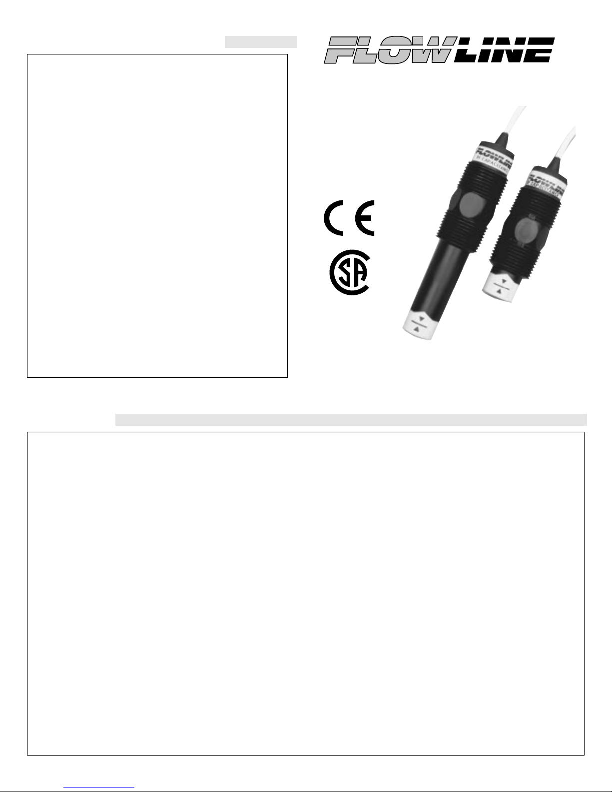
Intrusive RF Capacitance Level Switch
LP10 Series Owner’s Manual
Provided by:
www.KTHSales.com
Once you have received a return authorization number, ship the
product prepaid in its original packing to:
Flowline Factory Service
10500 Humbolt Street
Los Alamitos, CA 90720
Please include any related symptom and application information with
your product. This information enables our service technicians to
process your repair order as quickly as possible.
WARRANTY
Flowline warrants to the original purchaser of its products that such products will be free from defects in material and workmanship under normal use and service for a period which is equal to the shorter of one year
from the date of purchase of such products or two years from the date of
manufacture of such products.
This warranty covers only those components of the products which are
non-moving and not subject to normal wear. Moreover, products which
are modified or altered, and electrical cables which are cut to length
during installation are not covered by this warranty.
Flowline’s obligation under this warranty is solely and exclusively limited to the repair or replacement, at Flowline’s option, of the products
(or components thereof) which Flowline’s examination proves to its satisfaction to be defective. FLOWLINE SHALL HAVE NO OBLIGATION FOR CONSEQUENTIAL DAMAGES TO PERSONAL OR
REAL PROPERTY, OR FOR INJURY TO ANY PERSON.
This warranty does not apply to products which have been subject to
electrical or chemical damage due to improper use, accident, negligence,
abuse or misuse. Abuse shall be assumed when indicated by electrical
damage to relays, reed switches or other components. The warranty does
not apply to products which are damaged during shipment back to
Flowline’s factory or designated service center or are returned without
the original casing on the products. Moreover, this warranty becomes
immediately null and void if anyone other than service personnel authorized by Flowline attempts to repair the defective products.
®
NRTL/C
Version 3.0A
1998 Flowline Inc.
All rights reserved.
Part # LP900001 8/98
Products which are thought to be defective must be shipped prepaid and
insured to Flowline’s factory or a designated service center (the identity
and address of which will be provided upon request) within 30 days of
the discovery of the defect. Such defective products must be accompanied by proof of the date of purchase.
THERE ARE NO WARRANTIES WHICH EXTEND BEYOND THE
DESCRIPTION ON THE FACE OF THIS WARRANTY. This warranty
and the obligations and liabilities of Flowline under it are exclusive and
instead of, and the original purchaser hereby waives, all other remedies,
warranties, guarantees or liabilities, express or implied. EXCLUDED
FROM THIS WARRANTY IS THE IMPLIED WARRANTY OF FITNESS OF THE PRODUCTS FOR A PARTICULAR PURPOSE OR USE
AND THE IMPLIED WARRANTY OF MERCHANT ABILITY OF
THE PRODUCTS.
This warranty may not be extended, altered or varied except by a written
instrument signed by a duly-authorized officer of Flowline, Inc.
If FLOWLINE level transmitters or switches are used for process control
where failure of the transmitter or switch could result in personal injury
or property damage, an independent means such as a redundant FLOWLINE point level switch should be used. Where FLOWLINE level transmitters or switches are used as a part of a pressure vessel or pipe, care
should be taken to independently protect against personal injury or property damage should the FLOWLINE sensor fail or be mishandled. Contact FLOWLINE or your local distributor for additional information.
SPECIFICATIONS
Step One
Accuracy: ±1 mm in water
Repeatability: ± .5 mm in water
Dielectric range: > 20 constants
Conductive range: > 100 micromhos
Supply voltage: 12 - 36 VDC
Consumption: Relay: 25 mA
Relay rating: 60 VDC/VAC @ 1A
FET rating: 36 VDC max. @ 100 mA max.
Switch output: Selectable NO or NC
Temperature range: F: -40° to 194°
Pressure range: 150 psi (10 bar) @ 25 °C., derated @ 1.667
Sensor material:
Sensor rating: NEMA 6 (IP68)
Mounting threads: Short: 3/4" NPT (3/4" BSP)
Mounting gasket: Viton (3/4"), metric only
Cable type: 8 ft. (2.5 m), 4-wire (relay) or 3-wire (FET),
CSA approval: Class I, Groups A, B, C & D;
CSA entity parameters: V
Certificate number: LR 79326-4
CE compliance: EN 50082-2 immunity
LP10 - _ _ _ _
Sensor Material
1 - PP
2 - PFA
Sensor Length
3 - Short
4 - Long
Mounting Thread
0 - 3/4" NPT
2 - 3/4" G
Switch Output
0 - Intrinsically Safe
2 - FET, N-Channel
3 - FET, P-Channel
5 - Relay
Dimensions
FET: 5mA, ± 1mA (dry)
19 mA, ± 1mA (wet)
C: -40° to 90°
psi (0.113 bar) per °C. above 25 °C.
Polypropylene (PP) or Perfluoroalkoxy (PFA)
Long: 3/4" NPT (3/4" G)
22 gauge with shield & PP or PFA jacket
Class II, Groups E, F & F; Class III
= 32 VDC
max
I
= 0.5 A
max
C
= 0 µF
i
L
= 0 mH
i
EN 55011 emission
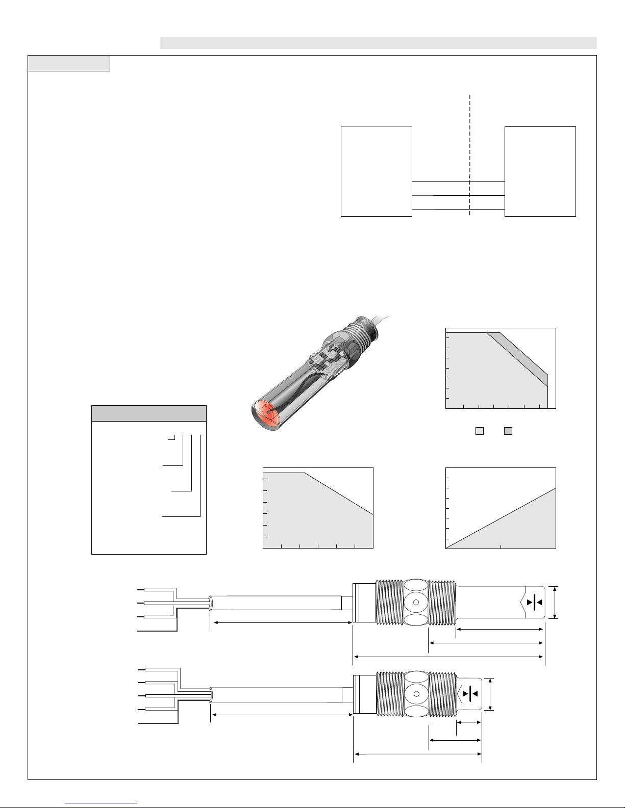
Capacitance Switch
Maximum Temperature / Voltage Derating
100
80
60
40
20
00
-20
-40
Ambient Sensor Temperature (°C)
Intrinsically Safe Control Drawing
NON-HAZARDOUS LOCATION
Associated
Equipement
(see notes 2 and 5)
Notes:
LP50 series sensor suitable for Class I, Groups A, B, C, and
1.
D locations only.
CSA certified associated equipment with entity parameters.
2.
Vmax ≥ Voc, Imax ≥ Isc, Ci + Ccable ≤ Ca, Li + Lcable ≤ La.
3.
Installation should be in accordance with CEC Part I, or
4.
NFPA 70.
Associated equipment must be installed per manufacturers
5.
instructions
Continuous 20 mA Sinking Curve
Unacceptable
Range
Acceptable
Range
12 16 20 24 28 32 36
Operating Voltage (VDC)
HAZARDOUS LOCATION
Class I, Groups A,B, C, and D
Class II, Groups E, F, and G
Red Wire
Black Wire
Shield
Sensor Drawing: LSD1
Rev. A 7-21-95
Temperature / Pressure Derating
160
140
120
100
80
60
40
20
Operating Pressure (psi)
00
1,600
1,400
1,200
1,000
800
600
400
200
0
Max. Series Resistance (Ohms)
Acceptable
Range
-40 -20 00 20 40 60 80 100
12 24 36
Temperature (°C)
PP PFA
4-20 mA Sensor
Electrical Loading Limits
Unacceptable
Range
Supply Voltage (VDC)
Class III, (see note 1)
Sensor Models
LP10
LP50
LU10
LO10
Entity Parameters
V
max = 32V
Imax = 0.5A
Ci ≈ 0
Li ≈ 0
Unacceptable
Range
Acceptable
Range
(+)
(-)
FET
FET
Black
White
Wiring
Red
shld
Relay
Wiring
Red
Black
White
Green
(+)
(-)
NO/NC
COM
shld
8' Cable (2.5 m)
8' Cable
(2.5 m)
3.0"
4.5" (114 mm)
(76 mm)
1.3"
2.8" (70 mm)
0.7"
(19 mm)
(32 mm)
2.1" (54 mm)
0.7"
(19 mm)
0.7"
(19 mm)
*All dimensions
are nominal
 Loading...