

Page 1
Switch-Tek™
Powered Liquid Level Switches
LZ12, LU10, LP15 & LO10 Series Manual
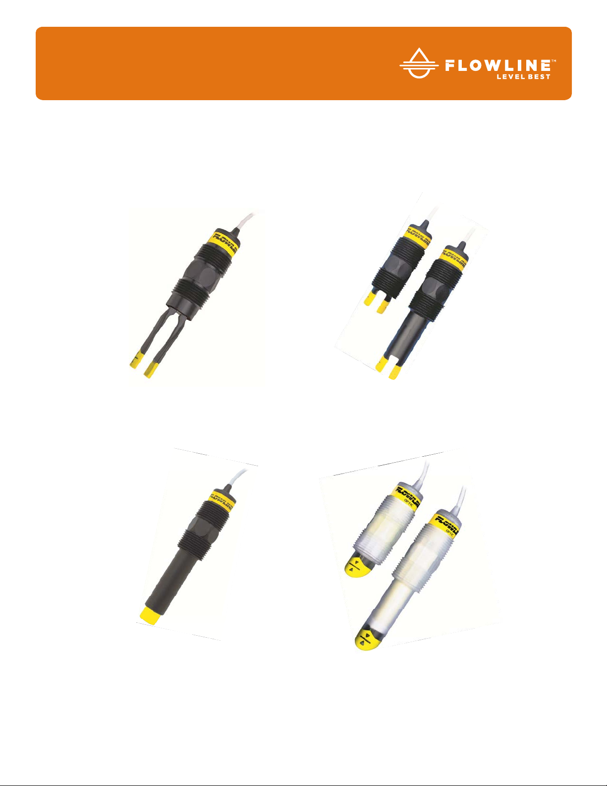
LZ12 Series
LU10 Series
LP15 Series
LO10 Series
Flowline, Inc. | 10500 Humbolt Street, Los Alamitos, CA 90720 p 562.598.3015 f 562.431.8507 w flowline.com MN301370 Rev B2
Page 2

Introduction / Table of Contents Step One
ABOUT SWITCH-TEK™ POWERED LEVEL SWITCHES
This manual contains information on all four models of Flowline Switch-Tek
(LZ12 series), Ultrasonic (LU10 series), Optic Leak (LO10 series) and SuperGuard Capacitance (LP15 series).
The switches all feature two outputs: 1) a 4 or 20 mA current switch and 2) a 60VA SPST dry contact relay. All
four series are manufactured with thermoplastics, including the cable, making them submersible in design and
ideal for corrosive applications. Package the switches with either Flowline controllers (LC10 or LC40 series) or
interface directly to another controller or PLC.
TABLE OF CONTENTS
Specifications: .................................................................................................................. 3
Sensor Information: ......................................................................................................... 4
Vibration Level Switch (LZ12 Series): .................................................................. 4
Maintenance Alarm: .................................................................................. 5
Ultrasonic Level Switch (LU10 Series): ................................................................ 6
Optic Leak Detection Switch (LO10 Series): ........................................................ 7
Capacitance Level Switch (LP15 Series): ............................................................ 8
Safety Precautions: .......................................................................................................... 9
Make a Fail-Safe System:: ................................................................................... 9
Installation: ..................................................................................................................... 10
Through Wall Installation: .................................................................................. 10
Top Wall Installation: .......................................................................................... 10
Electrical: ....................................................................................................................... 11
Wiring: ............................................................................................................................ 12
Wiring to a Flowline Controller: ...................................................................................... 12
Switching Inductive Loads: ................................................................................ 12
Wiring the Relay Output: .................................................................................... 13
Intrinsically Safe Control Drawings (LU10 Series Only): ............................... 14-15
Wiring as a P-Channel or N-Channel Output: .................................................... 16
Maintenance: ................................................................................................................ 17
Cleaning Procedure: .......................................................................................... 17
LZ12 Maintenance Alarm: .................................................................................. 17
Testing the Installation: ...................................................................................... 18
Warranty, Returns & Limitations: ................................................................................... 19
™
powered level switches; Vibration
| 2 MN301370 Rev B2
Page 3
Specifications - Common Step Two
COMMON SPECIFICATIONS
Orientation: Universal
Accuracy: ± 1 mm in water
Repeatability: ± 0.5 mm in water
Supply voltage: 12-36 VDC
12-30 VDC (LZ12 Only)
Consumption: 25 mA maximum
Contact type: (1) SPST relay
Contact rating: 60VA (125 VAC max / 1A
max)
Contact output: Selectable NO/NC
Process temp.: F: -40° to 176°
C: -40° to 80°
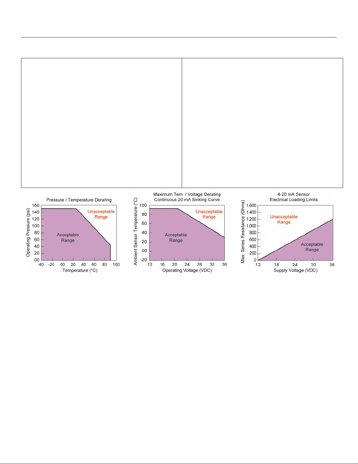
Pressure: 150 psi (10 bar) @ 25 °C.,
derated @ 1.667 psi (.113 bar)
per °C. above 25° C.
Sensor rating: NEMA 6 (IP68)
NEMA 4X (IP65) - LU10-2_ _5
series only
Cable type: 4-conductor, #22 AWG
(shielded)
Cable length: 10' (3m) - Standard
25' (7.6m) or 50' (15.2m) -
Special
Process mount: 3/4" NPT (3/4" G / R)
Mount. gasket: Viton® (G / R version only)
Classification: General purpose
CE compliance: EN 61326 EMC / EN 61010-1
safety
MN301370 Rev B2 3 |
Page 4
Sensor Information - Vibration Step Three
VIBRATION LEVEL SWITCH (LZ12 SERIES)
The Vibration switch operates at a nominal frequency of 400 Hz. As the switch becomes immersed in a liquid
or slurry, a corresponding frequency shift occurs. When the measured frequency shift reaches the set point
value, the switch changes state indicating the presence of a liquid or slurry medium. For optimum performance
and proactive maintenance, the sensor automatically adjusts for coating, and if necessary, outputs a
preventative maintenance alarm.
Do not squeeze the forks together. Doing so could damage or break the sensor and void the warranty.
When powering up the LZ12, the start-up procedure requires the switch to cycle through a wet condition for 1/2
second in order to determine an initial resonance.
LZ12 SPECIFICATIONS
Sensor material: Ryton® (glass fill)
Viton® cable grommet
Process temp.: F: -40° to 176°
C: -40° to 80°
CONFIGURATIONS
Maint. alarm: NPN transistor, 10 mA max.
Cable jacket mat’l: PP
Cable type: 5-conductor, #24 AWG
(shielded)
Thread
Part
Number
Length
Material
(cable)
cable
side
X
sensor
side
LZ12-1405 Ryton Polypropylene ¾” NPT x ¾” NPT
LZ12-1425 Ryton Polypropylene ¾” R x ¾”G
| 4 MN301370 Rev B2
Page 5
Sensor Information - Vibration Step Three
MAINTENANCE ALARM (LZ12 VIBRATION ONLY)
For optimum performance and proactive maintenance, the sensor automatically adjusts for coating, and if
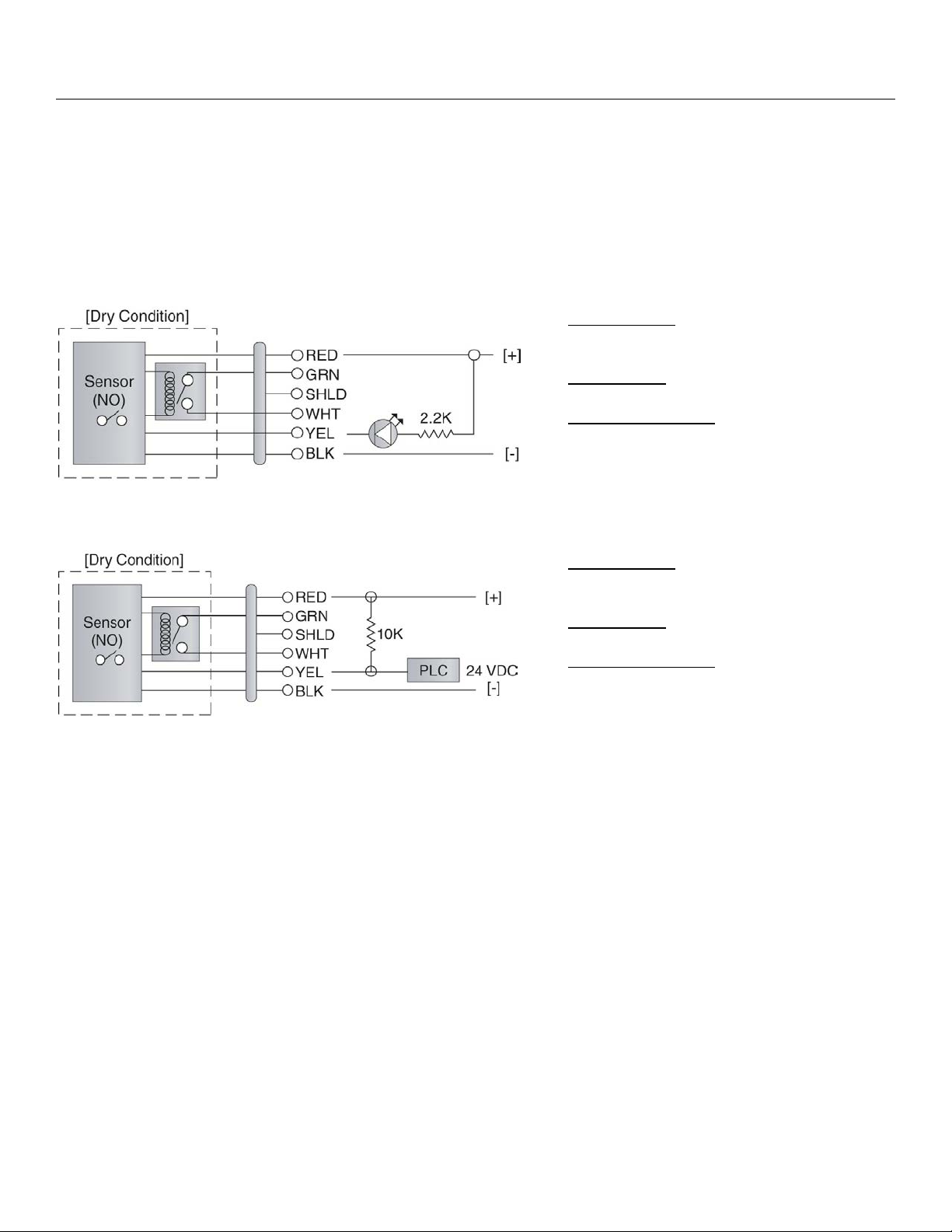
necessary, outputs a preventative maintenance alarm. The Yellow wire is a NPN transistor designed to switch
when a build-up of material prevents the vibration switch from operating at its operational frequency. Use the
Yellow wire to identify when the Vibration switch requires cleaning. To wire the maintenance output wire to an
LED, follow the wiring diagram below. The Yellow wire is connected to the LED and a 2.2kΩ resistor in series
and referenced back to the (+) of the power supply.
Sensor Power
[RED & BLK wires] / 36 VDC Max.
5 ±1mA Dry / 22 ±1mA Wet
Relay Rating
[GRN & WHT wires] / 60 VA
Maintenance Alarm
[YEL wire] / NPN Transistor / 10mA Max.
To wire the maintenance output wire to a PLC, follow the wiring diagram below. The Yellow wire is connected
to the PLC input with a 10 kΩ resistor parallel to the PLC input and the (+) of the power supply.
Sensor Power
[RED & BLK wires] / 36 VDC Max.
5 ±1mA Dry / 22 ±1mA Wet
Relay Rating
[GRN & WHT wires] / 60 VA
Maintenance Alarm
[YEL wire] / NPN Transistor / 10mA Max.
MN301370 Rev B2 5 |
Page 6
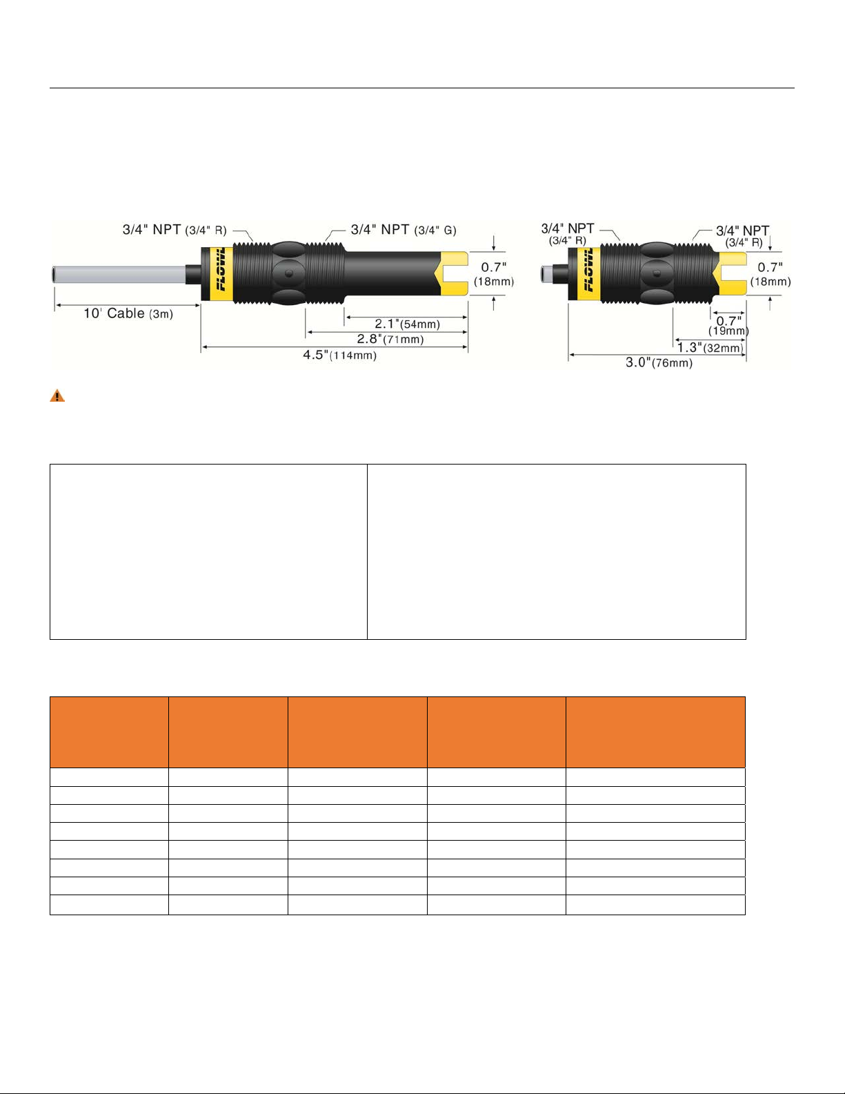
Sensor Information - Ultrasonic Step Three
ULTRASONIC LEVEL SWITCH (LU10 SERIES)
The Ultrasonic switch generates a 1.5 MHz ultrasonic wave from a miniature piezoelectric transducer located
on one side of the gap within it’s sensing tip. Another piezo transducer, located on the other side of the gap,
acts as a microphone, picking up the sound wave. When liquid enters the gap, there is a change in the speed
the wave crosses the gap. This change in the speed of sound identifies whether the sensor is in liquid or in air.
The sensor should be installed so that the liquid will drip out of the gap when the sensor becomes dry.
LU10 SPECIFICATIONS
Sensor material: 1_ _5: PP
2_ _5: PFA
Classification: Intrinsically safe
Approvals: CSA: Class I, Groups A,
B, C & D; Class II, Groups
E, F and G; Class III
EEx: Class 1, Division 1,
Groups A, B, C, D; EEx ib
IIC T6
Cable jacket mat’l: 1_ _5: PP
2_ _5: PFA
Parameters: CSA: Vmax = 32V, Imax = 300
mA, Pmax = 1.3 W; Ci = 0 µF, Li
= 0 µH
EEx: Ui = 32V; Ii = 300 mA; Pi =
1.3 W; Ci = 0 µF; Li = 0 µH
Certificates: CSA: LR 79326
EEx: LCIE 01.E6048 X
CONFIGURATIONS
Thread
Part
Number
LU10-1305 Short (3”) Polypropylene Polypropylene (¾” NPT) x (¾” NPT)
LU10-1325 Short (3”) Polypropylene Polypropylene (¾” R) x (¾”R)
LU10-1405 Long (4.5”) Polypropylene Polypropylene (¾” NPT) x (¾” NPT)
LU10-1425 Long (4.5”) Polypropylene Polypropylene (¾” R) x (¾”G)
LU10-2305 Short (3”) PFA PFA (¾” NPT) x (¾” NPT)
LU10-2325 Short (3”) PFA PFA (¾” R) x (¾”R)
LU10-2405 Long (4.5”) PFA PFA (¾” NPT) x (¾” NPT)
Length
Material
(body)
Material
(cable)
cable
side
X
sensor
side
LU10-2425 Long (4.5”) PFA PFA (¾” R) x (¾”G)
| 6 MN301370 Rev B2
Page 7

Sensor Information - Optic Step Three
OPTIC LEAK DETECTION SWITCH (LO10 SERIES)
The Optic switch use principles of optical refraction to detect the presence or absence of fluid. A pulsed
infrared light beam is internally generated by a light emitting diode and aimed at the slanted optical tip of the
sensor. If the tip is dry, the light beam bounces at a 90 degree angle to a receiving photo transistor, indicating
a dry condition. If the tip is immersed in liquid, the light beam will refract out into the liquid instead of being
reflected to the photo transistor, indicating a wet condition.
The LO10 series is designed as a leak detection switch. The switch should be installed in applications where
under normal conditions, it remains away from the liquid and will only come into contact during a leak.
The Optic Leak Detector cannot detect the presence or absence of specular application liquids that reflect
light (such as milk), or viscous liquids (such as paint) that form a coating on the sensor tip.
LO10 SPECIFICATIONS
Sensor material: 1_ _5: PP
2_ _5: PFA
CONFIGURATIONS
Part
Number
Length
Material
(body)
LO10-1305 Short (3”) Polypropylene Polypropylene (¾” NPT) x (¾” NPT)
LO10-1325 Short (3”) Polypropylene Polypropylene (¾” R) x (¾”R)
LO10-1405 Long (4.5”) Polypropylene Polypropylene (¾” NPT) x (¾” NPT)
LO10-1425 Long (4.5”) Polypropylene Polypropylene (¾” R) x (¾”G)
LO10-2305 Short (3”) PFA PFA (¾” NPT) x (¾” NPT)
LO10-2325 Short (3”) PFA PFA (¾” R) x (¾”R)
LO10-2405 Long (4.5”) PFA PFA (¾” NPT) x (¾” NPT)
LO10-2425 Long (4.5”) PFA PFA (¾” R) x (¾”G)
Cable jacket mat’l: 1_ _5: PP
2_ _5: PFA
Thread
Material
(cable)
cable
side
X
sensor
side
MN301370 Rev B2 7 |
Page 8

Sensor Information - Capacitance Step Three
CAPACITANCE LEVEL SWITCH (LP15 SERIES)
The Capacitance level switch generates a pulse-wave radio frequency signal from the capacitance electrode
located in the sensing tip of each sensor. When liquid comes into contact with the sensing tip, the capacitance
as measured by the sensor changes based on the dielectric constant of the liquid. The guard circuit rejects the
negative effects of coating buildup on the probe by eliminating the coating signal path between the active and
reference electrodes.
The sensor’s operation may vary based on the dielectric properties of various application liquids. The LP15
series sensor is factory-calibrated to be used with liquids with a dielectric value between 20 and 80. Liquids
with a dielectric constant less than 20 will not be detected by an LP15 series sensor.
TABLE OF COMMON DIELECTRIC CONSTANTS
Note: Liquids with a dielectric constant less than 20 will not be detected by an LP15 series level switch.
Acetone ..................... 21
Acetoaldehyde ........ 22.2
Acetyl methyl hexyl
ketone ........................ 28
Alcohol .............. 16 to 31
Ammonia .......... 15 to 25
Acetic acid ...... 4.1 to 6.2
Butyl chloride ............ 9.6
Barium chloride ... 9 to 11
Benzene ................... 2.3
Benzine ..................... 2.3
Barium nitrate ........... 5.6
Bromine .................... 3.1
Chlorobenzene .. 4.7 to 6
Chlorotoluene ........... 4.7
Chloroform ...... 4.5 to 5.0
Chlorine, liquid .......... 2.0
Carbon tetrachloride . 2.2
Cyan ......................... 2.6
Cyclohexane methanol
.................................. 3.7
D.I. Water .................. 20
Ethyl toluene ............. 2.2
Ethyl alcohol .............. 23
Ethylene glycol .......... 37
Ethylene oxide ........... 14
Ethylene dichloride
.......................... 11 to 17
Ethylene chloride ..... 10.5
Ethyl acetate .............6.4
Ethyl salicylate ..........8.6
Ethyl stearate ............2.9
Ethyl silicote ..............4.1
Formic acid ............... 59
Ferric oleate ..............2.6
Freon ........................2.2
Glycerine ................... 47
Glycol ........................ 30
Glycol nitrite .............. 27
Gasoline ............. 2 to 2.2
Hydrochloric acid .......4.6
Isobutyric acid ...........2.7
Isobutyl methyl ketone
................................... 13
Jet fuel ...................... 1.7
Lead carbonate .......... 18
Lead nitrate ................ 38
Methyl salicylate ....... 9.0
Methanol .................... 33
Methyl alcohol ... 33 to 38
Margarine, liquid
........................ 2.8 to 3.2
Methyl acetate .......... 7.3
N-butyl formate ......... 2.4
Nitrobenzene .... 26 to 35
Nitrotoluene ............... 25
Naphthalene ... 2.3 to 2.5
Oils, vegetable 2.5 to 3.5
Oils, mineral ... 2.3 to 2.4
Oils, petroleum
........................ 1.8 to 2.2
Oleic acid ................. 2.5
Propane, liquid
........................ 1.8 to 1.9
Potassium nitrate
........................ 5.0 to 5.9
Potassium chloride ... 5.0
Stearic acid .............. 2.3
Toluene .................... 2.4
Note: Reference a website such as http://www.flowline.com for further dielectric information.
LP15 SPECIFICATIONS
Dielectric range: >20 constants
Conductive range: >100 miromhos
Sensor material: PP
Cable jacket mat’l: PP
CONFIGURATIONS
Thread
Part
Number
Material
(body)
Material
(cable)
cable
side
X
sensor
side
LP15-1405 Polypropylene Polypropylene (¾” NPT) x (¾” NPT)
LP15-1425 Polypropylene Polypropylene (¾” R) x (¾”G)
Trichloroethylene ...... 3.4
Trichloroacetic acid ... 4.5
Terephthalic acid
......................... 1.5 to 1.7
Thinner ...................... 3.7
Urea .......................... 3.5
Vinyl chloride ...... 2.8 to 6
Vinyl alcohol .... 1.8 to 2.0
Water, 20°C ............... 80
Water, 100°C ............. 48
| 8 MN301370 Rev B2
Page 9

Safety Precautions Step Four
About Manual: PLEASE READ THE ENTIRE MANUAL PRIOR TO INSTALLING OR USING THIS
PRODUCT. This manual includes information on all models of Flowline Switch-Tek™ Powered Level
Switches: LZ12, LU10, LP15 and LO10 series. Please refer to the part number located on the sensor label
to verify the exact model which you have purchased.
User’s Responsibility for Safety: Flowline® manufactures a wide range of liquid level switches and
technologies. While each of the these switches are designed to operate in a wide variety of applications, it
is the user’s responsibility to select a switch model that is appropriate for the application, install it properly,
perform tests of the installed system, and maintain all components. The failure to do so could result in
property damage or serious injury.
Proper Installation and Handling: Because this is an electrically operated device, only properly trained
staff should install and/or repair this product. Use a proper sealant with all installations. Note: Always
install the 3/4” Viton gasket with all versions of Switch-Tek™ with metric threads. The G threaded version
will not seal unless the gasket is properly installed. Never over tighten the sensor within the fitting, beyond
a maximum of 80 inch-pounds torque. Always check for leaks prior to system start-up.
Material Compatibility: The LU10 and LO10 series sensors are available in two different wetted materials.
Models L_10-1__5 are made of Polypropylene (PP). Models L_10-2__5 are made of Perfluoroalkoxy
(PFA). The LZ12 series is made of made of Ryton® (40% glass filled) and the LP15 series is made of PP.
Make sure that the model you have selected is compatible with the application liquid. To determine the
chemical compatibility between the sensor and its application liquids, refer to an industry reference such as
the Compass Corrosion Guide (available from Compass Publications).
Wiring and Electrical: The supply voltage used to power the sensor should never exceed a maximum of
36 volts DC (30 VDC for LZ12 series). Electrical wiring of the sensor should be performed in accordance
with all applicable national, state, and local codes.
Flammable, Explosive and Hazardous Applications: Only the LU10-___5 series switch is rated for use
in hazardous locations. Refer to the Certificate of Compliance for all applicable intrinsically safe ratings
and entity parameters. Refer to the National Electric Code (NEC) for all applicable installation
requirements in hazardous locations. DO NOT USE THE LZ12, LP15 OR LO10 SERIES GENERAL
PURPOSE SWITCH IN HAZARDOUS LOCATIONS.
Warning
The rating for the relay is 60 VA (125 VAC max / 1A max). Flowline’s Switch-Tek™ level switches are not
recommended for use with electrically charged application liquids. For most reliable operation, the liquid
being measured may need to be electrically grounded. Always install the 3/4” Viton gasket with all versions of
the powered sensors with metric threads. The G threaded version will not seal unless the gasket is installed
properly.
MAKE A FAIL-SAFE SYSTEM
Design a fail-safe system that accommodates the possibility of switch and/or power failure. FLOWLINE
recommends the use of redundant backup systems and alarms in addition to the primary system. Adding a
redundant high level float switch to the system is a cost effective means to prevent costly tank overflows.
Switch-Tek™ level and leak switches have a single internal relay. The normally open (NO) or normally closed
(NC) operation is user selected based on the desired system control. Always design a fail-safe system that
accommodates for the possibility of functional and/or power failure to the instrument. The "normal" relay state
is where the relay coil is de-energized and the relay indicator is OFF. Therefore, if power is cut OFF to the
switch it will de-energize the relay. Make sure that the de-energized state is the safe state in your system
design. As such, if switch power is lost, a pump will turn OFF if it is connected to the normally open side of the
relay.
MN301370 Rev B2 9 |
Page 10

Installation Step Five
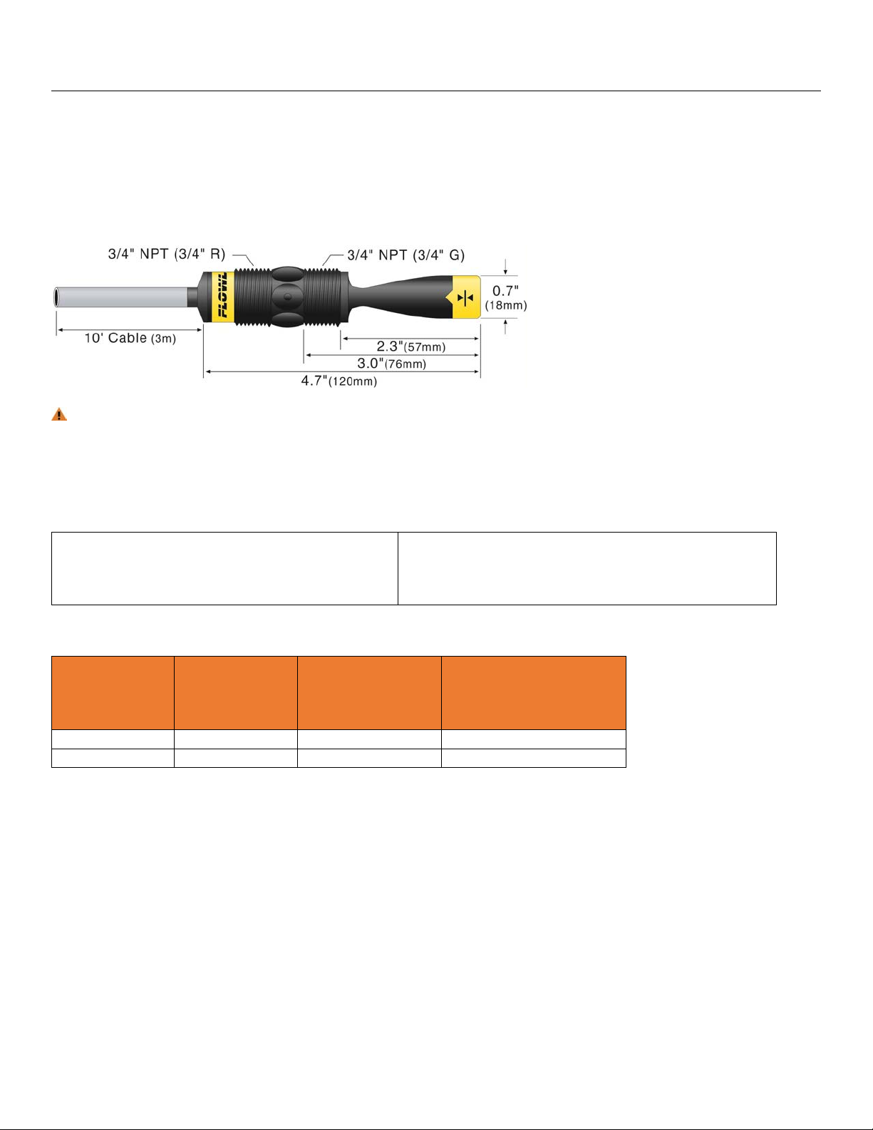
THROUGH WALL INSTALLATION
Switch-Tek™ level switches may be installed through
the top, side or bottom of a tank wall. The sensor has
male 3/4" NPT threads on either side of a 15/16"
wrench flat. This enables the user to select the
sensor’s mounting orientation, installed outside of the
tank in, or inside of the tank out.
Always install the 3/4” Viton gasket with the metric (long sensor length) versions of the L_ _ _-_ _2_. The G
threaded version of the Switch-Tek™ will not seal unless the gasket is installed properly.
TOP WALL INSTALLATION
Switch-Tek
mounting system is an in-tank fitting which enables users to install up to four FLOWLINE sensors of any
technology, to any depth, along the entire length of track. Smart Trak may be installed through the top wall of
any tank using a standard 2" NPT tank adapter. If no tank top installation is available, Flowline's side mount
bracket, LM50-1001, enables Smart Trak to be installed directly to the side wall of a tank. Do not use PFA
Teflon sensors with Smart-Trak.
™ level switches may be installed through the top wall of a tank. Flowline’s Smart Trak LM10 series
Flowline’s Switch Pak LM45 series mounting system is an in-tank fitting which enables users to install one
FLOWLINE sensor, of any technology, to a specific depth. The Flowline sensor may be installed onto the 3/4"
NPT adapter at the end of the Switch Pak. Switch Pak may be installed through the top wall of any tank using a
standard 2" NPT tank adapter. Flowline's side mount bracket, model LM50-1001, may also be used if top wall
installation is not available.
| 10 MN301370 Rev B2
Page 11

Electrical Step Six
SUPPLY VOLTAGE
The supply voltage to the Switch-Tek™ level switch should never exceed a maximum of 36 VDC. Flowline
controllers have a built-in 13.5 VDC power supply which provides power to all of Flowline’s electrically powered
sensors. Alternative controllers and power supplies, with a minimum output of 12 VDC up to a maximum
output of 36 VDC (30 VDC with LZ12 series), may also be used with the Switch-Tek™ level switch.
REQUIRED CABLE LENGTH
Determine the length of cable required between the Switch-Tek™ level switch and its point of termination.
Allow enough slack to ensure the easy installation, removal and/or maintenance of the sensor. The cable
length may be extended up to a maximum of 1000 feet, using a well-insulated, 14 to 20 gauge shielded four
conductor cable.
WIRE STRIPPING
Using a 10 gauge wire stripper, carefully remove the outer layer of insulation from the last 1-1/4" of the
sensor's cable. Unwrap and discard the exposed foil shield from around the signal wires, leaving the drain
wire attached if desired. With a 20 gauge wire stripper, remove the last 1/4" of the colored insulation from the
signal wires.
SIGNAL OUTPUTS (CURRENT SENSING)
The standard method used by Flowline controllers;
this technology uses only two wires (Red and Black).
The sensor draws 5 mA when it is dry and 22 mA
when wet. NC/NO status must be set by the
controller. The White and Green wires are not used.
SIGNAL OUTPUT (RELAY SWITCHING)
Allows the sensor to switch a small load on or off directly, using an internal 1A relay (60 VAC/60 VDC). Only
model LU10-___5 uses the relay and features 4 wires (red, black, white and green) and a shield wire. The
NO/NC status is set by the polarity of the voltage feeding the red and black wires. The green wire is the
common for the relay and the white wire is the NO or NC, depending on the polarity of red and black.
NORMALLY OPEN WIRING
NORMALLY CLOSED WIRING
MN301370 Rev B2 11 |
Page 12

Wiring Step Seven
WIRING TO A FLOWLINE CONTROLLER
LC40 Series Controller (4 or 20 mA output):
LC42-1001 Shown
LC10/LC11 Series Controller (4 or 20 mA output):
LC11-1001 Shown
SWITCHING INDUCTIVE LOADS
The use of suppressors (snubbers) is strongly recommended when switching inductive loads to prevent
disrupting the microprocessor’s operation. The suppressors also prolong the life of the relay contacts.
Suppression can be obtained with a catch diode for DC circuits and a resistor-capacitor (RC) for AC circuits.
Catch Diode
Always use stepper relays between the sensor and external loads.
For DC circuits use a catch diode such as 1N4148, shown on left.
Refer to the following circuits for RC network assembly and installation:
Choose R and C as follows:
R: 0.5 to 1 Ohms for each volt across the contacts
C: 0.5 to 1 μF for each amp through closed contacts
Notes:
1. Use capacitors rated for 250 VAC.
2. RC networks may affect load release time of solenoid loads. Check
to confirm proper operation.
3. Install the RC network at the meters relay screw terminals. An RC
network may also be installed across the load. Experiment for best
results.
| 12 MN301370 Rev B2
Page 13

Wiring Step Seven
WIRING THE RELAY OUTPUT
Switch-Tek™ requires 12 - 36 VDC (30 VDC max. for LZ12 series) power to operate the sensor and switch the
relay. All illustrations below identify a Dry switch state as the normal position of the relay.
Switching a Normally Open DC Load
The Red wire connects to Positive (+) of the power
supply and the Black wire connects to Negative (-).
The LOAD can be attached to either the Green or
White wires. Complete the circuit by connecting the
Green to (+) VDC power or White to (-) VDC power
(see illustration below).
Sensor Power
[RED & BLK wires] / 36 VDC Max.
5 ±1mA Dry / 22 ±1mA Wet
Switching a Normally Open AC Load
The Red wire connects to Positive (+) of the DC
power supply and the Black wire connects to Negative
(-). The LOAD can be attached to the Green wire and
the Hot of the VAC power. Connect the White to the
Neutral of the VAC power (see illustration below).
Switching a Normally Closed DC Load
The Black wire connects to Positive (+) of the power
supply and the Red wire connects to Negative (-).
The LOAD can be attached to either the Green or
White wires. Complete the circuit by connecting the
Green to (+) VDC power or White to (-) VDC power
(see illustration below).
Relay Rating
[GRN & WHT wires] / 60 VA
Switching a Normally Closed AC Load
The Black wire connects to Positive (+) of the DC
power supply and the Red wire connects to Negative
(-). The LOAD can be attached to the Green wire and
the Hot of the VAC power. Connect the White to the
Neutral of the VAC power (see illustration below).
Sensor Power
[RED & BLK wires] / 36 VDC Max.
5 ±1mA Dry / 22 ±1mA Wet
Relay Rating
[GRN & WHT wires] / 60 VA
MN301370 Rev B2 13 |
Page 14

Wiring Step Seven
LU10-_ _ _ 5 ULTRASONIC LEVEL SWITCH ONLY
The LU10-_ _ _ 5 level switch has been approved for use in Class I, Groups A, B, C & D; UNDER
CERTIFICATE NUMBER LR 79326-4. DO NOT USE THE LZ12, LP15 or LO10 SERIES IN INTRINSICALLY
SAFE APPLICATIONS. The Entity parameters for the LU10-_ _ _5 are:
Vmax = 32 VDC / Imax = 0.5 A / Ci = 0 μF / Li = 0 mH
INTRINSICALLY SAFE CONTROL DRAWING
WIRING TO A FLOWLINE CONTROLLER
LC90 Series Controller (4 or 20 mA Signal Output)
LC90 Series
Entity Parameter
Voc = 17.47 VDC
Isc = 0.4597 A
Ca = 0.494 μF
La = 0.119 μH
LU10 series
Entity Parameter
Vmax = 32 VDC
Imax = 0.5 A
Ci = 0 μF
Li = 0 μH
| 14 MN301370 Rev B2
Page 15

Wiring Step Seven
LU10-_ _ _ 5 ULTRASONIC LEVEL SWITCH ONLY (CONTINUED)
The LU10-_ _ _ 5 level switch has been approved for use in Class I, Division 1, Groups A, B, C & D; EEx ib IIC
T6; UNDER CERTIFICATE NUMBER LCIE 01.E6048X. DO NOT USE THE LZ12, LP15 or LO10 SERIES IN
INTRINSICALLY SAFE APPLICATIONS. The Entity parameters for the LU10-_ _ _ 5 are:
North America - Vmax = 32 VDC / Imax = 0.5 A / Pmax = 1.3 W / Ci = 0 μF / Li = 0 μH
Europe - Ui = 32 VDC / Ii = 0.5 A / Pi = 1.3 W / Ci = 0 μF / Li = 0 μH
INTRINSICALLY SAFE CONTROL DRAWING
MN301370 Rev B2 15 |
Page 16

Wiring Step Seven
WIRING AS A P-CHANNEL OR N-CHANNEL OUTPUT
Switch-Tek™ level switch can be substituted for either a P-Channel (PNP, sourcing) output or an N-Channel
(NPN, sinking) output.
Normally Open DC Load as a P-Channel Output
The Red wire connects to Positive (+) of the power
supply and the Black wire connects to Negative (-).
The Green wire is jumped to the Red wire while the
White wire is connected to the LOAD. Jumper the
LOAD to the Negative (-) to complete the circuit.
Sensor Power
[RED & BLK wires] / 36 VDC Max.
5 ±1mA Dry / 22 ±1mA Wet
Normally Open DC Load as a N-Channel Output
The Red wire connects to Positive (+) of the power
supply and the Black wire connects to Negative (-).
The White wire is jumped to the Black wire while the
Green wire is connected to the LOAD. Jumper the
LOAD to the Positive (+) to complete the circuit.
Normally Closed DC Load as a P-Channel Output
The Black wire connects to Positive (+) of the power
supply and the Red wire connects to Negative (-).
The Green wire is jumped to the Black wire while the
White wire is connected to the LOAD. Jumper the
LOAD to the Negative (-) to complete the circuit.
Relay Rating
[GRN & WHT wires] / 60 VA
Normally Closed DC Load as a N-Channel Output
The Black wire connects to Positive (+) of the power
supply and the Red wire connects to Negative (-).
The White wire is jumped to the Red wire while the
White wire is connected to the LOAD. Jumper the
LOAD to the Positive (+) to complete the circuit.
Sensor Power
[RED & BLK wires] / 36 VDC Max.
Relay Rating
[GRN & WHT wires] / 60 VA
5 ±1mA Dry / 22 ±1mA Wet
| 16 MN301370 Rev B2
Page 17

Maintenance Step Eight
GENERAL
Switch-Tek™ level switches may require periodic cleaning to eliminate coating build-up. It is the responsibility
of the user to determine the appropriate maintenance schedule, based on the specific characteristics of the
application liquids.
CLEANING PROCEDURE
1. Power: Make sure that all power to the switch, controller and/or power supply is completely
disconnected.
2. Switch removal: In all through-wall installations, make sure that the tank is drained well below the
sensor prior to removal. Carefully, remove the sensor from the installation.
3. Cleaning the switch: Use a soft bristle brush and mild detergent, carefully wash the Switch-Tek™
level switch. Do not use harsh abrasives such as steel wool or sandpaper, which might damage the
surface sensor. Do not use incompatible solvents which may damage the sensor's PP, PFA, PVDF or
Ryton plastic body.
4. Sensor installation: Follow the appropriate steps of installation as outlined in the Installation section of
this manual.
MAINTENANCE OUTPUT TO LED (LZ12 ONLY)
To wire the maintenance output wire to an LED,
follow the wiring diagram below. The Yellow wire is
connected to the LED and a 2.2kΩ resistor in series
and referenced back to the (+) of the power supply.
MAINTENANCE OUTPUT TO PLC (LZ12 ONLY)
To wire the maintenance output wire to a PLC, follow
the wiring diagram below. The Yellow wire is
connected to the PLC input with a 10 kΩ resistor
parallel to the PLC input and the (+) of the power
supply.
Sensor Power
[RED & BLK wires] / 36 VDC Max.
5 ±1mA Dry / 22 ±1mA Wet
Relay Rating
[GRN & WHT wires] / 60
Maintenance Alarm
[YEL wire] / NPN Transistor / 10mA Max.
VA
MN301370 Rev B2 17 |
Page 18

Maintenance Step Eight
TESTING THE INSTALLATION
1. Power: Turn on power to the controller and/or power supply.
2. Immersing the switch: Immerse the sensing tip in its application liquid, by filling the tank up to the
switches point of actuation. An alternate method of immersing the switch during preliminary testing is
to hold a cup filled with application liquid up to the switch's tip.
3. Test: With the switch being fluctuated between wet and dry states, the switch indicator light in the
controller should turn on and off. If the controller doesn't have an input indicator, use a voltmeter or
ammeter to ensure that the switch produces the correct signal (see below).
4. Point of actuation: Observe the point at which the rising or falling fluid level causes the switch to
change state, and adjust the installation of the switch if necessary.
Example: Testing the LU10 series with a Multimeter set to read current (mA). When wired NO [Red to (+)],
the meter will read 5mA, ±1mA when dry and will read 20mA, ±1mA when wet.
Example: Testing the LU10 series with a multimeter set to read resistance (ohms). When wired NO [Red to
(+)], the meter will read O.L when dry and will read some small amount of resistance (ex. 0.2 Ohms) when wet.
| 18 MN301370 Rev B2
Page 19

Maintenance Step Eight
This Page Intentionally Left Blank
MN301370 Rev B2 19 |
Page 20

Warranty, Returns and Limitations Step Nine
WARRANTY
Flowline warrants to the original purchaser of its products that such products will be free from defects in
material and workmanship under normal use and service in accordance with instructions furnished by Flowline
for a period of two years from the date of manufacture of such products. Flowline's obligation under this
warranty is solely and exclusively limited to the repair or replacement, at Flowline's option, of the products or
components, which Flowline's examination determines to its satisfaction to be defective in material or
workmanship within the warranty period. Flowline must be notified pursuant to the instructions below of any
claim under this warranty within thirty (30) days of any claimed lack of conformity of the product. Any product
repaired under this warranty will be warranted only for the remainder of the original warranty period. Any
product provided as a replacement under this warranty will be warranted for the full two years from the date of
manufacture.
RETURNS
Products cannot be returned to Flowline without Flowline's prior authorization. To return a product that is
thought to be defective, go to flowline.com, and submit a customer return (MRA) request form and follow the
instructions therein. All warranty and non-warranty product returns to Flowline must be shipped prepaid and
insured. Flowline will not be responsible for any products lost or damaged in shipment.
LIMITATIONS
This warranty does not apply to products which: 1) are beyond the warranty period or are products for which
the original purchaser does not follow the warranty procedures outlined above; 2) have been subjected to
electrical, mechanical or chemical damage due to improper, accidental or negligent use; 3) have been modified
or altered; 4) anyone other than service personnel authorized by Flowline have attempted to repair; 5) have
been involved in accidents or natural disasters; or 6) are damaged during return shipment to Flowline. Flowline
reserves the right to unilaterally waive this warranty and dispose of any product returned to Flowline where: 1)
there is evidence of a potentially hazardous material present with the product; or 2) the product has remained
unclaimed at Flowline for more than 30 days after Flowline has dutifully requested disposition. This warranty
contains the sole express warranty made by Flowline in connection with its products. ALL IMPLIED
WARRANTIES, INCLUDING WITHOUT LIMITATION, THE WARRANTIES OF MERCHANTABILITY AND
FITNESS FOR A PARTICULAR PURPOSE, ARE EXPRESSLY DISCLAIMED. The remedies of repair or
replacement as stated above are the exclusive remedies for the breach of this warranty. IN NO EVENT SHALL
FLOWLINE BE LIABLE FOR ANY INCIDENTAL OR CONSEQUENTIAL DAMAGES OF ANY KIND
INCLUDING PERSONAL OR REAL PROPERTY OR FOR INJURY TO ANY PERSON. THIS WARRANTY
CONSTITUTES THE FINAL, COMPLETE AND EXCLUSIVE STATEMENT OF WARRANTY TERMS AND NO
PERSON IS AUTHORIZED TO MAKE ANY OTHER WARRANTIES OR REPRESENTATIONS ON BEHALF
OF FLOWLINE. This warranty will be interpreted pursuant to the laws of the State of California. If any portion
of this warranty is held to be invalid or unenforceable for any reason, such finding will not invalidate any other
provision of this warranty.
For complete product documentation, video training, and technical support, go to flowline.com.
For phone support, call 562-598-3015 from 8am to 5pm PST, Mon - Fri.
(Please make sure you have the Part and Serial number available.)
| 20 MN301370 Rev B2
 Loading...