

Page 1
Model: LI25
Loop-Powered Meter
Quick Start
QS301034 Rev. B
©2010 Flowline, Inc.
All Rights Reserved
Made in USA
Model: LU81, 83, 84-51_1_1-A
EchoSpan®
Welcome to the LI25 Quick Start
The LI25 Quick Start is meant to show some of the more common setup solutions to getting the LI25 up and running
quickly. If you run into an issue that is not addressed here or wish to install or set up with a non-standard
configuration, please address the LI25 Manual or refer to the Flowline website at www.flowline.com.
10500 Humbolt Street, Los Alamitos, CA 90720 USA
Tel: 562.598.3015 Fax: 562.431.8507 www.flowline.com
Spec Tech Industrial Electric
www.spectechind.com
888-773-2832
Spec Tech Industrial Electric
www.spectechind.com
888-773-2832
1 | P a g e
Page 2
Loop-Powered Meter
Mounting Specs
Loop-Powered Meter Panel Mounting Details
We Do Your Level Best
Model
Options Installed
(model numbers for replacement option card)
LI25-1001
General Purpose Loop Powered Display
LI25-2001
Intrinsically Safe Loop Powered Display
Model
Accessories
LM92-1001
Single Display NEMA 4X w/Clear Cover
LIM93-1001
Dual Display NEMA 4X w/Clear Cover
LM91-1001
Single Display NEMA 4X Enclosure
LM91-2001
Dual Display NEMA 4X Enclosure
Spec Tech Industrial Electric
www.spectechind.com
888-773-2832
Spec Tech Industrial Electric
www.spectechind.com
888-773-2832
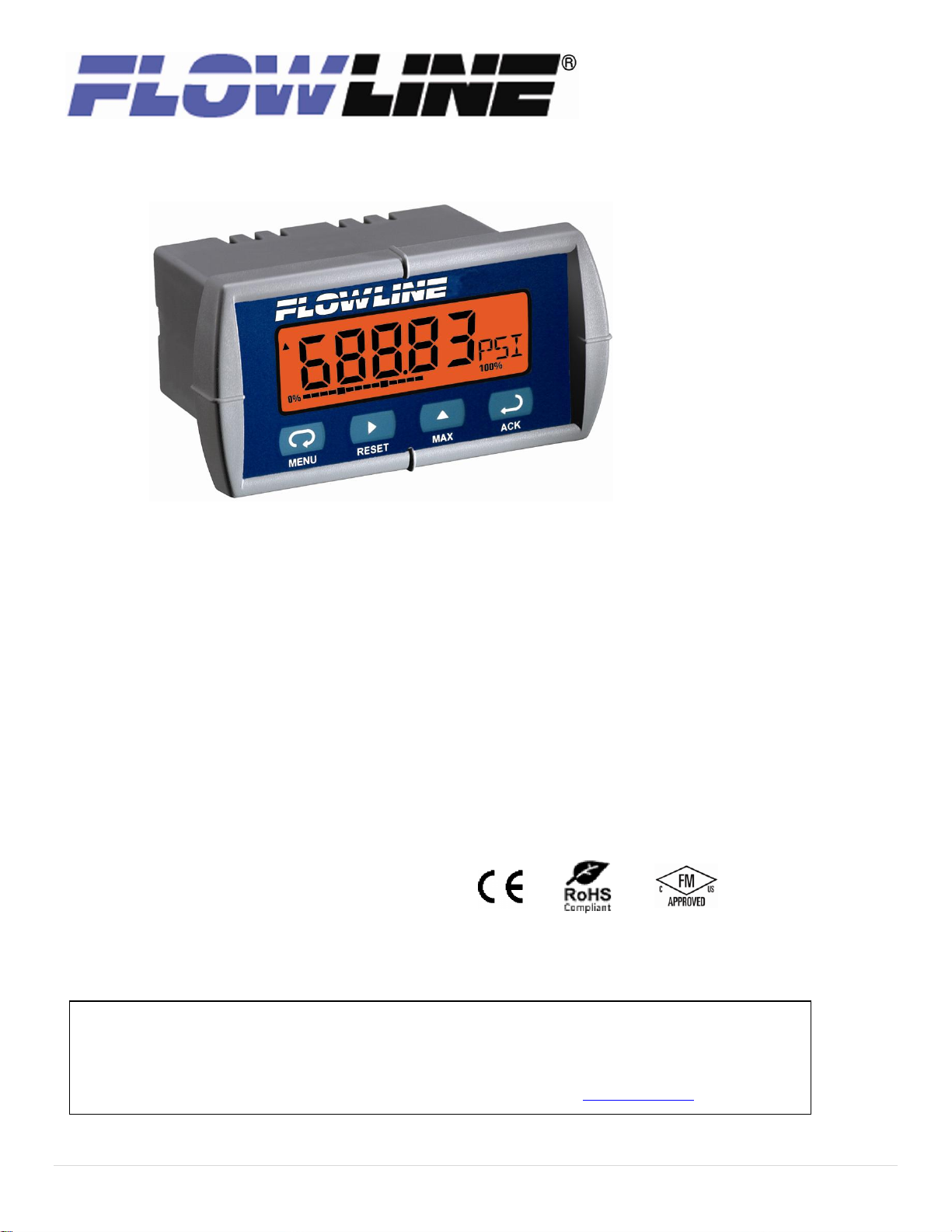
Thank you for purchasing Loop-Powered Meter (LI25). The LI25 Series is a multipurpose, easy to use digital process meter ideal for
level, flow rate, temperature, or pressure transmitter applications. It accepts current and voltage signals (e.g. 4-20 mA, 0-10 V) and has
three front panel buttons that can be programmed for specific operation.
Ordering Information
Installing the Loop-Powered Meter
When unpacking the Loop-Powered Meter, thoroughly inspect the unit for any damage that may have occurred during shipping. Be sure
to report any damage, as well as any missing parts or malfunctions to your supplier or Flowline.
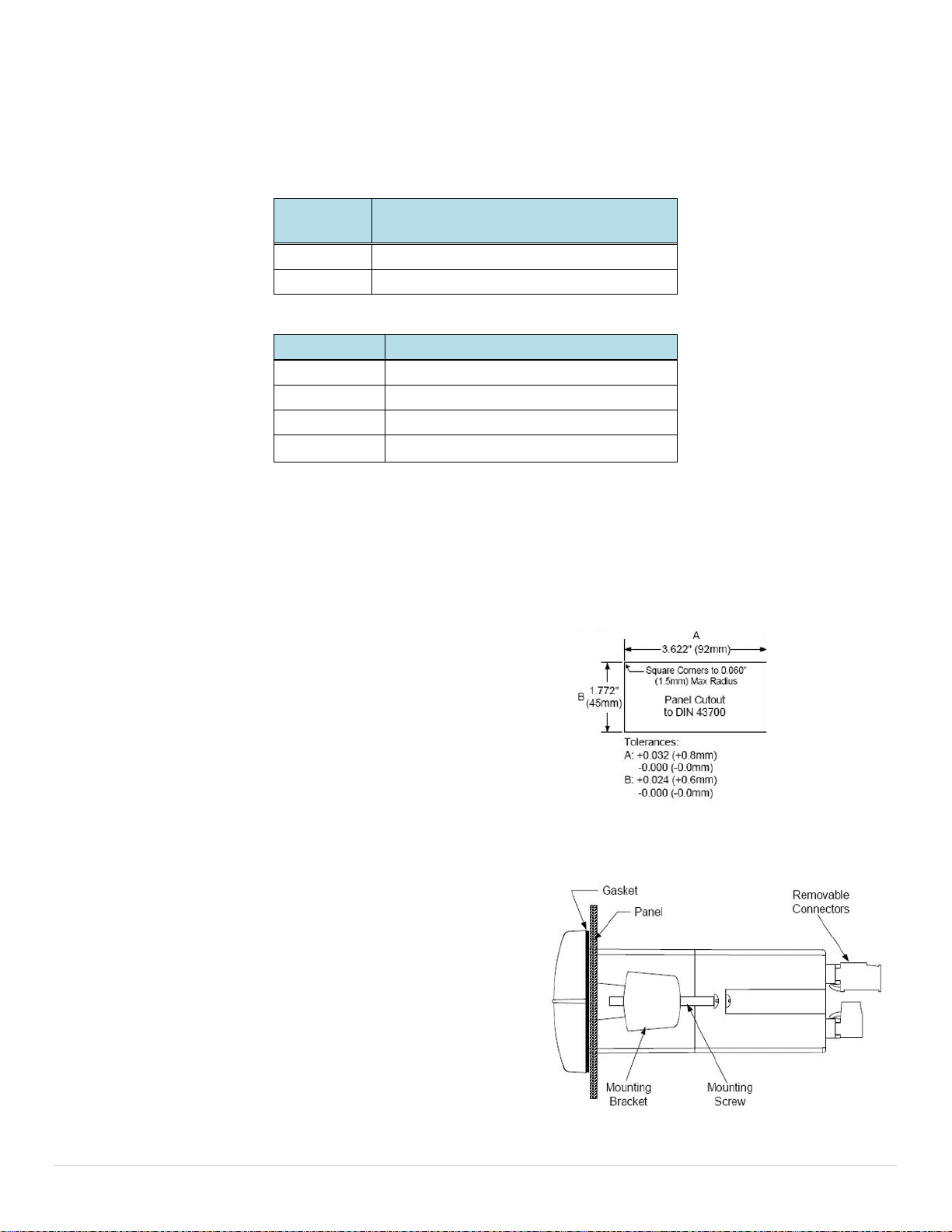
Mounting the Panel
When mounting the panel, first prepare a standard 1/8 DIN panel cutout – 3.622" x 1.772"
(92 mm x 45 mm), as shown in the following diagram.
Allow at least 4.0" (102 mm) clearance behind the panel for wiring.
Be sure to maintain a minimum panel thickness of 0.04" - 0.25" (1.0 mm - 6.4 mm) to
maintain type 4X rating. This would equal 0.06" (1.5 mm) for a steel panel and 0.16"
(4.1 mm) for a plastic panel.
Remove the Loop-Powered Meter’s two mounting brackets. Back-off
the two screws so that there is ¼" (6.4 mm) or less through the bracket.
Slide the bracket toward the front of the case and remove it.
Insert the Loop-Powered Meter into the panel cutout.
Install the mounting brackets and tighten the screws against the panel.
To achieve a proper seal, tighten the mounting bracket screws evenly
until Loop-Powered Meter fits snug against the panel along its short side.
DO NOT OVER TIGHTEN or the rear of the panel may be damaged.
2 | P a g e
Page 3
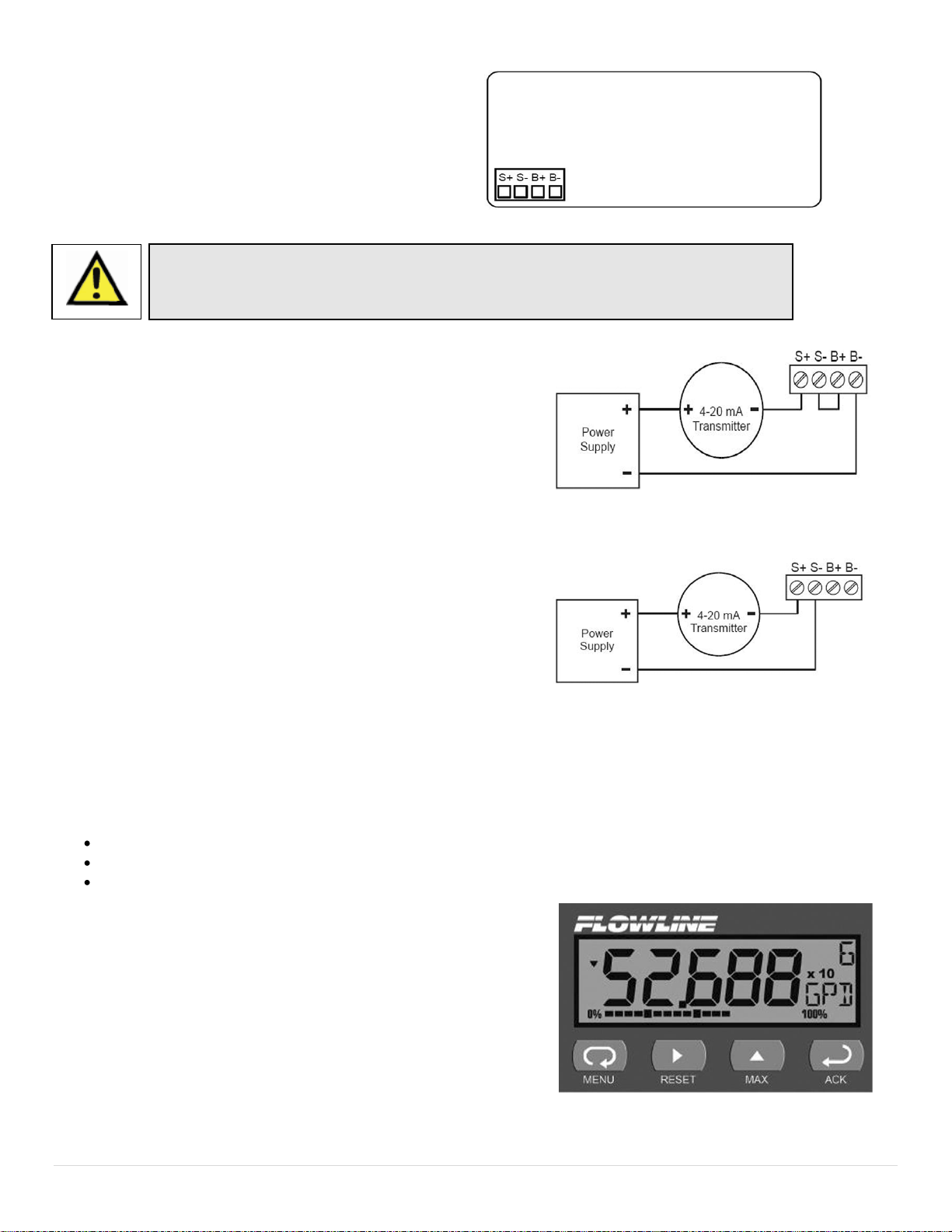
LI25 Rear Panel
LI25 Signal Connections with Backlight
LI25 Signal Connections without Backlight
Connections
Observe all safety regulations. Electrical wiring should be performed in accordance with all
agency requirements and applicable national, state, and local codes to prevent damage to
the meter and ensure personnel safety.
Spec Tech Industrial Electric
www.spectechind.com
888-773-2832
Spec Tech Industrial Electric
www.spectechind.com
888-773-2832
Signal connections are made via a removal, four-terminal
connector.
This section is intended for the LI25-1001 only. LI25-2001
installation must be performed in accordance with Control
Drawing QS301034-1 in order to meet agency approval.
Signal Connections
Signal connections are made via the four-terminal connector on the LI25
back panel. The loop-powered backlight is an optional configuration and
requires a total maximum voltage drop of 5.7 V. The backlight is
recommended for dim lighting conditions and is enabled when wired as
shown in the following diagram.
The backlight may be bypassed if installed in bright lighting conditions to
reduce the maximum voltage drop to 2.0 V as shown in the following
diagram.
The Loop-Powered Meter Interface
The Loop-Powered Meter is factory calibrated to read in milliamps prior to shipment. You will not need to recalibrate the meter. The
calibration equipment is certified to NIST standards.
Overview
There are no jumpers to set for the meter input selection.
All setup and programming is performed through the front panel interface.
After power and input signal connections have been completed and verified, apply power to the meter.
Front Panel Operation
Display
The display shows the units for the level or volume of the tank. It also
includes the unit of measurement being displayed. A graphical
representation of the percent full is displayed along the bottom of the screen.
Buttons
Down the right side of the Loop-Powered Meter’s front panel are four
buttons. It is through these buttons that you will set up and configure the
Loop-Powered Meter. These buttons are explained as follows:
3 | P a g e
Page 4

Menu. Use this button to enter or exit the Loop-Powered Meter’s Programming Mode, view settings, or access advanced features.
Method #1
0% to 100%
Reads to the ones place and is not very accurate
Method #2
0.0% to 100.0%
Reads to the 1/10’s place and provides good
accuracy
Method #3
0.00% to 100.00%
Reads to the 1/100’s place. The accuracy is very
good but may not be practical
Spec Tech Industrial Electric
www.spectechind.com
888-773-2832
Spec Tech Industrial Electric
www.spectechind.com
888-773-2832
Right Arrow/Reset. Use this button to move to the next digit during digit or decimal point programming. This is also used to reset the
max/min readings or other parameter/function assigned through the User menu
Up Arrow/Max. Use this button to scroll through the menus, decimal point, or to change the value of a digit. This is also used to display
max/min readings or other parameter/function assigned through the User menu
ACK. This functions as an ENTER key. Use this button to access a menu or to accept a setting. Programming changes are only saved
after this is pressed.
Programming the Loop-Powered Meter
To enter the Loop-Powered Meter’s Programming menu, press the MENU button. With the UP arrow, you can scroll through three
menu options: Setup, Program, and Password. Each of these options is explained
below.
Setup. This selects: 1. Decimal point position, 2. Units displayed.
Program. This changes Scale options, allows for Calibration and sets the graph.
The display has been calibrated to NIST and will not need to be re-calibrated.
Password. Set or change password access through this option.
QUICK SETUP AND PROGRAMMING
This section will take you through the key steps in setting up and programming the Loop-Powered Meter:
1) Decide on units of measure
2) Select decimal points
3) Set the SCALE function
4) Set the unit in the display
5) Adjust the bar graph
Decide on units of measure
The LI25 series can show level (ex. inches, centimeters, feet, meters, etc) or Volume (gallons, liters, etc.) or any other engineering
units. Please determine the units of operation that you want to appear on the display. This will give you a set point for the environment
you are measuring.
Select decimal points
The decimal point may be set to as many as five decimal places. Use the Decimal Point feature to position the decimal point for all
values displayed. Placement of the Decimal Point can influence the displayed output of your process. For example, setting a scale of 0
to 100% can be show in three different methods:
When selecting a decimal point, take into account the practical scale for reading the level of liquid.
4 | P a g e
Page 5

To set the decimal point:
Input
Display
1
Typically 04.000 mA
Value of tank at Empty
2
Typically 20.000 mA
Value of tank at Full
Spec Tech Industrial Electric
www.spectechind.com
888-773-2832
Spec Tech Industrial Electric
www.spectechind.com
888-773-2832
1) Press the MENU button to bring up the Setup screen.
2) Press the ACK button to bring up the decPT screen.
3) Press the ACK button and the decimal point display screen will appear
as “dd.ddd”. This screen allows you to set the decimal point in your display.
Use the Right Arrow/Reset button to move the decimal point on the screen
from left to right. When it is in the position you desire, press the ACK button
to save that choice.
4) Press the MENU button to close the programming menu.
Setting the SCALE function
The Loop-Powered Meter displays information about tank contents in engineering units. Typically, this means that a full tank is
displayed with a value of 4 mA and an empty tank is displayed with a value of 20 mA. You can scale this information to the levels of full
and empty that you wish. A signal source is not needed to scale the meter.
Enter the value you wish the 4 mA signal to reflect and the value you wish the 20 mA signal to reflect. By configuring the transmitter to 4
mA when the tank is empty and 20 mA when the tank is full, this will show the Empty Display setting (Display 1) as 0 units and the Full
Display setting (Display 2) as the full value of the tank.
The Loop-Powered Meter’s default setting is for 2-point linear configuration.. Each point of the 2-point linear configuration has two
settings, the Input and Display. The Input refers to the current and the Display refers to the display value for the current. For example,
with an Input of 20.0 mA and a display of 100.0, the Loop-Powered Meter will show 100.0
when 20.0 mA is supplied to the device.
In the examples above, the 4 mA/Empty reading could represent 0 Gallons, 0 Feet, 0 Inches or 0.0%. The 20 mA/Full reading could
represent 5,000 Gallons, 10.00 Feet, 120.0 Inches or 100.0%. Setting 4mA for an empty tank and 20 mA for a full tank simplifies
configuration.
5 | P a g e
Page 6

Spec Tech Industrial Electric
www.spectechind.com
888-773-2832
Spec Tech Industrial Electric
www.spectechind.com
888-773-2832
To set the SCALE function:
1) Press the MENU button to bring up the programming menu.
2) Press the Up Arrow/Max to scroll through the Menu options until you reach ProG.
3) Press the ACK button to enter ProG and SCALE will appear.
4) Press the ACK button and Input I (Inpt1) will appear.
5) Press the ACK button to view the current Input 1 Value. This is typically the tank’s empty value for a 4 mA signal. Press the
Right Arrow/Reset button to move the highlighted digit to the right and the Up Arrow/Max button to increase the setting’s
value. When it is in the position you desire, press the ACK button to save that choice and proceed to Display 1.
6) Press the ACK button to view the current DiS 1 Value. Press the Right Arrow/Reset button to move the highlighted digit to
the right and the Up Arrow/Max button to increase the setting’s value. When it is in the position you desire, press the ACK
button to save that choice and proceed to Input 2.
7) Press the ACK button to view the current Input 2 Value. This is typically the tank’s full value for a 20 mA signal. Press the
Right Arrow/Reset button to move the highlighted digit to the right and the Up Arrow/Max button to increase the setting’s
value. When it is in the position you desire, press the ACK button to save that choice and proceed to Display 2.
8) Press the ACK button to view the current DiS 2 Value. Press the Right Arrow/Reset button to move the highlighted digit to
the right and the Up Arrow/Max button to increase the setting’s value. When it is in the position you desire, press the ACK
button to save that choice.
9) Press the MENU button to close the programming menu.
Set the units in the display
The unit in the display is a reminder of what unit you chose when measuring your environment. Some examples of units the LI25 can
measure are:
GAL for gallon measurements
FT for measurements in feet
IN for measurements in inches
PCT for measurements of percent.
6 | P a g e
Page 7

To set the units in the display:
Spec Tech Industrial Electric
www.spectechind.com
888-773-2832
Spec Tech Industrial Electric
www.spectechind.com
888-773-2832
1) Press the MENU button to bring up the Setup screen.
2) Press the ACK button to bring up the dec PT screen.
3) Press the Up Arrow/Max to bring up the units screen. Then, press the ACK button.
4) The following screen allows you to set a three-digit representation of the units in which you’re measuring your environment, as
shown above. Press the Right Arrow/Reset button to move the highlighted digit to the right and the Up Arrow/Max button to
change that digit until it spells the unit, as above.
5) When your unit of measure is displayed, press the ACK button to save that choice.
6) Press the MENU button to close the programming menu.
Adjust the bar graph
The LI25 provides a graphic representation that gives you a current display of your measurement.
To set the bar graph:
1) Press the MENU button to bring up the Setup screen.
2) Press the Up Arrow/Max button to bring up the Program (Prog) screen. Press the ACK button to enter the Prog menu.
3) Press the Up Arrow/Max button to bring up the GrAPH screen. Press the ACK button to enter the GrAPH menu.
4) Press the Up Arrow/Max button to turn the bar graph ON. Then, press the ACK button.
5) The following screen provides the 0% (or 0 PCT) value. Press the ACK button to view the current 0% setting. Use the Right
Arrow/Reset button to move the highlighted digit to the right and the Up Arrow/Max button to change that value. When your
0% value is displayed, press the ACK button to save that choice.
7 | P a g e
Page 8

6) The following screen provides the 100% (or 100 PCT) value. Press the ACK button to view the current 100% setting.. Use the
Warranty
Flowline warrants to the original purchaser of its products that such products will be free from defects in material and
workmanship under normal use and service in accordance with instructions furnished by Flowline for a period, which is
equal to the shorter of one year from the date of purchase of such products or two years from the date of manufacture of
such products. Flowline's obligation under this warranty is solely and exclusively limited to the repair or replacement, at
Flowline's option, of the products or components, which Flowline's examination determines to its satisfaction to be
defective in material or workmanship within the warranty period. Flowline must be notified pursuant to the instructions
below of any claim under this warranty within thirty (30) days of any claimed lack of conformity of the product. Any
product repaired or replaced under this warranty will be warranted only for the remainder of the original warranty period.
Returns
Products cannot be returned to Flowline without Flowline's prior authorization. To return a product that is thought to be
defective, go to www.flowline.com, and submit a customer return (MRA) request form and follow the instructions therein.
All warranty and non-warranty product returns to Flowline must be shipped prepaid and insured. Flowline will not be
responsible for any products lost or damaged in shipment.
Limitations
This warranty does not apply to products which: 1) are beyond the warranty period or are products for which the original
purchaser does not follow the warranty procedures outlined above; 2) have been subjected to electrical, mechanical or
chemical damage due to improper, accidental or negligent use; 3) have been modified or altered; 4) anyone other than
service personnel authorized by Flowline have attempted to repair; 5) have been involved in accidents or natural
disasters; or 6) are damaged during return shipment to Flowline. Flowline reserves the right to unilaterally waive this
warranty and dispose of any product returned to Flowline where: 1) there is evidence of a potentially hazardous material
present with the product; or 2) the product has remained unclaimed at Flowline for more than 30 days after Flowline has
dutifully requested disposition. This warranty contains the sole express warranty made by Flowline in connection with its
products. ALL IMPLIED WARRANTIES, INCLUDING WITHOUT LIMITATION, THE WARRANTIES OF
MERCHANTABILITY AND FITNESS FOR A PARTICULAR PURPOSE, ARE EXPRESSLY DISCLAIMED. The remedies
of repair or replacement as stated above are the exclusive remedies for the breach of this warranty. IN NO EVENT
SHALL FLOWLINE BE LIABLE FOR ANY INCIDENTAL OR CONSEQUENTIAL DAMAGES OF ANY KIND INCLUDING
PERSONAL OR REAL PROPERTY OR FOR INJURY TO ANY PERSON. THIS WARRANTY CONSTITUTES THE
FINAL, COMPLETE AND EXCLUSIVE STATEMENT OF WARRANTY TERMS AND NO PERSON IS AUTHORIZED TO
MAKE ANY OTHER WARRANTIES OR REPRESENTATIONS ON BEHALF OF FLOWLINE. This warranty will be
interpreted pursuant to the laws of the State of California. If any portion of this warranty is held to be invalid or
unenforceable for any reason, such finding will not invalidate any other provision of this warranty.
For complete product documentation, video training, and technical support, go to
www.flowline.com.
For phone support, call 562-598-3015 from 8am to 5pm PST, Mon – Fri
. (Please make sure you have the Part and Serial number available.)
Spec Tech Industrial Electric
www.spectechind.com
888-773-2832
Spec Tech Industrial Electric
www.spectechind.com
888-773-2832
Right Arrow/Reset button to move the highlighted digit to the right and the Up Arrow/Max button to change that value. When
your 100% value is displayed, press the ACK button to save that choice and exit programming.
Safety Concern
Where personal safety or significant property damage can occur due to a spill, the installation must have a redundant backup safety
system installed.
Technical Support
8 | P a g e
 Loading...