

Page 1
FloTech
FT555F
SYSTÈME DE TEST
AUTOMATIQUE ANTI-
DÉBORDEMENT
Systèmes Optique
Systèmes Thermistance
Prise de Terre
Module TIM
10784PA REV C
Dixon
Division Dixon Bayco
Cincinnati, Ohio
Page 2

FloTech FT555F Système de Test Automatique Anti-Débordement
Page 2 10784PA REV C FT555F Testeur
Table des Matières
Introduction ......................................................................................3
Traits principales ..............................................................................3
FT555F Testeur automatique ...........................................................4
FT555F Indicateurs ..........................................................................5
Déballage et configuration initiale ...................................................6
Écran d'accueil .................................................................................7
Pouvoir ON/OFF ..............................................................................8
Instructions installation .............................................................. 9-10
Choisir option de test .....................................................................11
Exécution du test automatique ................................................. 11-12
Test optique .............................................................................. 13-14
Test thermistance ...........................................................................15
Test de boulon de Prise de terre .....................................................16
Test de module ID de remorque .....................................................17
Test humide pour Optique & Thermistance ............................. 18-19
Services technique .........................................................................20
Page 3

FloTech FT555F Système de Test Automatique Anti-Débordement
FT555F Testeur 10784PA REV C Page 3
Introduction
Ce manuel décrit les fonctionnalités, l'utilisation et l'entretien du
système de test automatique anti-débordement FT555F. Le
FT555F est compatible avec toutes les marques de systèmes de
capteurs optiques, systèmes thermo-optique a 2 fils, et systèmes de
surveillance embarqués pour camions indépendamment de
fabrication tant qu'ils sont compatibles avec l'API RP1004 :
pratique recommandée 2003.
Traits principales
Le testeur automatique du système de débordement FLOTECH
FT555F a les caractéristiques suivantes:
- Test automatiquement toutes les 4 fonctions de test,
optique, thermistance, boulon de Prise de terre, et le
numéro TIM.
- Test de toutes les systèmes de capteurs optiques API 5 fils
et rapport le nombre de capteurs fonctionnels / mouillées.
- Test les capteurs thermo-optique a 2 fils et rapport le
nombre de capteurs fonctionnels / mouillées.
- Surveillez jusqu'à huit compartiments.
- Test les boulons de Prise de terre avec la vérification de la
continuité avance et en marche arrière.
- Lire modules TIM et rapport le numéro de série dans
l'affichage.
- Ait le mode "WET TEST" avec alarme pour signaler
lorsque les capteurs sont mouillés.
- Configurez l'écran pour configurer lequel des quatre tests
est activée et permet de configurer le nombre maximum de
compartiments par région.
- Le logiciel peut être mis à jour pour inclure de nouveaux
tests et tests d’avenir étendu et la capacité de résolution des
problèmes.
Page 4
FloTech FT555F Système de Test Automatique Anti-Débordement
Page 4 10784PA REV C FT555F Testeur
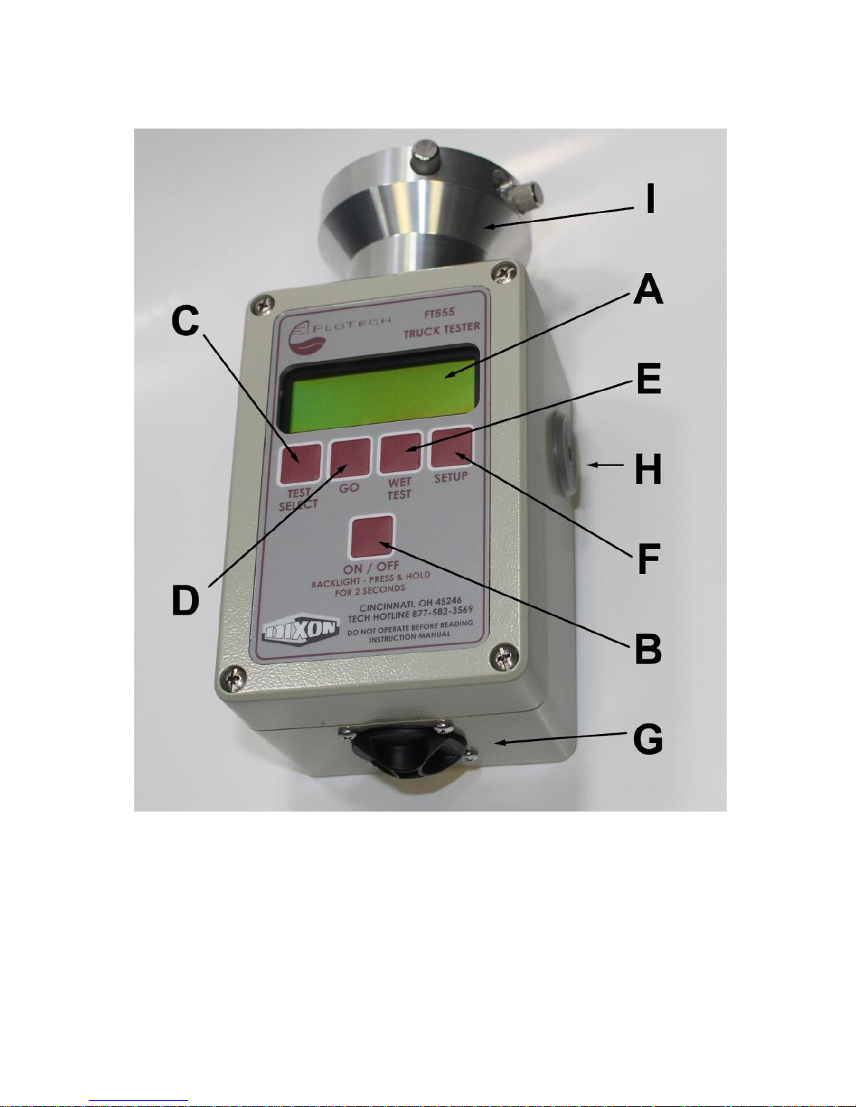
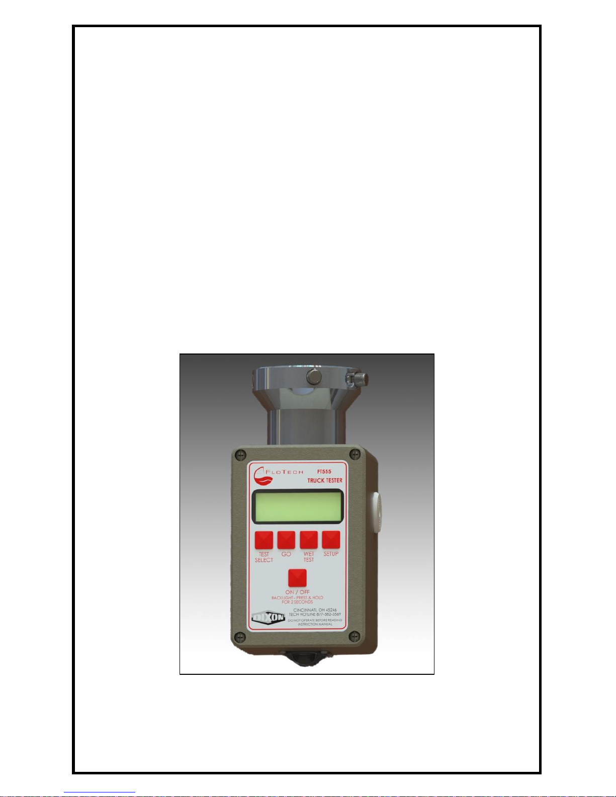
Fig. 1 FT555F Testeur Automatique
Page 5

FloTech FT555F Système de Test Automatique Anti-Débordement
FT555F Testeur 10784PA REV C Page 5
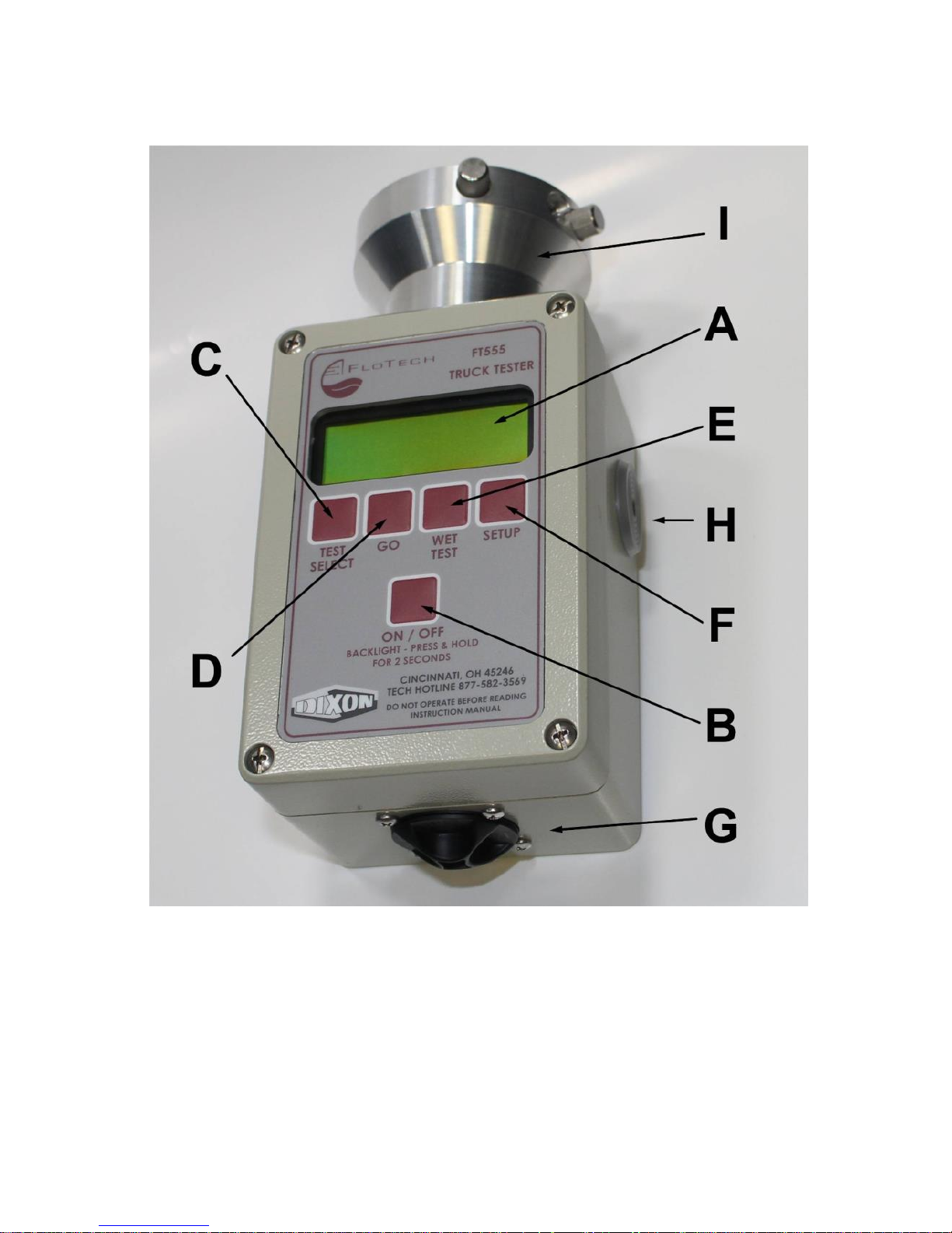
Indicateurs FT555F
A) ÉCRAN LCD
L'écran LCD est l'écran principal où la sélection de test, les résultats des
tests, et des instructions de test seront affichées. Écran est rétroéclairé et
activé à l'aide du bouton ON / OFF.
B) BOUTON ON/OFF
Appuyez sur ce bouton pour activer ou désactiver le Testeur automatique
FT555F. L'unité s'éteint automatiquement après 10 minutes. Appuyez et
maintenir enfoncé ce bouton pendant 2 secondes et le rétroéclairage
s'allumera.
C) SÉLECTION D’UN BOUTON DE TEST
Appuyez sur ce bouton pour faire défiler les tests disponibles.
D) BOUTON DE DÉPART
Appuyez sur ce bouton pour démarrer le test sélectionné.
E) BOUTON POUR TEST MOUILLÉ
Appuyez sur ce bouton en mode de test optique ou thermistance et la
fonction de test mouillé va commencer. Appuyez sur n'importe quel
bouton pour arrêter le test mouillé.
F) BOUTON DE CONFIGURATION INITIALE
Appuyez sur ce bouton pour entrer dans les écrans de configuration.
G) PORTE DE BATTERIE
Twist pour ouvrir, tenir deux cellules D, les points positifs vers la porte
de la batterie (sortie).
H) ALARME
Alarme sonore est émise quand le testeur FT555F automatique est en
mode WET TEST et le capteur est mouillé.
I) CONNECTEUR DE FICHE API
Fiche compatible API avec des broches J-Slot configurables pour les
deux, optiques et les prises de thermistance.
Page 6

FloTech FT555F Système de Test Automatique Anti-Débordement
Page 6 10784PA REV C FT555F Testeur
Déballage et configuration initiale
Étape 1) Lors du déballage du testeur automatique FT555F, vous
trouverez ce qui suit;
a) Testeur automatique FT555F
b) Deux batteries type “D”
c) Trois vis à main J-Slot
d) Ce manuel d'instruction
Étape 2) Vissez les trois vis J-Slot dans les filets marqué "O" pour
la compatibilité de la prise optique et dans les fils J-Slot marquée
"T" pour la compatibilité de prise de thermistance.
Étape 3) Retirez le couvercle de la batterie en tournant antihoraire
jusqu'à ce que la porte s'ouvre. Insérez deux piles de type «D» à la
borne positive de la batterie vers l'extérieur de l'ouverture.
Réinstallez la porte de la batterie en tournant dans le sens horaire.
NE PAS FORCER LA PORTE DE BATTERIE OUVERT OU
FERMÉ
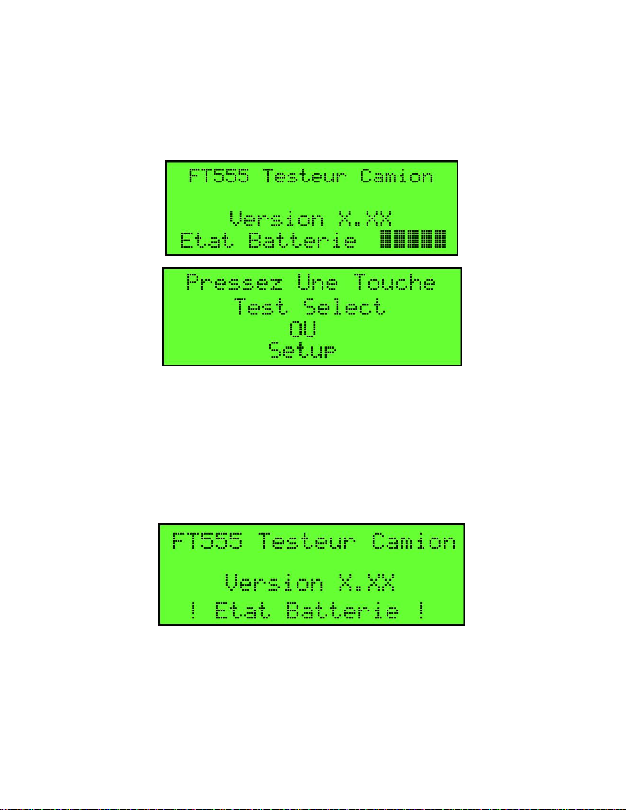
Étape 4) Appuyez sur le bouton ON / OFF une fois. Le FT555F
affichera l'écran de configuration initiale du système indiqué cidessous;
Étape 5) Complétez la configuration initiale du système en suivant
les instructions d'installation à la page 9.
Page 7
FloTech FT555F Système de Test Automatique Anti-Débordement
FT555F Testeur 10784PA REV C Page 7
Écran d'accueil
Après avoir terminé la configuration initiale du système, l'écran de
bienvenue s'affichera. Cet écran s'affichera chaque fois que le
testeur automatique FT555F est allumé.
L'écran d'accueil affiche la version du logiciel le FT555F est en
cours d'exécution et l'état de santé de la batterie dans les bars. 5
barres représentent la capacité de la batterie est pleine. Si deux ou
moins barres sont affichées, un signal sonore d'avertissement sera
émis et un message d'avertissement clignote pendant quelques
secondes. Les batteries doivent être changées lors de votre
prochaine commodité.
Page 8

FloTech FT555F Système de Test Automatique Anti-Débordement
Page 8 10784PA REV C FT555F Testeur
Pouvoir ON/OFF
Appuyez sur le bouton ON / OFF une fois pour allumer le testeur.
Appuyez encore sur le bouton pour arrêter le testeur. Le testeur a
une lumière d`affichage en arrière pour des conditions sombres.
Après avoir allumé le testeur, appuyez et maintenir le bouton ON /
OFF pendant 2 secondes et le rétroéclairage s'allumera. Appuyez
et maintenir pendant 2 secondes et le rétroéclairage s'éteindra.
Page 9
FloTech FT555F Système de Test Automatique Anti-Débordement
FT555F Testeur 10784PA REV C Page 9
Instructions installation
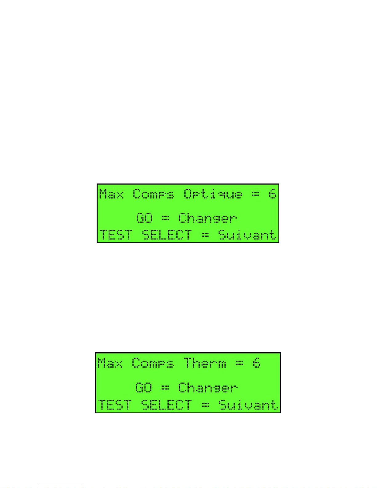
À l'écran "Pressez une Touche", appuyez sur la touche SETUP et
entrer dans le mode de configuration. La première option sera:
MAXIMUM COMPARTIMENTS OPTIQUE = #
Appuyez sur le bouton GO pour basculer entre 6 et 8 pour le
nombre maximal de compartiments. Généralement les États-Unis
à un maximum de 6 compartiments signaux par une prise et le
Canada ou les régions Européennes auront un maximum de 8. Une
fois que le nombre correct de compartiments maximum est affiché,
appuyez sur le bouton TEST SELECT pour accéder à l'écran de
CONFIGURATION suivant.
MAXIMUM COMPARTIMENTS THERMISTANCE = #
Appuyez sur le bouton GO pour basculer entre 6 et 8 nombre
maximal de compartiments. Généralement les États-Unis a un
maximum de 6 compartiments signaux par une prise et le Canada
ou les régions Européennes auront un maximum de 8. Une fois
que le nombre correct de compartiments maximum est affiché,
appuyez sur le bouton TEST SELECT pour accéder à l'écran de
CONFIGURATION suivant.
Page 10

FloTech FT555F Système de Test Automatique Anti-Débordement
Page 10 10784PA REV C FT555F
Testeur
Test Automatique Optique/Therm
Cet écran va activer ou désactiver le testeur optique ou de
thermistance lors de l'exécution d'un test automatique du système
anti-débordement de la remorque. Cette configuration est
seulement pour le mode de test automatique. Tous les quatre tests
sont disponibles pour la sélection manuelle de test.
Certaines régions n`ont pas besoin de testeur optiques ou les
systèmes de type thermistance comme on n'en trouve pas dans
cette région. Exemple, remorques en Californie n'ont pas de prises
de thermistance donc il n'est pas nécessaire d'effectuer le test de la
thermistance. Dans ce cas, le test optique serait activé.
Appuyez sur le bouton «GO» pour choisir entre "Activez les
deux", "Activez OPTIC" ou "Activez THERM" Appuyez sur le
"TEST SELECT" pour passer à l'écran suivant.
Auto Test de boulon de Prise de terre
Appuyez sur le bouton "GO" pour activer ou désactiver le test de
boulon de prise de terre pendant le test automatique. Appuyez
"TEST SELECT" pour passer à l'écran suivant.
Page 11
FloTech FT555F Système de Test Automatique Anti-Débordement
FT555F Testeur 10784PA REV C Page 11
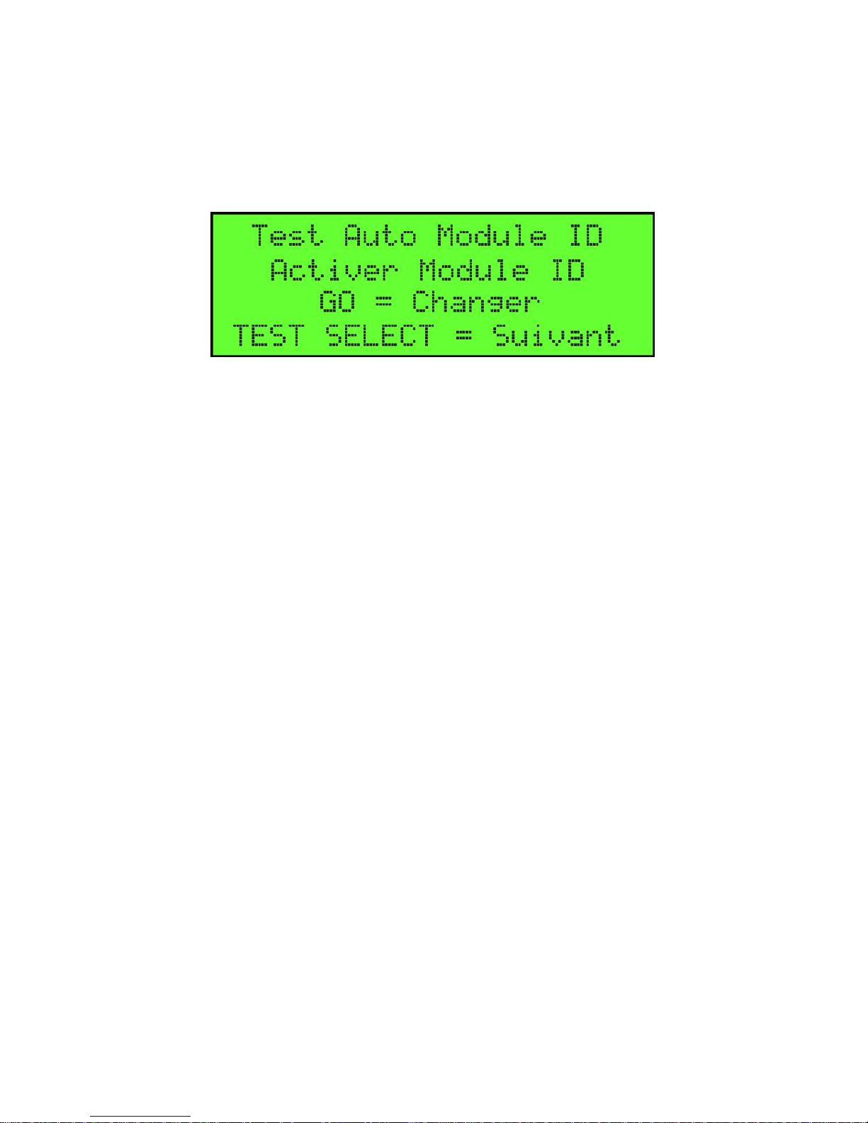
Auto Test Module ID de Camions
Appuyez sur le bouton "GO" pour activer ou désactiver le test de
Module d`identification du camion pendant le test automatique.
Appuyez "TEST SELECT" pour quitter le mode de configuration
et vous retourne à l`écran "PRESS KEY TEST SELECT".
SÉLECTION D`UNE OPTION DE TEST
Lorsque l'écran "Pressez une Touche", à chaque fois que la touche
SELECT TEST est enfoncé, le testeur vas cycler à travers chacun
des cinq modes de test disponibles.
TEST AUTOMATIQUE
TEST OPTIQUE
TEST THERMISTANCE
TEST DE BOULON DE PRISE DE TERRE
TEST DE MODULE ID DE REMORQUE
EFFECTUER LA FONCTION DU TEST
AUTOMATIQUE
Cette option de test va automatiquement tester toutes les options de
test disponibles déjà activées dans la procédure de configuration
ci-dessus, et communiquera les résultats dans un écran RÉUSSI /
ÉCHOUÉ.
Étape 1) Déplacez les vis de serrage J-Slot aux trous appropriés
pour correspondre au type de prise pour être connecté. Suivez le
«O» et le marquage «T» sur le corps de fiche.
Étape 2) Connectez le testeur FT555F automatique à la prise de
remorque.
Étape 3) Appuyez sur le bouton ON/OFF pour allumer le testeur
automatique FT555F. Lorsque l'écran "Pressez une Touche"
Page 12
FloTech FT555F Système de Test Automatique Anti-Débordement
Page 12 10784PA REV C FT555F
Testeur
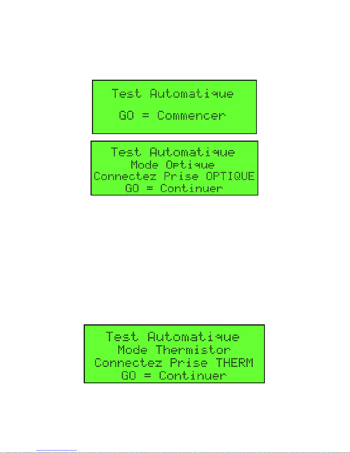
apparaît, appuyez sur "TEST SELECT" une fois pour que l'écran
"Test automatique" apparaît.
Étape 4) Appuyez sur le bouton "GO" pour commencer le test.
Suivez les instructions énumérées sur l'écran d'affichage.
Étape 5) Déplacez les vis J-Slot pour correspondre à la
configuration J-Slot de la prise optique.
Étape 6) Connectez le testeur à la prise optique.
Étape 7) Appuyez sur le bouton GO pour commencer le test
Suivant, le testeur demandera de vous connecter à la prise de
thermistance.
Étape 8) Déplacez les vis J-Slot pour correspondre à la
configuration de la prise de thermistance.
Étape 9) Connectez le testeur à la prise et appuyez sur le bouton
GO pour commencer le test.
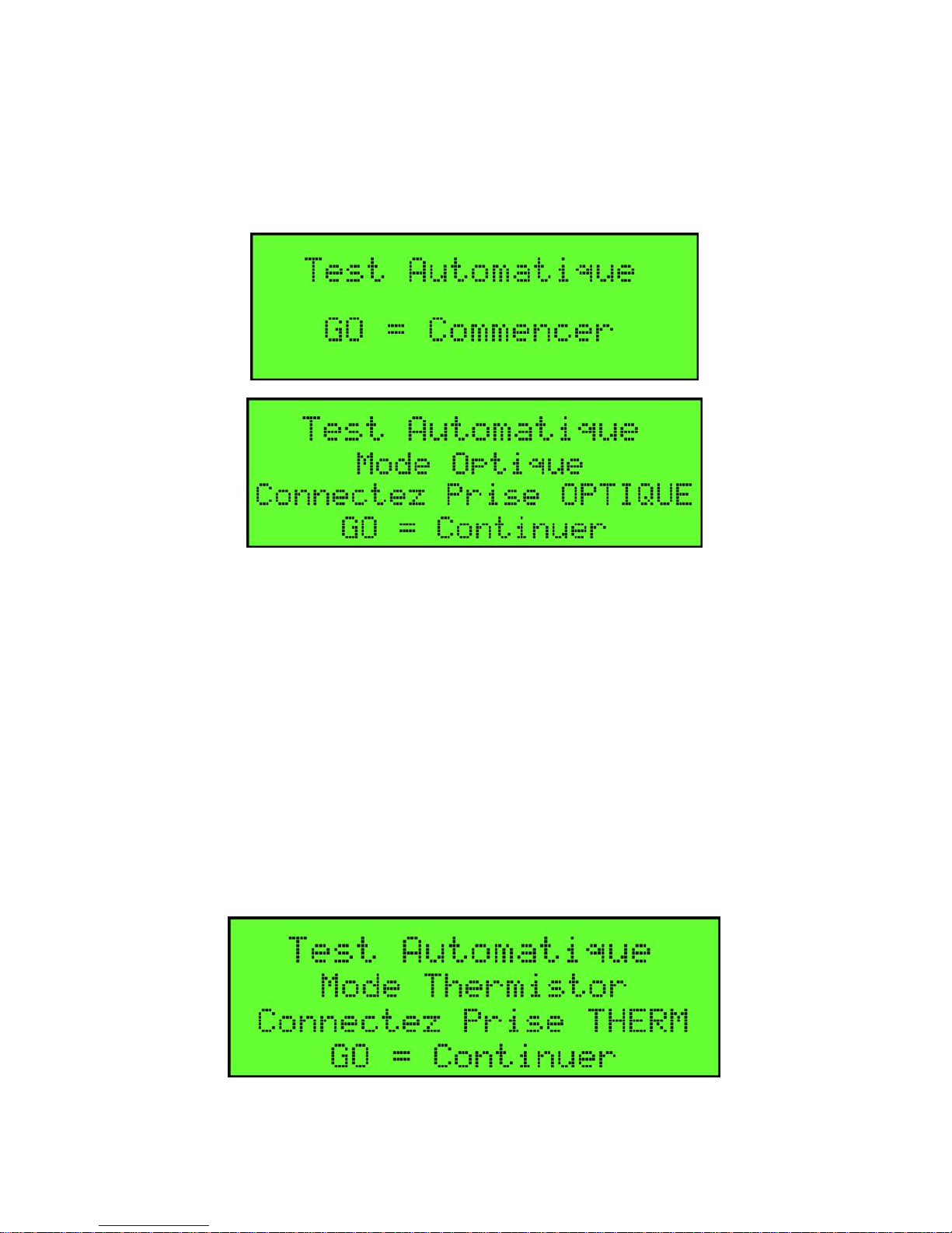
Le testeur testera automatiquement le boulon de prise de terre et le
module TIM si ces options sont activées dans l'écran de
configuration.
Page 13
FloTech FT555F Système de Test Automatique Anti-Débordement
FT555F Testeur 10784PA REV C Page 13
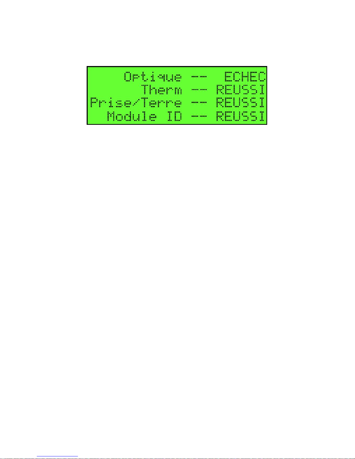
Lorsque le test est terminé, l'écran affichera le statut RÉUSSI /
ÉCHOUÉ de chaque test effectué.
Étape 10) Appuyez sur le bouton "TEST SELECT" pour passer à
un nouveau test, appuyez sur "GO" pour redémarrer le test, ou
appuyez sur le "ON / OFF" pour arrêter le testeur.
TEST OPTIQUE
Ce test permettra de tester le signal optique API des capteurs de
remorque monté ou, moniteur intégré et signaler un Réussi/Échoué
NOTE D`OPERATION:
Ce test fera rapport également le nombre de bons capteurs SI
LES CAPTEURS SONT RELIÉS DIRECTEMENT À LA
PRISE ET PAS DE MONITEUR INTÉGRÉ EST UTILISÉ. Si
votre remorque a un moniteur intégré, le testeur testera le
moniteur intégré comme s'il s'agissait d'un seul capteur. L'état
du capteur relié à un moniteur intégré ne passe pas par le
moniteur à la prise.
Étape 1) Déplacez les vis de serrage J-Slot aux trous appropriés
pour correspondre au type de prise pour être connecté. Suivez le
«O» et le marquage «T» sur le corps de fiche.
Étape 2) Connectez le testeur FT555F automatique pour camion à
la prise de remorque.
Étape 3) Appuyez sur le bouton ON / OFF pour allumer le Testeur
FT555F automatique pour camion. Lorsque l'écran "Pressez une
Touche" apparaît, appuyez sur "TEST SELECT" deux fois pour
que l'écran "Test Optique" apparaît.
Page 14
FloTech FT555F Système de Test Automatique Anti-Débordement
Page 14 10784PA REV C FT555F
Testeur
Étape 4) Appuyez sur le bouton "GO" pour commencer le test.
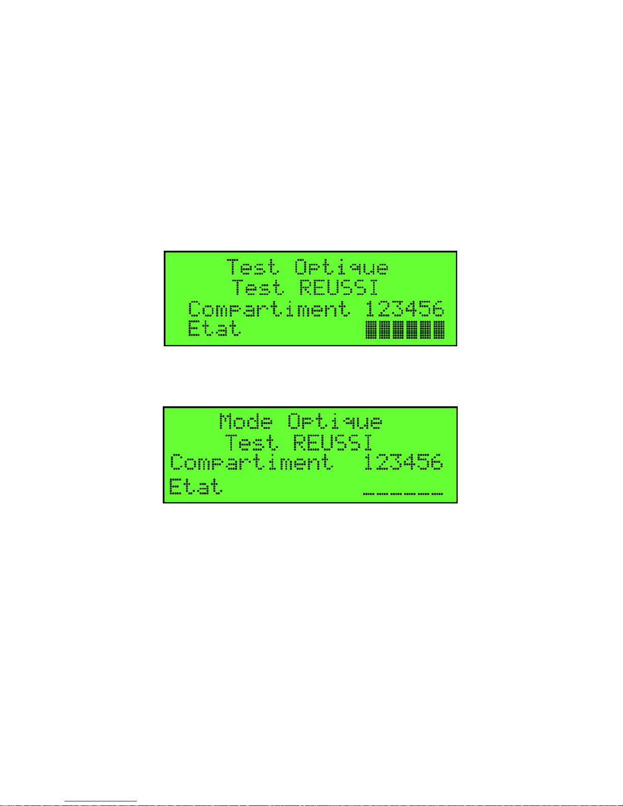
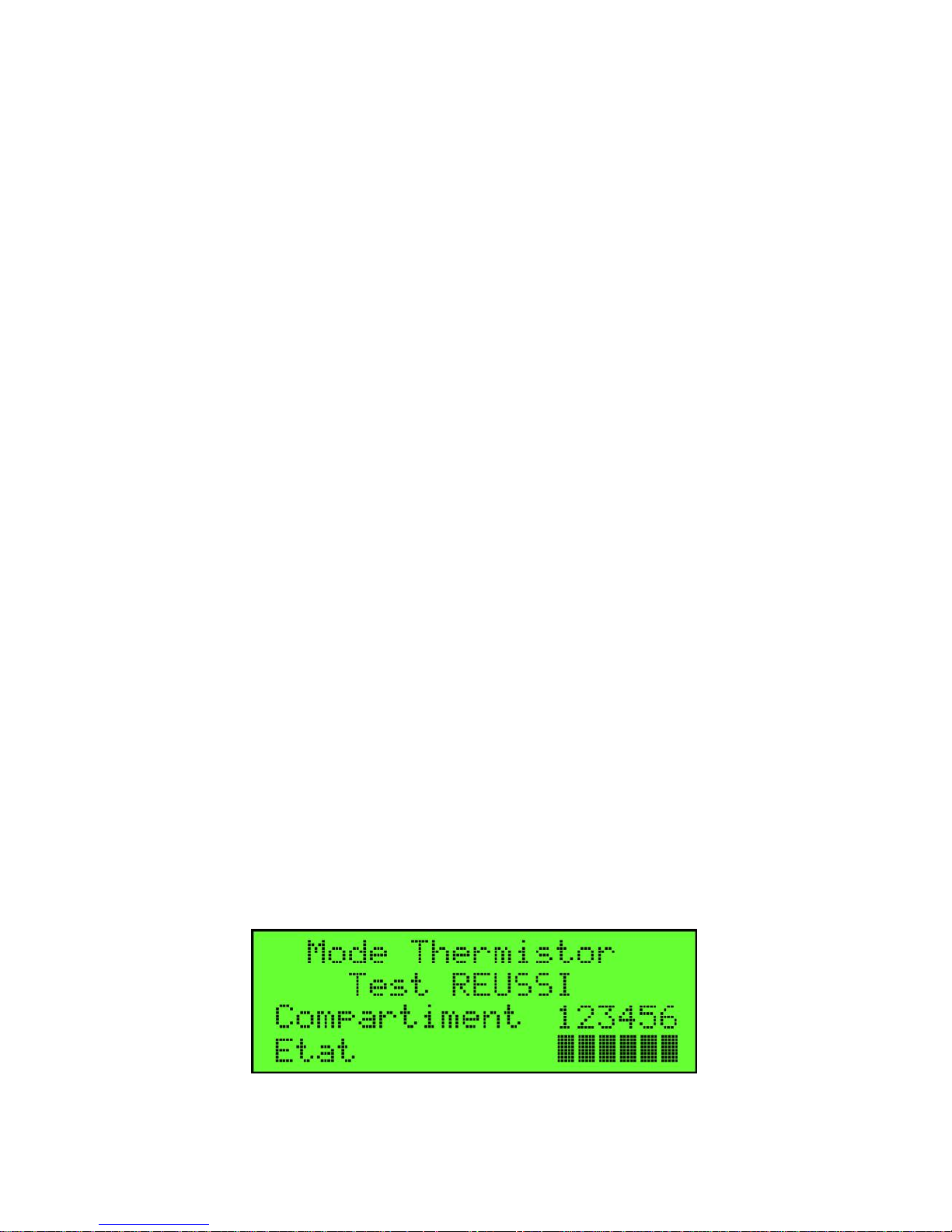
Lorsque le test est terminé, l'écran affichera l'état RÉUSSI /
ÉCHOUÉ et un état mouillé / sec pour chacun des compartiments
activée lors de l'installation. Un carré sous le numéro indique un
capteur sec ou un tableau de bord sous le numéro indique un
capteur mouillé ou manquant. Si vous êtes connecté à un moniteur
intégré, des lignes pointillées vont montrer et pas de barres noires.
Étape 5) Appuyez sur le "TEST SELECT" pour passer à un
nouveau test, appuyez sur "GO" pour redémarrer le test, ou
appuyez sur le "ON / OFF" pour arrêter le testeur.
Réussi quand optique est relié à des capteurs indiqué ci-dessus. Un
carré noir s'allume pour chaque bon capteur.
Le test optique Réussi lorsqu'il est connecté à un moniteur intégré,
va montrer des tirets pour l'état du capteur. Moniteurs intégré n'ont
pas une connexion de diagnostic pour le moniteur de rampe de
chargement, et ne passent pas le nombre de bons capteurs sur le
moniteur intégré à la prise.
Page 15
FloTech FT555F Système de Test Automatique Anti-Débordement
FT555F Testeur 10784PA REV C Page 15
TEST THERMISTANCE
Ce test permettra de tester le signal thermistance API des capteurs
de remorque monté à bord ou moniteur intégré et signaler un
RÉUSSI / ÉCHOUÉ.
NOTE D` OPERATION:
Ce testeur n'est pas compatible avec l'ancien style analogue
"capteurs vert ou à pointe argenté". Ces appareils nécessitent le
testeur FT510.
Étape 1) Déplacez les vis de serrage J-Slot aux trous appropriés
pour correspondre au type de prise pour être connecté. Suivez le
«O» et le marquage «T» sur le corps de fiche.
Étape 2) Connectez le testeur automatique FT555F pour camion à
la prise de remorque.
Étape 3) Appuyez sur le bouton ON / OFF pour allumer le testeur
automatique FT555F. Lorsque l'écran "Pressez une Touche"
apparaît, appuyez sur "TEST SELECT" trois fois pour que l'écran
"Test Thermistor" apparaît.
Étape 4) Appuyez sur le bouton "GO" pour commencer le test.
Lorsque le test est terminé, l'écran affichera l'état RÉUSSI /
ÉCHOUÉ et l'état mouillé / sec pour chacun des compartiments
activée lors de l'installation. Un carré sous le numéro indique un
capteur sec, ou un tableau de bord sous le numéro indique un
capteur mouillé ou manquant. Si vous êtes connecté à un moniteur
intégré, des lignes pointillées vont montrer et pas de barres noires.
Étape 5) Appuyez sur le bouton "TEST SELECT" pour passer à
un nouveau test, appuyez sur "GO" pour redémarrer le test, ou
appuyez sur le "ON / OFF" pour arrêter le testeur.
Page 16
FloTech FT555F Système de Test Automatique Anti-Débordement
Page 16 10784PA REV C FT555F
Testeur
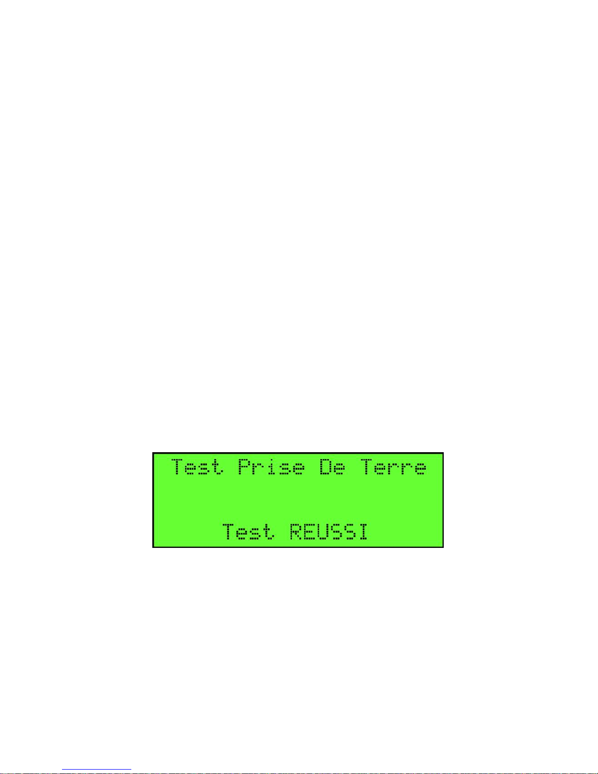
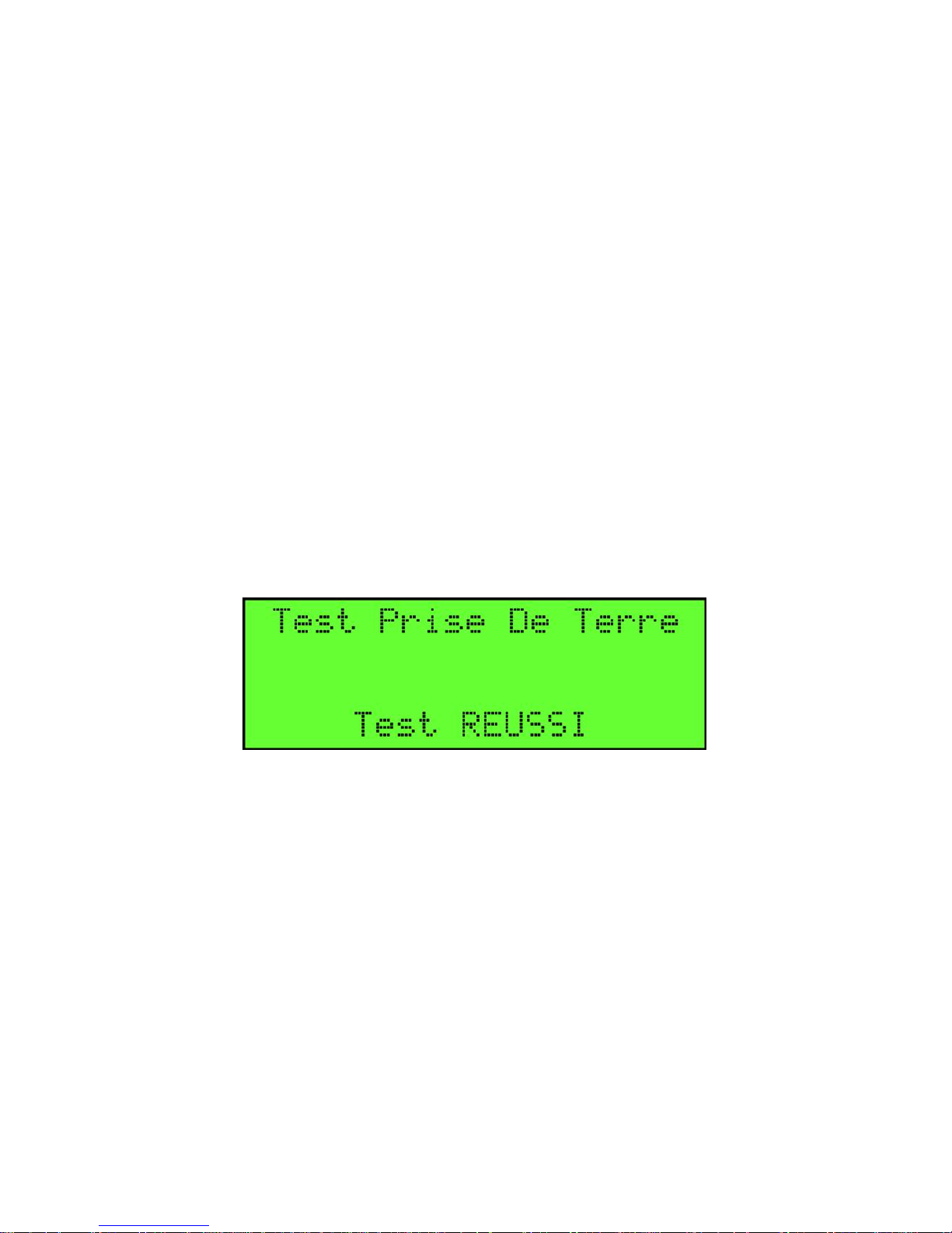
TEST DE BOULON DE PRISE DE TERRE
Ce test permettra de tester le boulon de prise de terre en utilisant le
test de la marche avant et arrière pour vérifier le bon
fonctionnement de la diode à l'intérieur du boulon de prise de terre.
Le testeur signalera un RÉUSSI / ÉCHOUÉ.
Étape 1) Déplacez les vis de serrage J-Slot aux trous appropriés
pour correspondre au type de prise pour être connecté. Suivez le
«O» et le marquage «T» sur le corps de fiche.
Étape 2) Connectez le testeur automatique FT555F pour camion à
la prise de remorque.
Étape 3) Appuyez sur le bouton ON / OFF pour allumer le testeur
automatique FT555F. Lorsque l'écran "Pressez une Touche"
apparaît, appuyez sur "TEST SELECT" quatre fois pour que
l'écran "Test Prise de Terre" apparaît.
Étape 4) Appuyez sur le bouton "GO" pour commencer le test.
Lorsque le test est terminé, l'écran affichera l'état RÉUSSI /
ÉCHOUÉ.
Étape 5) Appuyez sur "TEST SELECT" pour passer à un nouveau
test, appuyez sur "GO" pour redémarrer le test, ou appuyez sur le
"bouton ON / OFF" pour arrêter le testeur.
Page 17
FloTech FT555F Système de Test Automatique Anti-Débordement
FT555F Testeur 10784PA REV C Page 17
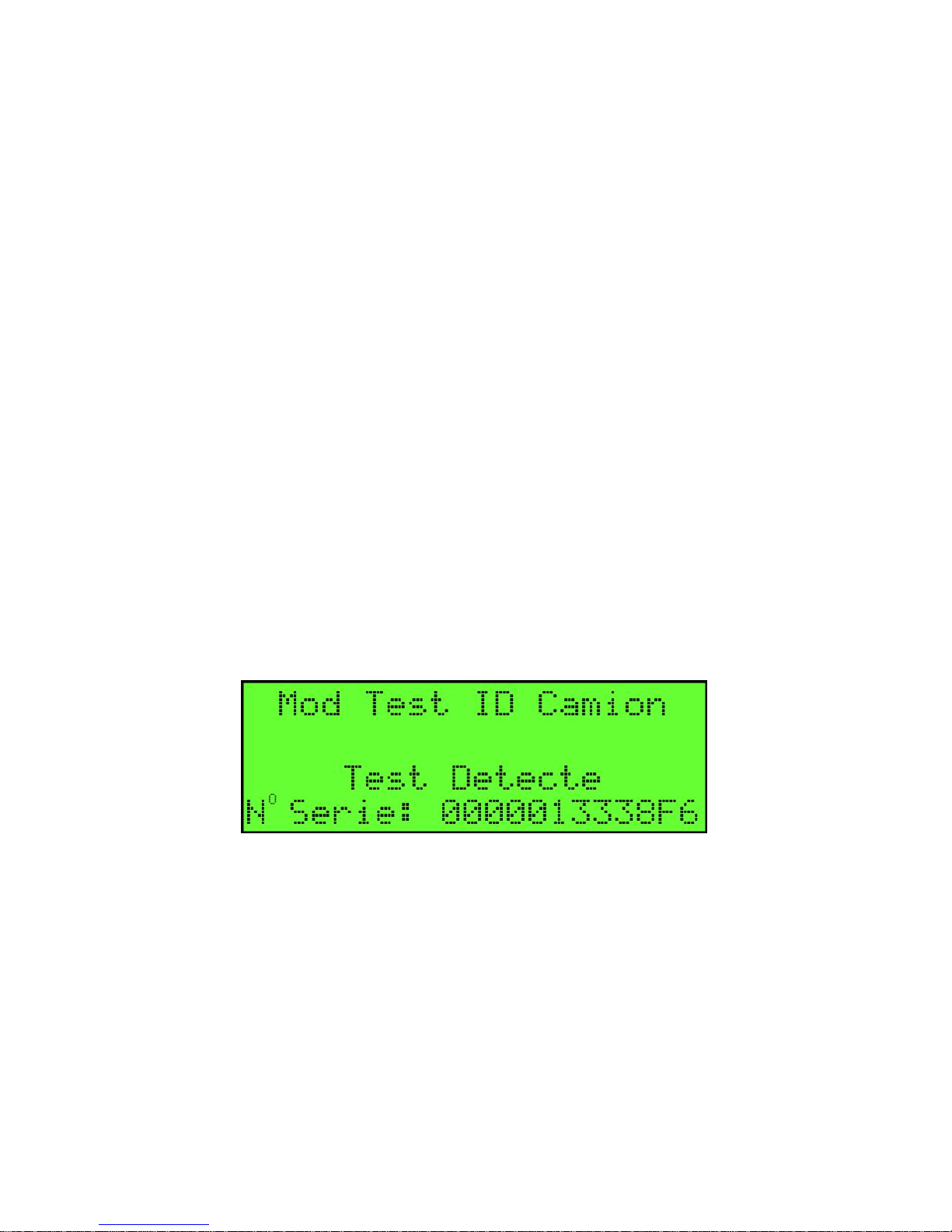
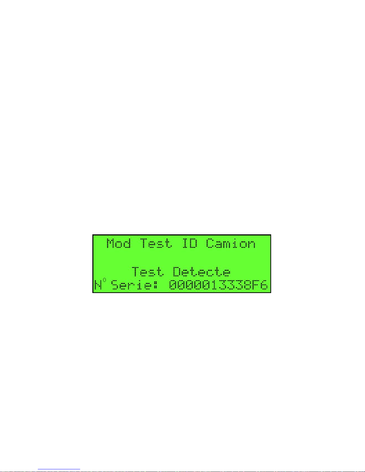
TEST DE MODULE ID DE REMORQUE
Ce test permettra de tester le module remorque d'identité et rapport
le numéro de série à 12 chiffres stocké à l'intérieur du module
d'identification. S'il n'y a pas de module de remorque d'identité ou
le test échoue, l'écran affiche "TIM non Détecté"
Étape 1) Déplacez les vis de serrage J-Slot aux trous appropriés
pour correspondre au type de prise pour être connecté. Suivez le
«O» et le marquage «T» sur le corps de fiche.
Étape 2) Connectez le testeur automatique FT555F à la prise de
remorque.
Étape 3) Appuyez sur le bouton ON / OFF pour allumer le testeur
automatique FT555F. Lorsque l'écran "Pressez une Touche"
apparaît, appuyez sur "TEST SELECT" cinq fois pour que l'écran
"Mode Module ID Camion" apparaît.
Étape 4) Appuyez sur le bouton "GO" pour commencer le test.
Lorsque le test est terminé, l'écran fera rapport au numéro de série
à 12 chiffres ou montrer "TIM non Détecté ".
Étape 5) Appuyez sur "TEST SELECT" pour passer à un nouveau
test, appuyez sur "GO" pour redémarrer le test, ou appuyer sur le
bouton "ON / OFF" pour arrêter le testeur.
Page 18
FloTech FT555F Système de Test Automatique Anti-Débordement
Page 18 10784PA REV C FT555F
Testeur
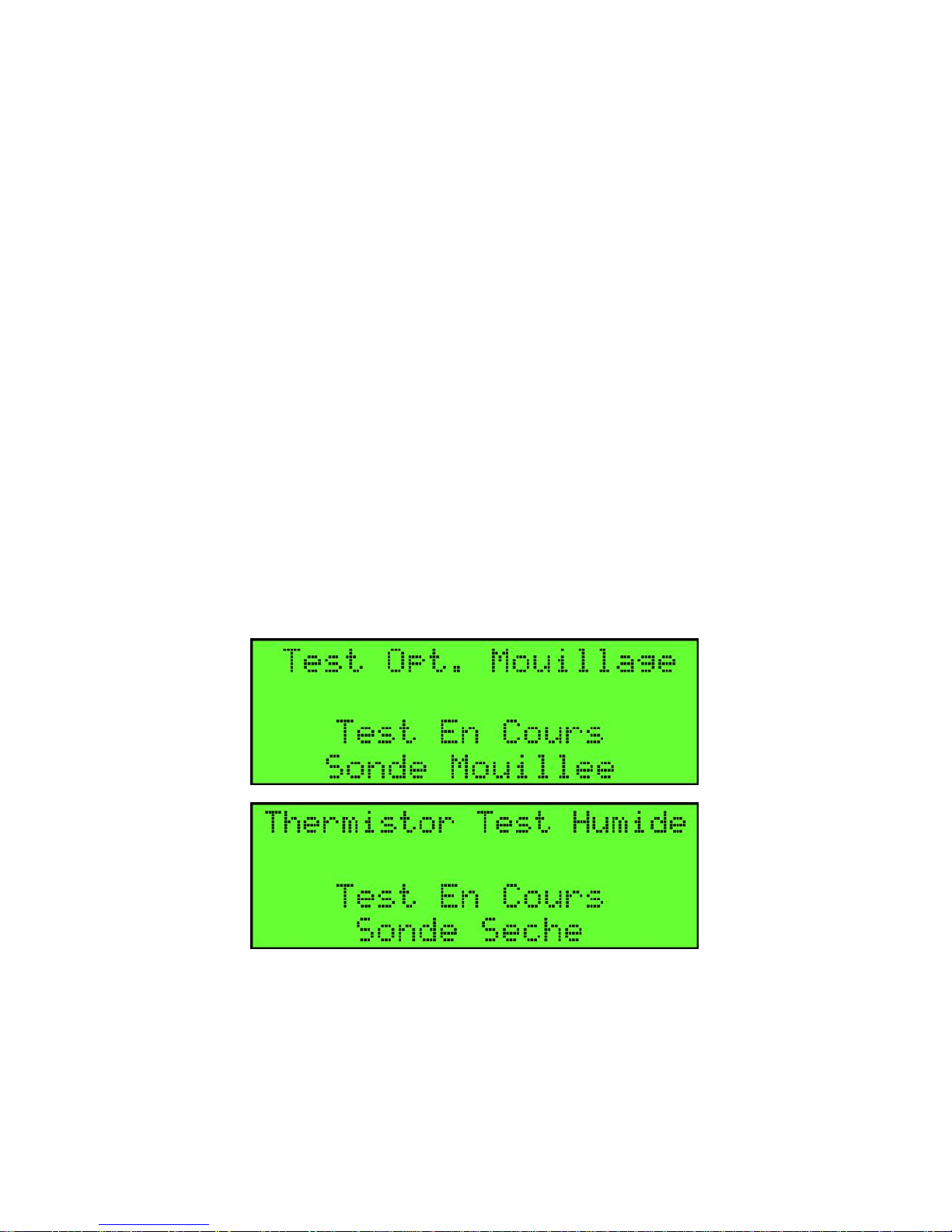
TEST HUMIDE POUR OPTIQUE &
THERMISTANCE
NOTE: LA FONCTION DU TEST MOUILLÉ EST
DESTINÉE A ÊTRE UTILISÉ SUR LES SYSTÈMES EN
MARCHE. SI LE SYSTÈME A UN PROBLÈME, IL DOIT
ÊTRE RÉPARÉ AVANT DE FAIRE UN TEST MOUILLÉ.
Étape 1) Déplacez les vis de serrage J-Slot aux trous appropriés
pour correspondre au type de prise pour être connecté. Suivez le
«O» et le marquage «T» sur le corps de fiche.
Étape 2) Connectez le testeur automatique FT555F pour camion à
la prise de remorque.
Étape 3) Appuyez sur le bouton ON / OFF pour allumer le testeur
automatique FT555F. Lorsque l'écran "Pressez une Touche"
apparaît, appuyez sur "TEST SELECT" plusieurs fois jusqu'à ce
que le "Test Optique" ou "Test Thermistor " apparaisse, dépendant
de la prise que le testeur est connecté à.
Étape 4) Appuyez sur le bouton "WET TEST" pour commencer le
test mouillé.
Page 19
FloTech FT555F Système de Test Automatique Anti-Débordement
FT555F Testeur 10784PA REV C Page 19
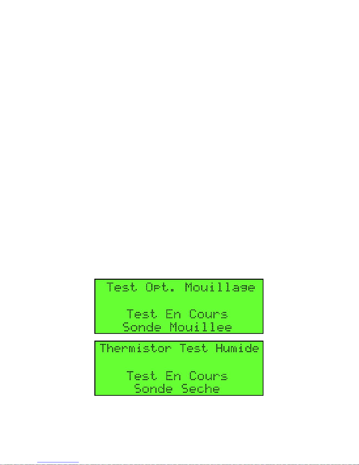
Étape 5) Le FT555F testera plusieurs fois pour la présence de
capteurs mouillé connectés à la prise.
Étape 6) Essai de Trempette dans un compartiment et écouter pour
un bip. L'affichage indiquera également la présence d'un capteur
mouillé.
Étape 7) Continuez à tester chaque compartiment.
Étape 8) Arrêtez le test mouillé en appuyant sur n'importe quelle
touche.
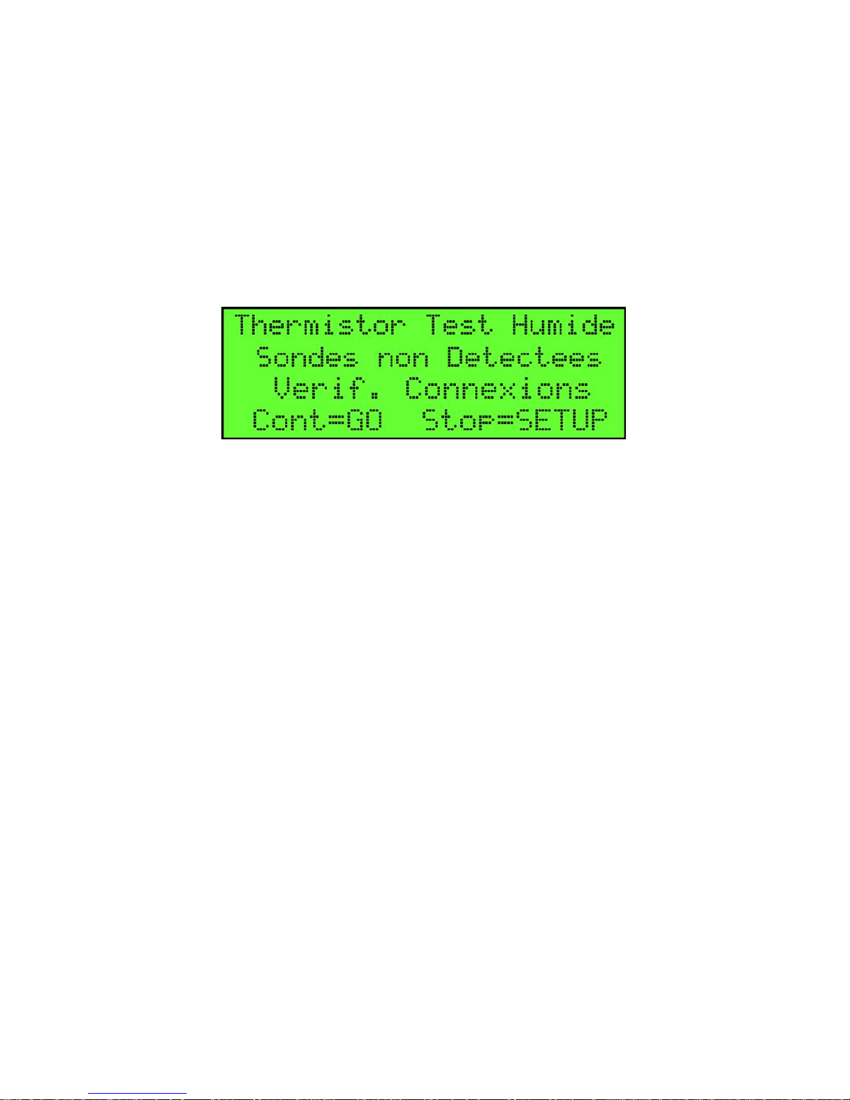
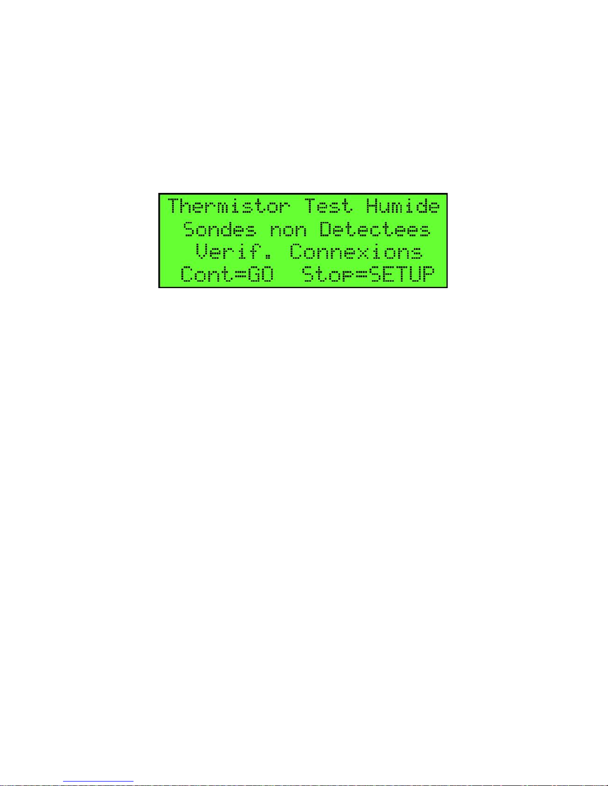
NOTE: SI LE TESTEUR NE VOIT PAS DES CAPTEURS
OU N'EST PAS CONNECTÉ, IL AFFICHE L'ÉCRAN AU-
DESSUS JUSQU'À CE QU'IL VOIE UN CAPTEUR OU LE
TEST ARRÊTE.
Page 20

FloTech FT555F Système de Test Automatique Anti-Débordement
Page 20 10784PA REV C FT555F
Testeur
ATTENTION:
Le FT555F n'est pas certifié conçus pour une utilisation dans
un endroit dangereux Classe I, Division 1. Vous devez éviter
l'utilisation dans des atmosphères explosives ou inflammables.
Résolution des problèmes:
A. Si le FT555F ne démarre-pas ou arrête pendant
l'utilisation, vérifiez l'indicateur de batterie sur l'écran
d'accueil et ou remplacer les piles.
B. Si le FT555F semble se figer, retirez les piles pour forcer
l'appareil à s'éteindre. Réinstallez les batteries et
commencez la procédure de test. En enlevant les batteries
vous forcerez le FT555F de se redémarrer à l'écran
d'accueil.
Ligne d'assistance technique
(877) 582-3569
Contactez le support technique téléphonique FLOTECH pour de
l'aide:
Résolution des problèmes pour les systèmes de
débordement.
Vérification des composants défectueux
Pour demander un RGA pour les produits défectueux sous
la garantie de FLOTECH.
Page 21
FloTech
FT555F
Automatic Overfill System
Tester (with French Display)
Optic Systems
Thermistor Systems
Ground Bolt
TIM Module
10784PA REV C
Dixon
Dixon Bayco Division
Cincinnati, Ohio
Page 22

FloTech FT555F Automatic Overfill System Tester
Page 2 10784PA REV C FT555F Truck Tester
Table of Contents
Introduction ......................................................................................3
Main Features...................................................................................3
FT555F Automatic Tester ................................................................4
FT555F Indicators ............................................................................5
Unpack Unit and Initial Setup..........................................................6
Welcome Screen ..............................................................................7
Power ON/OFF ................................................................................7
Setup Instructions.............................................................................8
Selecting Test Option .....................................................................10
Performing Automatic Test............................................................10
Optic Test .......................................................................................12
Thermistor Test ..............................................................................14
Ground Bolt Test............................................................................15
Trailer ID Module Test ..................................................................16
Wet Test for Optic & Thermistor ...................................................17
Technical Service ...........................................................................19
Page 23

FloTech FT555F Automatic Overfill System Tester
FT555F Truck Tester 10784PA REV C Page 3
Introduction
This Manual describes the features, use and maintenance of the
FT555F Automatic Overfill System Tester. The FT555F is
compatible with all makes of Optic sensor systems, 2 wire
Thermo-Optic systems, and truck onboard monitor systems
regardless of manufacture as long as they are compatible with API
RP1004: 2003 recommended practice.
Main Features
The FloTech FT555F Automatic Overfill System Tester has the
following features:
- Automatically test all 4 test functions, Optic, Thermistor,
Ground Bolt, and TIM number.
- Test all API 5 wire optic sensor systems and report the
number of functional / wetted sensors.
- Test 2 wire Thermo–Optic sensors and report the number
of functional / wetted sensors.
- Monitors up to eight compartments.
- Test Ground Bolts with both forward and reverse continuity
check.
- Read TIM modules and report serial number in display
- Has “WET TEST” mode with alarm to report when sensors
are wetted.
- Set up screen to configure which of the four tests are
enabled and will configure maximum number of
compartments by region.
- Software can be upgraded to include new tests and future
expanded testing and troubleshooting capability.
Page 24
FloTech FT555F Automatic Overfill System Tester
Page 4 10784PA REV C FT555F Truck Tester
Fig. 1 FT555F Automatic Tester
Page 25

FloTech FT555F Automatic Overfill System Tester
FT555F Truck Tester 10784PA REV C Page 5
FT555F Indicators
A) LCD SCREEN
The LCD screen is the main display where test selection, test results, and
test instructions are displayed. Screen is backlit enabled using the
ON/OFF button.
B) ON/OFF BUTTON
Press this button to turn the FT555F Automatic Tester on and off. The
unit will automatically turn off after 10 minutes. Press and hold this
button for 2 seconds and the backlight will illuminate.
C) TEST SELECT BUTTON
Press this button to cycle through the available tests.
D) GO BUTTON
Press this button to start the selected test.
E) WET TEST BUTTON
Press this button while in the Optic or Thermistor Test mode and the wet
test feature will begin. Pressing any button will stop the wet test.
F) SETUP BUTTON
Press this button to enter the set up screens.
G) BATTERY DOOR
Twist to open, hold two D cells, positive points towards battery door
(out).
H) ALARM
Audible alarm sounds when FT555F Automatic Tester is in WET TEST
mode and sensor is wetted.
I) API PLUG CONNECTOR
API compatible plug with configurable J-Slot pins for both optic and
thermistor sockets.
Page 26
FloTech FT555F Automatic Overfill System Tester
Page 6 10784PA REV C FT555F Truck Tester
Unpack Unit and Initial Setup
Step 1) When unpacking the FT555F Automatic Tester you will
find the following;
a) FT555F Automatic Tester
b) Two “D” size batteries
c) Three J-Slot thumb screws
d) This instruction manual
Step 2) Screw in the three J-Slot Screws into the threads marked
“O” for Optic socket compatibility and into the J-Slot threads
marked “T” for thermistor socket compatibility.
Step 3) Remove the battery door by turning counter clock wise
until door opens. Insert two “D” size batteries with positive
battery terminal facing out of the opening. Reinstall battery door
by turning clockwise.
DO NOT FORCE BATTERY DOOR OPEN OR CLOSE
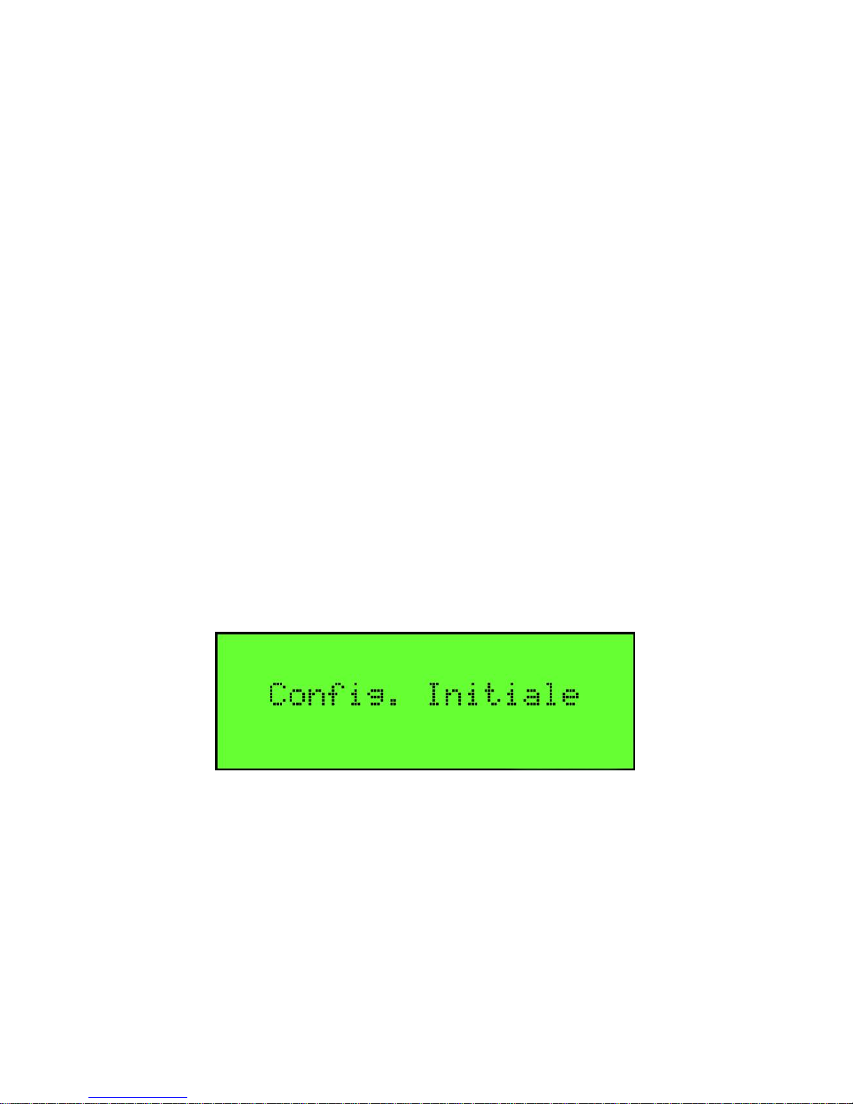
Step 4) Press ON/OFF button once. The FT555F will show the
Initial System Setup screen shown below;
Step 5) Complete the Initial System Setup following the setup
instructions on page 7.
Page 27
FloTech FT555F Automatic Overfill System Tester
FT555F Truck Tester 10784PA REV C Page 7
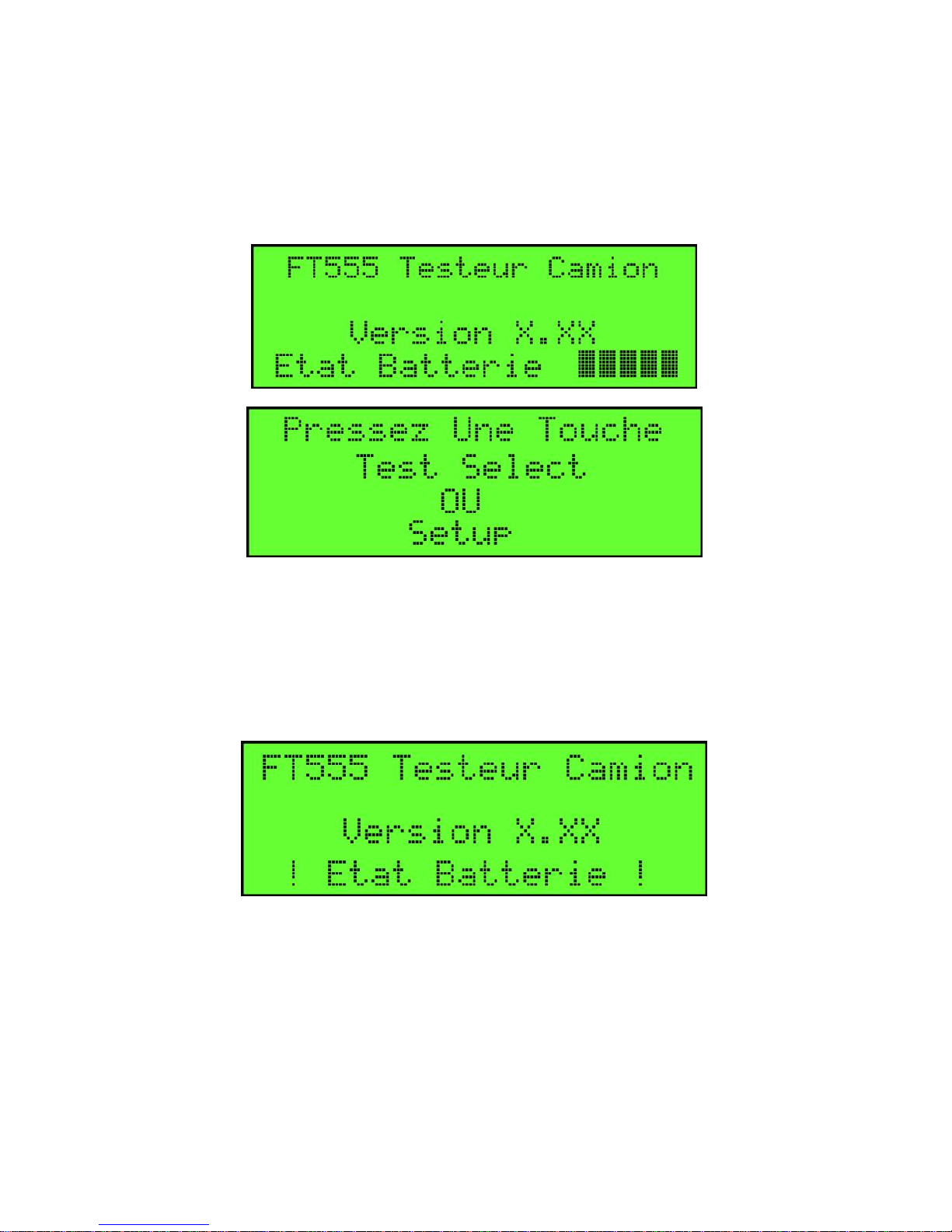
Welcome Screen
After completing the Initial System Setup the welcome screen will
be displayed. This screen will be displayed every time the FT555F
Automatic Tester is turned on.
The Welcome Screen shows the version software the FT555F is
running and the battery health status in bars. 5 bars represent full
battery capacity. If 2 or less bars are displayed, a warning beep will
sound and a warning message will flash for a few seconds.
Batteries should be changed at your next convenience.
Power ON/OFF
Press the ON/OFF button once to turn the tester on. Push the
button again to turn the tester off. The tester has a display back
light for dark conditions. After turning on the tester, press and
hold the ON/OFF button for 2 seconds and the back light will turn
on. Press and hold again for 2 seconds and the back light will go
off.
Page 28
FloTech FT555F Automatic Overfill System Tester
Page 8 10784PA REV C FT555F Truck Tester
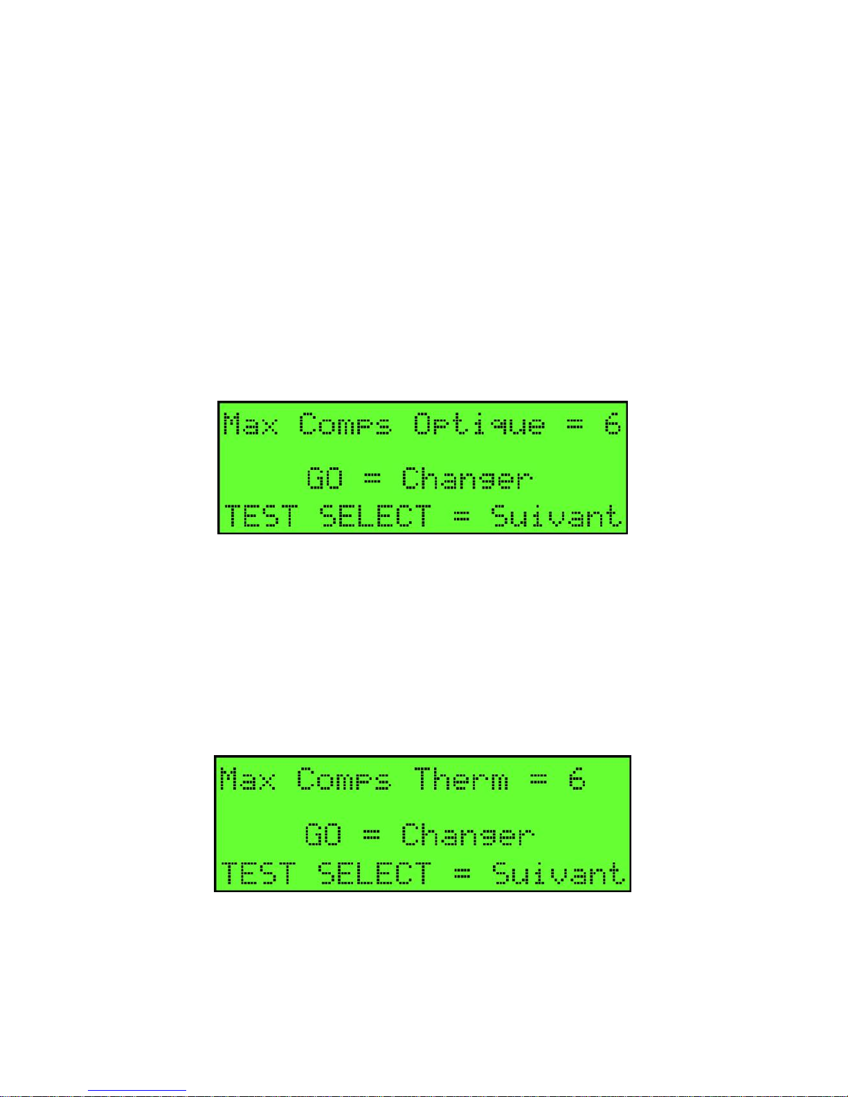
Setup Instructions
At the “Press Key” screen, pressing the SETUP key will enter the
setup mode. The first option will be:
MAX OPTIC COMPS = #
Press the GO button to toggle between 6 and 8 maximum number
of compartments. Generally the USA has a maximum of 6
compartments signals per one socket and Canada or European
regions will have a maximum of 8. Once the correct Maximum
Compartments count is showing, press TEST SELECT button to
move to the next SETUP screen.
MAX THERM COMPS = #
Press the GO button to toggle between 6 and 8 maximum number
of compartments. Generally the USA has a maximum of 6
compartments signals per one socket and Canada or European
regions will have a maximum of 8. Once the correct Maximum
Compartments count is showing, press TEST SELECT button to
move to the next SETUP screen.
Page 29
FloTech FT555F Automatic Overfill System Tester
FT555F Truck Tester 10784PA REV C Page 9
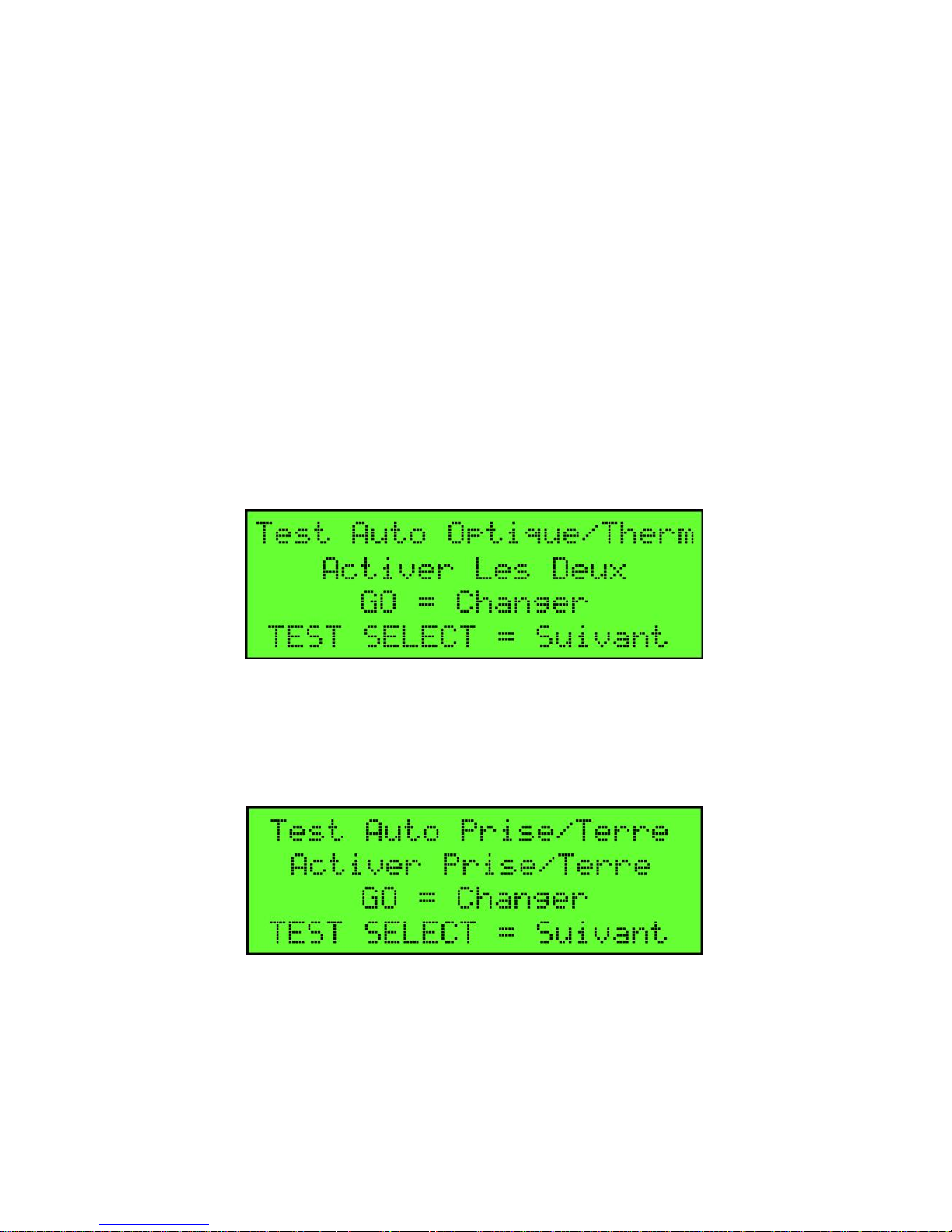
AutoTest Optic/Therm
This screen will enable or disable the Optic or Thermistor tests
when performing an automatic test of the trailer overfill system.
This configuration is only for the automatic testing mode. All four
tests are available in the manual test selection.
Some regions may not have a need to test optic or thermistor type
systems as none are found in that region. Example, trailers in
California do not have Thermistor sockets so there is no need to
perform the Thermistor test. In this case the Optic test would be
enabled.
Press the “GO” button to choose between “Enable BOTH”,
“Enable OPTIC” or “Enable THERM” Press the “TEST
SELECT” button to move to the next screen.
Auto Test Ground Bolt
Press the “GO” button to ENABLE or DISABLE the ground bolt
test during the automatic testing. PRESS “TEST SELECT” button
to move to the next screen.
Page 30
FloTech FT555F Automatic Overfill System Tester
Page 10 10784PA REV C FT555F Truck Tester
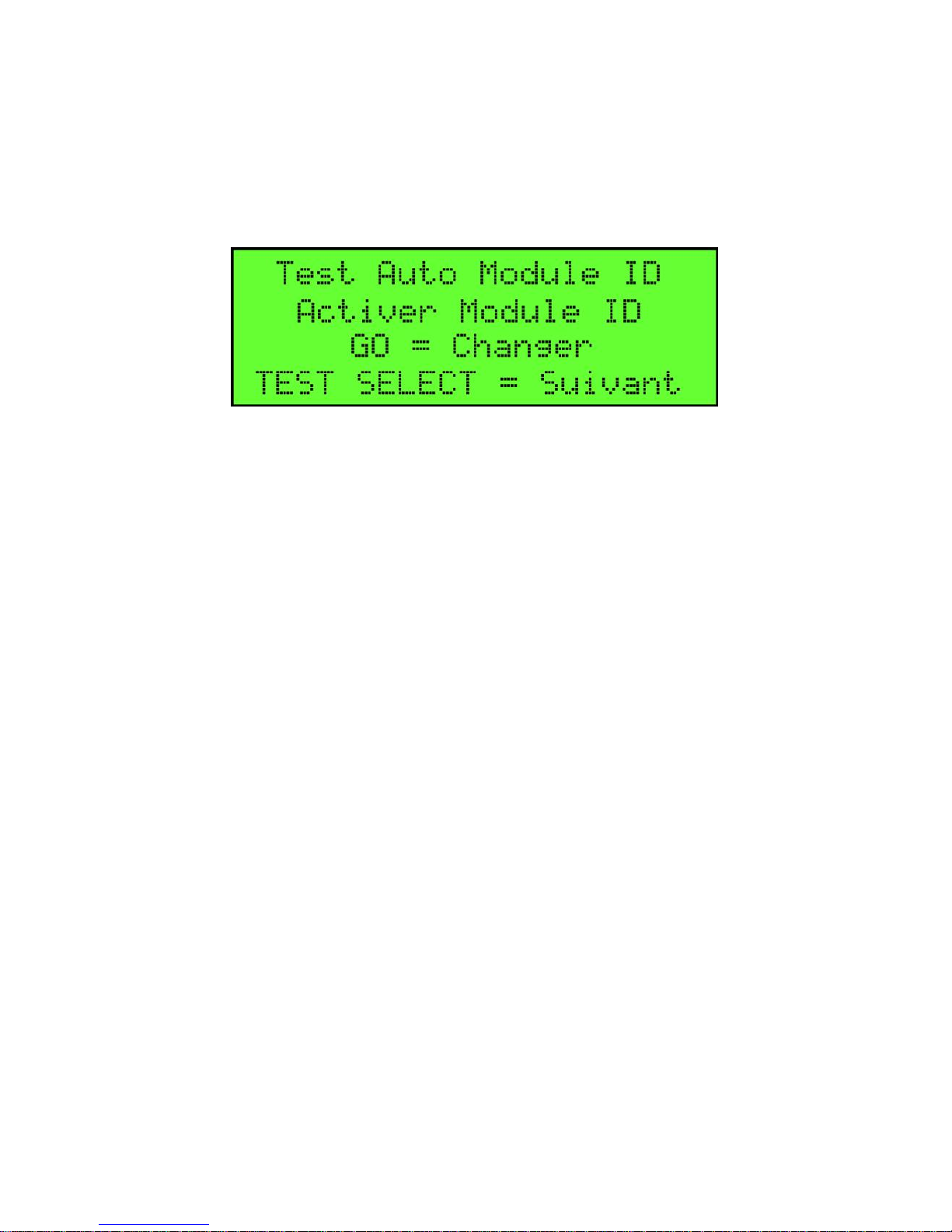
Auto Test Truck ID Module
Press the “GO” button to ENABLE or DISABLE the Truck ID
Module test during the automatic testing. PRESS “TEST
SELECT” button to exit the SETUP mode and return you to the
“PRESS KEY TEST SELECT” screen.
SELECTING TEST OPTION
When at the “Press Key” screen, each time the TEST SELECT
button is pressed the tester will cycle through each of the five
available testing modes.
AUTOMATIC TEST
OPTIC TEST
THERMISTOR TEST
GROUND BOLT TEST
TRAILER ID MODULE TEST
PERFORMING AUTOMATIC TEST
FUCTION
This test option will automatically test all of the available test
options previously enabled in the setup procedure above, and
report the findings in a PASS / FAIL screen.
Step 1) Move the J-Slot thumb screws to the correct holes to match
the type of socket to be connected. Follow the “O” and “T”
markings on the plug body.
Step 2) Connect the FT555F Automatic Tester to the trailer socket.
Page 31
FloTech FT555F Automatic Overfill System Tester
FT555F Truck Tester 10784PA REV C Page
11
Step 3) Press the ON/OFF button to turn on the FT555F Automatic
Tester. When “Press Key” screen appears press “TEST SELECT”
button one time so the “Automatic Test” screen appears.
Step 4) Press the “GO” button to start the test. Follow the prompts
listed in the display screen.
Step 5) Move the J slot screws to match the J-Slot configuration of
the optic socket.
Step 6) Connect the tester to the optic socket.
Step 7) Press go button to start the test.
Next the tester will instruct you to connect to the Thermistor
socket.
Step 8) Move the J-Slot Screws to match the configuration of the
Thermistor socket.
Step 9) Connect the tester to the socket and press the go button to
start the test.
The tester will automatically test the ground bolt and TIM module
if these options are enabled in the set up screen.
Page 32
FloTech FT555F Automatic Overfill System Tester
Page 12 10784PA REV C FT555F Truck Tester
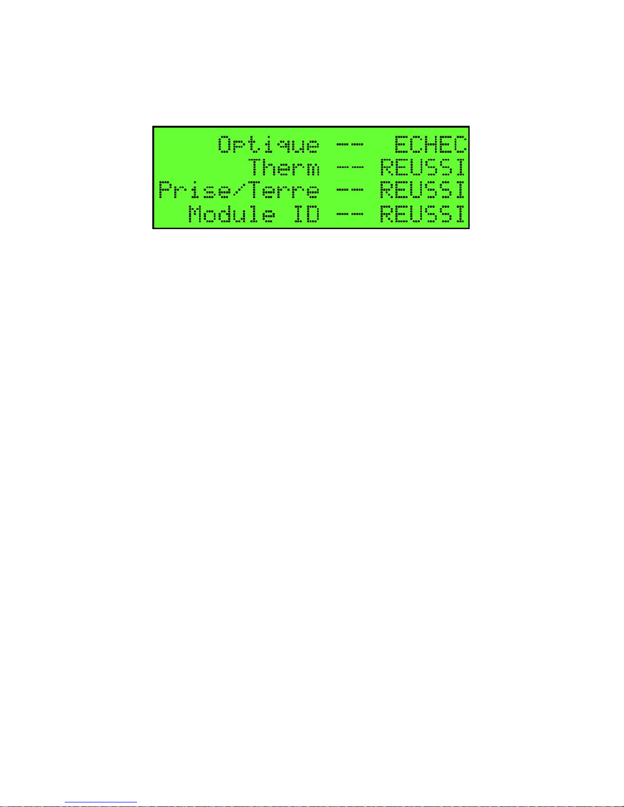
When the test is complete the Screen will display the PASS / FAIL
status of each test performed.
Step 10) Press the “TEST SELECT” button to move on to a new
test, press “GO” to restart the test, or press the “ON/OFF” button
to turn the tester off.
OPTIC TEST
This test will test the API Optic signal from the trailer mounted
sensors or onboard monitor and report a Pass/ Fail.
OPERATION NOTE:
This test will also report the number of good sensors IF THE
SENSORS ARE WIRED DIRECTLY TO THE SOCKET AND
NO ONBOARD MONITOR IS USED. Should your trailer have
an onboard monitor, the tester will test the Onboard Monitor as
if it were a single sensor. The status of sensor connected to an
Onboard Monitor does not pass through the monitor to the
socket.
Step 1) Move the J-Slot thumb screws to the correct holes to match
the type of socket to be connected. Follow the “O” and “T”
markings on the plug body.
Step 2) Connect the FT555F Automatic Tester to the trailer socket.
Step 3) Press the ON/OFF button to turn on the FT555F Automatic
Tester. When “Press Key” screen appears press “TEST SELECT”
button two times so the “Optic Test” screen appears.
Page 33
FloTech FT555F Automatic Overfill System Tester
FT555F Truck Tester 10784PA REV C Page
13
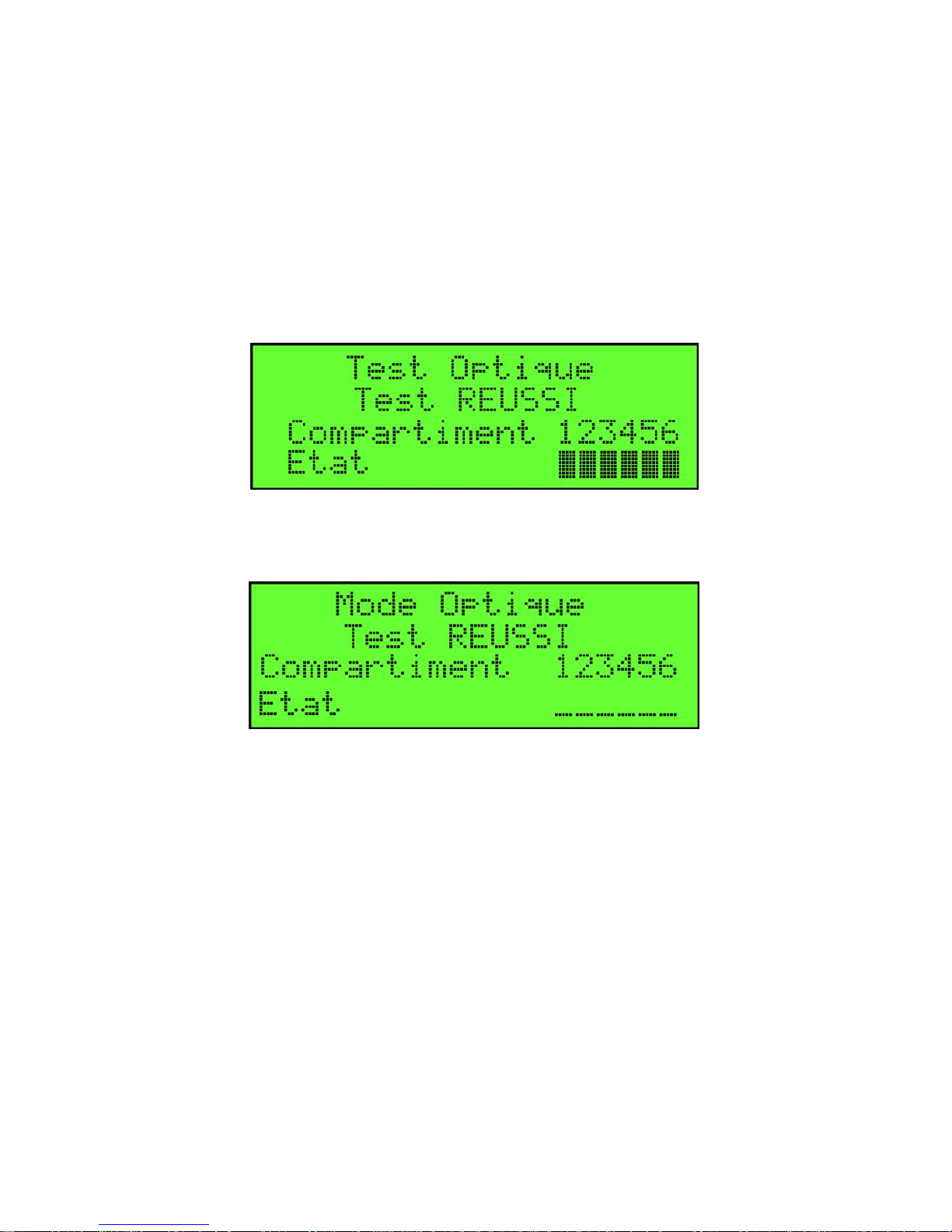
Step 4) Press the “GO” button to start the test. When the test is
complete the screen will display the PASS / FAIL status and a
wet/dry status for each of the compartments enabled during the
setup. A square under the number indicates a dry sensor or a dash
under the number indicates a wet or missing sensor. If connected
to an Onboard Monitor dashed lines will show and no black bars.
Step 5) Press the “TEST SELECT” button to move on to a new
test, press “GO” to restart the test, or press the “ON/OFF” button
to turn the tester off.
Optic pass when connected to sensors is shown above. A black
square will light for each good sensor.
Optic pass when connected to an onboard monitor will show
dashes for sensor status. Onboard monitors do not have a
diagnostic connection to the rack monitor and do not pass the
number of good sensors through the onboard monitor to the socket.
Page 34
FloTech FT555F Automatic Overfill System Tester
Page 14 10784PA REV C FT555F Truck Tester
THERMISTOR TEST
This test will test the API Thermistor signal from the trailer
mounted sensors or onboard monitor and report a Pass/ Fail.
OPERATION NOTE:
This tester is not compatible with the old style analog “green or
silver tipped sensors. These devices require the FT510 tester.
Step 1) Move the J-Slot thumb screws to the correct holes to match
the type of socket to be connected. Follow the “O” and “T”
markings on the plug body.
Step 2) Connect the FT555F Automatic Tester to the trailer socket.
Step 3) Press the ON/OFF button to turn on the FT555F Automatic
Tester. When “Press Key” screen appears press “TEST SELECT”
button three times so the “Thermistor Test” screen appears.
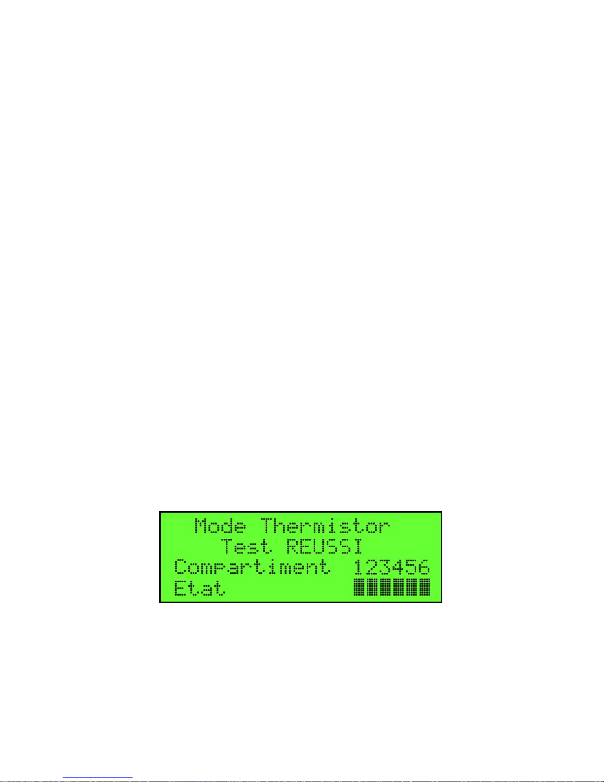
Step 4) Press the “GO” button to start the test. When the test is
complete the screen will display the PASS / FAIL status and a
wet/dry status for each of the compartments enabled during the
setup. A square under the number indicates a dry sensor or a dash
under the number indicates a wet or missing sensor. If connected to
an Onboard Monitor, dashed lines will show and no black bars.
Step 5) Press the “TEST SELECT” button to move on to a new
test, press “GO” to restart the test, or press the “ON/OFF” button
to turn the tester off.
Page 35
FloTech FT555F Automatic Overfill System Tester
FT555F Truck Tester 10784PA REV C Page
15
GROUND BOLT TEST
This test will test the Ground Bolt using the forward and reverse
test to confirm proper operation of the diode inside the ground bolt.
The tester will report a Pass/ Fail.
Step 1) Move the J-Slot thumb screws to the correct holes to match
the type of socket to be connected. Follow the “O” and “T”
markings on the plug body.
Step 2) Connect the FT555F Automatic Tester to the trailer socket.
Step 3) Press the ON/OFF button to turn on the FT555F Automatic
Tester. When “Press Key” screen appears press “TEST SELECT”
button four times so the “Ground Bolt Test” screen appears.
Step 4) Press the “GO” button to start the test. When the test is
complete the screen will display the PASS / FAIL status.
Step 5) Press the TEST SELECT” button to move on to a new test,
press “GO” to restart the test, or press the “ON/OFF” button to
turn the tester off.
Page 36
FloTech FT555F Automatic Overfill System Tester
Page 16 10784PA REV C FT555F Truck Tester
TRAILER ID MODULE TEST
This test will test the Trailer ID Module and report the 12 digit
serial number stored inside the ID module. If there is no trailer ID
module or the test fails the screen will show “TIM not found”
Step 1) Move the J-Slot thumb screws to the correct holes to match
the type of socket to be connected. Follow the “O” and “T”
markings on the plug body.
Step 2) Connect the FT555F Automatic Tester to the trailer socket.
Step 3) Press the ON/OFF button to turn on the FT555F Automatic
Tester. When “Press Key” screen appears press “TEST SELECT”
button five times so the “Trailer ID Module Test” screen appears.
Step 4) Press the “GO” button to start the test. When the test is
complete the screen will report the 12 digit serial number or show
“TIM not found”.
Step 5) Press the TEST SELECT” button to move on to a new test,
press “GO” to restart the test, or press the “ON/OFF” button to
turn the tester off.
Page 37
FloTech FT555F Automatic Overfill System Tester
FT555F Truck Tester 10784PA REV C Page
17
OPTIC AND THERMISTOR WET TEST
NOTE: THE WET TEST FUNCTION IS INTENDED TO BE
USED ON WORKING SYSTEMS. IF THE SYSTEM HAS A
PROBLEM IT MUST BE REPAIRED BEFORE WET
TESTING.
Step 1) Move the J-Slot thumb screws to the correct holes to match
the type of socket to be connected. Follow the “O” and “T”
markings on the plug body.
Step 2) Connect the FT555F Automatic Tester to the trailer socket.
Step 3) Press the ON/OFF button to turn on the FT555F Automatic
Tester. When “Press Key” screen appears press “TEST SELECT”
button a few times until the “Optic Test” or “Thermistor Test”
screen appears, depending on the socket the tester is connected to.
Step 4) Press “WET TEST” button to begin the wet test.
Page 38
FloTech FT555F Automatic Overfill System Tester
Page 18 10784PA REV C FT555F Truck Tester
Step 5) The FT555F will repeatedly test for the presence of any
wet sensors connected to the socket.
Step 6) Dip test a compartment and listen for a beep. The display
will also indicate the presence of a wet sensor.
Step 7) Continue testing each compartment.
Step 8) Stop the wet test by pressing any key.
NOTE: IF THE TESTER DOES NOT SEE ANY SENSORS
OR IS NOT CONNECTED, IT WILL DISPLAY THE
ABOVE SCREEN UNTIL IT SEES A SENSOR OR THE
TEST IS STOPPED.
Page 39

FloTech FT555F Automatic Overfill System Tester
FT555F Truck Tester 10784PA REV C Page
19
CAUTION:
The FT555F is not certified as suitable for use in a Class I
Division 1 hazardous location. You should avoid use in
explosive or flammable atmospheres.
Troubleshooting:
A. Should the FT555F fail to start or shut down during use,
check the battery indicator on the welcome screen and or
replace the batteries.
B. Should the FT555F appear to freeze, remove the batteries
to force the unit to power down. Reinstall the batteries and
begin test procedure. By removing the batteries you will
force the FT555F to restart back to the welcome screen.
Technical Support Hotline
(877) 582-3569
Contact the FloTech Technical Support Hotline for help:
Troubleshooting overfill systems.
Verifying defective components
To request an RGA for defective FloTech products under
warranty.
 Loading...