

Flotec FPSC1725X Owner's Manual
© 2011 FP579 (6/17/2011)
FPSC1725X
OWNER’S MANUAL
Submersible Utility Pump
NOTICE D’UTILISATION
Pompe submersible à usage
général
MANUAL DEL USUARIO
Bomba sumergible de uso general
Installation/Operation/Parts
For further operating, installation, or
maintenance assistance:
Call 1-800-365-6832
English . . . . . . . . . . . . . . . Pages 2-6
Installation/Fonctionnement/Pièces
Pour plus de renseignements
concernant l’utilisation,
l’installation ou l’entretien,
Composer le
1 (800) 365-6832
Français . . . . . . . . . . . . Pages 7-11
Instalación/Operación/Piezas
Para mayor información sobre el
funcionamiento, instalación o
mantenimiento de la bomba:
Llame al 1-800-365-6832
Español . . . . . . . . . . .Paginas 12-16
293 Wright Street, Delavan, WI 53115
Phone: 1-800-365-6832
Fax: 1-800-526-3757
Web Site: FlotecWater.com
READ AND FOLLOW
SAFETY INSTRUCTIONS!
This is the safety alert symbol. When you see this
symbol on your pump or in this manual, look for
one of the following signal words and be alert to the
potential for personal injury.
warns about hazards that will cause serious
personal injury, death or major property damage if ignored.
warns about hazards that can cause serious
personal injury, death or major property damage if
ignored.
warns about hazards that will or can cause
minor personal injury or property damage if ignored.
The label NOTICE indicates special instructions which
are important but not related to hazards.
Carefully read and follow all safety instructions in this
manual and on pump.
Keep safety labels in good condition.
Replace missing or damaged safety labels.
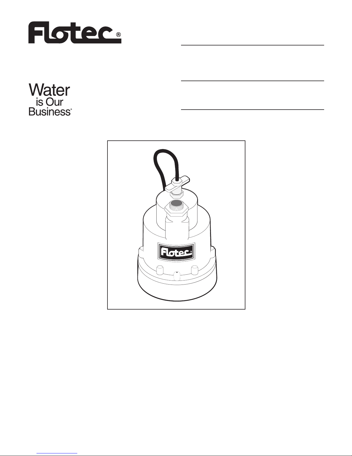
DESCRIPTION
This Submersible Utility Pump is designed for draining
water from basement floors, stock tanks, window wells,
boats, flat roofs and cisterns. Unit is equipped with a
3-prong grounding-type power cord. Shaded-pole motor
is oil filled and sealed for cooler operation. Sleeve bearings on the motor shaft never need lubrication.
Automatic reset thermal protection.
NOTICE: This unit is not designed for applications involv-
ing salt water or brine! Use with salt water or brine will
void warranty.
SPECIFICATIONS
Power supply required...............................120V, 60 HZ.
Motor duty...................................................continuous*
Liquid Temp. Range................. Less Than 120° F (50° C)
Individual Branch Circuit Required (min.).........15 Amps
Pump Discharge............................................1-1/4" NPT
Adapter...............................................3/4" Garden Hose
NOTICE: For continuous operation, the pump must be
submerged to prevent motor overheating.
Risk of fire or explosion. Do not use in
explosive atmospheres. Pump water only with this
pump.
PERFORMANCE
ELECTRICAL & SWITCH
SPECIFICATIONS
Discharge Feet of Head
0 5 10152025
GPH 1320 1170 1020 810 510 0
Safety 2
For parts or assistance, call Flotec Customer Service at 1-800-365-6832
Motor Individual Branch
Full Load Circuit Required
Motor HP Amps (Amps)
1/4 5.6 15

For parts or assistance, call Flotec Customer Service at 1-800-365-6832
General Information / Installation 3
GENERAL SAFETY INFORMATION
Electrically powered utility pumps normally give many
years of trouble-free service when correctly installed,
maintained, and used. See the “Troubleshooting Chart”
in this manual for information about common utility
pump problems and remedies. For more information,
see your retailer, or call Flotec customer service at
1-800-365-6832.
1. Know the pump application, limitations, and poten-
tial hazards.
2. Do not use in water where fish are present.
3. Disconnect the power before servicing.
4. Release all pressure within the system before servic-
ing any component.
5. Drain all water from the system before servicing.
6. Secure the discharge line before starting the pump.
An unsecured discharge line will whip, possibly
causing personal injury and/or property damage.
7. Check hoses for weak or worn condition before each
use. Making certain all connections are secure.
8. Periodically inspect the pump and system compo-
nents. Keep free of debris and foreign objects.
Perform routine maintenance as required.
9. Provide a means of pressure relief for pumps whose
discharge line can be shut-off or obstructed.
10.Personal Safety:
a. Wear safety glasses at all times when working
with the pumps.
b. Keep work area clean, uncluttered and properly
lighted – replace all unused tools and equipment.
c. Keep visitors at a safe distance from the work
area.
d. Make the workshop child-proof – with padlocks,
master switches, and by removing starter keys.
11.When wiring an electrically driven pump, follow all
of the electrical and safety codes that apply.
12.This equipment is only for use on 120 volt (single
phase) and is equipped with an approved 3-conductor cord and 3-prong, grounding-type plug.
Hazardous voltage. Can shock, burn or
cause death. To reduce the risk of electric shock,
pull the plug before servicing. This pump has not
been investigated for use in swimming pool areas.
The pump is supplied with a grounding conductor
and grounding-type attachment plug. Be sure it is
connected only to a properly grounded groundingtype receptacle.
Where a 2-prong wall receptacle is encountered, it
must be replaced with properly grounded 3-prong
receptacle installed in accordance with the codes
and ordinances that apply.
Do not walk on wet area until all power has been
turned off. If the shut-off box is in the basement,
call the electric company or hydro authority to shut-
off the service to house, or call your local fire
department for instructions. Failure to follow this
warning can result in a fatal electrical shock.
Do not lift the pump by the power cord.
13.All wiring should be performed by a qualified
electrician.
14.Make certain the power source conforms to the
requirements of your equipment.
15. Protect the electrical cord from sharp objects, hot surfaces, oil, and chemicals. Avoid kinking the cord.
Replace or repair damaged or worn cords immediately.
16.Do not touch an operating motor. Motors are
designed to operate at high temperatures.
17.Do not handle the pump or pump motor, or change
fuses with wet hands or when standing on wet or
damp surface, or in water.
INSTALLATION
1. Set the pump on a hard surface in at least 2” of
water.
2. Connect the discharge line with the fittings provided.
3. The pump should not be installed on clay, dirt, mud
or sand surfaces. Although the pump will usually
pass small particles suspended in water, clean the
area to be pumped of small stones and gravel which
could clog the pump.
NOTICE: Grass, mud, sand or pea gravel can clog the
pump and reduce it’s performance. Keep the pump inlet
screen clean.
4. To reduce motor noise and vibrations when using rigid
pipe, a short length of rubber hose (e.g. radiator hose)
can be connected into the discharge line near the
pump using suitable clamps.
5. Power Supply: Pump is designed for 120 V., 60 Hz.,
operation and requires a minimum 15 amp. individual branch circuit. Pump is supplied with a 3-wire
cord with grounding-type plug.
Hazardous voltage. Can shock, burn or
cause death. Pump should always be electrically
grounded to a suitable electrical ground such as a
grounded water pipe or a properly grounded metallic
raceway, or ground wire system. Do not cut off
round ground pin.
6. If the pump discharge line is exposed to an outside
sub-freezing atmosphere, the line exposed must be
installed so any water remaining in pipe will drain to
the outfall by gravity. Failure to do this can cause
water trapped in the discharge line to freeze which
could result in damage to pump.
7. Check the operation of pump by observing through
one complete cycle.
Risk of flooding. Failure to make this
operational check may lead to improper operation,
premature failure, and flooding.
For parts or assistance, call Flotec Customer Service at 1-800-365-6832
Operation 4
OPERATION
Hazardous voltage. Can shock, burn or
cause death. Do not handle a pump or pump motor
with wet hands or when standing on wet or damp surface, or in water.
1. The shaft seal depends on water for lubrication and
for cooling. Do not operate the pump unless it is submerged in water. The seal may be damaged if allowed
to run dry.
2. The pump will not remove all water. During manual
operation the pump will pump down to within 1/8”
of the pumping surface. If the optional switch is used,
the final water level is determined by placement of
the switch.
NOTICE: For continuous operation, the pump must
be submerged to prevent the motor from overheating.
A fully submerged pump is preferred for proper cooling when a pump runs continuously.
AIRLOCKS
When a pump airlocks, it runs but does not move any
water. An airlock will cause the pump to overheat and
fail. This pump has a built in anti-airlock hole. See the
exploded view on the repair parts page for the location
of the hole. Leakage from the anti-airlock hole is normal.
If you suspect an airlock, unplug the pump, clean out the
anti-airlock hole with a paper clip or a piece of wire,
and restart the pump.
Troubleshooting
SYMPTOM PROBABLE CAUSE(S) CORRECTIVE ACTION
Pump won’t start or run. Pump is not plugged in. Check and see if pump is plugged in to a proper outlet.
Blown fuse or breaker. If blown, replace with fuse of proper size or reset breaker.
Low line voltage. If voltage under recommended minimum, check size of
wiring from main switch on property. If OK, contact power
company or hydro authority.
Defective motor. Replace pump.
Pump starts and stops. Motor is overheating. Discharge or intake are obstructed. Pump is in too
shallow of water.
Pump operates but Restricted discharge Remove pump and clean pump and piping.
delivers little or no water. (obstacle or ice in piping).
Restricted intake. Remove the pump and clean out the intake screen.
Low line voltage. If voltage under recommended minimum, check size of
wiring from main switch on property. If OK, contact power
company or hydro authority.
Worn or plugged impeller. Replace pump.
Anti-airlock hole is plugged. Turn off the pump, clean out the anti-airlock hole, and
restart the pump.
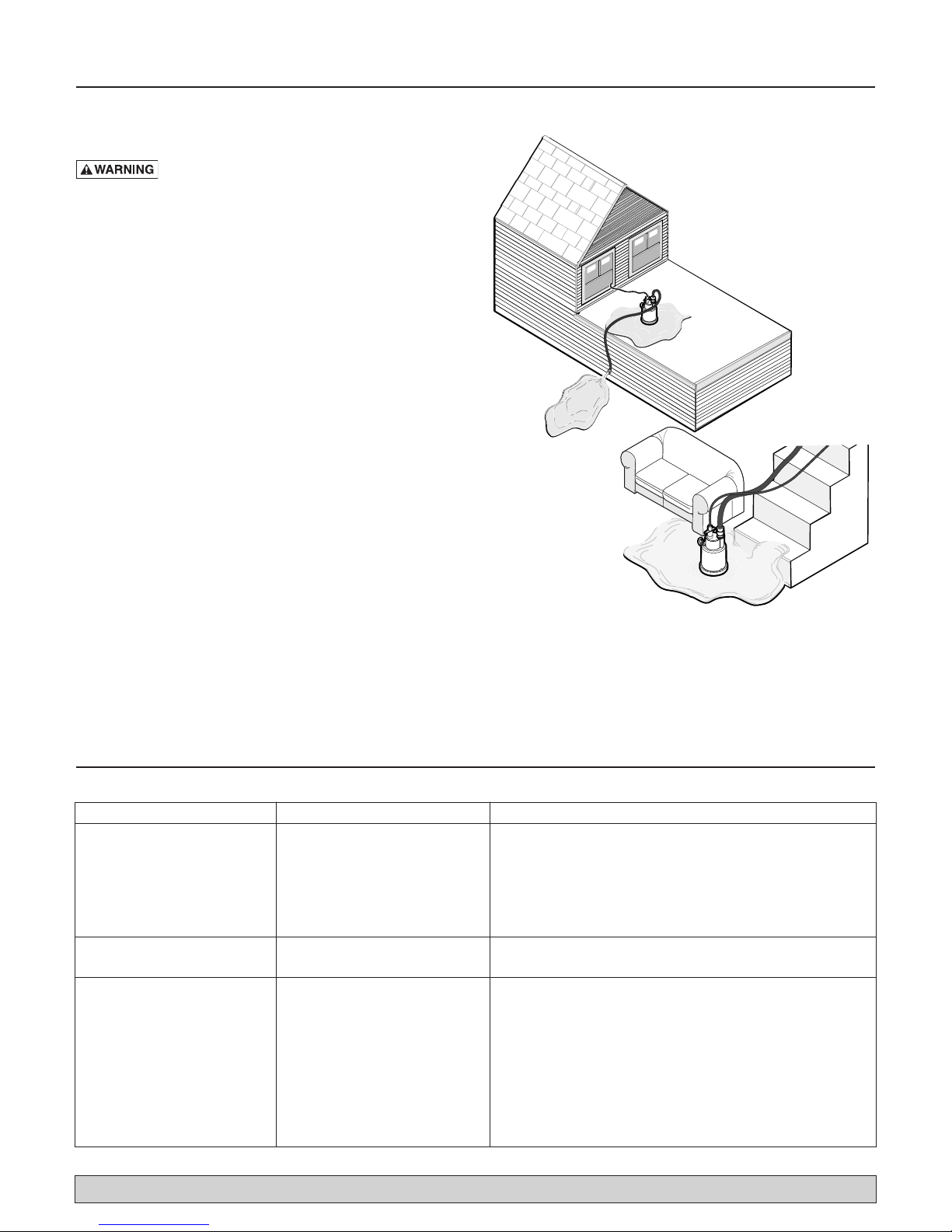
Roofs
3696 0500 NEW
.3
Basements
.3
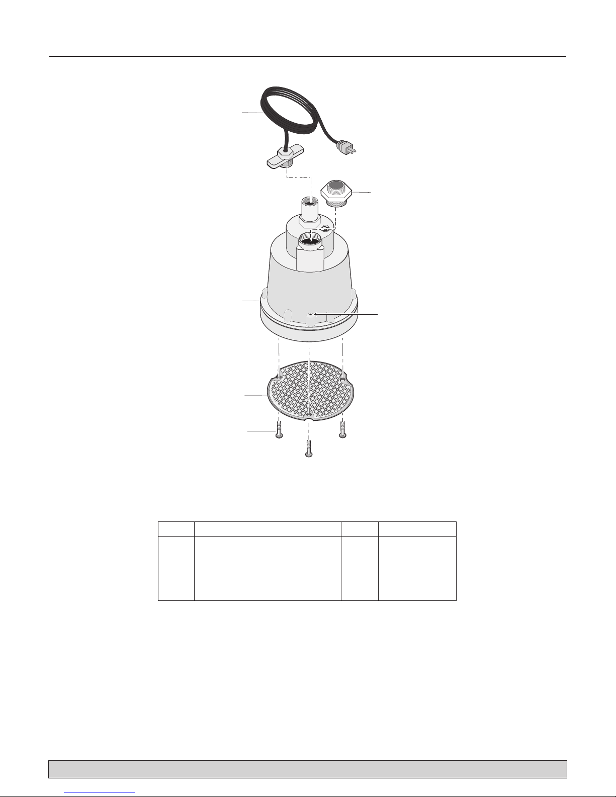
Repair Parts 5
4
1
2
3
5
Anti-airlock Hole
For parts or assistance, call Flotec Customer Service at 1-800-365-6832
REPAIR PARTS
Key Part Description Qty. FPSC1725X-02
1 Power Cord 1 PS117-54-TSU
2 Adapter 1 007-031
3 Motor Assembly 1 **
4 Inlet Screen 1 667-016
5 Screws, Screen 3 670-793
** If the motor fails, replace the entire pump.
 Loading...