

Flotec FPDC30 Owner's Manual
OWNER’S MANUAL
Battery Backup System
NOTICE D’UTILISATION
Système de secours à batterie
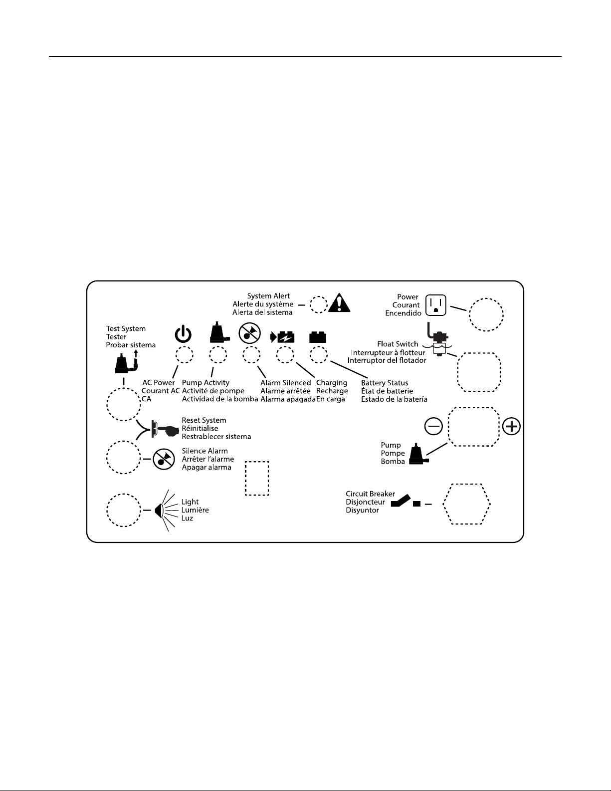
Device ID Key
MANUAL DEL USUARIO
Sistema de batería de respaldo
Test System
Tester
Probar sistema
System Alert
Alerte du système
Alerta del sistema
AC Power
Courant AC
CA
Pump Activity
Activité de pompe
Actividad de la bomba
Power
Reset System
Alarm Silenced
Courant
Réinitialise
Encendido
Alarme arrêtée
Restrablecer sistema
Alarma apagada
Interrupteur à otteur
Float Switch
Interruptor del otador
Silence Alarm
Charging
Arrêter l’alarme
Recharge
Apagar alarma
En carga
Battery Status
État de batterie
Estado de la batería
Light
Lumière
Luz
Pump
Pompe
Bomba
Circuit Breaker
Disjoncteur
Disyuntor
+
FPDC30
Installation/Operation/Parts
For further operating, installation,
or maintenance assistance:
Installation/Fonctionnement/Pièces
Pour plus de renseignements
concernant l’utilisation,
l’installation ou l’entretien,
Call 800-365-6832
English ........................... Pages 2-16
©2014 FP979 (04/08/14)
Composer le
(800) 365-6832
Français .................... Pages 17-31
Instalación/Operación/Piezas
Para mayor información sobre el
funcionamiento, instalación o
mantenimiento de la bomba:
Llame al 800-365-6832
Español ..................... Paginas 32-46

Safety 2
Important Safety Instructions
SAVE THESE INSTRUCTIONS - This manual contains
important instructions that should be followed during
installation, operation, and maintenance of the product.
This is the safety alert symbol. When you see this
symbol on your pump or in this manual, look for one of
the following signal words and be alert to the potential
for personal injury!
indicates a hazard which, if not avoided,
will result in death or serious injury.
indicates a hazard which, if not avoided,
can result in death or serious injury.
indicates a hazard which, if not avoided,
can or may result in minor or moderate injury.
NOTICE addresses practices not related to personal injury.
Carefully read and follow all safety instructions in this
manual and on pump.
Keep safety labels in good condition. Replace missing or
damaged safety labels.
To avoid risk of serious bodily injury due to electrical
shock or burns and property damage due to flooding,
read the safety instructions carefully before installing
pump.
Battery acid is corrosive. Do not spill on
skin, clothing, or battery charger. Wear eye and head
protection when working with battery. Connect and
disconnect DC output terminals only after removing the
charger from the AC outlet. Never allow the DC
terminals to touch each other.
Hazardous Voltage. Can cause severe or
fatal electrical shock. Do not plug in or unplug battery
charger while standing on a wet floor or in water. Be sure
one hand is free when plugging in or unplugging charger.
If basement floor is wet, disconnect power to basement
before walking on floor.
Risk of flooding. Do not run pump dry. To
do so will damage seals and can cause leaking and
property damage.
Follow local and/or national plumbing and electrical
codes when installing the system. A ground fault circuit
interrupter (GFCI) is recommended for use on any
electrical appliance submerged in water.
Use this system only for backup sump pump duty in a
residential application. It is not designed as a primary
sump pump.
Do not lift pump by electrical cord.
Risk of electrical shock. Do not lift the
pump by the electrical cord; lift pump only by the
discharge pipe, lifting ring or handle on the pump. Lifting
by the cord can damage the cord.
Pump clear water only with this pump.
Pump is permanently lubricated at the factory. Do not try
to lubricate it!
Keep battery charger and battery box off of the floor and
in a dry, cool, well ventilated area.
NOTICE: If a Carbon Monoxide (CO) sensor is installed,
it must be at least 15 feet away from battery charger
in order to avoid nuisance CO alarms. Please refer
to your CO detector’s installation guidelines for more
information.
To avoid danger of fire or explosion, keep sparks and
flame (pilot light) away from battery.
Maximum vertical pumping distance is 15 feet (4.6M) for
Model FPDC30.
Make sure sump is clear of debris. Debris can damage
the pump which can result in flooding.
GENERAL INFORMATION
The battery backup sump system is not a substitute for
your primary sump pump. It is designed to temporarily
backup your primary sump pump during a power outage
or other problem which prevents normal operation of
the primary pump. Do not use this system to pump
flammable liquids or chemicals. Pump clear water only
with this pump.
Keep the battery charger dry and protected from damage.
This system is designed to work with a deep cycle sealed
maintenance free lead-acid AGM battery. It will also
work with a flooded lead acid battery. Gell and Sealed
flooded lead acid batteries are not recommended. In
an emergency (such as an extended power outage)
which depletes the system deep cycle battery, your
automobile battery may be temporarily substituted. Be
sure to replace the system deep cycle battery as soon
as possible. Use of an automobile battery instead of a
deep cycle battery in this system will significantly reduce
the system’s total performance. Automobile batteries
are not designed for this type of application and will be
quickly ruined by the repeated charge/discharge cycling.
NOTICE: This system is not designed for applications
involving salt water, brine, or where fish may be present!
Use with these will void warranty.
California Proposition 65 Warning
This product and related accessories contain
chemicals known to the State of California to cause
cancer, birth defects or other reproductive harm.

Installation 3
BASIC TOOLS AND PARTS NEEDED
(Purchase Separately)
Channel locks or large adjustable pliers
Tape measure
Socket wrench or 5/16” nut driver
Side cutters
Hacksaw (to cut PVC pipe)
Medium size pliers
Slotted screwdriver
Phillips head screwdriver
Pencil or marker
PTFE pipe thread sealant tape
PVC glue (solvent weld)
PVC pipe cleaner
Cloth towel
Plastic fittings
Check valve(s) - 1 or 2 depending on installation
38-120 Ampere-Hour Storage or Deep Cycle Battery
Required Battery Capacity:
For best results, use the following AGM Storage Batteries:
Gal/Charge
Part Amp-Hour
BAT40 40 4,800 5 Hours
BAT75 75 11,500 11.5 Hours
• Unit equipped with dual battery capability
• Maximum amp-hour: 120
NOTICE: The charger will not fully charge batteries with
excessive amp hour ratings without resetting system.
at 10’
Approx Run
Time
BATTERY BACKUP SYSTEM (BBU)
INSTALLATION AND OPERATION
NOTICE:
• Install this system during a time when the primary
pump will not be needed. Gather all supplies before
starting. Read all warnings and installation steps
before you start.
• Be prepared for water to leak from the coupling or
piping when disassembling or cutting the discharge
pipe. Protect system components, tools and supplies
from getting wet. Dry any work areas that get wet.
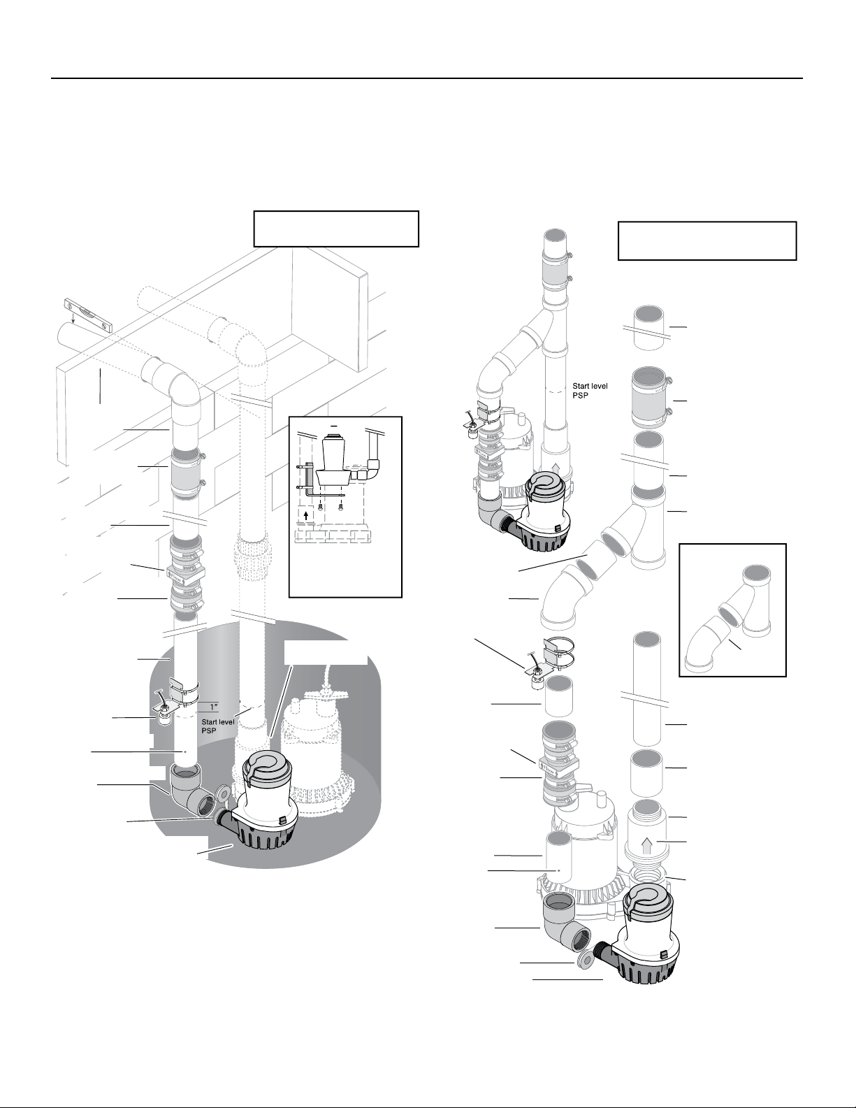
NOTICE: Study pages 4-6 to determine which installation
method will be best for you. The “Separate Discharge”
(Figure 2, Page 4), installation is recommended.
NOTICE: Check your local codes and ordinances
regarding waste water disposal (especially when running
the pump discharge outside the house) before you start.
The installation must conform to all legal requirements.
If possible, install the BBU so that the discharge goes
directly outdoors (separate discharge pipe from the
primary sump pump discharge pipe). If this is not a
practical option, see the “Common Discharge” (Figure 3,
Page 4) option.
NOTICE: For ALL installations, once the installation is
complete, run both the primary sump pump and the BBU
through at least one complete cycle to make sure that
everything operates correctly.
Personal injury and flood hazard. Do not
turn the pump on until all the fittings are glued and the
glue has dried. Loose fittings can explode off of pipes
and cause personal injury and flooding.
Risk of electrical shock. At the circuit breaker
or fuse box, turn off the electrical power to the sump
pump before beginning this installation.
Setup
1. Locate the high water level in your sump pit (the
water level at which the existing (primary) sump
pump starts - see Figure 1). Turn off power to pump
and mark this point on the discharge pipe with a
pencil or marker.
2. Drain the sump pit as far as possible without running
the pump dry. Do this by:
A. Piggyback switch: Unplug the pump and switch
from the outlet, then unplug the pump from the
piggyback switch. Reset the circuit breaker or
reinstall the fuse and plug the pump directly into
the outlet. The pump will start. Drain the pit and
unplug the pump. OR
b. No piggyback switch: Reset the circuit breaker
or reinstall the fuse and use a non-conducting
broom handle or stick to raise the float switch;
the pump should start. Drain the pit and then
release the switch.
3. When the pit has drained, turn off (open) the circuit
breaker or remove the fuse again to avoid electrical
shock while working on the installation.
Figure 1: Mark pipe at ‘start’ water level
Installation 4
“Separate Discharge”
“Common Discharge”
NO
c
as sho
kup
System. Chec
AWA
T
T
assembled
Both check v
must be installed
on the pump side
of the
6783 0313a
NOTICE:
Check Valve Flapper(s) must swing AWAY and flow arrow(s) must point
AWAY from pump being protected.
The water level when the switch shuts off must be above the BBU
pump intake.
* Supplied with the Battery Backup System.
Items in italics must be purchased separately.
Slope DOWN
to outlet
1-1/2” PVC Upper
Discharge Pipe
(cut to fit)
U74-68 Hose and
Clamp Assembly
(Purchase Separately)
1-1/2” PVC Riser Pipe
(cut to fit)
Flow Arrow; Must point
AWAY from Pump
being Protected
FP0026-10
Check Valve
(Purchase
Separately)
Lower Discharge Pipe
1-1/2” PVC Pipe
(cut to fit)
Not to scale.
Wiring omitted for clarity.
Sill
Floor
Joist
If the sump is small,
hang the BBU from
the Primary discharge
pipe on an angle bracket.
Primary Sump Pump
Check Valve
TICE: In this installation, if the Primary Sump Pump (PSP) does not have a
heck valve installed below the wye, you MUST install a check valve for the PSP
wn. This prevents backflow of water into the sump from the Battery Bac
k Valve Flapper(s) must swing AWAY and flow arrow(s) must point
Y from the pump being protected.
he water level when the switch shuts off must be above the BBU pump intake.
ypical installation,
.
alves
wye.
Optional 1-1/2”
PVC Pipe (cut to fit)
45º Slip Elbow
Battery Backup
Switch*
FLOW
Not to scale.
Wiring omitted for clarity.
Supplied with the Battery Backup System.
*
Items in italics must be purchased separately
1-1/2” PVC Upper
Discharge Pipe
(cut to fit)
U74-68 Hose and
Clamp Assembly
(Purchase Separately)
1-1/2” PVC Riser Pipe
(cut to fit)
45 degree Slip Wye
AlternateWye/Elbow
Setup
45º Slip Street
Elbow
Battery Backup
Switch*
Drill 1/8” Anti-Airlock
Hole
1-1/4” FNPTx1-1/2” Slip
Elbow*
PTFE pipe thread
sealant tape on all
threaded joints
Battery Back Up
Sump Pump*
FLOW
Figure 2: Typical installation with separate
discharge pipes.
6782 0313a
1-1/2” PVC Pipe
(cut to fit)
Flow Arrow; Must point
AWAY from Pump
being Protected
FP0026-10
Check Valve
(Purchase
Separately)
Lower Drischarge Pipe
1-1/2” PVC Pipe
(cut to fit)
Drill 1/8”
Anti-Airlock Hole
1-1/4” FNPTx1-1/2”
Slip Elbow*
PTFE pipe thread
sealant tape on all
threaded joints
Battery Back Up
Sump Pump*
FLOW
Primary Pump
Discharge Pipe
(cut to fit)
Thread to Slip
Adapter
Primary Pump
Check Valve
Flow Arrow; Must point
AWAY from Pump
being Protected
Primary Sump Pump
Discharge Port
Figure 3: Typical installation with common
discharge pipe.

Installation 5
INSTALLATION (Typical): Separate Discharge
Risk of electrical shock. Can shock, burn, or
kill. Unplug the primary sump pump before beginning this
procedure.
NOTICE: Allow for overlap when cutting piping and run a
trial (dry) fitting before you glue.
1. Use PTFE pipe thread sealant tape on male ends of
discharge pipe. Thread the 1-1/4” x 1-1/2” elbow
(supplied) onto the discharge. When tight, the elbow
must point up.
2. If possible, install the Battery Backup Unit (BBU) on
the floor of the sump; be sure that the two pumps do
not touch each other and do not interfere with switch
operation.
NOTICE: If debris or gravel is present in the bottom of
the sump pit that could get sucked up into the pump, set
both the primary sump pump and the BBU up on bricks
or cinder blocks to prevent clogging.
3. If the sump is too small to allow both pumps to sit on
the bottom of the sump, install an angle bracket on the
primary sump pump’s discharge pipe with stainless steel
hose clamps. Mount the backup pump on the angle
bracket. See Figure 1, “Separate Discharge”.
4. Cut a piece of 1-1/2” PVC pipe to reach from the backup
pump discharge elbow to about one (1) foot above the
basement floor. This is the lower discharge pipe.
5. To prevent airlocking the pump during operation, drill a
1/8” hole in the lower discharge pipe about 2” above the
bottom of the pipe (below floor level).
6. Install FP0026-10 check valve (purchase separately)
on the upper end of the pipe. Tighten the hose clamps
securely. BE SURE that the flow arrows point UP (away
from the BBU). If they point down, the valve will not
pass water and the pump will not work.
7. Cut a short length of 1-1/2” PVC pipe for a riser pipe and
clamp it into the top of the check valve.
8. Install a U74-68 Hose and Clamp Assembly on the top
of the riser pipe. For 1-1/2” pipe, remove and discard
the short piece of 1-1/4” hose in the Hose and Clamp
Assembly. Leave the hose clamps loose and slide the
Assembly down below the top of the riser pipe.
9. Determine where you want the discharge to exit the
basement. At that point, drill the necessary holes (large
enough to have clearance for a 1-1/2” pipe) to allow you
to run the discharge pipe from above the sump to the
outdoors.
10. Install the horizontal discharge pipe. Install a 90° elbow
on the inside end but do not glue.
11. Cut another short piece of 1-1/2” PVC for the Upper
Discharge Pipe to run from the top of the riser pipe up to
the 90° elbow. Be sure to allow enough overlap for the
glue joint in the elbow.
12. Do a trial fit with NO GLUE, installing the 1-1/2” upper
discharge pipe in the 90° elbow and the upper discharge
pipe in the vertical end of the 90° elbow. The upper
discharge pipe should just fit between the riser pipe and
the elbow.
13.
Whenever using PVC primer and PVC cement, follow
the glue manufacturer’s instructions.
14. Make sure that the BBU will clear the primary sump
pump and its switch. If there isn’t room for both pumps
to sit on the floor of the sump, the BBU will have to be
raised (depending on your particular situation).
15. Clean, prime and glue the upper discharge pipe into the
90º elbow. When the glue has set, slide the Hose and
Clamp Assembly up to cover the joint and tighten all the
hose clamps.
16. Install the Battery Backup Switch as shown, 1” above
start water level of primary pump. Fasten it to the pipe
with cable ties.
17. Tape the pump cord to the riser pipe so that the plug
cannot fall into the sump.
18. Go to “BBU WIRING AND SETUP” (Page 8) for wiring
instructions.
19. Once all wiring is complete, fill your pit with water
and verify that the PSP removes the water and the BBU
doesn’t run. Then, unplug your PSP and refill your pit
with water. Verify that the BBU pump removes the water.
20. Make sure that the power is on to both pumps, and your
system is ready to use.
Risk of fire and chemical inhalation.

Installation 6
INSTALLATION (Typical): Common Discharge
Risk of electrical shock. Can shock, burn, or
kill. Unplug the primary sump pump before beginning this
procedure.
NOTICE: Allow for over lap when cutting piping and run a
trial (dry) fitting before you glue.
NOTICE: If there is no check valve in the primary sump
pump’s discharge, you will need to install one. You must also
install one in the BBU’s discharge pipe (Figure 3, Page 4). Make
sure that the check valve flow arrow points AWAY from the
pump it is protecting.
1. Use PTFE pipe thread sealant tape on male ends of
discharge pipe. Thread the 1-1/4” x 1-1/2” elbow
(supplied) onto the discharge. When tight, the elbow
must point up.
2. If possible, position the BBU on the floor of the sump;
be sure that the two pumps do not touch each other and
do not interfere with switch operation.
NOTICE: If debris or gravel is present in the bottom of
the sump pit that could get sucked up into the pump, set
both the primary sump pump and the BBU up on bricks
or cinder blocks to prevent clogging.
3. If the sump is too small to allow both pumps to sit on the
bottom of the sump, find a raised position that doesn’t
interfere with the PSP switch.
4. Cut a piece of 1-1/2” PVC pipe to reach from the backup
pump discharge elbow to about one (1) foot above the
basement floor. This is the lower discharge pipe.
5. To prevent airlocking the pump during operation, drill a
1/8” hole in the lower discharge pipe about 2” above the
bottom of the pipe (below floor level).
6. Install FP0026-10 check valve (purchase separately)
on the upper end of the pipe. Tighten the hose clamps
securely. BE SURE that the flow arrows point UP (away
from the backup pump). If they point down, the valve
will not pass water and the pump will not work.
7. Cut the discharge pipe for the primary sump pump (PSP)
above the union and check valve (if any). Make this cut
about 18” above the top of the BBU’s riser pipe with the
backup pump sitting as installed.
8. If the PSP does not have a check valve installed in the
discharge pipe, install one now.
9. Cut a length of discharge pipe for the PSP to fit between
the check valve and a 45° slip wye. Be sure to allow for
the overlap needed for gluing joints.
10. Install the 45° wye on the PSP’s discharge pipe.
11. Install a 45° elbow on the 1-1/2” BATTERY BACKUP
discharge pipe.
NOTICE: You may need to insert a piece of straight pipe
between the elbow and the wye. If so, use a standard
45° elbow. If you do not need to insert a piece of straight
pipe between the elbow and the wye (elbow goes
directly into the wye), use a 45° slip street ell.
12. Fit the upper discharge pipe to the upper end of the wye.
NOTICE: It is good practice to cut a short length of
pipe to go into the wye and install a union on the pipe.
Continue the discharge pipe from the outlet side of
the union. This will allow easier removal of the system
for cleaning or service. A U74-68 Hose and Clamp
Assembly can be used for this.
13. Make sure that the BBU will clear the primary sump
pump and its switch. If there isn’t room for both pumps
to sit on the floor of the sump, the BBU will have to be
raised (depending on your particular situation).
14. Do a trial assembly to make sure that everything is
going to fit. This may require a helper to assist in holding
everything together while you check the fit without glue.
Mark all joints before gluing.
Risk of fire and chemical inhalation. Follow the
glue manufacturer’s instructions regarding fire hazards and
ventilation when using PVC solvents, primer, and cement.
15. Take all the pipe apart, clean all joints, and then
reassemble the system, gluing it with PVC primer and
glue.
16. Install the Battery Backup Switch as shown, 1” above
start water level of primary pump. Fasten it to the pipe
with the cable ties provided.
17. Tape the pump cord to the riser pipe so that the plug
cannot fall into the sump.
18. Go to “BBU WIRING AND SETUP” (Page 8) for wiring
instructions.
19. Once all wiring is complete, fill your pit with water
and verify that the PSP removes the water and the BBU
doesn’t run. Then, unplug your PSP and refill your pit
with water. Verify that the BBU pump removes the water.
20. Make sure that the power is on to both pumps, and your
system is ready to use.

Battery Requirements 7
BATTERY REQUIREMENTS
Hazardous electric current. Can cause
severe burns and start a fire if the battery terminals are
short circuited. Install the battery in the battery case. To
prevent accidental shorting across battery terminals,
close and latch the battery case securely. Do not leave
the battery uncovered.
Do not allow children to play around the battery
backup system installation.
The performance of your backup sump pump depends on
the battery used with it for power. We recommend using
our BAT40 or BAT75. You can also use a group 24M or
27M Deep Cycle battery. They will provide acceptable
performance and will stand up well to long periods of
little or no use.
This system is designed to work with either a sealed
lead-acid AGM battery or a flooded lead-acid battery.
Use of a true Gell Cell (often confused for AGM) or a
standard automotive battery with this charger is not
recommended. An automotive battery may require
charging after only 1-2 hours of continuous use, and the
repeated charging cycles may cause early plate failure in
the battery.
Use only lead-acid batteries. This unit is not designed to
use with Li-Ion, NiMh, NiCAD, Liquid Polymer, etc.
Use only the recommended battery or one of the same
type and size so it will fit in the battery box (maximum
size: 13” long x 7” wide x 10” tall (330.2mm x 177.8mm
x 254mm) including terminals) and supply enough
voltage for full performance.
BATTERY MAINTENANCE
Severe burn hazard. An acid-filled standard
lead-acid battery contains sulfuric acid. Avoid contact with
skin, eyes or clothing.
NOTICE: To protect the battery case from chipping and
gouging, do not let the battery sit on a concrete floor.
Install the battery on a shelf or protective pad (plywood,
2x4s, etc.). Always install the battery in a dry location
that is protected from flooding.
Pre-Qualification Test – 1 and 2
Charger is charging at a very low level to try to bring a
dead battery back to life. If the battery is taking too long,
try resetting the charger once or twice (push the ‘SYSTEM
TEST’ and ‘SILENCE ALARM’ buttons together to reset the
charger).
Special Features:
The charger is equipped with reverse battery, short
circuit, and “runaway charge” protection.
Possible Problems and Remedies
1. Wrong Battery Voltage
Reconnect charger to a 12 volt battery.
2. Reversed Battery Connections
Check all connections. The negative (black) on the
battery must connect to the negative (black) on
the charger, and the positive (red) on the battery
must connect to the positive (red) on the charger.
Reversing the battery connections will cause the
‘SYSTEM ALERT’ and ‘SILENCED AUDIBLE ALARM’
LEDs to flash.
3. Thermal Runaway Condition
“Thermal Runaway” is the technical term for the
condition of the battery when some (or all) of the
cells have deteriorated to the point that they won’t
take a charge. In this case, replace the battery.
4. Charge Time Monitor – 1 and 2
Battery took too long to complete its charge. The
“Charge Time Monitor” will shut down the charger
after 84 hours of continuous charging.
Possible causes are:
A) Pump ran for a long period of time during
charging, or
B) Battery is too large for the charger (including
several batteries connected in a parallel circuit).
Excessive Battery Drain
Pump may have run for a very long time, discharging the
battery. In this case:
1. If 115VAC power is OFF, the charger shuts down
until the power comes back on, but the pump will
run as long as the battery charge lasts. You may need
to replace the battery afterwards.
2. If 115VAC power is ON, the charger/controller
continues to try to charge the battery at a charging
rate of .5 AH until the battery charge is more
than 20%, at which point the charger will resume
charging at a rate of 2 AH.
3. If the pump is running and the AC power is on, you
may need to stop the pump to allow the battery to
charge.
Follow the battery manufacturer’s recommendations for
maintenance and safe use of the battery.
Wiring • Setup 8
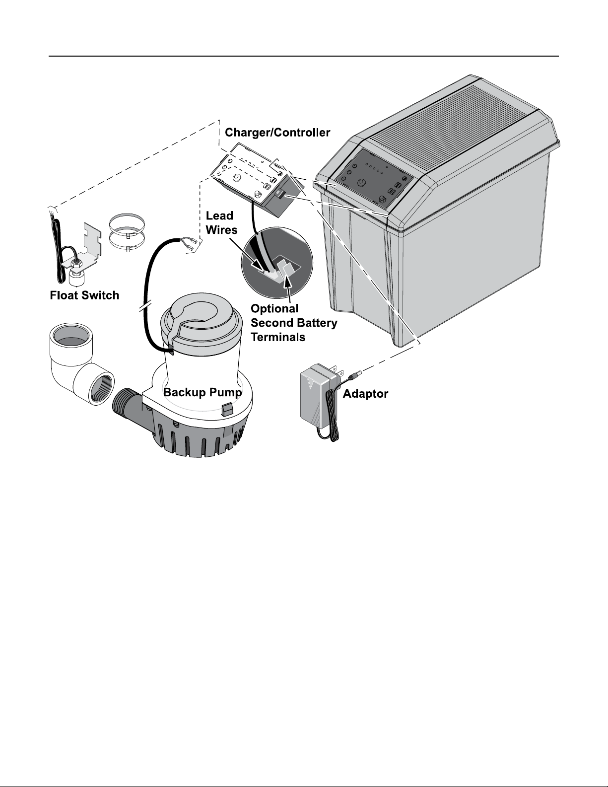
BBU WIRING AND SETUP
1. Connect the positive (+) charger/controller lead
wire (red) to the positive (+) battery terminal (red).
Connect the negative (–) charger/controller lead
wire (black) to the negative (–) terminal (black) on
the battery. If you are using two batteries, use the
set of optional terminals and connect the second
battery. Use lead wires (not included) to connect
the positive (+) charger/controller terminal to the
positive (+) battery terminal and the negative (–)
charger/controller terminal to the negative (–) battery
terminal.
2. The backup pump leads are polarity sensitive;
connect the positive pump lead to the terminal
labeled Pump ‘+’ and the negative pump lead to the
terminal labeled Pump ‘–’.
NOTICE: If the leads are reversed, the pump will run
backward and not pump water.
3. The float switch leads are not polarity sensitive;
connect the float switch leads to the ‘Float Switch’
tabs on the charger/controller.
4. Test the float and the pump by lifting and holding
the float. The system alert LED will blink while
the float is up. The ‘PUMP STATUS’ LED will light
continuously and the buzzer will beep steadily. The
pump should start after 3 seconds. If the pump does
not run, check all the connections and remake them
as necessary.
5. To stop the pump, lower the float; after 25 seconds
the pump should stop, the ‘PUMP STATUS’ LED
should flash, and the buzzer should beep.
6. With the pump operating, test the ‘SILENCE ALARM’
button; hold for one second; release. The ‘ALARM
SILENCED’ LED should illuminate and the buzzer
should stop sounding. To reset the buzzer (allow it to
sound) and extinguish the ‘ALARM SILENCED’ LED,
press the ‘SILENCE ALARM’ button again for one
second.
Depress the ‘TEST SYSTEM’ button; hold it for one
second; release. The ‘PUMP STATUS’ LED should stop
flashing.
Wiring • Setup 9
NOTICE: During normal operation, the flashing
‘PUMP STATUS’ LED indicates that the pump has
run in your absence.
1. Press and hold ‘TEST SYSTEM’ button. All LEDs will
light up, pump will run and buzzer will sound.
Release the button and LEDs should go off, pump
should stop, buzzer should stop.
2. The ‘BATTERY STATUS’ LED indicates the battery
capacity when the A.C. power is off.
A. Continuously ON - the battery voltage is above
10.9 Volts Direct Current (10.9VDC) and
capacity is above 20%.
B. Slow Beep/Slow LED Flash - the battery’s
capacity is between 0 and 20%.
LED Display and Control Buttons
C. Fast Beep/Fast LED Flash - the battery is severely
discharged. The battery will continue to charge
(as long as the 115V AC power to the charger is
on) at the rate of .5 AH until the battery’s charge
is above 20%.
When the first warning occurs (slow beep/slow
flash), you will have approximately 2 hours (or less)
of pump operation left. The actual time of operation
will depend on the condition of the battery and may
be as little as 15 minutes.
4. Connect the Power Supply cable (supplied) to the
Charger/Controller’s Power Input jack.
NOTICE: When the unit is first plugged in, or when it first receives power from the battery, the ‘BATTERY STATUS’
LED will flash for 3 seconds.
NOTICE: To activate any Control Button, press and hold it for 1 second.

Virtual Water Assistant Setup 10
Battery Backup Internet Connection and
Alerts Configuration
Before setting up the Virtual Water Assistant (VWA), make
sure your Battery Backup Unit - FPDC30 is installed correctly, refer to Owner’s Manual for instruction. Make sure
the primary pump and battery backup unit has power.
Verify the system is operational by pressing the ‘TEST
SYSTEM’ button and observing the test sequence.
1. Find an open network connection on your internet
router or other hard-wired connection. Rotate the
antennae up on the gateway.
NOTICE: We recommend the use of an uninterrupted
power supply for your internet modem, home router
and the gateway power supply.
2. Using the supplied 1 meter Ethernet cable (or longer
cable if necessary), connect the gateway to an open
network port.
3. Connect the gateway power supply to a 115 VAC
outlet, plug into the back of the gateway.
• The LED will blink red for a few seconds.
• When the LED becomes solid green or solid
green with an occasional blink your gateway is
connected to the VWA servers.
If not, refer to Gateway Troubleshooting.
4. Once the gateway LED is green, go to the BBU and
verify that the AC power LED is solid green. If not, the
gateway will have to be moved closer to the BBU.
5. Log onto the website www.VirtualWaterAssistant.com
• Select “Sign Up”
• Follow the online instructions and enter the
required personal information to create a user
account. The Alerts will use the e-mail addresses
and phone numbers entered here.
• Enter the Unique Device ID Key included with
the FPDC30 - located on BBU case and manual
cover.
6. Test installation by clicking the “Test” icon on the
web page and verify the unit has run the test.
7. Using the drop down menu configure the desired
method of Alerts you want to receive (Text or E-mail).
8. Alerts can be tested by activating the pump with the
float switch.

Virtual Water Assistant Setup 11
Gateway Troubleshooting
IF GATEWAY LED LIGHT IS NOT GREEN (GREEN, SLOW BLINK) FIRST TRY TO “POWER CYCLE” THE GATEWAY (UNPLUG THE
POWER CORD, WAIT 15+ SECONDS, THEN RE-APPLY POWER).
Gateway Status
Indicator (LED Color)
Green Power on: gateway connected to servers. OK - Connection complete and operational
Green, quick blink Power on: data traffic to servers. OK - Operating, data is moving between BBU and
Green, slow blink
(1-2 blinks per second)
Red Power on: gateway has no local connection to
Red, slow blink
(1-2 blinks per second)
Off Power off or product fault. Check power source, verify power adapter is
Definition Action Needed
Server
Power on: gateway connected to local router, but
not connected to Internet or servers.
router. The gateway does not "recognize/see" that it
is connected to the router.
Power on: gateway communicating with router, but
router cannot assign Dynamic Host Configuration
Protocol (DHCP) or Domain Name System (DNS) to
gateway.
System is online and scanning for destination/server
(add a network switch inline to help define unit).
Check Ethernet cable connections and/or quality or
cable. Try a different router port. Is the router turned
on.
Router is not permitting the gateway to access the
internet (add a network switch inline to help define
unit).
functioning. Defective gateway.
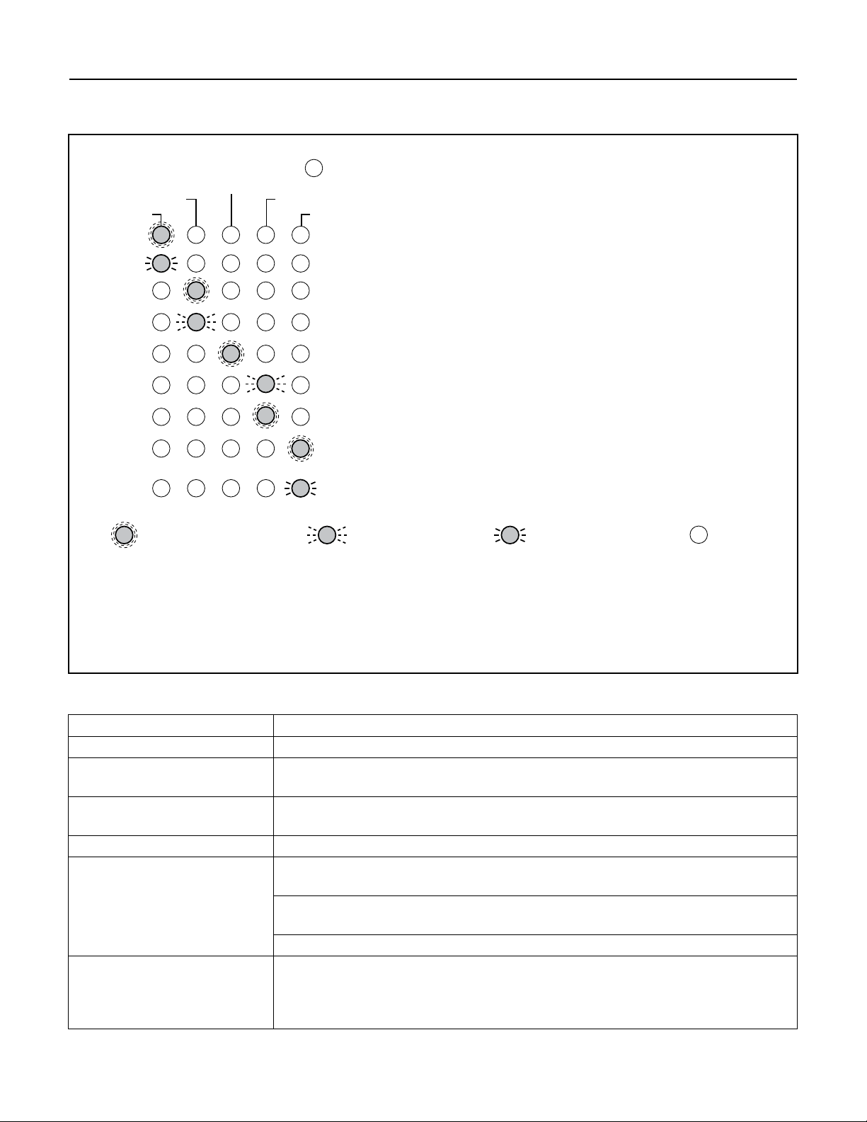
Charger/Controller LED Display 12
LED Operating Code Display
System Operating Condition
6790 0313
TABLE II – Operating Code Displays (LEDs Lighted Continuously or Flashing)
SYSTEM ALERT
ALARM SILENCED
PUMP ACTIVITY
AC POWER
CHARGING
BATTERY STATUS
Indicates 115V AC Power is connected / Unit online
Indicates 115V AC Power is connected / Unit offline
Indicates Pump is running (continuous LED)
Indicates Fast flashing LED: Pump has run
Indicates Audible alarm is switched off
Indicates Fast flashing LED: Battery pre-qualification test is running
Indicates Battery is charging normally
Indicates Continuous LED: battery charge is above 20%,
system is maintaining charge
Indicates Slow flashing LED: battery charge is below 20%
= =
LED is ON Continuously
=
LED is Flashing (Fast)
=
LED is Flashing (Slow)
LED is OFF
NOTICE: All of the situations listed above indicate normal system operation; no action is required.
However, if the BBU pump is running or has run, check the primary pump and actively monitor the
charger status for battery life. Always reset the charger after the pump runs.
During normal system operation, the ‘SYSTEM ALERT’ LED blinks while the float switch is on,
indicating the pump should start within 3 seconds. The “AC POWER” LED is lighted
(solid or blinking) as long as the system is plugged in to an operating AC power circuit.
TABLE III – LED Function Displays (LEDs Lighted Continuously)
Control LED: Continuous Illumination Indicates Normal Operation:
AC Power AC power is present. Unit is online.
Pump Status
Silenced Audible Alarm Audible Alarm has been silenced. Press and release the ‘SILENCE ALARM’ button
Charging
Battery Status A. Continuous ON - the battery voltage is above 10.9 Volts DC and capacity is
System Alert Flashing (in unison with the buzzer) indicates that the charger has entered ‘Failure
The float switch has been activated. The LED remains on (flashing) after the pump
has stopped. Depress the ‘SYSTEM TEST’ button to reset it.
to reset (activate) the audible alarm and turn OFF the LED.
Indicates that the battery is charging – see Table II, above.
above 20%.
B. Slow Beep/Slow LED Flash - the battery’s capacity is below 20%, and voltage is
between 8.2VDC and 10.9VDC.
C. Fast Beep/Fast LED Flash - the battery has been discharged to less than 8.2VDC.
Mode’. Press the ‘SYSTEM TEST’ and ‘SILENCE ALARM’ buttons to reset it.
NOTICE: If the source of the failure is not corrected, the charger will reenter
“Failure Mode”. See Table IV for error code information.
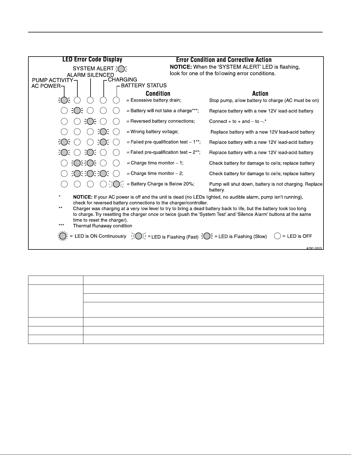
Charger/Controller LED Display 13
TABLE IV – Error Code Displays (LEDs Flashing)
TABLE V – Control Button Functions
Control Button: Result of Pushing Button:
System Test Pump starts and all LEDs light up.
Will reset the ‘PUMP ACTIVITY’ LED.
When pushed with the ‘SILENCE ALARM’ button, the Charger/Controller microprocessor resets
and error code resets.
Silence Alarm Toggle; Prevents the audible alarm sounding. Press and release to reset.
Light Toggles the light on the Charger/Controller on and off.
System Reset Press and release ‘TEST SYSTEM’ and ‘SILENCE ALARM’ to reset system.

Troubleshooting 14
TROUBLESHOOTING - PUMP
Pump won’t run: Check all the wiring connections.
Check for a low or defective battery.
Check that the automatic switch is free to move up and down.
Press the circuit breaker reset button on the control panel.
Motor hums but pump won’t run: Check for low or defective battery.
Pump runs but pumps very little or no water: Make sure a check valve is installed and functioning between the
primary pump discharge and the Battery Backup wye.
Check for an obstruction in the discharge pipe.
The discharge pipe length and/or height exceeds the capacity of the
pump.
Check for a low or defective battery.
The Positive (+) and negative (–) pump wires are reversed.
Disconnect them and reconnect correctly.
Pump cycles too frequently: The check valve located between the discharge of the primary
pump and the Battery Backup wye is not installed or is not
working properly. Install an auxiliary check valve or replace the
existing check valve as required.
 Loading...