

Flotec FP7100, FP7100H, FP7110, FP7110T, FP7110TH Owner's Manual
...
OWNER’S MANUAL
Pre-Charged Pressure and
Horizontal Tanks and Fittings
©2006 FP490 (Rev. 8/25/06)
P.O. Box 342, Delavan, WI 53115
Phone:
1-800-365-6832
Fax:
1-800-526-3757
E-Mail:
info@flotecwater.com
Web Site:
http://www.flotecwater.com
MODELS
FP7100
FP7100H
FP7110
FP7110T
FP7110TH
FP7120
FP7125
FP7130
FP7135
Installation/Operation/Parts
For further operating,
installation, or maintenance
assistance:
Call 1-800-365-6832
English..................... Pages 2-8
®
Safety 2
READ AND FOLLOW
SAFETY INSTRUCTIONS!
This is the safety alert symbol. When you see
this symbol on your pump or in this manual,
look for one of the following signal words and be
alert to the potential for personal injury.
warns about hazards that will cause
serious personal injury, death or major property
damage if ignored.
warns about hazards that can cause
serious personal injury, death or major property
damage if ignored.
warns about hazards that will or can
cause minor personal injury or property damage if
ignored.
The label NOTICE indicates special instructions
which are important but not related to hazards.
Carefully read and follow all safety instructions in
this manual and on pump.
Keep safety labels in good condition.
Replace missing or damaged safety labels.
1. Read this manual carefully. Failure to follow
these Instructions could cause serious bodily
injury and/or property damage.
2. Consult installer or licensed plumber for correct
relief valve. Install system according to local
codes.
3. Always test water from well for purity before
using. Check local health department for testing
procedure.
4. Before installing or servicing tank, BE SURE
pump electric power source is disconnected.
Release all water pressure before working on
tank or system. Release air pressure before
removing cover flange.
5. Install relief valve in pump supply line to tank,
as close to tank as possible.
6. BE SURE pump electrical circuit is properly
grounded.
7. Remove bleeder orifices, air volume controls or
other air charging devices in existing system.
8. DO NOT USE tank as a surge suppressor.
Hazardous pressure. To prevent possible serious or fatal injury and/or damage to
equipment, system pressure must be less than 100
pounds per square inch (PSI) (689kPa) under any
circumstances. Failure to follow instruction can
result in tank blowup. If system discharge pressure
can exceed 100 PSI (689kPa), install a relief valve
capable of passing the full pump volume at 100
PSI (689kPa).
Do not allow pump, tank, or piping
system to freeze. Freezing can severely damage
equipment and may lead to tank explosion and
serious injury. Allowing tank to freeze voids tank
warranty.
For parts or assistance, call Flotec Customer Service at 1-800-365-6832
For parts or assistance, call Flotec Customer Service at 1-800-365-6832
General Information 3
GENERAL INFORMATION
Tanks listed below are pre-charged, or filled with
air at the factory, to 40 pounds per square inch
(PSI) (276kPa). When installing tank, set tank pressure according to Chart 1. To do this, bleed air from
or add air to tank through valve on top of tank.
NOTICE: Always set or check tank pre-charge with
NO WATER in tank or water pressure in system. If
you have already pumped water before setting or
checking pre-charge pressure, turn pump off. Open
faucet until there is no more water pressure. Set
pre-charge in tank according to Chart 1, then close
faucet and turn pump back on.
NOTICE: Replace and tighten air valve cap after
pressure is adjusted correctly. Failure to replace air
cap may allow loss of air pressure and lead to tank
waterlogging and bladder failure.
CHART I
(The first number on the pressure switch is the
pump on setting; the second number is the pump
off setting.)
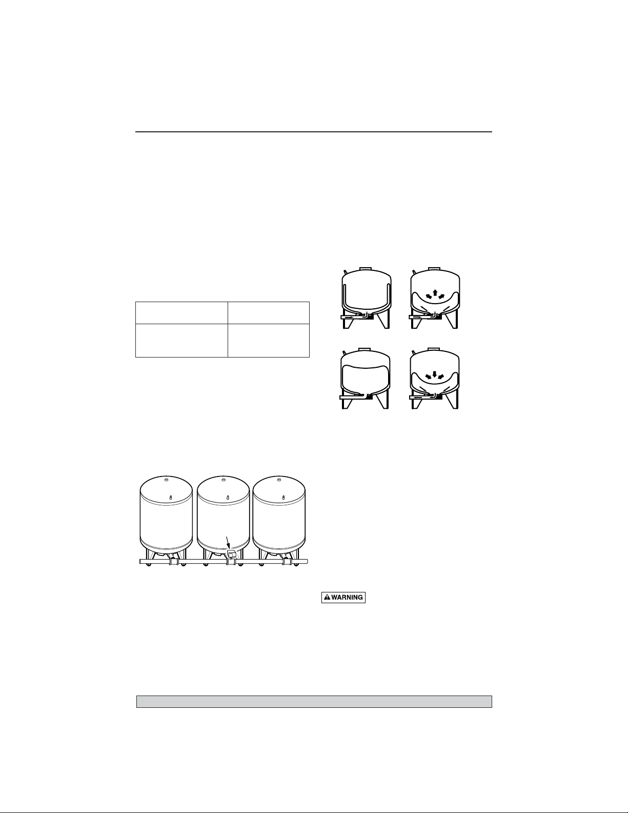
Pre-charged storage tanks can be connected together to increase the drawdown. Drawdown is the
actual amount of usable water available from when
the tank is full to when the pump turns on.
Installing two tanks of same size will double the
drawdown supply, three tanks will triple the drawdown supply, (Figure 1). Locate pressure switch as
shown. Tank and pressure switch cannot be more
than 10’ (3M) apart.
NOTICE: Tank capacity is different than drawdown.
Tank capacity is the actual physical volume of the
sheet metal that makes up the tank.
OPERATING CYCLE (FIGURE 2)
Step 1. Tank nearly empty – air expands filling area
above bladder (Figure A).
Step 2. Water enters tank – air is compressed
above bladder as it fills with water
(Figure B).
Step 3. Pump-up cycle completed – air compressed
to OFF setting of pressure switch (Figure C).
Step 4. Water drawn from tank – compressed tank
air forces water out of bladder (Figure D).
Step 5. Bladder empty – new cycle ready to begin
(Figure A).
Connect discharge pipe from pump to a tee.
Connect one side of tee to tank flange and the
other side of tee to service. Use plastic or steel pipe
as required. To prevent leaks, use Teflon tape or
Plasto-Joint Stik
1
on male threads of all threaded
connections to tank.
STANDARD TANK
REPLACEMENT
When replacing standard tank in a water system
with pre-charged tank, no bleeder orifices or Air
Volume Control (AVC) are required. When sizing a
pre-charged tank to replace a standard tank, the
tanks should have equivilant drawdowns. For
example, model FP7110T precharged tank has a
drawdown of 5.8 gallons (22L) and is equivalent to
a 42 gallon standard tank that has a drawdown of
4.3 gallons (16.3L).
Hazardous voltage and hazardous
pressure. Disconnect all power to pump and bleed
all pressure from system before working on pump,
tank, or piping.
1
Lake Chemical Co., Chicago, Illinois
When Pressure Switch Reduce Tank
Setting Is Precharge (PSI) To
20-40 PSI (138-276 kPa) 18 (124 kPa)
30-50 PSI (207-345 kPa) 28 (193 kPa)
40-60 PSI (276-414 kPa) 38 (262 kPa)
Figure 1
Figure 2
Tanks
AB
CD
WATER
Pressure
switch
To serviceFrom well
909 0993
WATER
WATER
 Loading...