

Flotec FP6121-01, FP6131, FPC6141, FPC6131 Owner's Manual

OWNER’S MANUAL
Above Ground
Swimming Pool Pump
NOTICE D’UTILISATION
Pompe pour piscine hors sole
MANUAL DEL USUARIO
Bomba para piscinas de
natación sobre el suelo
Installation/Operation/Parts
For further operating, installation,
or maintenance assistance:
Call 1-800-365-6832
English . . . . . . . . . . . . . . Pages 2-12
Installation/Fonctionnement/Pièces
Pour plus de renseignements
concernant l’utilisation,
l’installation ou l’entretien,
Composer le
1 (800) 365-6832
Français . . . . . . . . . . . Pages 13-23
Instalación/Operación/Piezas
Para mayor información sobre el
funcionamiento, instalación o
mantenimiento de la bomba:
Llame al 1-800-365-6832
Español . . . . . . . . . . .Paginas 24-34
©2005 FP486 (Rev. 6/15/05)
Mod. FP6121-01, FP6131,
FPC6131, FPC6141
P.O. Box 342, Delavan, WI 53115
Phone:
1-800-365-6832
Fax:
1-800-526-3757
E-Mail:
info@flotecwater.com
Web Site:
http://www.flotecwater.com
®
OVER TIGHTEN
DO NOT
Safety 2
For parts or assistance, call Flotec Customer Service at 1-800-365-6832
FLOTEC SWIMMING POOL PUMP
To avoid unneeded service calls, prevent possible
injuries, and get the most out of your pump, READ THIS
MANUAL CAREFULLY!
The Flotec Above Ground Pool Pump:
• Is designed to circulate water in above ground swimming pools (not for use in spas or inground pools).
• Is an excellent performer; durable, reliable.
IMPORTANT SAFETY
INSTRUCTIONS
Always follow basic safety precautions with this
equipment, including the following.
To reduce the risk of injury, do not permit children to use this product unless they are closely
supervised at all times.
SAVE THESE INSTRUCTIONS
READ AND FOLLOW
SAFETY INSTRUCTIONS!
This is the safety alert symbol. When you see this
symbol on your pump or in this manual, look for
one of the following signal words and be alert to the
potential for personal injury.
warns about hazards that will cause serious
personal injury, death or major property damage if
ignored.
warns about hazards that can cause serious
personal injury, death or major property damage if
ignored.
warns about hazards that will or can cause
minor personal injury or property damage if ignored.
The label NOTICE indicates special instructions which
are important but not related to hazards.
Carefully read and follow all safety instructions in this
manual and on equipment. Keep safety labels in good
condition; replace if missing or damaged.
Incorrectly installed or tested equipment
may fail, causing severe injury or property
damage.
Read and follow instructions in owner's
manual when installing and operating equipment. Have
a trained pool professional perform all pressure tests.
1. Do not connect system to a high pressure or city
water system.
2. Use equipment only in a pool installation.
3. Trapped air in system can cause explosion. BE SURE
all air is out of system before operating or testing
equipment.
Tighten Flotec trap lids to hand tight only.
Water pressure must be less than 25 PSI (7.5 kg/cm
2
).
Water Temperature must be less than 104° F (40° C).
Fire and burn hazard. Modern motors run
at high temperatures. To reduce the risk of fire, do not
allow leaves, debris, or foreign matter to collect around
the pump motor. To avoid burns when handling the
motor, let it cool for 20 minutes before trying to work on
it. An automatic internal cutoff switch protects the motor
from heat damage during operation.

For parts or assistance, call Flotec Customer Service at 1-800-365-6832
Table of Contents 3
Thank you for purchasing a top quality, factory tested pump.
Page
General Safety .....................................................................................................2
Installation ...........................................................................................................4
Electrical..............................................................................................................5
Operation ........................................................................................................6, 7
Pump Service...................................................................................................7, 8
Troubleshooting ...................................................................................................9
Repair Parts .................................................................................................10, 11
Warranty............................................................................................................12
Installation 4
For parts or assistance, call Flotec Customer Service at 1-800-365-6832
For ease of pump/motor removal, install pipe unions on
the suction and discharge pipes close to pump.
Pump mount must:
Be located away from corrosive or flammable liquids.
Have enough ventilation to maintain air temperature at
less than the maximum ambient temperature rating (Max.
Amb.) listed on the motor model plate. If this pump is
installed in an enclosure/pump house, the enclosure
must have adequate ventilation and air circulation to
keep the temperature in the enclosure at or below the
motor’s rated ambient temperature whenever the pump is
running.
Be solid - Level - Rigid - Vibration free. (To reduce vibration and pipe stress, bolt pump to mount.)
Allow pump suction inlet height to be at or below water
level in pool.
Allow use of short, direct suction pipe (To reduce friction
losses).
Allow for gate valves in suction and discharge piping.
Have adequate floor drainage to prevent flooding.
Be protected from flooding.
Allow adequate access for servicing pump and piping.
NOTICE: Use Teflon tape or Plasto-Joint Stik1for making
all threaded connections to the pump. Do not use pipe
dope; pipe dope will cause stress cracking in the pump.
NOTICE: Pump suction and discharge connections have
molded in thread stops. DO NOT try to screw pipe in
beyond these stops. Tighten the pump/trap fittings only as
much as required to insure a tight connection (1-1/2
turns past hand tight is sufficient). Overtightening may
damage the pump trap. Use care when using teflon tape
as friction is reduced considerably; do not overtighten
connections or damage may occur.
Teflon Taping Instructions:
Use only new or clean PVC pipe fittings.
Wrap male pipe threads with one to two layers of Teflon
tape. Cover entire threaded portion of pipe.
Do not overtighten or tighten past thread stop in pump
port!
If leaks occur, remove pipe, clean off old tape, rewrap
with one to two additional layers of tape and remake the
connection.
NOTICE: Support all piping connected with pump!
1
Lake Chemical Co., Chicago, Illinois
Piping:
To avoid strains on the pump, support both suction and
discharge pipes or hoses independently. Place these supports near the pump.
To avoid airlocking, slope suction pipe slightly upward
toward the pump.
NOTICE: To prevent flooding when removing pump for
service, all flooded suction systems must have gate
valves in suction and discharge pipes.
Union available for pump discharge port (Part number
WC198-105). Use as follows for leak-free connection to
pump:
1. O-Ring and sealing surfaces must be clean.
2. Assemble handtight only! (NO WRENCHES!)
3. NO pipe compound or teflon tape on union.
4. Bond pipe to union with PVC cement.
Fire hazard. Use PVC cement only in a
well ventilated area away from flame; follow manufacturer’s instructions.
Fittings:
Fittings restrict flow; for best efficiency use fewest possible fittings.
Avoid fittings which could cause an air trap.
t
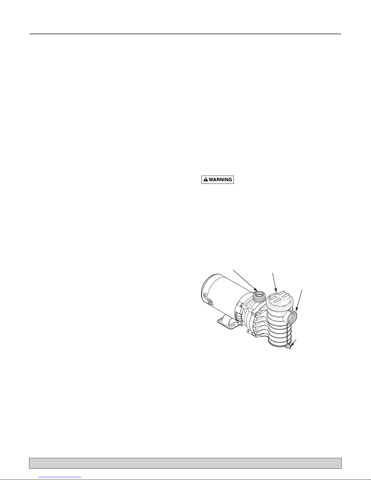
Figure 1
1
1
/2" NPT
Discharge
Port
Strainer
Basket
Cover
E
N
11/2" NPT
Suction Por
O
V
E
R
T
D
I
G
O
H
N
T
O
T
Drain
Plug
Electrical 5
For parts or assistance, call Flotec Customer Service at 1-800-365-6832
Hazardous voltage. Can shock, burn or
cause death. Plug pump into a grounded power supply.
Do not alter cord or plug. Disconnect power to motor
before working on electrical connections.
Ground Fault Circuit Interrupter (GFCI) tripping
indicates an electrical problem. If GFCI trips and
will not reset, have a qualified electrician inspect and
repair electrical system.
Exactly match supply voltage to nameplate voltage.
Incorrect voltage can cause fire or seriously damage motor and voids warranty. If in doubt consult a
licensed electrician.
Plug cord of pump directly into a GFCI protected
receptacle. Do not use an extension cord.
Voltage:
Voltage at motor must be not more than 10% above or
below motor nameplate rated voltage or motor may
overheat, causing overload tripping and reduced component life. If voltage is less than 90% or more than 110%
of rated voltage when motor is running at full load, consult power company.
Wiring:
Do not alter cord or plug on cord-connected units. Plug
in to a GFCI protected, grounded outlet only. If plug and
outlet do not match, consult a licensed electrician.
Table I, gives correct circuit breaker sizes for the pump
alone. If other lights or appliances are also on the same
circuit, be sure to add their amp loads to pump amp load
before figuring circuit breaker sizes. (If unsure how to do
this or if this is confusing, consult a licensed electrician.)
Use the load circuit breaker as the master on-off switch.
Install a Ground Fault Circuit Interrupter (GFCI) in circuit; it will sense a short-circuit to ground and disconnect power before it becomes dangerous to pool users.
For size of GFCI required and test procedures for GFCI,
see manufacturer’s instruction.
In case of power outage, check GFCI for tripping (which
will prevent normal pump operation). Reset if necessary.
Model Number Motor H.P. Branch Fuse Rating Amps* Max Load Amps Voltage/Hz/Phase
FP6121-01 3/4 15 9.0 115/60/1
FP6131 1 15 12.0 115/60/1
FPC6131 1 15 11.9 115/60/1
FPC6141 1-1/2 15 11.9 115/60/1
TABLE I - RECOMMENDED FUSING DATA
Values given in table below are for PUMP MOTOR ONLY. If additional accessories are installed on
pump motor circuit (heater, blower, etc.), include their amperage draw when figuring wire and circuit breaker sizes.
*Time delay fuses are recommended instead of standard fuses in any motor circuit.
Operation 6
For parts or assistance, call Flotec Customer Service at 1-800-365-6832
NEVER run pump dry! Running pump dry may
damage seals, causing leakage and flooding! Fill
pump with water before starting motor.
Before removing trap cover:
1. STOP PUMP before proceeding.
2. CLOSE GATE VALVES in suction and discharge pipes.
3. RELEASE ALL PRESSURE from pump and piping system.
Fire and burn hazard. Modern motors run
at high temperatures. To reduce the risk of fire, do not
allow leaves, debris, or foreign matter to collect around
the pump motor. To avoid burns when handling the
motor, let it cool for 20 minutes before trying to work on
it. An automatic internal cutoff switch protects the motor
from heat damage during operation.
NOTICE: Do not block pool return. To do so may flood
area causing damage to equipment and water damage to
surrounding area.
Priming Pump:
Open valves before starting system.
Release all pressure from filter, pump, and piping system;
see the filter owner’s manual.
In a flooded suction system (water source higher than
pump), pump will prime itself when suction and discharge valves are opened.
Pool Water:
Keep water level at least two inches above bottom of
skimmer opening when system is not in use. Failure to
do so can allow air to enter system, causing pump to
lose its prime.
Keep pool water “balanced”. Maintain the water pH
between 7.2 and 7.6.
Do not use or allow the use of the pool by anyone
using alcohol or drugs. The effects of hot water,
alcohol and/or drugs can cause dizziness and falling,
loss of consciousness, or heart attack.
Storage/Winterizing:
Explosion hazard. Purging the system with
compressed air can cause components to explode, with
risk of severe injury or death to anyone nearby. Use only
a low pressure (below 5 PSI), high volume blower when
air purging the pump, filter, or piping.
To prevent damage to components from fumes,
store chemicals away from pump. If possible, store
chemicals in another room.
NOTICE: Drain pump! Allowing pump to freeze will
damage pump and void warranty!
NOTICE: Do not use anti-freeze solutions (except propy-
lene glycol) in your pool system. Propylene glycol is
non-toxic and will not damage plastic system components; other anti-freezes are highly toxic and may damage plastic components in the system. Propylene glycol
is widely used as antifreeze in recreational vehicles.
Drain all water from pump and piping when expecting
freezing temperatures or when storing pump for a long
time (see instructions below).
Keep motor dry and covered during storage.
To avoid condensation/corrosion problems, do not cover
or wrap pump with plastic.
For outdoor/unprotected installations:
1. Pump down water level below all inlets to pool.
2. Enclose entire system in a weatherproof enclosure.
3. To avoid condensation/corrosion damage, allow ven-
tilation; do not wrap system in plastic.
4. Use a 40% propylene glycol/60% water solution to
protect pump to -50°F.
5. Follow pool manufacturer’s directions for storage of
pool.
Draining Pump:
Hazardous voltage. Can shock, burn or
cause death. Disconnect power before working on pump
or motor.
1. Close all valves on suction and return piping.
2. Remove drain plug in bottom of trap body.
3. Drain all piping and storage tanks exposed to freezing
temperatures.
4. Be sure no airlocks are holding water in the system.
5. To prevent pump from freezing, remove trap cover
and drain the tank body through the drain plug (Key
No. 12, Page 10). Clean pump thoroughly. Replace
trap cover.
6. Before restarting, replace all plugs and make sure all
pipe connections are tightly sealed.
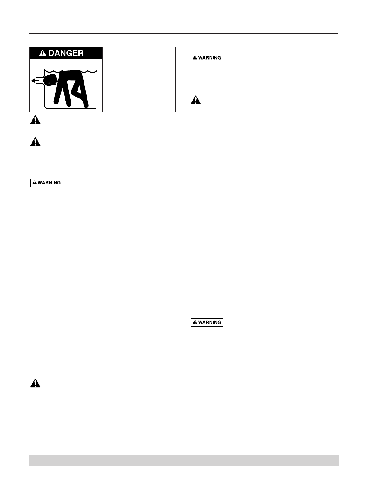
Hazardous Suction.
Can trap hair or body,
causing severe injury
or death.
• Do not block suction.
• Keep small children
under close adult
supervision at all times.
Operation / Pump Service 7
For parts or assistance, call Flotec Customer Service at 1-800-365-6832
Startup For Winterized Equipment:
1. Remove any temporary weather protection placed
around system for shutdown.
2. Follow filter manufacturer’s instructions for reactivation of the filter.
3. Inspect all electrical wiring for damage or deterioration over the shutdown period. Have a qualified serviceman repair wiring as needed.
4. Inspect and tighten all watertight connections.
5. Open all valves in suction and return piping.
6. Remove any winterizing plugs in piping system.
7. Drain all propylene glycol (RV antifreeze) from the
system.
8. Close all drain valves and replace all drain plugs in
piping system.
9. Prime pump according to instructions on Page 6.
10.Refill pool to proper water level.
PUMP SERVICE
To avoid dangerous or fatal electrical
shock hazard, disconnect power to motor before working on pump or motor.
Pump should only be serviced by qualified personnel.
Be sure to prime pump (Page 6) before restarting.
Before removing trap cover:
1. STOP PUMP before proceeding.
2. CLOSE GATE VALVES in suction and discharge pipes.
3. RELEASE ALL PRESSURE from pump and piping system.
No lubrication or regular maintenance is needed beyond
reasonable care and periodic cleaning.
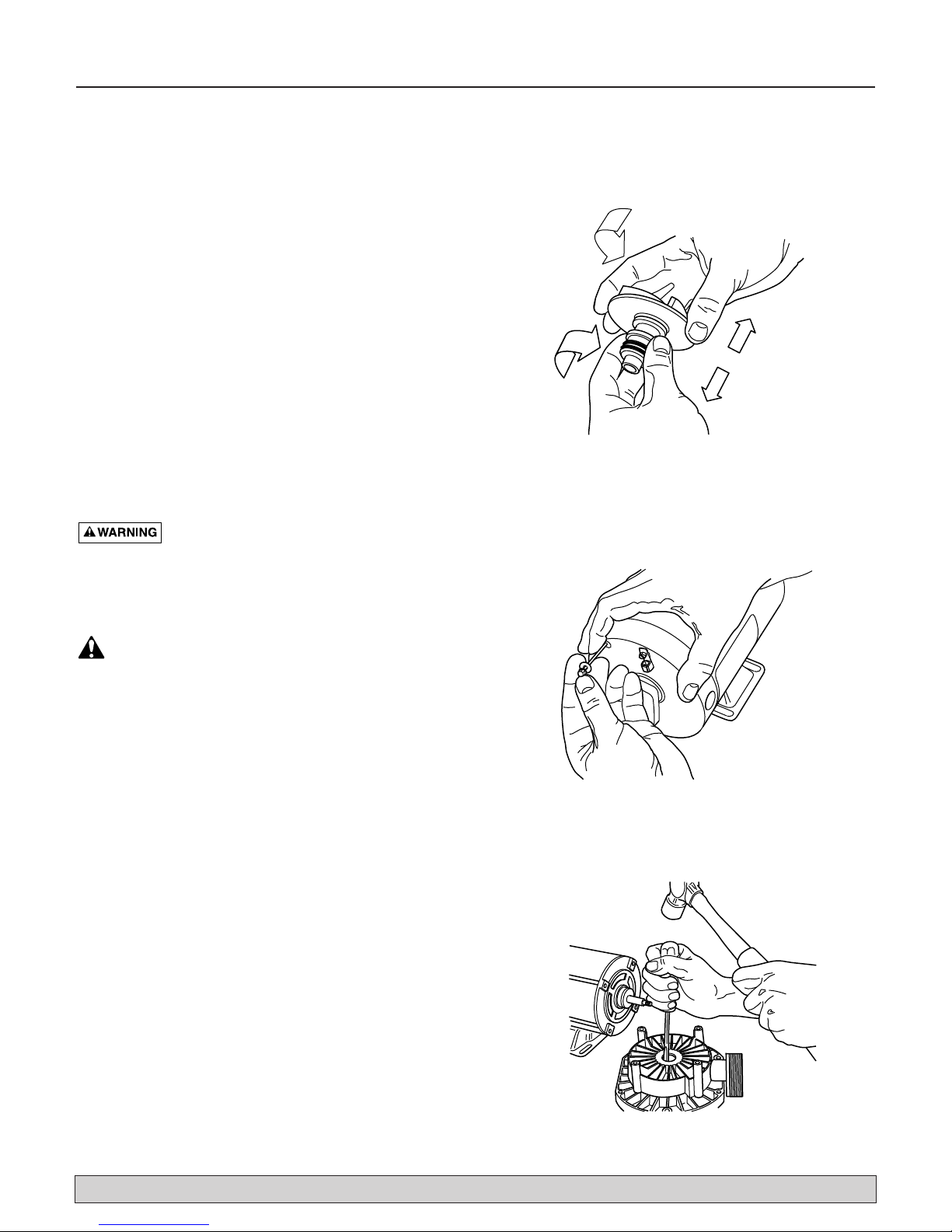
If shaft seal is worn or damaged, repair as follows:
Removing Old Seal:
1. Disconnect power to pump motor.
2. Drain pump; disconnect plumbing to allow access to
pump.
3. Remove four bolts holding trap body to seal plate;
remove trap body.
4. Remove shaft cover or motor canopy; using screw-
driver in slot on motor end of shaft or wrench on flats
of shaft extension, hold pump shaft and unscrew
impeller from shaft (turn counterclockwise). Rotating
half of seal will come off with impeller.
5. Carefully remove rotating part of seal from impeller
sleeve by pulling and turning on sealing washer and
spring (Figure 2). Do not damage impeller surface
where drive ring seats and seals.
6. Carefully remove four motor throughbolts from seal
plate (Figure 3); remove seal plate and use a screwdriver to tap ceramic seat out from the rear (Figure 4).
Do not damage seal cavity in seal plate.
7. Clean cavity from which seal was removed and clean
motor shaft.
Figure 2
Figure 3
Figure 4
Pump Service 8
For parts or assistance, call Flotec Customer Service at 1-800-365-6832
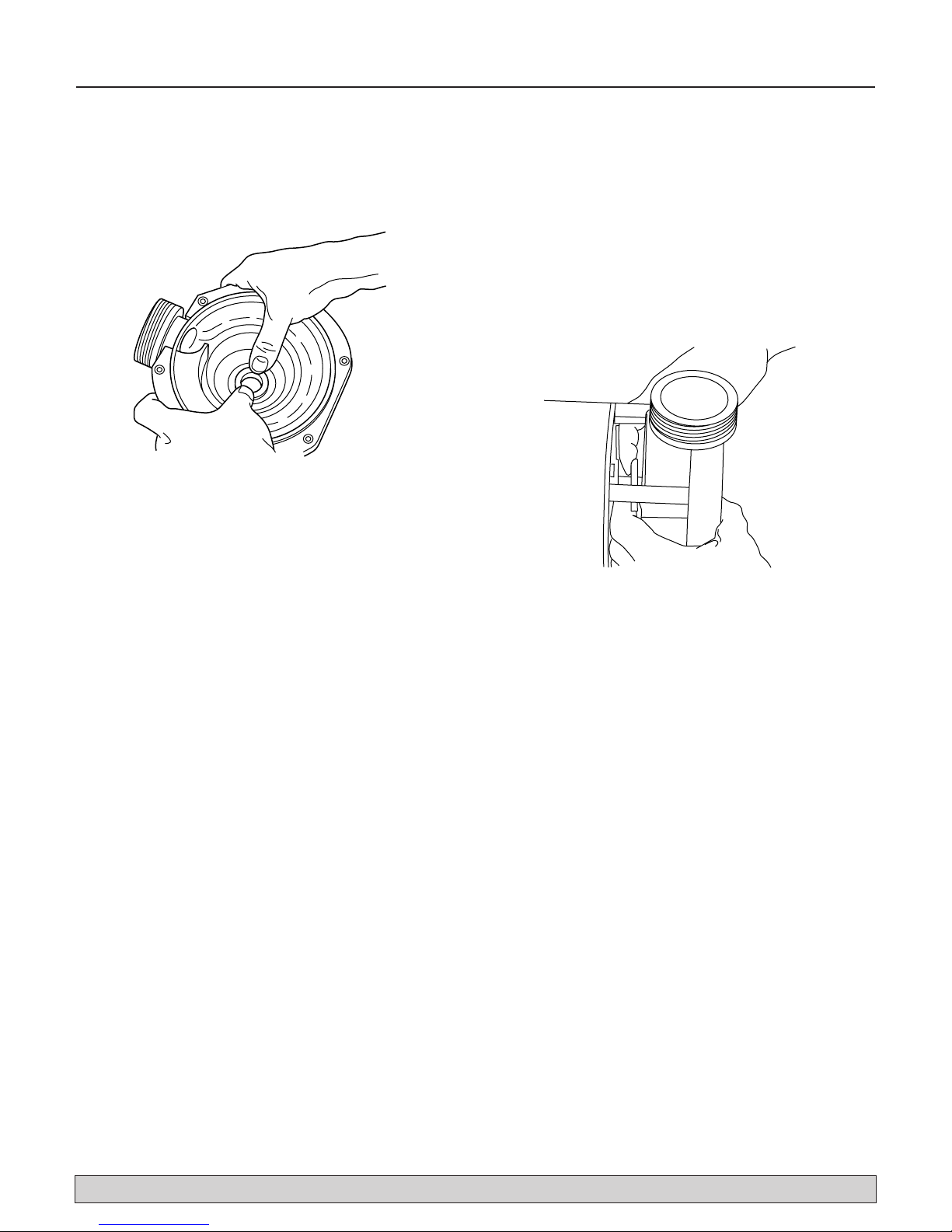
Installing New Seal:
1. Ceramic seat must be clean and free of dirt, grease,
dust, etc. Wet rubber cup gasket of ceramic seat with
small amount of water; press into cavity firmly and
squarely with finger pressure (Figure 5).
2. If ceramic seat will not locate properly, remove it,
place face up on bench, and reclean cavity. Ceramic
seat should now locate.
3. Seal must be free of dirt, grease, grit, scratches or
chips; be sure impeller sleeve is clean. Slide seal
assembly, rubber drive ring first, onto impeller sleeve
until drive ring bottoms on impeller back shroud.
4. Slip slinger over shaft; remount seal plate. Torque
throughbolts to 25 inch-lbs. (29 cm-kg).
5. Screw impeller onto shaft until it seats against shaft
shoulder. Work slinger over end of impeller sleeve so
it rides on sleeve (Figure 6).
6. Install wear ring on back of volute. NOTICE: Teeth on
wear ring interlock with ribs on trap body.
7. Remount trap body.
8. Reconnect unions; tighten hand tight only.
Figure 5
Figure 6

Troubleshooting 9
For parts or assistance, call Flotec Customer Service at 1-800-365-6832
Read and understand safety and operating instructions in this manual before doing any work on
pump.
Only qualified personnel should electrically test
pump motor.
FAILURE TO PUMP; REDUCED CAPACITY OR
DISCHARGE PRESSURE
Suction leaks/lost prime:
1. Pump must be primed; make sure that pump volute
and trap are full of water. See priming instructions,
Page 6.
2. Make sure there are no leaks in suction piping.
3. Make sure suction pipe inlet is well below the water
level to prevent pump from sucking air.
4. Suction lift of 1 to 2 feet (.3-.6M) will reduce performance. Suction lift of more than 2 feet (.6M) will prevent pumping and cause pump to lose prime. In
either case, move pump closer (vertically) to water
source. Make sure suction pipe is large enough.
Clogged pipe/trap/impeller, worn impeller:
1. Make sure suction trap is not clogged; if it is, clean
trap and strainer.
2. Make sure impeller is not clogged (follow instructions
under “Removing Old Seal”, Page 7; check impeller
for clogging; follow instructions under “Installing
New Seal”, Page 8, for reassembly).
3. Impeller and diffuser may be worn. If so, order
replacement parts from Repair Parts List, Page 10.
Inadequate Circulation:
1. Check trap basket; if plugged, turn pump off and
clean basket. Check and clean skimmer basket.
2. Check that gate valves are fully open.
3. Suction/discharge piping is too small.
4. Check and clean pool filter.
5. Check for clogged pipe/trap/impeller, Page 8.
6. Consult dealer/installer or service representative.
Circuit Breaker In Home Panel Trips Repeatedly:
1. Breaker must be of adequate capacity.
2. For GFCI breaker, test according to GFCI manufacturer’s instructions.
3. Be sure no other lights and appliances are on circuit.
4. Consult dealer/installer or service representative.
5. Voltage too high or too low. See “Voltage”, Page 5.
Electrical:
1. Pump may be running too slowly; check voltage at
motor terminals and at meter while pump is running.
If low, see wiring instructions or consult power company. Check for loose connections.
2. Pump may be too hot.
A. Check line voltage; if less than 90% or more than
110% of rated voltage consult a licensed electrician.
B. Increase ventilation.
C. Reduce ambient temperature.
D. Tighten any loose wiring connections.
3. Motor internal thermal overload protector is open.
Motor runs too hot. Turn power to motor off. Check
for proper voltage. Check for proper impeller or
impeller rubbing.
4. Consult dealer/installer or service representative.
Mechanical Troubles and Noise:
1. If suction and discharge piping are not adequately
supported, pump assembly will be strained. See
“Installation”, Page 4.
2. Do not mount pump on a wooden platform! Securely
mount on concrete platform for quietest performance.
3. Air leak in suction line (bubbles in water returning to
pool). Repair leak. Tighten trap lid.
4. Foreign matter (gravel, metal, etc.) in pump impeller.
Disassemble pump, clean impeller,
follow pump service instructions on Page 8 for
reassembly.
5. Cavitation.
Improve suction conditions.
Increase pipe size.
Decrease number of fittings.
Increase discharge pressure. Reduce flow by throttling
discharge gate valve.

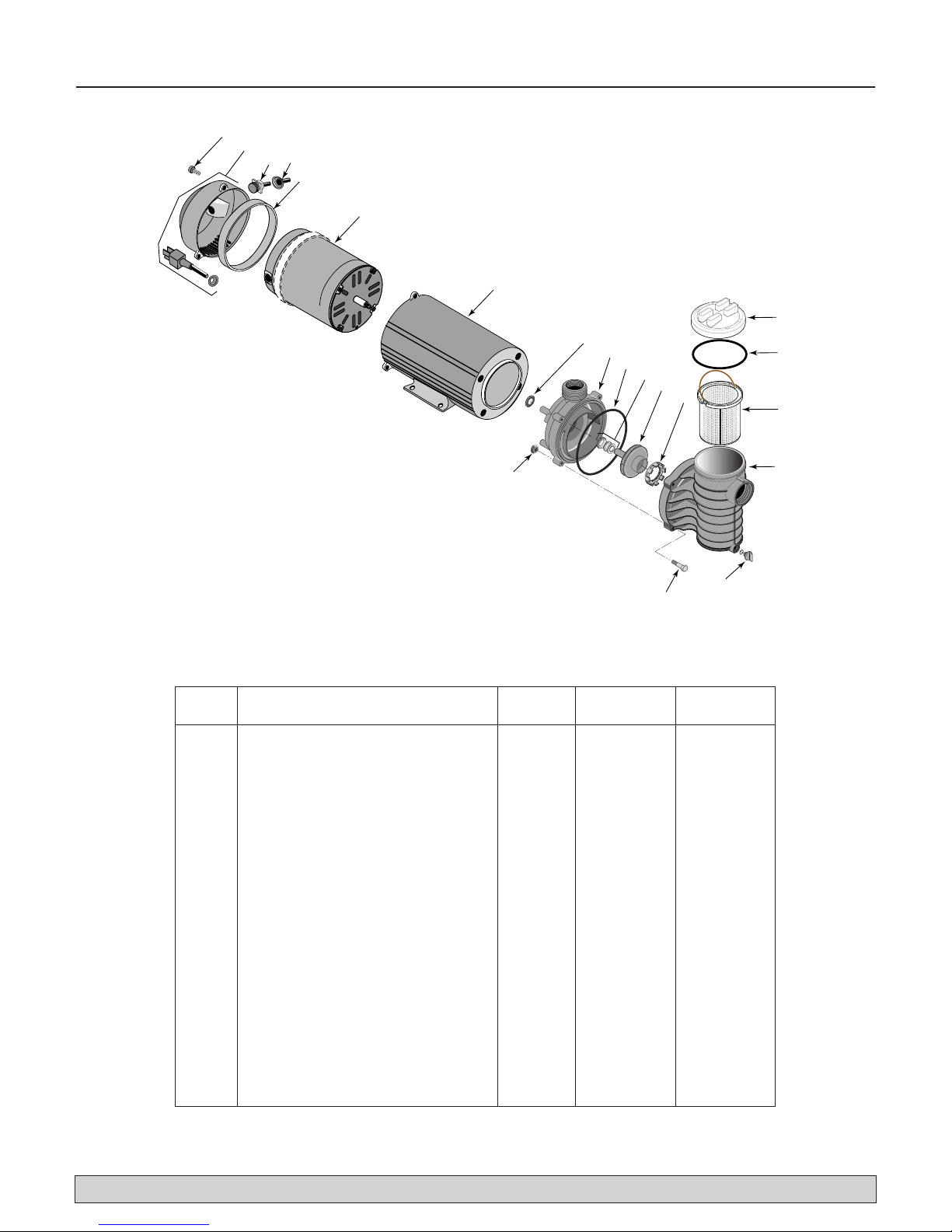
Repair Parts 10
For parts or assistance, call Flotec Customer Service at 1-800-365-6832
Key Part No. FP6121-01 FP6131
No. Description Used 3/4 HP 1 HP
1 Motor 1 AS920DLL AS920ELL
2 Slinger 1 17351-0009 17351-0009
3 Seal Plate 1 17500-0001 17500-0001
4 Seal Plate O-Ring 1 35505-1438 35505-1438
5 Shaft Seal 1 37400-0027S 37400-0027S
6 Impeller 1 17301-0113 17301-0112
7 Floating Wear Ring 1 17500-0004 17500-0004
8 Trap Body 1 17500-0002 17500-0002
9 Trap Lid 1 17500-0003 17500-0003
10 Trap Lid O-Ring 1 35505-1437 35505-1437
11 Trap Basket 1 17350-0100 17350-0100
12 Drain Plug 1 U178-920P U178-920P
13 Hex Head Bolt, 1/4-20x1-3/4" 4 30787-0005 30787-0005
14 Hex Nut 4 35402-0071 35402-0071
15 Cord 1 U117-1117 U117-1117
• Hardware Kit (2 Bolts, 2 Washers) 1 17290-0001 17290-0001
• Nameplate 1 U33-155 U33-155
• Warning Tag 1 61002-0013 61002-0013
• Caution Tag 1 C63-12 C63-12
• Decal - “GFCI Required” 1 U27-558 U27-558
Repair Parts List
• Not illustrated.
O
V
E
R
D
T
O
N
IG
O
H
T
T
E
N
9
1
2
15
3
4
5
10
11
6
7
8
14
3345 1198
13
12
Repair Parts 11
For parts or assistance, call Flotec Customer Service at 1-800-365-6832
Key Part No. FPC6131 FP6141
No. Description Used 1 HP 1-1/2 HP
1 End Cap Screw 3 37337-0085 37337-0085
2 End Cap and Cord Assembly 1 17190-0026 17190-0026
3 Toggle Switch 1 16920-0511 16920-0511
4 Toggle Switch Boot 1 32800-0107 32800-0107
5 Baffle Ring 1 17290-0004 17290-0004
6 Motor 1 AS901EL AS901SFL
7 Motor Cover 1 17190-0021 17190-0021
8 Slinger 1 17351-0009 17351-0009
9 Seal Plate 1 17500-0001 17500-0001
10 Seal Plate O-Ring 1 35505-1438 35505-1438
11 Shaft Seal 1 37400-0027 37400-0027
12 Impeller 1 17301-0112 17301-0112
13 Floating Wear Ring 1 17500-0004 17500-0004
14 Trap Lid 1 17500-0003 17500-0003
15 Trap Lid O-Ring 1 35505-1437 35505-1437
16 Trap Basket 1 17350-0100 17350-0100
17 Trap Body 1 17500-0002 17500-0002
18 Drain Plug with O-Ring 1 U178-920P U178-920P
19 Hex Head Bolt, 1/4-20x1-3/4" 4 30787-0005 30787-0005
20 Hex Nut 4 35402-0071 35402-0071
• Hardware Kit (2 Bolts, 2 Washers) 1 17290-0001 17290-0001
• Warning Tag 1 61002-0013 61002-0013
• Caution Tag 1 C63-12 C63-12
• Decal - “GFCI Required” 1 U27-558 U27-558
Repair Parts List
• Not illustrated.
For complete suction trap order Pkg. 115.
1
2
4
3
5
6
7
O
V
E
R
T
D
I
G
O
H
N
T
O
E
N
T
8
9
10
11
12
13
14
15
16
20
3345 1198 CAN
18
19
17
 Loading...