

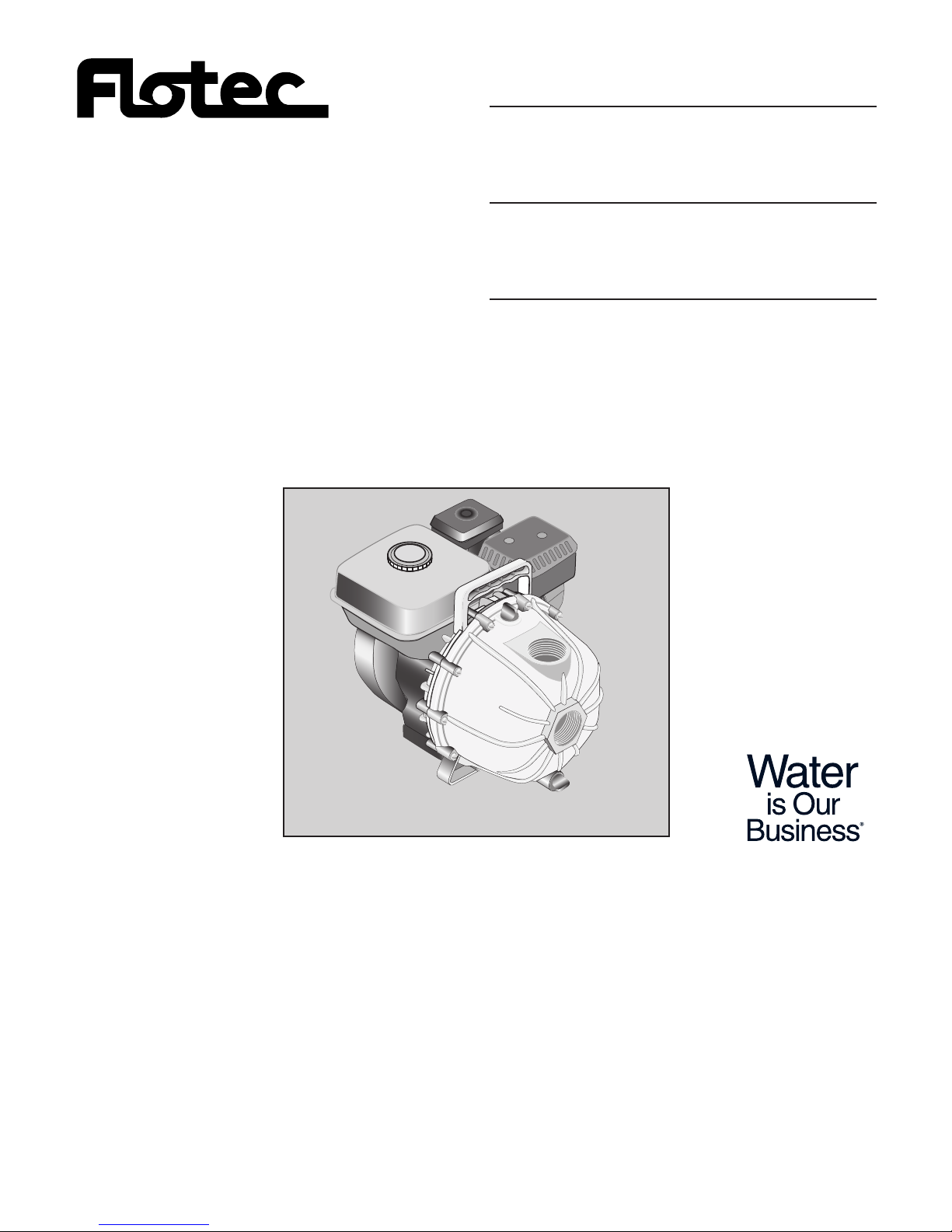
Flotec FP5455 Owner's Manual
OWNER’S MANUAL
Engine Drive Self-Priming Pump
NOTICE D’UTILISATION
Motopompe à amorçage
automatique
MANUAL DEL USUARIO
Bomba autocebante
accionada a motor
Installation/Operation/Parts
DO NOT return this pump to the store
where you purchased it.
For questions or problems about pump
operation, call 1-800-365-6832.
English . . . . . . . . . . . . . . . Pages 2-8
Installation/Fonctionnement/Pièces
NE PAS ramener cette pompe au
magasin ou elle a été achetée.
Pour toute question ou tout problème
concernant le fonctionnement de la
pompe, appeler le 1 800 365-6832.
Français . . . . . . . . . . . . Pages 9-15
Instalación/Operación/Piezas
No devuelva esta bomba a la tienda
donde la compró.
Para preguntas o problemas acerca de
la operación de la bomba llame al
1-800-365-6832.
Español . . . . . . . . . . .Paginas 16-22
FP753 (Rev. 2/11/05)
Model FP5455
®
P.O. Box 342, Delavan, WI 53115
Phone: 1-800-365-6832
Fax: 1-800-526-3757
E-Mail: info@flotecwater.com
Web Site: http://www.flotecwater.com
4584 0504
IMPORTANT
For best possible performance and continuous, satisfactory operation, read these instructions before installing your new pump. Should service be required, this
manual can be a valuable guide, it should be kept near the
installation for ready reference.
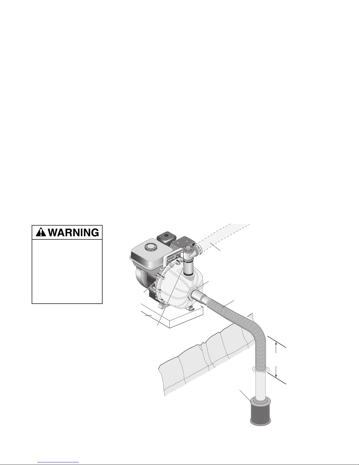
INSTALLATION
LOCATION
Place unit as close to water source as possible to minimize
suction lift, obtain the best pumping performance, and aid in
priming. A typical portable installation is shown in Figure 1.
For permanent installation, mount unit on a foundation that
will support the weight of pump and engine and also provide
stability while the pump is running. For most permanent
installations, it is advisable to bolt unit directly to foundation.
NOTICE: Settling and/or shifting during operation can cause
piping to place excessive strain on the pump and may damage pump case. Set pump on hard level surface.
SUCTION CONNECTION
Connect either rigid pipe or flexible suction hose to pump
suction as shown in Figure 1. If hose is selected, hose must
be rated to hold the suction pressure and prevent collapse
while the pump is running.
Make the suction line a continuous rise from the water
source to the pump. High spots can trap air and also make
priming difficult. Make sure all connections are tight and free
of air leaks.
NOTICE: Suction pipe or hose must be at least as large as the
pump suction inlet in order for the pump to operate properly.
Minimum depth for the suction inlet is determined by the
diameter of the suction line. See Figure 1.
NOTICE: Use a suction screen to keep debris out of pump.
DISCHARGE CONNECTIONS
Your pump is equipped with a single port discharge. Select
the appropriate size for the application. Install a “T” as
shown to allow priming the pump without disconnecting the
piping.
OPERATION
NOTICE: Do not start or run pump dry or damage to the
mechanical seal will result.
NOTICE: Add engine oil before startup. Refer to the
engine operation manual before startup.
PRIMING THE PUMP
A self priming pump only needs to be manually primed at the
first start-up. Once primed, under normal conditions the
pump will reprime automatically at each subsequent start-up.
If the pump is used in portable applications and the water has
been drained from the pump case, reprime before start-up
To prime, remove plug from top discharge outlet and fill
pump with water. Replace plug and start pump. The pump
will require a few minutes to evacuate air from the suction
line. After several minutes of operation, pump will be fully
primed and pumping water. Priming time will vary depending
on length and diameter of suction line.
2
Figure 1 – Typical Installation
Hazardous Suction.
Can trap persons
against suction inlet.
Always use strainer
on suction hose to
prevent entrapment.
Use pipe or reinforced hose to make
suction connection.
Hose must be strong enough to
not collapse during operation.
Suction screen area must be at least four
times suction pipe area.
All suction piping must slope up toward the
pump inlet.
Support the piping and fittings to reduce strain
on the pump case.
Priming Plug
Provide rigid
platform for pump.
Customer-supplied
Priming tee, plug
and nipple.
Discharge pipe not
smaller than the pump
discharge opening.
(2" x 25' Discharge hose
included in kit FP2731)
Pump Inlet
Suction hose
(2" x 15' Suction hose
included in kit FP2735).
Support pipe and
fittings.
Strainer or foot valve
(2" strainer included
in kit FP2735)
Depth of suction inlet at least
four (4) times the diameter of suction
pipe to avoid forming vortexes.
Example:
2" Pipe x 4 = 8" minimum depth.
25' Max

RUNNING THE ENGINE
Refer to engine operation part of this manual for starting and
operating instructions.
Pump performance varies depending on engine R.P.M.
Refer to engine operation to adjust engine speed.
MAINTENANCE
PUMP LUBRICATION
Pump liquid end does not require any grease or oil for lubrication. The mechanical seal is lubricated by water when the
pump is operating.
3
CAUSE CORRECTIVE ACTION
1. ENGINE
A. Speed too low Refer to engine section
B. Rotating and/or reciprocating parts drag Refer to engine section
C. Speed too high Maximum engine speed not to exceed engine manufacturer’s recommendation.
D. Loose or broken parts Refer to engine section
2. PUMP
E. Not primed Reprime, inspect suction system for air leaks, and or clack assembly.
F. Pump takes too long to prime Check for air leaks or defective check valve.
G. Flow through pump completely Locate and remove obstruction. Attach strainer.
or partially blocked
H. Internal leakage Check clearances between face of vanes and case. Should not exceed 1/32".
I. Rotating parts drag Inspect. Repair.
J. Loose or broken parts Inspect. Repair.
3. SYSTEM
K. Pressure required by system at design Compare pump pressure and flow rate against pump performance chart.
flow rate exceeds pressure rating of pump Reduce system pressure requirement. Increase pressure capability of pump.
L. Obstruction in suction piping Locate and remove obstruction. Attach strainer.
M. Suction lift too high Check with gauge or measure vertical distance between water surface and
center line of pump, allowing for friction loss in suction pipe. Reduce rate of
flow to obtain desired lift. Refer to pump performance chart.
N. Discharge head too low Decrease rate of flow
O. Suction inlet not immersed deep enough Refer to “Installation”
P. Leaky suction line or connection admitting air Repair or replace suction line. Tighten connections.
PROBABLE CAUSE
SYMPTOM ENGINE PUMP SYSTEM
ABCDEFGH I JKLMNOP
No water delivered X X X X X X X
Not enough water delivered X X X X X X X
Not enough pressure X X X X X X
Engine heats excessively X X X X X X X
Abnormal noise and/or vibration X X X X X X X
Pump works for a while, then stops XXXXXX
Depth Gallons per Minute at Discharge Pressure Maximum
to Water 15 PSI 25 PSI 35 PSI 45 PSI 50 PSI PSI
0 ft. 141 120 95 65 50 58
5 ft. 130 110 85 55 40 55
10 ft. 121 100 75 45 25 52
15 ft. 113 90 65 30 2 50
20 ft. 105 80 55 7 – 48
25 ft. 80 60 40 2 – 45
Troubleshooting Guide
Performance Chart

4
Pump Exploded View
• Not illustrated.
† Purchase locally.
* If needed, replace entire pump.
Item Description Qty. Part Number
1 Engine 1 *
2 Engine Mount Screws, 5/16-24 x .75 4 †
3 Seal Plate 1 M13906
4 O-Ring, Pump Body 1 M13910
5 Diffuser Gasket (O-Ring Segment) 1 M13918
6 Mechanical Seal 1 M13914
7Impeller 1 M13908
8 Impeller screw, 5/16-24 x 1.25 1 S23562
9 Rubber Washer for Impeller Screw 1 M13913
10 Diffuser 1 M13907
11 Flapper Valve 1 M13909
12 Plug 2 M13911
12A O-Ring, Plug 2 M13912
13 Pump Housing 1 M13905
14 Screw, 1/4-20x2.5 hex Head Machine Screw 10 †
15 Nuts, 1/4-20 10 †
16 Lockwasher 10 †
• Screw, Diffuser, #6 x 1/2 Self-Tapping 2 †
• Screw, Diffuser, #10 x 1-1/2 Self-Tapping 1 †
1
3
4
5
7
2
10
15
16
9
12
12A
13
6
8
11
12A
12
14
Engine Safety Precautions:
Fire and explosion hazard. Gasoline can
explode. Store gasoline away from the engine. Add gasoline
to the engine only when the engine is off.
Burn hazard. Hot surface.The engine gets
very hot during operation. Do not touch the engine surfaces.
Keep children away. Allow the engine to cool before moving
it indoors.
Deadly fumes. Carbon monoxide. Never run
the engine in an enclosed space. Only use outdoors with
plenty of ventilation.
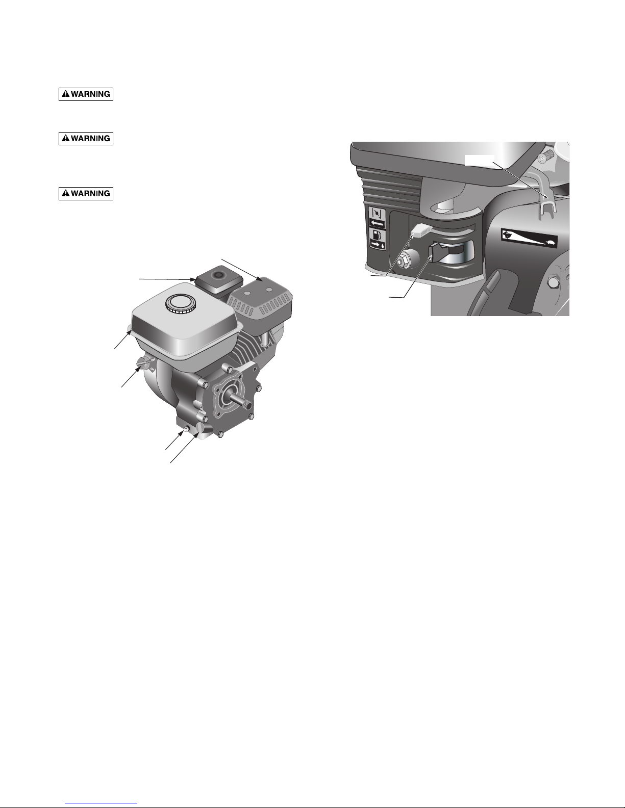
Engine Operation
Before starting the engine:
Check and Fill Oil
The engine is shipped without oil. It must be filled before
starting the engine.
Fill oil by removing the fill cap / dipstick. Add oil until the
level reaches the bottom of the opening. Check the oil level
by pushing the cleaned dipstick into the oil fill opening. DO
NOT SCREW IT IN. Remove the dipstick and inspect it. Add
oil if needed. Reinstall the cap / dipstick.
Oil capacity is 0.63 quarts (0.6 liter). 10W-30 oil should be
used in normal conditions. Use 10W-40 oil if the engine is to
be run in temperatures over 90°F (32°C) .
Note that the engine has a low-oil monitoring system. If the
oil level drops too low, the system will automatically turn off
the engine.
Add Gasoline
Fill gas tank with clean fresh gasoline. This should be
unleaded fuel that has an octane rating of 86 or higher.
Do not fill the tank to overflowing. Clean up any spilled gasoline before starting the engine.
Open Fuel Valve
Move the fuel valve to the right to allow fuel to the engine.
Close Choke
When starting a cold engine, move the choke control to the
left (closed). As the engine warms up move it towards the
right (open). A warm engine should start with the choke
open.
Position Throttle
Move the throttle (speed control) slightly to the left.
Turn Engine Switch On
The engine switch controls the ignition. turn it to the ON
position to start the engine. The same control is used to stop
the engine.
Pull Starter
Pull the handle on the recoil starter. Adjust throttle to desired
speed. Move the choke to the right as engine warms.
Stopping the Engine
Stop the engine by turning the engine switch to OFF.
Turn the fuel control to OFF (left).
5
PUMP ENGINE OPERATION AND MAINTENANCE
Muffler
Air Filter
Gas Tank
Engine On / Off Switch
Throttle
Engine Choke
Fuel Valve
Oil Drain Plug
Oil Fill and Dipstick
4646 0704

Engine Maintenance
Air filter
The air filter should be checked every month for dust and
dirt accumulation. Every 6 months the filter element should
be removed and cleaned. Clean the foam element with
detergent and warm water. Squeeze out excess water and
let it dry. Before reinstalling the filter element, soak it with
engine oil, and squeeze out the excess. Reinstall the filter.
The engine will smoke upon startup if too much oil is left in
the filter element.
Oil level
The oil level should be checked before each use.
Oil Change
The oil should be changed in the first month, and then every
6 months (or 100 hours of operation). To drain the oil, run
the engine until warm. Turn off the engine, remove the oil
drain plug, and let the the oil drain into a pan. Reinstall the
plug and fill with oil.
NOTE: Dispose of used oil responsibly. DO NOT pour it
down drains, onto the ground or put it in the trash. Most
communities have collection points for used oil.
Spark Plug
The spark plug should be checked and cleaned every 6
months or 100 hours.
The sparkplug should be replaced if it is damaged, or excessively worn.
The sparkplug is type BPR6ES (NGK) or equivalent. The
plug gap should be 0.030 in. (0.75 mm)
Engine Troubleshooting
If the engine won’t start:
• Check that there is gas in the tank
• Make sure the fuel valve is ON and that the engine switch
is ON
• Make sure there is enough oil in the engine to reset the
low-oil sensor
• Check that fuel is getting to the carburetor*
• Check for spark at the sparkplug*
* These checks to be done by persons with small-engine
experience.
Extended storage
If the pump will be stored for more than a month or two, follow the steps below.
• Drain Gasoline
• Change oil
• Squirt oil (or a chemical made for storing engines) in the
spark plug hole.
• Rotate engine slowly until resistance is felt (this indicates
that both valves are closed).
• Install spark plug
• Cover engine
6

7
1
Engine Replacement Parts
Item Description Qty. Part Number
1 Muffler Cover 1 2545-0011
2 Muffler 1 2545-0010
3 Spark Plug (use NGK brand #BPR6ES) 1 *
4 Air Filter Cover 1 2545-0018
5 Air Filter Cartridge 1 2545-0001
6 Starter Assembly 1 2545-0005
(includes rope,handle and recoil assembly)
7 Wing-nut for Air Filter 1 2545-0019
8 Muffler Cover Mounting Hardware 2 2545-0020
9 Oil Fill Cap 1 2545-0003
10 Oil Drain Plug and Washer 1 2545-0021
11 On / Off Switch and Cover 1 2545-0004
12 Fuel Tank 1 2545-0009
13 Fuel Tank Cap 1 2545-0002
* Purchase locally.
2
4 & 5
3
6
7
8
13
12
11
9
10

8
FLOTEC LIMITED WARRANTY
FLOTEC warrants to the original consumer purchaser (“Purchaser”) of its products that they are free from defects in material or
workmanship.
If within twelve (12) months from the date of the original consumer purchase any such product shall prove to be defective, it
shall be repaired or replaced at FLOTEC’s option, subject to the terms and conditions set forth below. Your original receipt of
purchase is required to determine warranty eligibility.
Exceptions to the Twelve (12) Month Warranty
Ninety (90) Day Warranty:
If within ninety (90) days from original consumer purchase any Drill Pump, Pitcher Pump, or In-Line Water Filter Cartridge
shall prove to be defective, it shall be replaced, subject to the terms set forth below.
Two (2) Year Warranty:
If within two (2) years from original consumer purchase any 1/3 HP Submersible Sump Pump shall prove to be defective, it
shall be repaired or replaced at FLOTEC’s option, subject to the terms and conditions set forth below.
Three (3) Year Warranty:
If within three (3) years from original consumer purchase any 4” Submersible Well Pump, or 1/2 HP Submersible Sump Pump,
shall prove to be defective, it shall be repaired or replaced at FLOTEC’s option, subject to the terms and conditions set forth
below.
Four (4) Year Warranty:
If within four (4) years from original consumer purchase any FLOODMATE 7000
TM
Submersible Sump Pump shall prove to be
defective, it shall be repaired or replaced at FLOTEC’s option, subject to the terms and conditions set forth below.
Five (5) Year Warranty:
If within five (5) years from original consumer purchase any Pre-Charge water system tank shall prove to be defective, it shall
be repaired or replaced at FLOTEC’s option, subject to the terms and conditions set forth below.
General Terms and Conditions
Purchaser must pay all labor and shipping charges necessary to replace product covered by this warranty. This warranty shall
not apply to acts of God, nor shall it apply to products which, in the sole judgement of FLOTEC, have been subject to negligence, abuse, accident, misapplication, tampering, alteration; nor due to improper installation, operation, maintenance or storage; nor to other than normal application, use or service, including but not limited to, operational failures caused by corrosion,
rust or other foreign materials in the system, or operation at pressures in excess of recommended maximums.
Requests for service under this warranty shall be made by returning the defective product to the Retail outlet or to FLOTEC as
soon as possible after the discovery of any alleged defect. FLOTEC will subsequently take corrective action as promptly as reasonably possible. No requests for service under this warranty will be accepted if received more than 30 days after the term of
the warranty.
This warranty sets forth FLOTEC’s sole obligation and purchaser’s exclusive remedy for defective products.
FLOTEC SHALL NOT BE LIABLE FOR ANY CONSEQUENTIAL, INCIDENTAL, OR CONTINGENT DAMAGES WHATSOEVER.
THE FOREGOING WARRANTIES ARE EXCLUSIVE AND IN LIEU OF ALL OTHER EXPRESS WARRANTIES. IMPLIED WAR-
RANTIES, INCLUDING BUT NOT LIMITED TO THE IMPLIED WARRANTIES OF MERCHANTABILITY AND FITNESS FOR A
PARTICULAR PURPOSE, SHALL NOT EXTEND BEYOND THE DURATION OF THE APPLICABLE EXPRESS WARRANTIES
PROVIDED HEREIN.
Some states do not allow the exclusion or limitation of incidental or consequential damages or limitations on how long an
implied warranty lasts, so the above limitations or exclusions may not apply to you. This warranty gives you specific legal
rights and you may also have other rights which vary from state to state.
FLOTEC • P.O. Box 342 • Delavan, WI U.S.A. 53115
Phone: 1-800-365-6832 • Fax: 1-800-526-3757
E-Mail: info@flotecwater.com • Web Site: http://www.flotecwater.com
ENGINE
Refer to engine manufacturer’s operating manual for complete maintenance and warranty.
 Loading...