

Flotec FP5100 Series Owner's Manual
OWNER’S MANUAL
Corrosion Resistant Centrifugal
Lawn Sprinkler Pump
NOTICE D’UTILISATION
Pompe centrifuge et inoxydable
pour l’arrosage du gazon
MANUAL DEL USUARIO
Bomba centrifuga resistente
a la corrosion para rociadores
de césped
Installation/Operation/Parts
For further operating, installation,
or maintenance assistance:
Call 1-800-365-6832
English . . . . . . . . . . . . . . Pages 2-11
Installation/Fonctionnement/Pièces
Pour plus de renseignements
concernant l’utilisation,
l’installation ou l’entretien,
Composer le
1 (800) 365-6832
Français . . . . . . . . . . . Pages 12-21
Instalación/Operación/Piezas
Para mayor información sobre el
funcionamiento, instalación o
mantenimiento de la bomba:
Llame al 1-800-365-6832
Español . . . . . . . . . . .Paginas 22-31
©2005 S190 (Rev. 12/7/05)
Series FP5100
P.O. Box 342, Delavan, WI 53115
Phone:
1-800-365-6832
Fax:
1-800-526-3757
E-Mail:
info@flotecwater.com
Web Site:
http://www.flotecwater.com
®
®
1538 0195
Safety 2
For parts or assistance, call Flotec Customer Service at 1-800-365-6832
READ AND FOLLOW
SAFETY INSTRUCTIONS!
This is the safety alert symbol. When you see this
symbol on your pump or in this manual, look for
one of the following signal words and be alert to the
potential for personal injury:
warns about hazards that will cause serious
personal injury, death or major property damage if
ignored.
warns about hazards that can cause serious
personal injury, death or major property damage if
ignored.
warns about hazards that will or can cause
minor personal injury or property damage if ignored.
The label NOTICE indicates special instructions which
are important but not related to hazards.
Carefully read and follow all safety instructions in this
manual and on pump.
Keep safety labels in good condition.
Replace missing or damaged safety labels.
Make workshops childproof; use padlocks and master
switches; remove starter keys.
ELECTRICAL SAFETY
Capacitor voltage may be hazardous. To
discharge motor capacitor, hold insulated handle screwdriver BY THE HANDLE and short capacitor terminals
together. Do not touch metal screwdriver blade or
capacitor terminals. If in doubt, consult a qualified
electrician.
GENERAL SAFETY
Do not touch an operating motor. Modern
motors are designed to operate at high temperatures. To
avoid burns when servicing pump, allow it to cool for 20
minutes after shut-down before handling.
Pump is designed as a lawn sprinkler only. To avoid heat
built-up, over pressure hazard and possible injury, do not
use in a domestic water system. Do not use as a booster
pump; pressurized suction may cause pump body to
explode.
Do not allow pump or any system component to freeze.
To do so will void warranty.
Pump water only with this pump.
Periodically inspect pump and system components.
Wear safety glasses at all times when working on pumps.
Keep work area clean, uncluttered and properly lighted;
store properly all unused tools and equipment.
Keep visitors at a safe distance from the work areas.
“Dead Heading” a pump means running the pump
while little or no water is released from the system.
Never run pump above recommended pressure shown
on the performance chart.
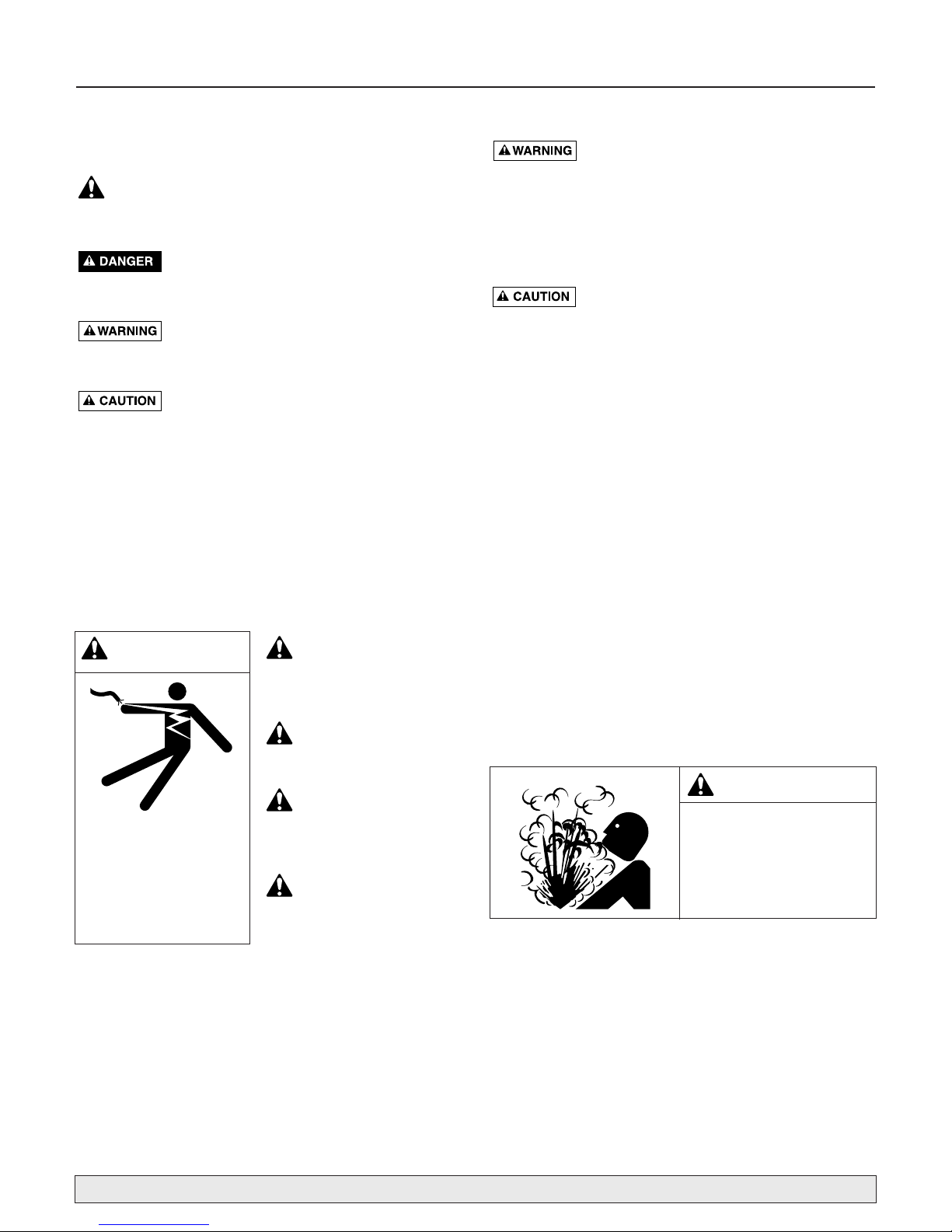
WARNING
Hazardous pressure!
Do not run pump against
closed discharge.
Release all pressure on
system before working on
any component.
WARNING
Hazardous voltage.
Can shock, burn, or
cause death.
Ground pump before
connecting to power
supply. Disconnect power
before working on pump,
motor or tank.
Wire motor for correct
voltage. See “Electrical”
section of this manual and
motor nameplate.
Ground motor before
connecting to power
supply.
Meet National Electri-
cal Code, Canadian
Electrical Code, and local
codes for all wiring.
Follow wiring instruc-
tions in this manual
when connecting motor to
power lines.

Table of Contents 3
Thank you for purchasing a top quality, factory tested pump.
Page
General Safety .....................................................................................................2
Installation ........................................................................................................4,5
Electrical...........................................................................................................6,7
Operation ............................................................................................................8
Troubleshooting ...................................................................................................9
Repair Parts .......................................................................................................10
Warranty............................................................................................................11
For parts or assistance, call Flotec Customer Service at 1-800-365-6832
Installation 4
BEFORE YOU INSTALL YOUR PUMP
NOTICE: Well must not be more than 20' (6.1m) depth
to water.
Step 1. Long runs and many fittings increase friction and
reduce flow. Locate pump as close to well as
possible; use as few elbows and fittings as possible. Be sure suction line is straight and angles
toward pump.
Step 2. Be sure well and pipe are clear of sand, dirt and
scale. Foreign matter will plug pump and void
warranty. Use new pipe for best results.
Step 3. Protect pump and all piping from freezing.
Freezing will split pipe, damage pump and void
warranty. Check locally for frost protection
requirements (usually pipe must be 12" (30.5cm)
below frost line and pump must be insulated).
Step 4. Be sure all pipes and foot valve are clean and in
good shape.
Step 5. No air pockets in suction pipe.
Step 6. No leaks in suction pipe. Use Teflon tape or
Plasto-Joint Stik to seal pipe joints.
Step 7. Unions installed near pump and well will aid in
servicing. Leave room to use wrenches.
Pump body may explode if used as booster
pump. DO NOT use in booster application.
Motor normally operates at high temperature and will be too hot to touch. It is protected from
heat damage during operation by an automatic internal
cutoff switch. Before handling pump or motor, stop
motor and allow it to cool for 20 minutes.
WELL PIPE INSTALLATION
NOTICE: Use installation method below which matches
your well type.
CASED WELL/DUG WELL INSTALLATION
Step 1. Inspect foot valve to be sure it works freely.
Inspect strainer to be sure it is clean and secure.
Step 2. Connect foot valve and strainer to first length of
suction pipe and lower pipe into well. Add sections of pipe as needed, using Teflon tape on
male threads (use 1-1/2" pipe for suction pipe).
Be sure all suction pipe is leakproof or pump will
lose prime and fail to pump. Install foot valve 10
to 20 ft. (3 to 6 m) below lowest level to which
water will drop while pump is operating (pumping water level). Your well driller can furnish this
information.
Step 3. To prevent sand and sediment from entering
pumping system, foot valve/strainer should be at
least 5 ft. (1.5 m) above bottom of well.
Step 4. When proper depth is reached, install sanitary
well seal over pipe and in well casing. Tighten
bolts to seal casing.
Step 5. When using foot valve, a priming tee and plug
are recommended. (Fig. 1).
For parts or assistance, call Flotec Customer Service at 1-800-365-6832
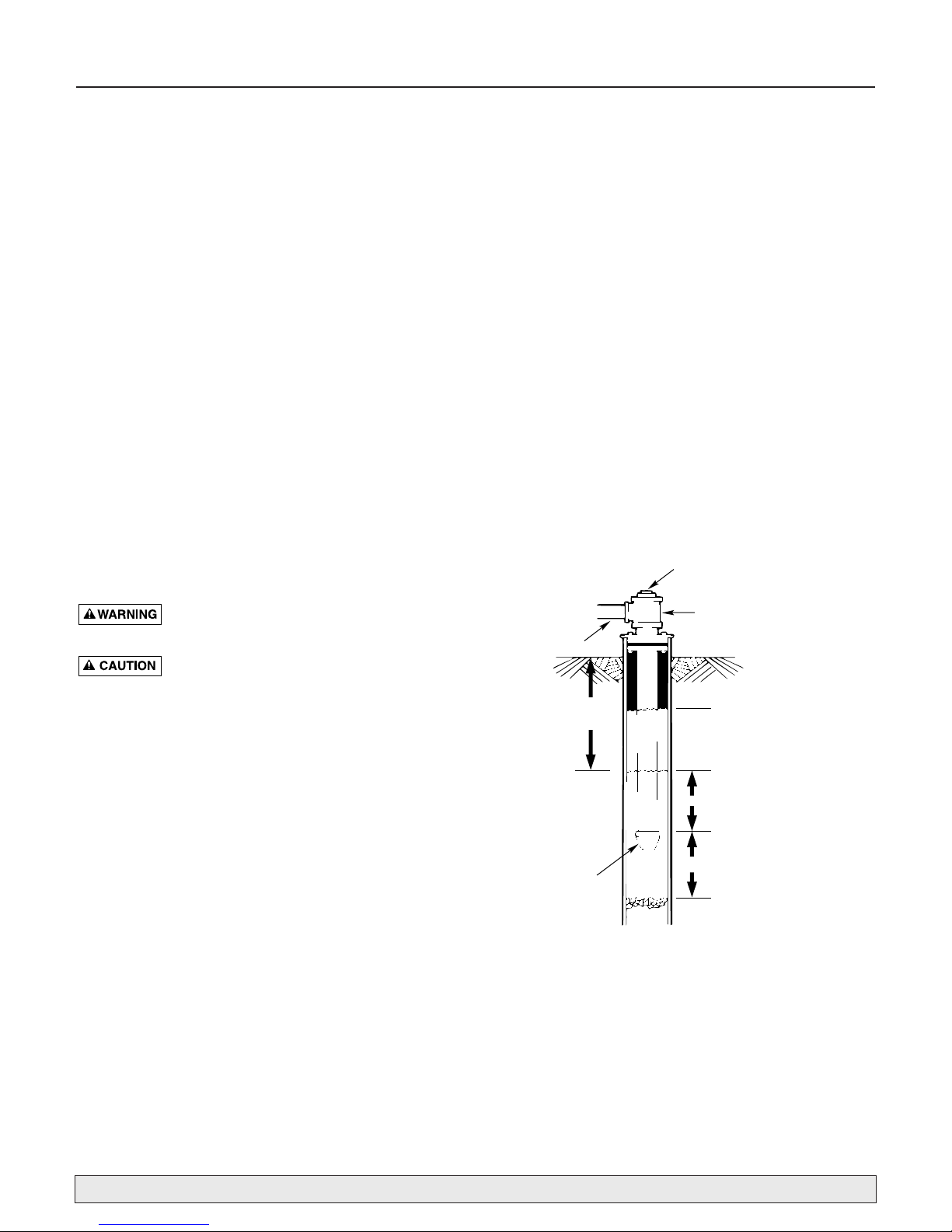
Figure 1: Cased/Dug Well Installation
Priming plug
Priming tee
Suction
pipe
20' (6 m) max.
Standing water
level (pump off)
Drawdown water
level (pump on)
10-20' (3-6 m)
Foot
Valve
At least 5 feet (1.5 m)
828 0993
Installation 5
DRIVEN POINT INSTALLATION
Step 1. Connect suction pipe to drive point (Fig. 2). Keep
horizontal pipe run as short as possible. Use
Teflon tape on male pipe threads. Multiple well
points may be necessary to provide sufficient
water to pump.
Step 2. Install check valve in horizontal pipe. Flow
arrow on check valve must point toward pump.
HORIZONTAL PIPING FROM WELL TO PUMP
Step 1. Pump performance will be decreased if less that
1-1/2" pipe is used as suction pipe.
Step 2. To aid priming on well point installations, install
line check valve. Be sure check valve flow arrow
points toward pump.
DISCHARGE PIPE SIZES
Discharge pipe size should be increased to reduce pressure losses caused by friction on long pipe runs.
• Up to 100' (30.5 m) run: Same size as pump discharge port.
• 100' - 300' (30.5 - 91.4 m) run: Increase one pipe
size.
• 300' - 600' (91.4 - 182.9 m) run: Increase two pipe
sizes.
LAWN SPRINKLING APPLICATION
This pump is designed for lawn sprinkling. Delivers plenty of water at full sprinkler pressure. Pumps from pond,
cistern or well points.
Pump discharge can be divided to supply 4 or more
sprinkler systems.
Do not use in booster pump applications.
PUMP/PIPING INSTALLATION
If turning pump on and off by pressure, a pressure switch
and tank are required. For proper installation and operation instructions call Customer Service.
Use rigid pipe. Do not use hose or plastic tubing. See
“Well Pipe Installation” for more information.
NOTICE: Use only Teflon tape or Teflon based joint
compounds for making all threaded connections to the
pump itself. Do not use pipe joint compounds on plastic
pumps: they can react with the plastic in pump components. Make sure that all pipe joints in the suction pipe
are air tight as well as water tight.
If the suction pipe can
suck air, the pump will not be able to pull water from
the well.
Step 1. Bolt pump to solid, level foundation.
Step 2. Support all piping connected to pump.
Step 3. Wrap 1-1/2 to 2 layers of Teflon tape clockwise
(as you face end of pipe) on all male threads
being attached to pump.
Step 4. Tighten joints hand tight plus 1-1/2 turns. Do not
overtighten.
Step 5. Replace prime plug with pressure gauge. This
will aid in sizing zones, troubleshooting, and following pump performance chart.
NOTICE: Install pump as close to well head as possible.
Long piping runs and many fittings create friction and
reduce flow.
NOTICE: For long horizontal pipe runs, install a priming
tee between check valve and well head (Fig. 1). For driven point installations, install check valve. Be sure that
check valve flow arrow points toward pump.
For parts or assistance, call Flotec Customer Service at 1-800-365-6832
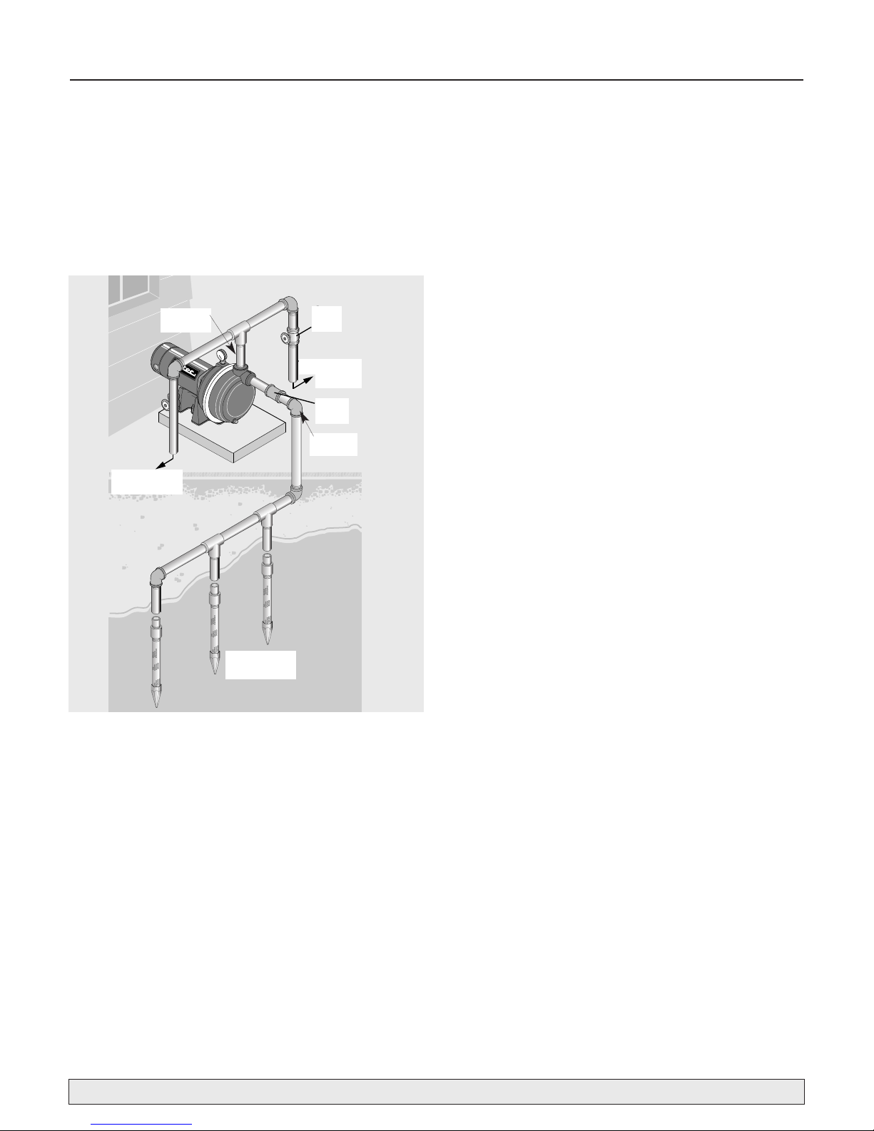
Figure 2: Driven Point Installation, Multiple Well Points
Suction
Pipe
To sprinker
heads
Multiple well
points
Gate
valve
Discharge
Pipe
Check
Valve
To sprinker
heads
To sprinkler
heads
Multiple well
points
Gate
valve
To sprinkler
heads
Check
valve
Electrical 6
For parts or assistance, call Flotec Customer Service at 1-800-365-6832
MOTOR SWITCH SETTINGS
Dual-voltage motors (motors that can operate at either
115 or 230 volts), are set at the factory to 230 volts. Do
not change motor voltage setting if line voltage is 230
volts, or if you have a single voltage motor.
NOTE: Never wire a 115 volt motor to a 230 volt line.
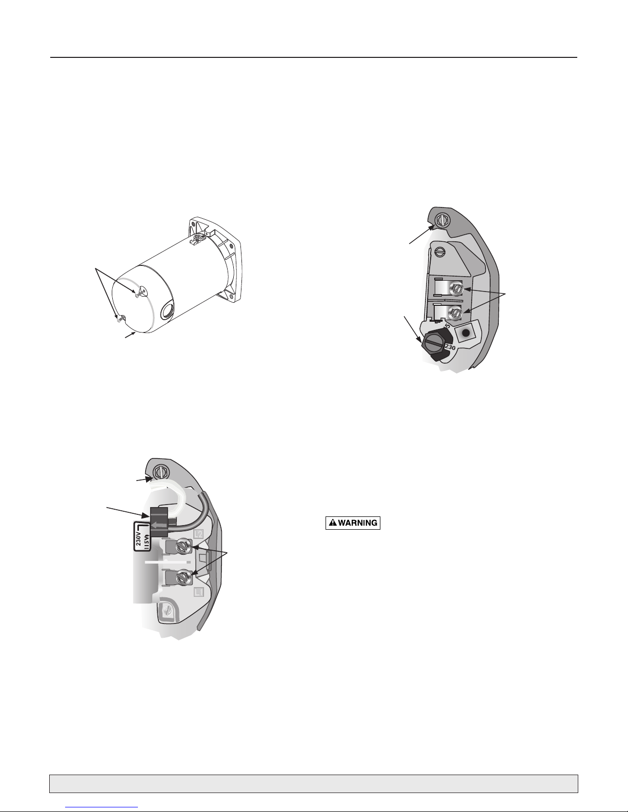
REMOVE MOTOR END COVER
If you have a dual-voltage motor, and will connect it to
115 volts, follow the procedure below.
You will need to remove the motor end cover to change
the voltage setting.
Your motor terminal board (located under the motor end
cover) should look like one of those below.
PLUG TYPE VOLTAGE SELECTOR
To change to 115 volts:
1. Make sure power is off.
2. Pull the plug straight up.
3. Move and attach the plug at the 115 volt position. The
plug will now cover 2 metal tabs. The arrow on the
plug will point to 115V.
4. Attach the power lead wires to the power lead termi-
nals. Make sure the wires are secure.
5. Attach the ground wire to the green ground screw
6. Reinstall the Motor end cover
Go to Wiring Connections below.
DIAL TYPE VOLTAGE SELECTOR
To change to 115 volts:
1. Make sure power is off.
2. Turn the dial counter-clockwise until 115 shows in the
dial window.
3. Attach the power lead wires to the power lead termi-
nals. Make sure the wires are secure.
4. Attach the ground wire to the green ground screw
5. Reinstall the Motor end cover
Go to Wiring Connections below.
Hazardous voltage. Can shock, burn, or
cause death. Disconnect power to motor before working
on pump or motor. Ground motor before connecting to
power supply.
Figure 3: Removing Motor End Cover
Figure 4: Voltage set to 230 volts, Plug Type
Figure 5:Voltage set to 230 volts, Dial Type
End Cover Screws
Motor
End Cover
Ground
Screw
Voltage Change
Plug
Ground
Screw
Power Lead
Voltage
Change Dial
Terminals
Power Lead
Terminals
Electrical 7
WIRING
Ground motor before connecting to electrical
power
supply. Failure to ground motor can cause severe or
fatal electrical shock hazard.
Do not ground to a gas supply line.
To avoid dangerous or fatal electrical shock, turn
OFF power to motor before working on electrical
connections.
Supply voltage must be within ±10% of nameplate
voltage. Incorrect voltage can cause fire or damage motor and voids warranty. If in doubt consult a
licensed electrician.
Use wire size specified in Wiring Chart (below). If
possible, connect pump to a separate branch circuit with no other appliances on it.
Wire motor according to diagram on motor name-
plate. If nameplate diagram differs from diagrams
above, follow nameplate diagram.
Step 1. Install, ground, wire and maintain this pump in
accordance with electrical code requirements.
Consult your local building inspector for information about codes.
Step 2. Provide a correctly fused disconnect switch for
protection while working on motor. Consult
local or national electrical codes for switch
requirements.
Step 3. Disconnect power before servicing motor or
pump. If the disconnect switch is out of sight of
pump, lock it open and tag it to prevent unexpected power application.
Step 4. Ground the pump permanently using a wire of
the same size as that specified in wiring chart,
below. Make ground connection to green
grounding terminal under motor canopy marked
GRD. or .
Step 5. Connect ground wire to a grounded lead in the
service panel or to a metal underground water
pipe or well casing at least 10 feet long. Do not
connect to plastic pipe or insulated fittings.
Step 6. Protect current carrying and grounding conduc-
tors from cuts, grease, heat, oil, and chemicals.
Step 7. Connect current carrying conductors to terminals
L1 and L2 under motor canopy. When replacing
motor, check wiring diagram on motor nameplate against Figure 3. If the motor wiring diagram does not match either diagram in Figure 3,
follow the diagram on the motor.
IMPORTANT: 115/230 Volt single phase models are
shipped from factory with motor wired for 230 volts. If
power supply is 115 volts, remove motor canopy and
reconnect motor as shown in Figure 3. Do not try to run
motor as received on 115 volt current.
Step 8. Motor has automatic internal thermal overload
protection. If motor has stopped for unknown
reasons, thermal overload may restart it unexpectedly, which could cause injury or property
damage. Disconnect power before servicing
motor.
Step 9. If this procedure or the wiring diagrams are con-
fusing, consult a licensed electrician.
For parts or assistance, call Flotec Customer Service at 1-800-365-6832
Branch AWG
DISTANCE IN FEET(METERS) FROM MOTOR TO SUPPLY
Max. Fuse Min.
0 - 100 101 - 200 201 - 300 301 - 400 401 - 500
Pump Load Rating* Wire
(0 - 30) (31 - 61) (62 - 91) (92 - 122) (123 - 152)
Model HP Volts Amp Amp Size (mm2) AWG WIRE SIZE (mm2)
FP5162 1 115/230 14.8/7.4 20/15 12/14 (3/2) 12/14 (3/2) 8/14 (8.4/2) 6/14 (14/2) 6/12 (14/3) 4/10 (21/5.5)
FP5172 1-1/2 115/230 19.2/9.6 25/15 10/14 (5.5/2) 10/14 (5.5/2) 8/14 (8.4/2) 6/12 (14/3) 4/10 (21/5.5) 4/10 (21/5.5)
FP5182 2 115/230 24/12 30/15 10/14 (5.5/2) 10/14 (5.5/2) 6/14 (14/2) 6/12 (14/3) 4/10 (21/5.5) 4/10 (21/5.5)
Wiring Chart – Recommended Wire and Fuse Sizes for 115 and 230 volts
* Duel element or Fusetron time delay fuses recommended for all motor circuits.
Operation 8
PRIMING THE PUMP
NOTICE: 'Priming' refers to pump expelling all air in the
system and beginning to move water from its source out
into system. It does not refer only to pouring water into
pump (although pouring water in is usually the first step).
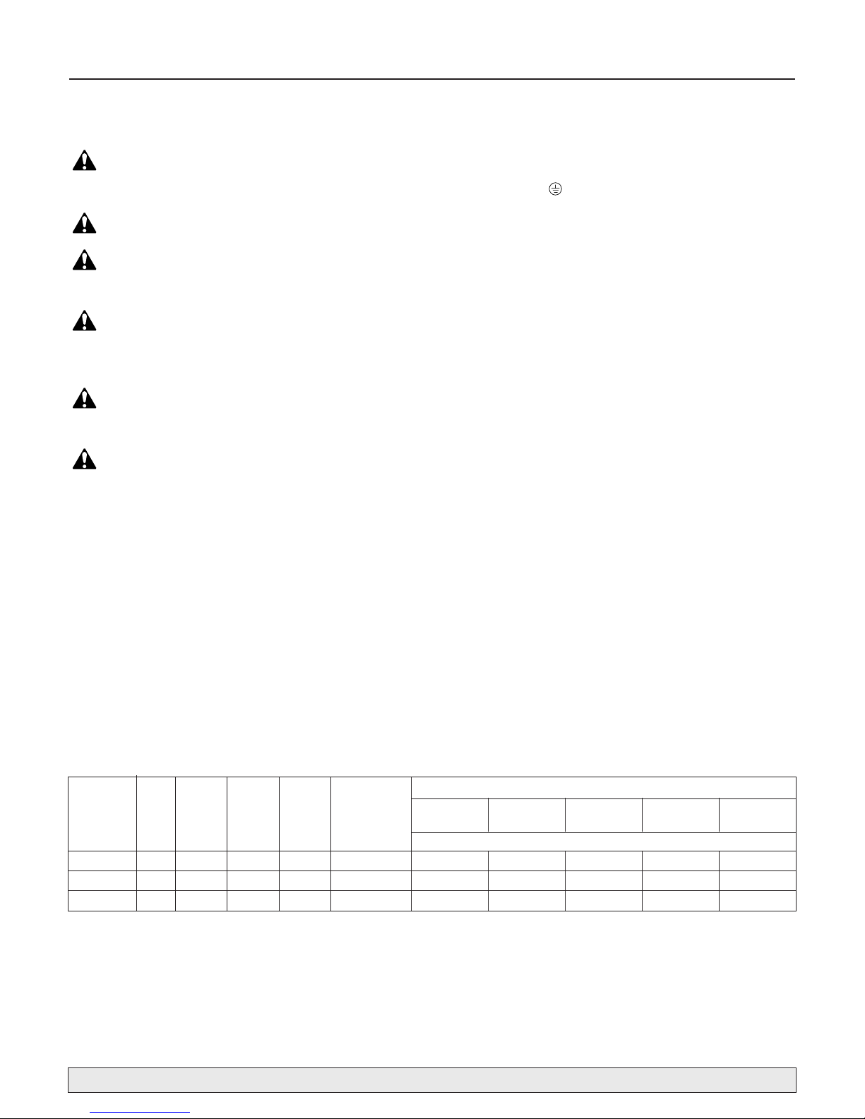
NEVER run pump dry. Running pump without water may cause pump to overheat, damaging seal
and possibly causing burns to
persons handling pump. Fill pump with water before
starting.
Step 1. Remove priming plug.
Step 2. Make sure suction and discharge valves and any
hoses on discharge side of pump are open.
Step 3. Fill pump and suction pipe with water (Fig. 6).
Step 4. Replace priming plug, using Teflon tape on
thread; tighten plug.
NOTICE: If priming tee and plug have been pro-
vided for long horizontal run, be sure to fill suction pipe through this tee and replace plug. (Use
Teflon tape on plug.)
Step 5. Start pump; water should be produced in 10
minutes or less, time depends on depth to water
(not more than 20' (6 m)) and length of horizontal run (10' (3 m) of horizontal suction pipe = 1'
(30.5 cm) of vertical lift due to friction losses in
pipe). If no water is produced within 10 minutes,
stop pump, release all pressure, remove priming
plug, refill and try again.
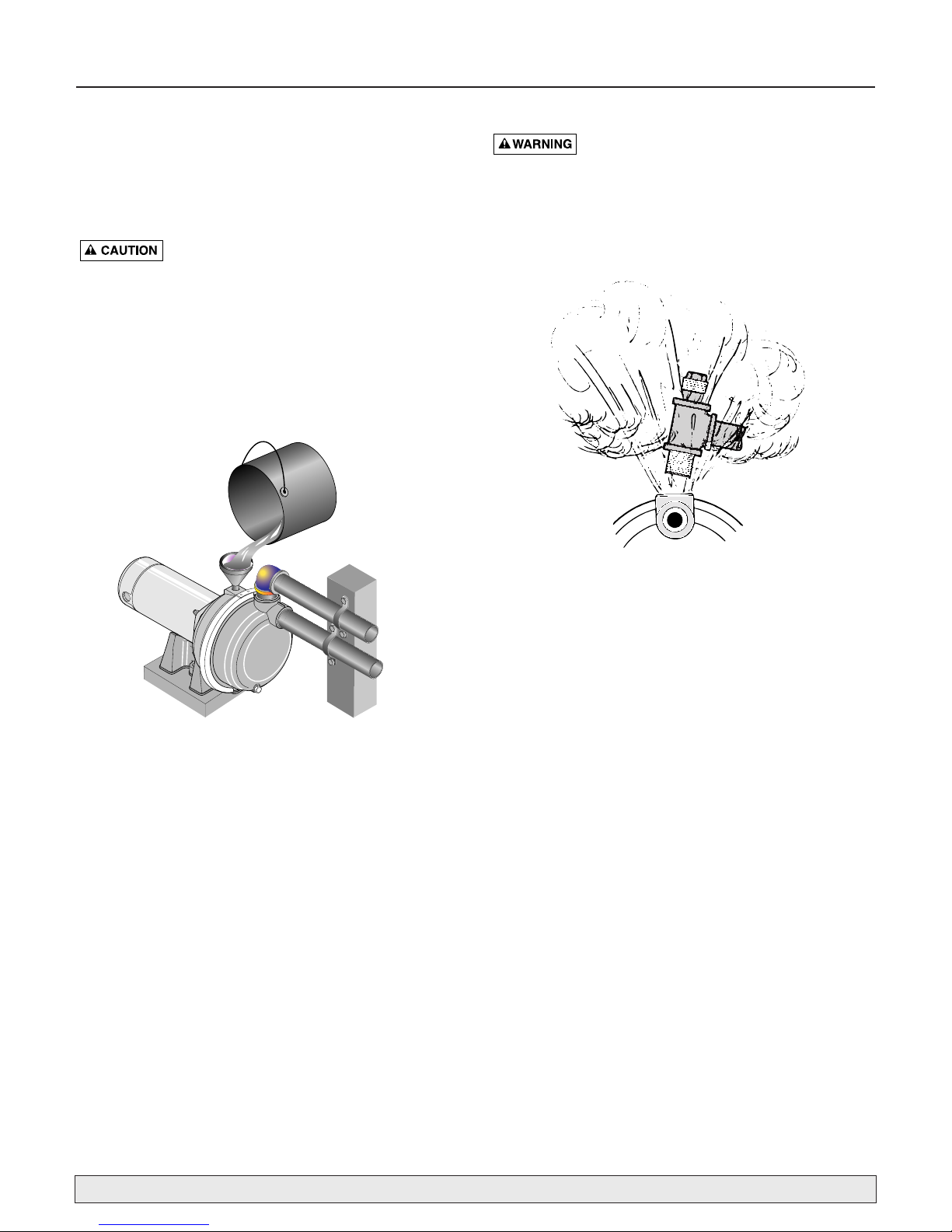
NEVER run pump against closed discharge.
To do so can boil water inside pump, causing hazardous
pressure in unit, risk of explosion and possibly scalding
persons handling pump (Fig. 7). Replace priming plug
with pressure gauge to monitor pressure so that it is not
allowed to exceed maximum pumping pressures according to performance chart.
To prevent explosion be sure discharge (valve, pistol grip
hose nozzle, etc.) is open whenever pump is running.
Monitor pump body and piping temperature. Motor will
warm up; this is normal. If pump body or piping begin to
feel warm to touch, shut off pump and allow system to
cool. Release all pressure in system and refill pump and
piping with cold water.
For parts or assistance, call Flotec Customer Service at 1-800-365-6832
Figure 6: Fill Pump Before Starting
Figure 7: Do Not Run Pump With Outlet Shut Off
1117 0993
P
5
3
-
6
7
1
L
P
647 1293

Troubleshooting 9
For parts or assistance, call Flotec Customer Service at 1-800-365-6832
* (Note:
Stop pump;
then check prime
before looking for
other causes.
Unscrew
priming
plug and see if water
is in priming hole).
SYMPTOM POSSIBLE CAUSE(S) CORRECTIVE ACTION
Motor will not run. Disconnect switch is off. Be sure switch is on.
Fuse is blown or circuit breaker tripped Replace fuse or reset circuit breaker.
Starting switch is defective. DISCONNECT POWER; Replace starting switch.
Wires at motor are loose, Refer to instructions on wiring (Page 6). DISCONNECT POWER; check and
disconnected, or wired incorrectly. tighten all wiring.
Motor runs hot and Motor is wired incorrectly Refer to instructions on wiring.
overload kicks off or
Voltage is too low Check voltage being supplied to motor. Install heavier wiring if wire size is
motor does not run
too small (See Electrical / Wiring Chart).
and only hums.
Motor runs but no Pump in new installation did In new installation:
water is delivered* not pick up prime through:
1. Improper priming. 1. Re-prime according to instructions.
2. Air leaks. 2. Check all connections on suction line, with soapy water or
shaving cream.
3. Leaking foot valve or check valve. 3. Replace foot valve or check valve.
4. Pipe size too small. 4. Re-pipe using size of suction and discharge ports on pump.
Pump has lost prime through: In installation already in use:
1. Air leaks. 1. Check all connections on suction line and shaft seal with soapy water.
2. Water level below suction pipe inlet. 2. Lower suction line into water and re-prime. If receding water level
in well exceeds 25’ (7.6M), a deep well pump is needed.
Impeller is plugged. Clean impeller.
Check valve or foot valve is stuck shut. Replace check valve or foot valve.
Pipes are frozen. Thaw pipes. Bury pipes below frost line. Heat pit or pump house.
Foot valve and/or strainer are Raise foot valve and/or strainer above bottom of water source.
buried in sand or mud. Clean foot valve and strainer.
*Pump does not Water level in well is lower than A deep well jet will be needed if your well is more than 25’ (7.6M)
deliver water to full estimated. depth to water.
capacity.
Steel piping (if used) is corroded or Replace with plastic pipe where possible, otherwise with new steel pipe.
limed, causing excess friction.
Piping is too small in size. Re-pipe using size of suction and discharge ports on pump.
Pump not being supplied with Add additional well points.
enough water.
Pump leaks Clamp loose. STOP PUMP, tighten clamp nut 1-2 turns. Alternately tighten and tap on
around clamp. clamp with mallet to seat O-Ring. Do not overtighten.
Capacitor voltage may be hazardous. To discharge capacitor, hold insulated handle screwdriver BY THE HANDLE and short capacitor
terminals together. Do not touch metal screwdriver blade or capacitor terminals. If in doubt, consult a qualified electrician.

Repair Parts 10
For parts or assistance, call Flotec Customer Service at 1-800-365-6832
Part Names
1. Motor
2. Slinger
3. Priming Plug
4. Seal Plate
5 O-Ring
6. Shaft Seal
7. Impeller
8. Diffuser
9. #8-32x1" Screw
† Lockwasher*
10. Diffuser O-Ring
11. Clamp
12. Pump Body
13. Drain Plug
14. Base
15. Motor Pad
4
3
13
12
Seal Plate,
Diffuser, and
Pump Body for
Model FP5182-01
Models
FP5192-01
FP5162-01
FP5172-01
FP5182-01
L
1
7
6
-
3
5
P
1
2
4
3
5
6
7
8
9
10
13
12
11
14
15
8
Parts in Bold Face
are included in Seal
and Gasket Kit and
in Overhaul Kit.
Parts in
Bold Face
FP5162-08 FP5172-08 FP5182-08
1 HP 1-1/2 HP 2 HP
Key Part 115V/230V 230V
No. Description 60 Hz/1 Ph 60 Hz/1 Ph
1 Motor J218-596PKG J218-601PKG J218-883APKG
4 Seal Plate Complete L176-47P1 L176-47P1 C103-189P
11 "V" Clamp C19-54SS C19-54SS C19-37A
12 Pump Body Front Half C176-53P C176-53P C176-62P
14 Base C4-42P C4-42P C4-42P
• Seal and Gasket Kit FPP5000 FPP5000 FPP5000
Includes Items 2, 5, 6, 9, & 10. See “Part Names,” above.
• Overhaul Kit FPP5001 FPP5002 FPP5008
Includes all items in Seal and Gasket Kit plus Item 7,
impeller,
and 8,
diffuser.
See “Part Names,” above.
Models
FP5192-08
FP5162-08
FP5172-08
FP5182-08
FP5182-08C
Seal Plate, Diffuser,
and Pump Body for
Models FP5182-08
and FP5182-08C
Key Key
No. Description No. Description
1 Motor 9 #8-32x1“ Screw
2 Slinger • Lockwasher*
3 Priming Plug 10 Diffuser O-Ring
4 Seal Plate 11 Clamp
5 O-Ring 12 Pump Body
6 Shaft Seal 13 Drain Plug
7
Impeller
14 Base
8
Diffuser
15 Motor Pad
*Models FP5182-08 and FP5182-08C only.
Parts in Bold Face are included in Seal and Gasket Kit and in Overhaul Kit.
Parts in
Bold Face Italics
are included in Overhaul Kit only.
Part Names
 Loading...