

Flotec FP5100 Owner's Manual
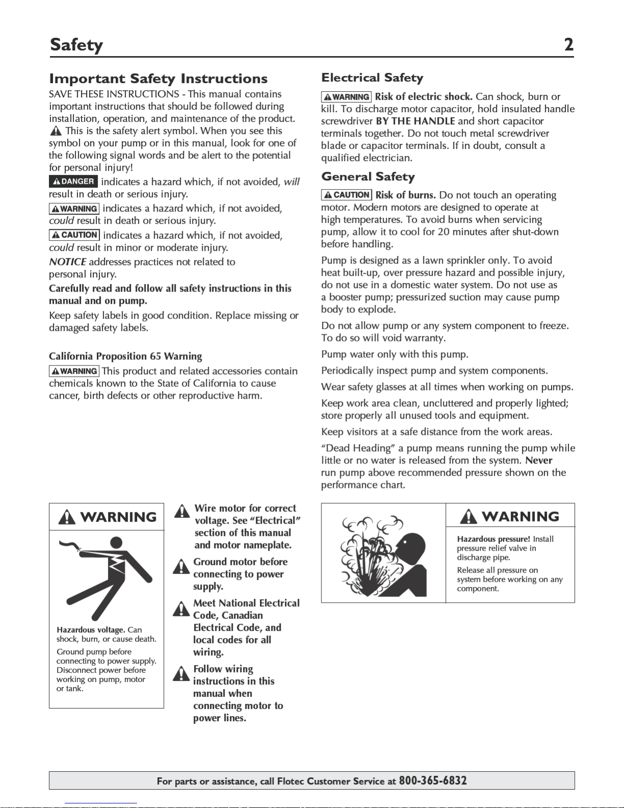

Table of Contents 3
Thank you for purchasing a top quality, factory tested pump.
Page
General Safety .....................................................................................................2
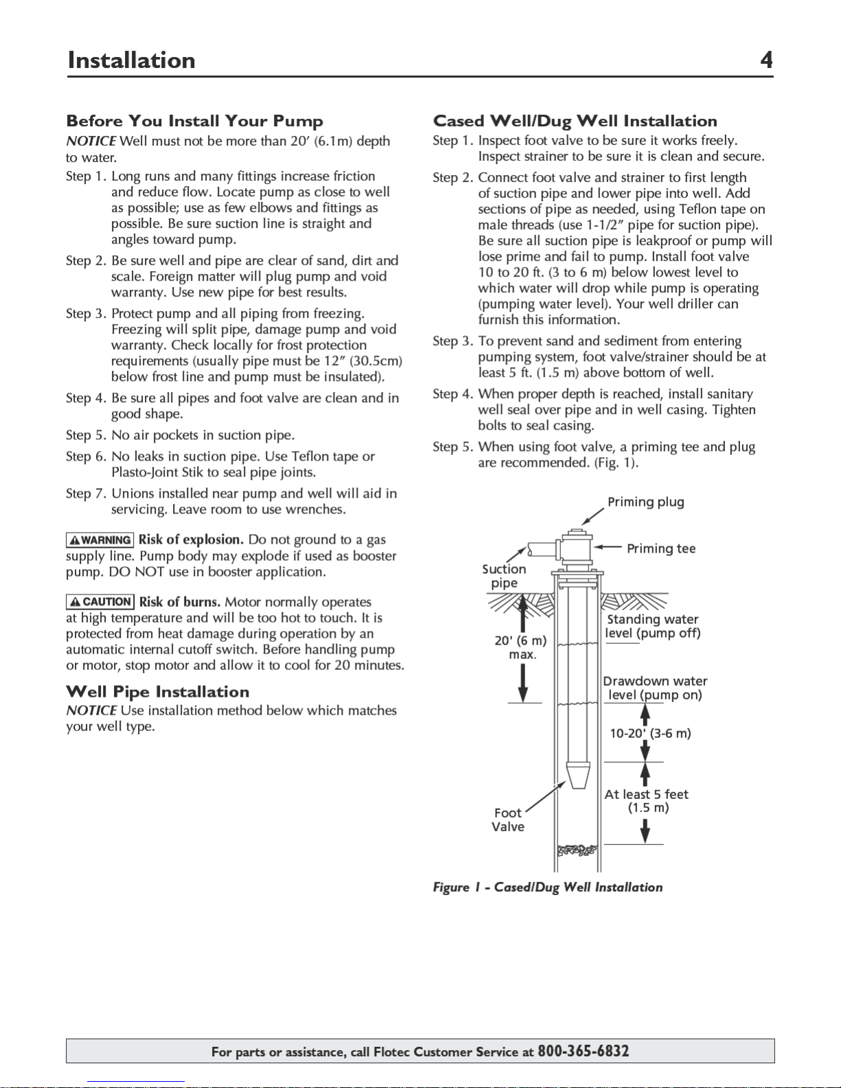
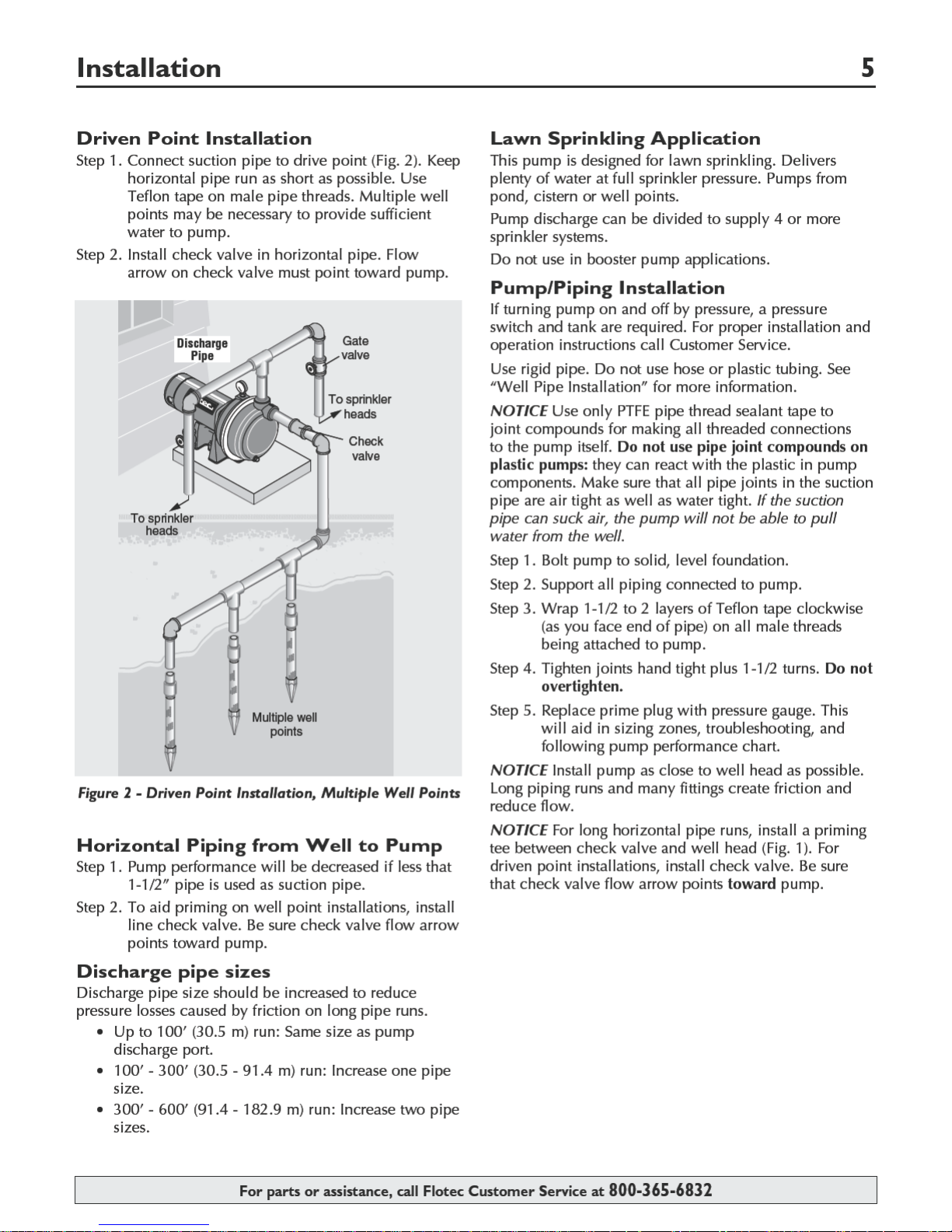
Installation .......................................................................................................4, 5
Electrical ..........................................................................................................6, 7
Operation ............................................................................................................8
Troubleshooting ...................................................................................................9
Repair Parts ......................................................................................................10
Warranty............................................................................................................11
For parts or assistance, call Flotec Customer Service at 800-365-6832
Electrical 7
Wiring
Risk of electric shock. Can shock, burn or kill.
Ground motor before connecting to electrical power
•
supply. Failure to ground motor can cause severe or
fatal electrical shock hazard.
• Do not ground to a gas supply line.
To avoid dangerous or fatal electrical shock, turn
•
OFF power to motor before working on electrical
connections.
Supply voltage must be within ±10% of nameplate
•
voltage. Incorrect voltage can cause fire or damage
motor and voids warranty. If in doubt consult a
licensed electrician.
Use wire size specified in Wiring Chart (below). If
•
possible, connect pump to a separate branch circuit
with no other appliances on it.
Wire motor according to diagram on motor
•
nameplate. If nameplate diagram differs from
diagrams above, follow nameplate diagram.
Step 1. Install, ground, wire and maintain this pump in
accordance with electrical code requirements.
Consult your local building inspector for
information about codes.
Step 2. Provide a correctly fused disconnect switch for
protection while working on motor. Consult
local or national electrical codes for switch
requirements.
Step 3. Disconnect power before servicing motor or
pump. If the disconnect switch is out of sight
of pump, lock it open and tag it to prevent
unexpected power application.
Step 4. Ground the pump permanently using a wire of
the same size as that specified in wiring chart,
below. Make ground connection to green
grounding terminal under motor canopy marked
GRD. or
.
Step 5. Connect ground wire to a grounded lead in the
service panel or to a metal underground water
pipe or well casing at least 10 feet long. Do not
connect to plastic pipe or insulated fittings.
Step 6. Protect current carrying and grounding
conductors from cuts, grease, heat, oil, and
chemicals.
Step 7. Connect current carrying conductors to
terminals L1 and L2 under motor canopy. When
replacing motor, check wiring diagram on motor
nameplate against Figure 4. If the motor wiring
diagram does not match Figure 4, follow the
diagram on the motor.
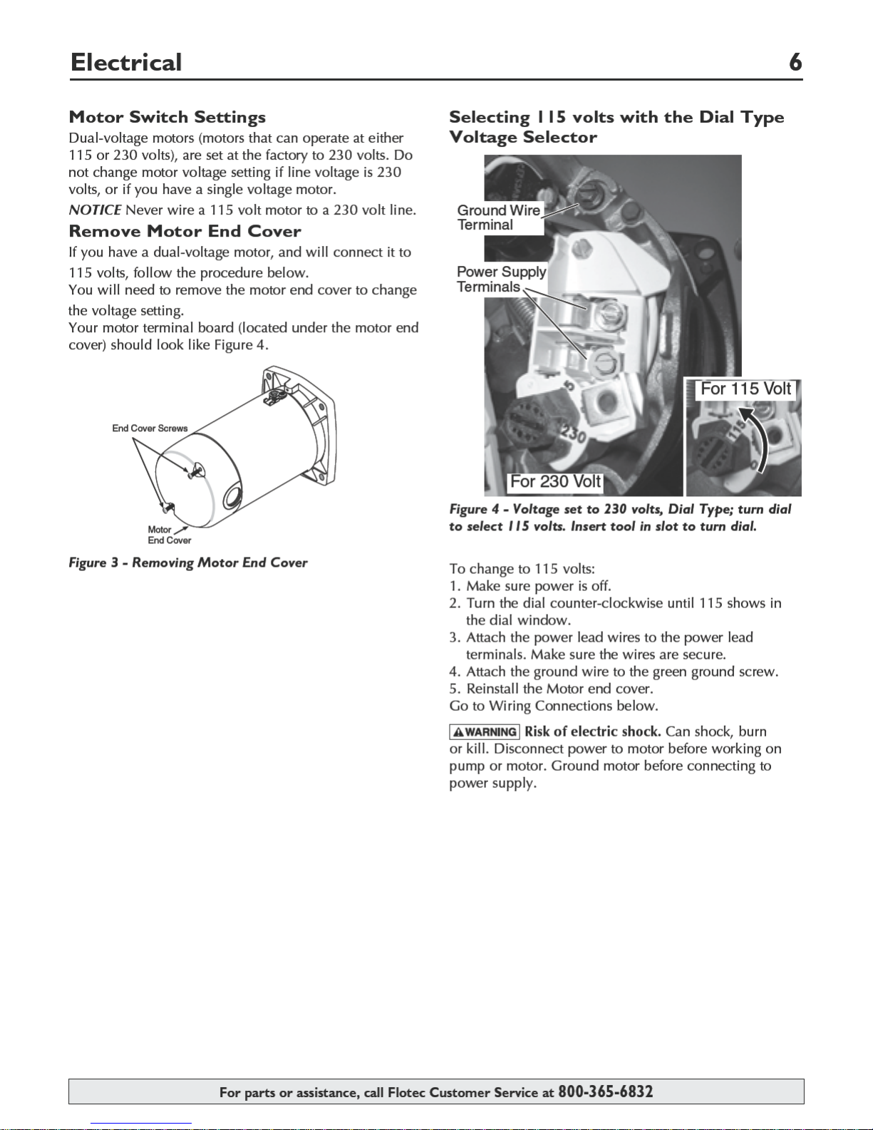
NOTICE 115/230 Volt single phase models are shipped
from factory with motor wired for 230 volts. If power
supply is 115 volts, remove motor canopy and change
switch dial on motor as shown in Figure 4. Do not try to
run motor as received on 115 volt current.
Step 8. Motor has automatic internal thermal overload
protection. If motor has stopped for unknown
reasons, thermal overload may restart it
unexpectedly, which could cause injury or
property damage. Disconnect power before
servicing motor.
Step 9. If this procedure or the wiring diagrams are
confusing, consult a licensed electrician.
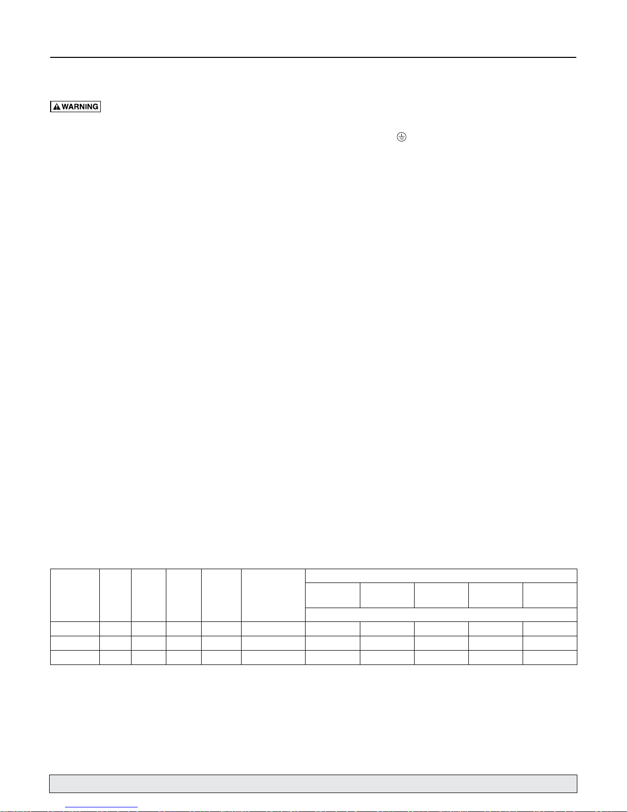
Wiring Chart – Recommended Wire and Fuse Sizes for 115 and 230 volts
Pump
Model
FP5162 1 115/230 14.8/7.4 20/15 12/14 (3/2) 12/14 (3/2) 8/14 (8.4/2) 6/14 (14/2) 6/12 (14/3) 4/10 (21/5.5)
FP5172 1 - 1/2 115/230 19.9/9.9 20/15 10/14 (5.5/2) 10/14 (5.5/2) 8/14 (8.4/2) 6/12 (14/3) 4/10 (21/5.5) 4/10 (21/5.5)
FP5182 2 115/230 24/12 20/15 10/14 (5.5/2) 10/14 (5.5/2) 6/14 (14/2) 6/12 (14/3) 4/10 (21/5.5) 4/10 (21/5.5)
* Duel element or Fusetron time delay fuses recommended for all motor circuits.
HP Volts
Max
Load
Amp
For parts or assistance, call Flotec Customer Service at 800-365-6832
Branch
Rating*
Fuse
Amp
AWG Min. Wire
Size (mm2)
0 - 100
(0 - 30)
Distance in Feet (Meters) From Motor to Supply
101 - 200
(31 - 61)
201 - 300
(62 - 91)
AWG Wire Size (mm
301 - 400
(91 - 122)
2
)
401 - 500
(123 - 152)

Troubleshooting 9
capacitor terminals together. Do not touch metal screwdriver blade or capacitor terminals. If in doubt, consult a qualified electrician.
Motor will not run Disconnect switch is off. Be sure switch is on.
Motor runs hot and
overload kicks off or
motor does not run and
Motor Runs but no water
*(Note: Stop pump;
then check prime before
looking for other causes.
Unscrew priming plug
and see if water is in
*Pump does not deliver
water to full capacity.
Pump leaks around
Risk of electric shock. Can shock, burn or kill.
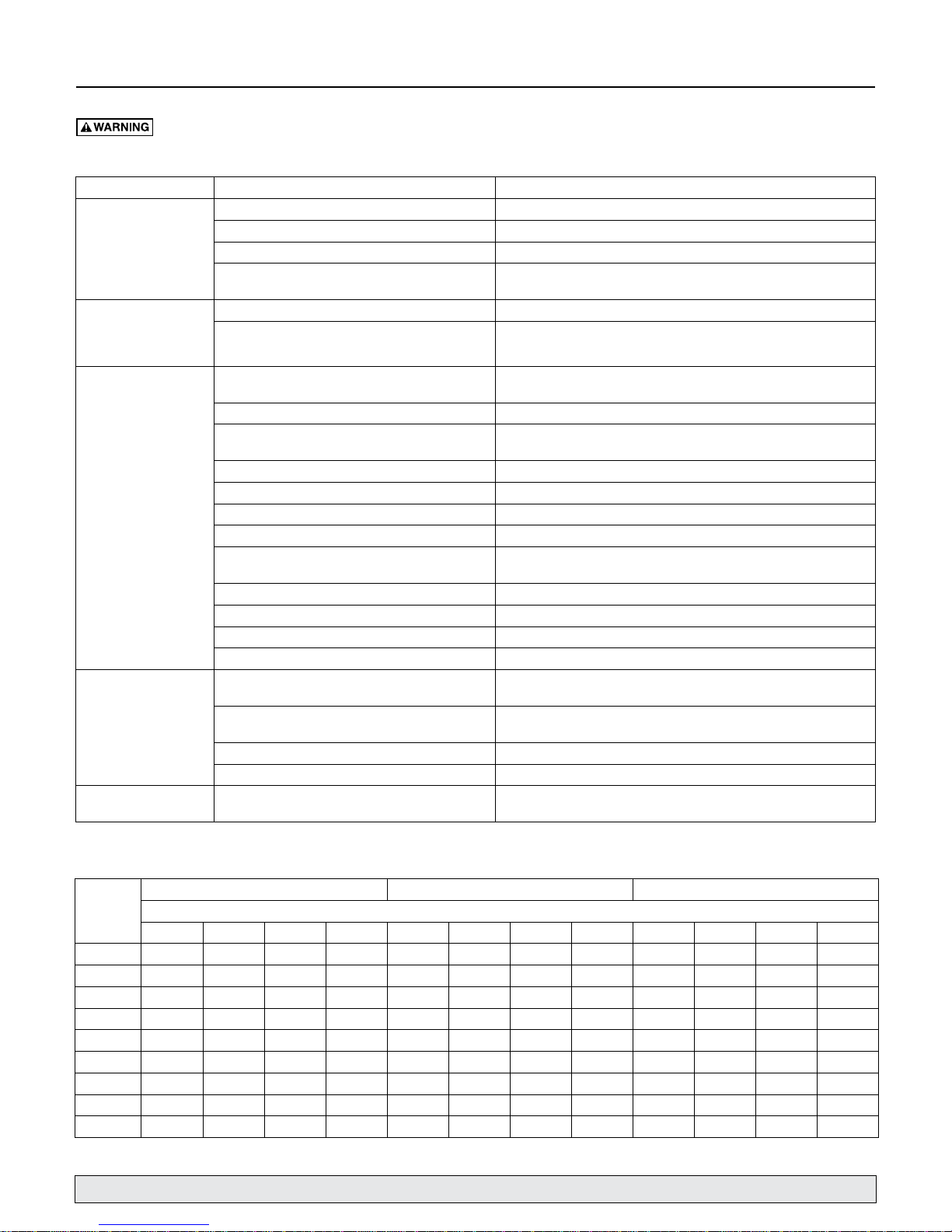
Symptom Possible Cause(s) Corrective Action
Fuse is blown or circuit breaker tripped Replace fuse or reset breaker.
Starting switch is defective. DISCONNECT POWER; Replace starting switch.
Wire ast motor are loose, disconnected, or wired
incorrectly.
Motor is wired incorrectly Refer to instructions on wiring.
Voltage is too low. Check voltage being supplied to motor. Install heavier wiring if wire size is
only hums.
is delivered*
priming hole).
clamp
Pump in new installation did not pick up prime
through:
1. Improper priming 1. Re-prime according to instructions.
2. Air leaks. 2. Check all connections on suction line, with soapy water or shaving
3. Leaking foot valve or check valve 3. Replace foot valve or check valve.
4. Pipe size too small 4. Re-pipe using size of suction and discharge ports on pump.
Pump has lost prime through: In installation already in use:
1. Air leaks 1. Check all connections on suction line and shaft seal with soapywater.
2. Water level bellow suction pipe inlet. 2. Lower suction line into water and re-prime. If receding water level in
Impeller is plugged Clean impeller
Check valve or foot valve is stuck shut Replace check valve or foot valve
Pipes are frozen Thaw pipes. Bury pipes below frost line. Heat pit or pump house.
Foot valve and/or strainer are buried in sand or mud Raise foot valve and/or strainer above bottom of water source.
Water level in well is lower than estimated A deep well jet will be needed if your well is more than 25’ (7.6M) dept to
Steel piping (if used) is corroded or limed, causing
excess friction
Piping is too small in size Re-pipe using size of suction and discharge ports on pump
Pump not being supplied with enough water Add additional well points.
Clamp loose STOP PUMP, tighten clamp nut 1 - 2 turns. Alternately tighten and tap on
To discharge capacitor, hold insulated handle screwdriver BY THE HANDLE and short
Refer to instructions on wiring. DISCONNECT POWER; check and tighten
all wiring.
too small (See Electrical / Wiring Chart)
In new installation:
cream
well exceeds 25’ (7.6M), a deep well pump is needed.
water.
Replace with plastic pipe where possible, otherwise with new steel pipe.
clamp with mallet to seat O-Ring. Do not overtighten.
Discharge
Pressure
PSI (kPa)
10 (69) 55 (208) 49 (185) 48 (181) 45 (170) 67 (254) 61 (231) 56 (212) 46 (174) 69 (261) 64 (242) 65 (246) 62 (235)
15 (103) 51 (193) 46 (174) 45 (170) 44 (166) 66 (250) 58 (220) 55 (208) 45 (170) 65 (246) 62 (235) 60 (227) 57 (215)
20 (138) 45 (170) 42 (159) 39 (148) 37 (140) 61 (231) 56 (212) 54 (204) 44 (166) 59 (223) 56 (212) 54 (204) 52 (197)
25 (172) 38 (144) 35 (132) 32 (121) 29 (110) 55 (208) 52 (197) 51 (193) 43 (163) 52 (197) 50 (189) 48 (181) 46 (174)
30 (207) 31 (117) 28 (106) 24 (90) 20 (76) 48 (181) 45 (170) 44 (166) 37 (14) 47 (178) 45 (170) 42 (159) 40 (151)
35 (241) 23 (87) 19 (72) 16 (60) 11 (42) 39 (147) 37 (140) 34 (129) 28 (106) 42 (159) 38 (144) 35 (132) 32 (121)
40 (276) 17 (64) 13 (49) 8 (30) 33 (125) 27 (102) 20 (76) 11 (42) 34 (129) 30 (113) 27 (102) 23 (87)
45 (310) 18 (68) 14 (53) 8 (30) 25 (95) 18 (68) 13 (49) 10 (38)
50 (345) 14 (53) 7 (26)
All models except FP5182 and FP5182C have discharge and suction size of 1-1/2
5’ (1.5) 10’ (3) 15’ (4.6) 20’ (6.1) 5’ (1.5) 10’ (3) 15’ (4.6) 20’ (6.1) 5’ (1.5) 10’ (3) 15’ (4.6) 20’ (6.1)
FP5162 - 1HP FP5172 - 1 - 1/2 HP FP5182, FP5182C - 2HP
For parts or assistance, call Flotec Customer Service at 800-365-6832
Performance Chart in GPM(LPM)
Height of Pump Above Water in Feet (Meter)
”
NPT. FP5182 and FP5182C have 2” NPT suction and discharge.

 Loading...