

Flotec FP4210, FP4207, FP4205, FP4157, FP4150 Owner’s Manual
OWNER'S MANUAL
®
293 Wright Street, De[avan, Wl 53115
Phone: 1-800-365-6832
Fax: 1-800-526-3757
Web Site: F[otecWater.com
Water
isOur
Business'
Jet Pumps
NOTICE D'UTILISATION
Pompes acc_l_ratrices
MANUAL DEL USUARIO
Bombas de chorro
Shallow Well Pump Models
Pompe Pour Puits Peu Profond
Bomba De Pozo Poco Profundo
FP4155 1/2 HP/ch
FP4157 3/4 HP/ch
FP4150 I HP/ch
installation/Operation/Parts
For further operating_ installation,
or maintenance assistance:
Call 1-800-365-6832
English ............. Pages 2-12
Pompe Pour Puits Profond
Bomba De Pozo Profundo
installation/Fonctionnement/
Pi_ces
Pour plus de renseignements
concernant I'u tilL_ation,
l'installation ou l'entretien,
Composer ie I (800) 365-6832
Fran_ais .......... Pages 13=23
DeepWell Pump Models
FP4205 1/2 HP/ch
FP4207 3/4 HP/ch
FP4210 I HP/ch
instalaci6n/Operaci6n/Piezas
Para mayor informacidn sobre el
funcionamiento, instalacidn o
mantenimiento de/a bomba:
Llame al 1-800-365-6832
Espaffo[ ........... P_ginas 24-34
@2011 FP933 (4/5/11)
Safety 2
Important Safety Instructions
SAVE THESE INSTRUCTIONS -This manual contains
important instructions that should be followed during
installation, operation, and maintenance of the product,
Save this manual for future reference.
_, This is the safety alert symbol. When you see this
symbol on your pump or in this manual, look for one of
the following signal words and be alert to the potential
for personal injury!
indicates a hazard which, if not avoided, will
result in death or serious injury.
E_WARNiNGI indicates a hazard which, if not avoided,
could result in death or serious injury.
E_CAUTION[ indicates a hazard which, if not avoided,
could result in minor or moderate injury.
NOTICE addresses practices not related to personal injury.
Carefully read and follow all safety instructions in this
manual and on pump.
Keep safety labels in good condition.
Replace missing or damaged safety labels.
Electrical Safety
I_WARNINGI Capacitor voltage may be hazardous.
To discharge motor capacitor, hold insulated handle
screwdriver BY THE HANDLE and short capacitor
terminals together. Do not touch metal screwdriver blade
or capacitor terminals. [f in doubt, consult a qualified
electrician.
General Safety
[_ CAUTION1Do not touch an operating motor. Modern
motors are designed to operate at high temperatures. To
avoid burns when servicing pump, allow it to cool for
20 minutes after shut-down before handling.
Do not allow pump or any system component to freeze.
To do so will void warranty.
Pump water only with this pump.
Periodically inspect pump and system components.
Wear safety glasses at all times when working on pumps.
Keep work area clean, uncluttered and properly lighted;
store properly all unused tools and equipment.
Keep visitors at a safe distance from the work areas.
[_WARNING] Pump body may explode if used as a
booster pump unless relief valve capable of passing full
pump flow at 75 psi is installed.
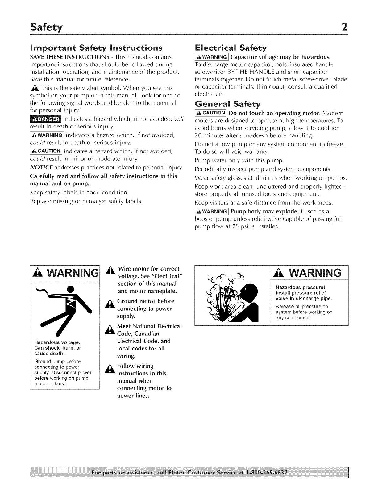
WARNING
Hazardous voltage.
Can shock, burn, or
cause death.
Ground pump before
connecting to power
supply. Disconnect power
before working on pump,
motor or tank.
_, Wire motor for correct
voltage. See "Electrical"
section of this manual
and motor nameplate.
_ round motor before
connecting to power
supply.
,_ Meet Natlona[ Electrical
Code, Canadian
Electrical Code, and
local codes for all
wiring.
_k Follow wiring
instructions in this
manual when
connecting motor to
power lines.
WARNING
Hazardous pressure!
Instal[ pressure relief
valve in discharge pipe.
Release all pressure on
system before working on
any component.

Warranty 3
Retain Original Receipt For Your Records
Limited Warranty
FLOTECwarrantstotheoriginalconsumerpurchaser("Purchaser"or"You")ofitsproductsthattheyarefreefromdefectsinmaterialandworkmanship
foraperiodoftwelve(12)monthsfromthedateoftheoriginalconsumerpurchase.
If,withintwelve(12)monthsfromtheoriginalconsumerpurchase,anysuchproductshallproveto bedefective,itshallberepairedorreplacedat
FLOTEC'soption,subjecttothetermsandconditionssetforthbelow.Theoriginalpurchasereceiptandproductwarrantyinformationlabelarerequired
todeterminewarrantyeligibility.Eligibilityisbasedonpurchasedateof originalproduct- notthedateofreplacementunderwarranty.Thewarrantyis
limitedtorepairor replacementofproductonly- Purchaserpaysall removal,installation,labor,shipping,andincidentalcharges.
Forpartsor troubleshootingassistance,DONOTreturnproducttoyourretailstore.ContactFLOTECCustomerServiceat1-800-365-6832.
Claimsmadeunderthiswarrantyshallbemadebyreturningtheproduct(exceptsewagepumps,seebelow)totheretailoutletwhereitwaspurchased
immediatelyafterthediscoveryofanyallegeddefect.FLOTECwill subsequentlytakecorrectiveactionaspromptlyasreasonablypossible.Norequests
forservicewill beacceptedif receivedmorethan30daysafterthewarrantyexpires.
Sewage Pumps
DONOTreturnasewagepump(thathasbeeninstalled)toyourretailstore.ContactFLOTECCustomerService.Sewagepumpsthathaveseenservice
andbeenremovedcarryacontaminationhazardwiththem.
Ifyoursewagepumphasfailed:
- Wearrubbergloveswhenhandlingthepump;
- Forwarrantypurposes,returnthepump'scordtagandoriginalreceiptofpurchasetotheretailstore;
- Disposeofthepumpaccordingtolocaldisposalordinances.
Exceptions to the Twelve (12) Month Limited Warranty
Product Warranty Period
DrillPump,PitcherPump,In-lineWaterFilterCartridge,Utility Pump(ModelFPOF360AC,FPOFDC) 90 days
1/3 HPSubmersibleSumpPumps,PoolCoverPump(ModelFPOS1790PCA),UtilityPump(ModelFPOS4100X),Condensate 2Years
Pump(ModelFPCP-2OULST),IntelliPump(ModelFPOS1775A),Back-upSumpPumpSystem(ModelFP2800DCC)
4" SubmersibleWellPumps,1/2 HPSubmersibleSumpPumps,1/3 HPSumpPumpModels(FPSC2200A-10,FPSC2250A-10) 3Years
Pre-OhargeWaterSystemTank(FP7100Series),1/2 HPSumpPump(ModelsFPSC3200A-10,FPSC3250A-10),Submersible 5Years
SolidsHandlingPumps(ModelsFPSE9000,E75STVT),SubmersibleSumpPumps(ModelsESOTLT,ESOVLT,E75VLT,
EIOOELT,FPSC5OOOA)
Floodmate®7000(ModelFPOS6OOOA),PedestalSumpPump(ModelFPPSS5000),SewageEjector(ModelFPSE3601A), Lifetime
SubmersibleSewagePump(ModelFPSES2700A),Utility Pump(ModelFPSC1725X),SubmersibleSumpPump(Model
FPSC4550A-10)
General Terms and Conditions
Youmustpayall laborandshippingchargesnecessaryto replaceproductcoveredbythiswarranty.Thiswarrantydoesnotapplytothefollowing:
(1)actsofGod;(2)productswhich,in FLOTEC'ssolejudgement,havebeensubjecttonegligence,abuse,accident,misapplication,tampering,or
alteration;(3)failuresduetoimproperinstallation,operation,maintenanceorstorage;(4)atypicalor unapprovedapplication,useorservice;(5)failures
causedbycorrosion,rustorotherforeignmaterialsinthesystem,oroperationatpressuresinexcessofrecommendedmaximums.
ThiswarrantysetsforthFLOTEC'ssoleobligationandpurchaser'sexclusiveremedyfordefectiveproducts.
FLOTECSHALLNOTBELIABLEFORANYCONSEQUENTIAL,INCIDENTAL,ORCONTINGENTDAMAGESWHATSOEVER.
THEFOREGOINGWARRANTIESAREEXCLUSIVEANDINLIEUOFALLOTHEREXPRESSANDIMPLIEDWARRANTIES,INCLUDINGBUTNOTLIMITED
TOTHEIMPLIEDWARRANTIESOFMERCHANTABILITYANDFITNESSFORA PARTICULARPURPOSE.THEFOREGOINGWARRANTIESSHALLNOT
EXTENDBEYONDTHEDURATIONPROVIDEDHEREIN.
Somestatesdonotallowtheexclusionorlimitationofincidentalor consequentialdamagesorlimitationsonhowlonganimpliedwarrantylasts,sothe
abovelimitationsorexclusionsmaynotapplyto You.ThiswarrantygivesYouspecificlegalrightsandYoumayalsohaveotherrightswhichvaryfrom
statetostate.
FLOTEC. 293 Wright Street • Delavan, Wl U.S.A. 53115
Phone: 1-800-365-6832 " Fax: 1-800-526-3757
Web Site: FIotecWater.com

Installation 4
Process A. Determine the Depth of
YourWell
Shallow wells are less than 25 feet to water; deep wells are up
to 70 feet to waten Tie a small but heavy weight to the end of
a piece of string (be sure there is enough string; some wells are
very deep). J.ower the weight into the well until it reaches the
bottom. Take up the slack and mark the string at ground level.
Pull the weight out of the well and measure from the bottom of
the weight to the ground level mark. This is the depth of your
well. Subtract five feet from the depth of your well. This number
should not exceed the maximum rated depth for your pump. If
it does, it will greatly hinder or prevent the proper operation of
the pump.
Process B. Correctly Select Your Pump
Voltage
[_WARNING[ Hazardous voltage. Disconnect power to pump
before working on pump or motor. Disconnect pump from
power source before changing the pump voltage. To change the
voltage, the selector switch is located underneath the plastic
access cover on top of the motor. To access the switch, remove
the eight screws holding the plastic coven To change the voltage
setting, slide the switch as shown until desired voltage is visible
on the switch. The voltage number that appears is the voltage
setting for the pump. Be sure the switch is completely engaged.
Replace the cover and secure it with the eight screws.
VOLTAGE SELECTION DIRECTIONS
Warning!
Disconnect pump from power
source before servicing or
handling pump.
Be sure that incoming power
supply is same as voltage
selector switch setting.
Wiring Your Pump
I_kWARNING] Hazardous voltage. Disconnect power to pump
before working on pump or match Disconnect pump from
power before servicing or handling pump. Remove the cover
from the pressure switch. Connect the bare copper ground to
the ground screw in the pressure switch. Connect the power
supply to the terminals marked "Line" in the diagram below.
____ fTo Motor
Ground
Connections -_
From Line
5907 1108
Piping
Plastic- PVC pipe is shown in the illustrations, but galvanized
steel pipe may be used if desired. All piping must be clean and
free of all foreign matter to prevent clogging. ALL JOINTS AND
CONNECTIONS IN THE WE[_[. ASSEMBLY MUST BE AIRTIGHT.
Even a pinhole leak will prevent the proper operation of
the pump (this is the most common problem). Use thread
compound on all threaded joints unless specified otherwise.
slide switch as shown
To change voltage settings
until desired voltage is
visible on switch.
Be sure switch is completely
engaged.
Replace capacitor housing cover
and secure cover with screws.
Do not overtighten screws.
Wiring Chart - Recommended Wire And Fuse Sizes
Distance In Feet(Meters) From Motor To Supply
0- 100 101 - 200 201 - 300 301 - 400
Model HP Volts
Motor
FP4155 1/2 115/230
FP4157 3/4 115/230
FP4150 1 115/230
FP4205 1/2 115/230
FP4207 3/4 115/230
FP4210 1 115/230
Nameplate
Amps
8.5/4.2
11.0/5.5
12.0/6.0
7.0/3.5
11.0/5.5
11.0/5.5
Branch Fuse
Rating Amp
15/15
20/15
20/15
15/15
20/15
20/15
(0- 30) (31 - 61) (62 - 91) (92 - 122)
14/14(2/2)
12/14(3/2)
12/14(3/2)
14/14(2/2)
12/14(3/2)
12/14(3/2)
AWG Wire Size (mmO
12/14(3/2)
10/14(5.5/2)
10/14(5.5/2)
12/14(3/2)
10/14(5.5/2)
10/14(5.5/2)
10/14(5.5/2)
8/14(8.4/2)
8/14(8.4/2)
10/14(5.5/2)
8/14(8.4/2)
8/14(8.4/2)
8/14(8.4/2)
6/14(14/2)
6/14(14/2)
10/14(5.5/2)
6/14( 14/2 )
6/14(14/2)
Process C. 1. install a shallow well pump
(FP4155, FP4157, FP4150)
Draining For Servicing or For Winter
The pump should be drained before it is disconnected for
servicing or if it is in danger of freezing. To drain:
Remove drain plug from bottom of pump case.
• Remove discharge tee to vent the pump.
• Drain a[[ piping to a point 3 feet (1 meter) below
ground [eve[.
For we[is 25 feet or less in depth, the 1/2 HP FP4155, 3/4 HP
FP4157 and 1 HP FP4150 pumps are recommended. However,
the 1/2 HP FP4205, 3/4 HP FP4207, and 1 HP FP4210
convertible pumps may be adapted to shallow wells with an
ejector kit.
General Materials Required
• One can PVC cement (read instructions carefully)
• One can thread compound (read instructions carefully)
• One 1-1/4" footva[ve
• Two male 1-1/4" PVC adapters
• Enough rigid 1-1/4" PVC pipe and couplings to reach from
bottom of we[[ to pump
• One we[[ sea[ with vent plug
• One 1-1/4" PVC elbow
• One discharge tee
One pressure gauge
• One male 1" PVC adapter
• Enough rigid 1" PVC pipe to reach from pump to pressure
tank to service line
• One female 1" PVC adapter
• One 1" tank cross (for diaphragm tanks)
Two 1/4" plugs
• One 1/2" drain cock
• One 10"x 1" nipple
In addition to General Materials, for the FP4205,
FP4207, or FP4210 Convertible only
One ejector I<it; includes ejector, venturi tube, gasket, bolts,
plug, tubing, and fittings.
Tools needed for all pump installations
Pipe wrench, pipe damp, crescent wrench, slot screwdriver,
24-tooth hacksaw, knife or round file.
Reminder: All joints and connections must be airtight. A single pinhole leak will prevent the
proper operation of the pump. Use thread compound on all threaded connections unless
specified otherwise.
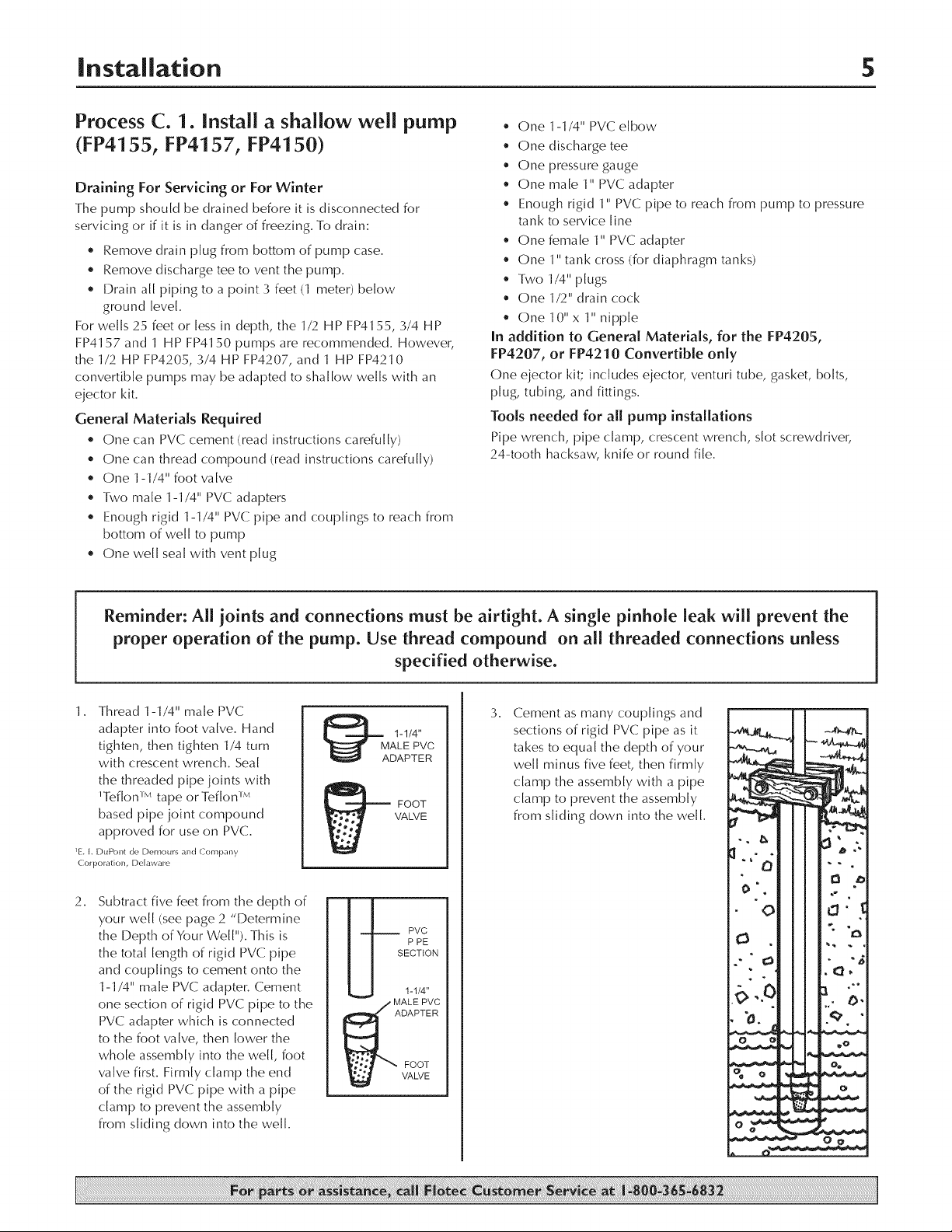
1. Thread 1-1/4" male PVC
adapter into foot valve. Hand
tighten, then tighten 1/4 turn
with crescent wrench. Seal
the threaded pipe joints with
'Teflon ''_ tape or Teflon ''_
based pipe joint compound
approved for use on PVC.
1E. L DuPout de Demours aud (ompany
( orporatiou, Ddaware
2.
Subtract five feet from the depth of
your well (see page 2 "Determine
the Depth of Y0ur We[["). This is
the total length of rigid PVC pipe
and couplings to cement onto the
1-1/4" male PVC adapter. Cement
one section of rigid PVC pipe to the
PVC adapter which is connected
to the foot valve, then lower the
whole assembly into the we[[, foot
valve first. Firmly (_-[amp the end
of the rigid PVC pipe with a pipe
damp to prevent the assembly
from sliding down into the we[[.
M 1-1/4 '
ALE PVC
DAPTER
VALVE
_ FOOT
m
P PE
SECTION
_ VC
1-I/4"
MAL E PVC
DAPTER
FOOT
VALVE
3. Cement as many couplings and
sections of rigid PVC pipe as it
takes to equal the depth of your
well minus five feet, then firmly
clamp the assembly with a pipe
clamp to prevent the assembly
from sliding down into the well.
0 O _0
% o o.
Installation 6
10.
Process C, continued.
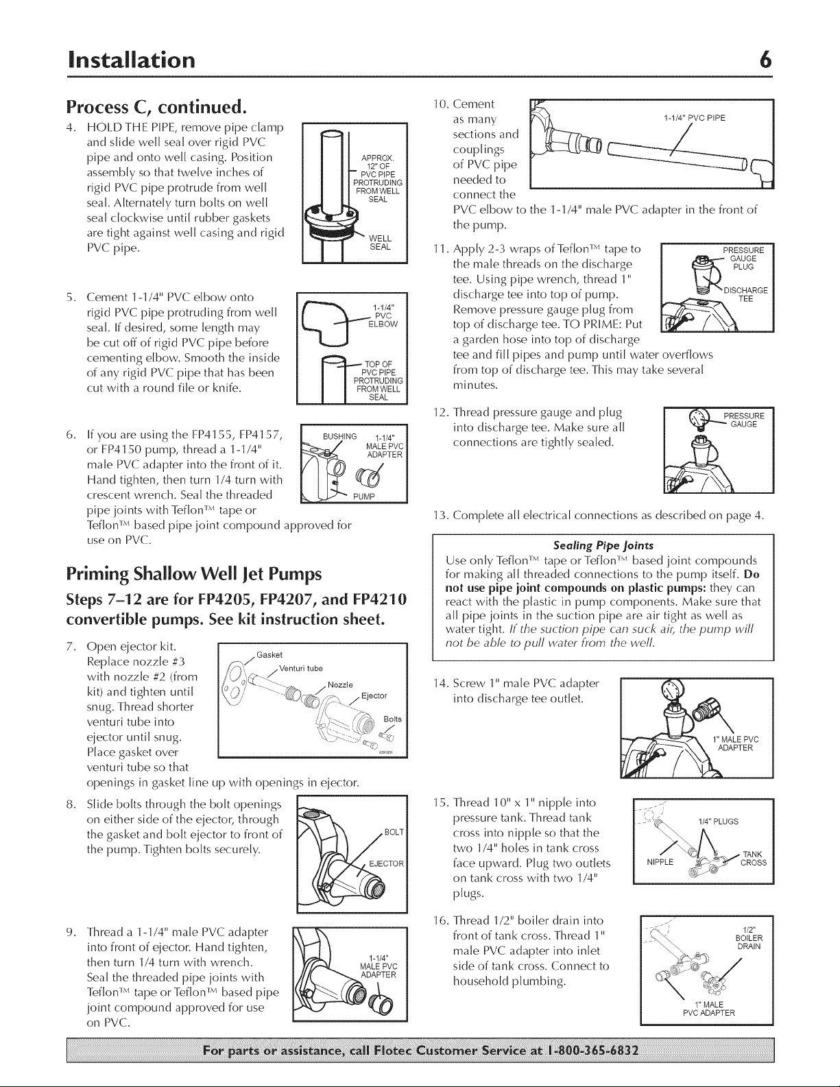
4. HOI.DTHE PIPE, remove pipe clamp
and slide well seal over rigid PVC
pipe and onto well casing. Position
assembly so that twelve inches of
rigid PVC pipe protrude from well
seal. Alternately turn bolts on well
seal clockwise until rubber gaskets
are tight against well casing and rigid
PVC pipe.
2. Cement 1-1/4" PVC elbow onto
rigid PVC pipe protruding from well
_E 1-1/4"
seal. If desired, some length may
be cut off of rigid PVC pipe before
cementing elbow. Smooth the inside
of any rigid PVC pipe that has been
cut with a round file or knife.
6.
If you are using the FP4155, FP4157,
or FP4150 pump, thread a 1-1/4"
male PVC adapter into the front of it.
Hand tighten, then turn 1/4 turn with
crescent wrench. Sea[ the threaded
pipe joints with Teflon _'* tape or
Teflon i.,, based pipe joint compound approved for
use on PVC.
Priming Shallow Well Jet Pumps
Steps 7-12 are for FP4205, FP4207, and FP4210
convertible pumps. See kit instruction sheet.
7.
Open ejector kit.
Replace nozzle #3
with nozzle #2 (from
kit) and tighten until
snug. Thread shorter
venturi tube into
ejector until snug.
Place gasket over
venturi tube so that
openings in gasket line up with openings in ejector.
8.
Slide bolts through the bolt openings
on either side of the ejector, through
the gasket and bolt ejector to front of
the pump. Tighten bolts securely.
Gasket
_J
_O BOLT
APPROX.
12" OF
-- PVC PiPE
PROTRUDING
FROM WELL
SEAL
_WELL
SEAL
PVC
LBOW
TOP OF
PVC PiPE
OTRUDING
OMWELL
SEAL
BUSHING 1-1/4"
PUMP
Nozzle
TOR
Cement
as many
sections and
couplings
of PVC pipe
needed to
connect the
PVC elbow to the 1-1/4" male PVC adapter in the front of
the pump.
11.
Apply 2-3 wraps of Teflon _'* tape to
the male threads on the discharge
tee. Using pipe wrench, thread 1"
discharge tee into top of pump.
Remove pressure gauge plug from
top of discharge tee. TO PRIME: Put
a garden hose into top of discharge
tee and fill pipes and pump until water overflows
from top of discharge tee. This may take several
minutes.
12.
Thread pressure gauge and plug
into discharge tee. Make sure all
connections are tightly sealed.
13. Complete all electrical connections as described on page 4.
Sealing Pipe Joints
Use only Teflon i.,, tape or Teflon i_, based joint compounds
for making all threaded connections to the pump itself. Do
not use pipe ioint compounds on plastic pumps: they can
react with the plastic in pump components. Make sure that
all pipe joints in the suction pipe are air tight as we[[ as
water tight. If the suction pipe can suck ai;, the pump wift
not be able to puff water from the weft.
14. Screw 1" male PVC adapter
into discharge tee outlet.
15.
Thread 10" x 1" nipple into
pressure tank. Thread tank
cross into nipple so that the
two 1/4" holes in tank cross
face upward. Plug two outlets
NIPPLE
on tank cross with two 1/4"
plugs.
PRESSURE [
GAUGE |
I_ PLUG I
_ DISCHARGE |
GAUGE
PRESSURE I
1/4" PLUGS
9.
Thread a 1-1/4" male PVC adapter
into front of ejector. Hand tighten,
then turn 1/4 turn with wrench.
Seal the threaded pipe joints with
Teflon _* tape or Teflon _'* based pipe
joint compound approved for use
on PVC.
m
I_ 1-1/4"
16.
Thread 1/2" boiler drain into
front of tank cross. Thread 1"
male PVC adapter into inlet
side of tank cross. Connect to
household plumbing.
1"MALE
PVC ADAPTER
1/2"
BOILER
DRAIN
|nstallation 7
Process C, continued,
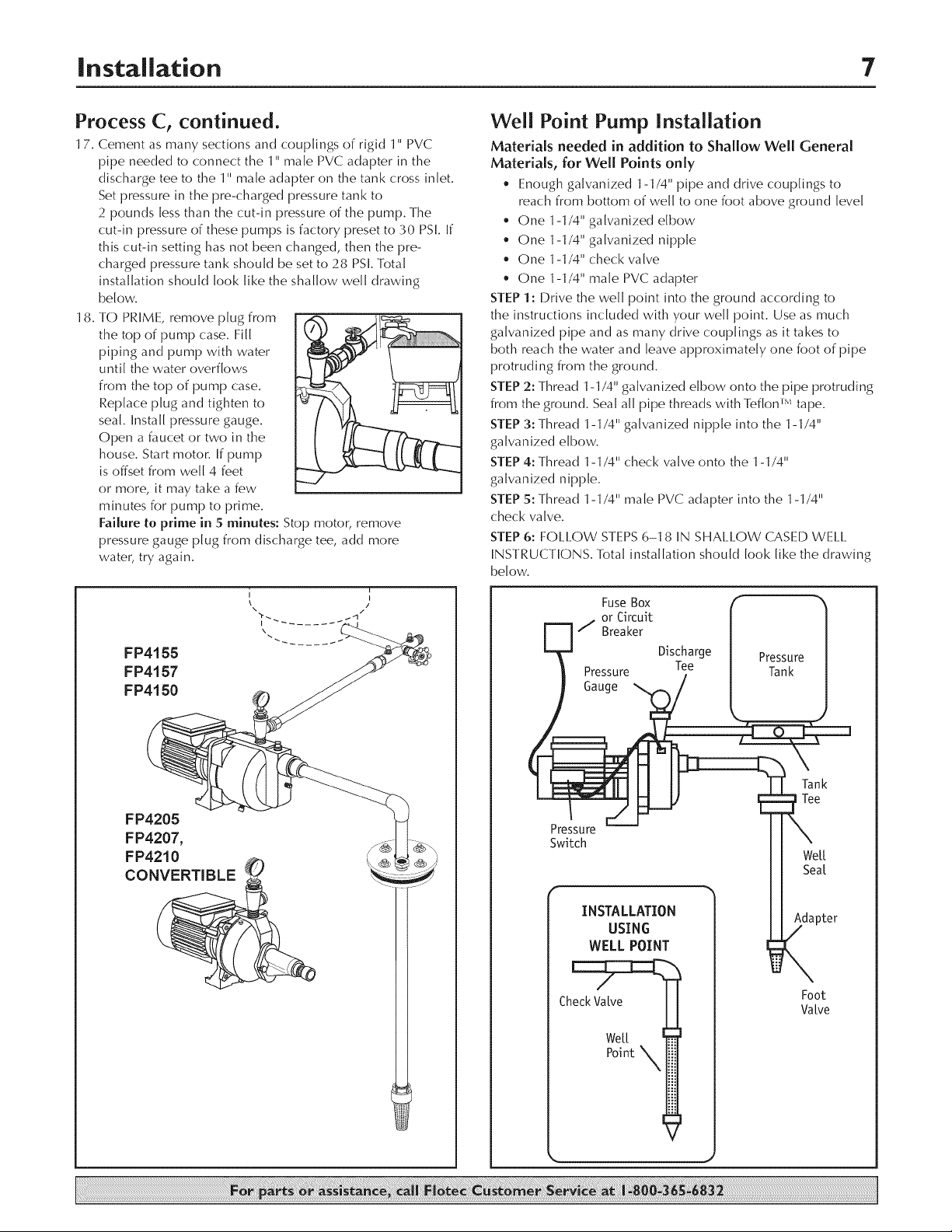
17. Cement as many sections an(] couplings of rigid 1" PVC
pipe needed to connect the 1" male PVC adapter in the
discharge tee to the 1" male adapter on the tank cross inlet.
Set pressure in the pre-charged pressure tank to
2 pounds less than the cut-in pressure of the pump. The
cut-in pressure of these pumps is factory preset to 30 PSI. If
this cut-in setting has not been changed, then the pre-
charged pressure tank should be set to 28 PSI. Total
installation should look like the shallow well drawing
below.
18. TO PRIME, remove plug from
the top of pump case. Fill
piping and pump with water
until the water overflows
from the top of pump case.
Replace plug and tighten to
seal. Install pressure gauge.
Open a faucet or two in the
house. Start motor. If pump
is offset from well 4 feet
or more, it may take a few
minutes for pump to prime.
Failure to prime in 5 minutes: Stop motor, remove
pressure gauge plug from discharge tee, add more
water, try again.
j i
X\ /I
\
FP4155
FP4157
FP4150
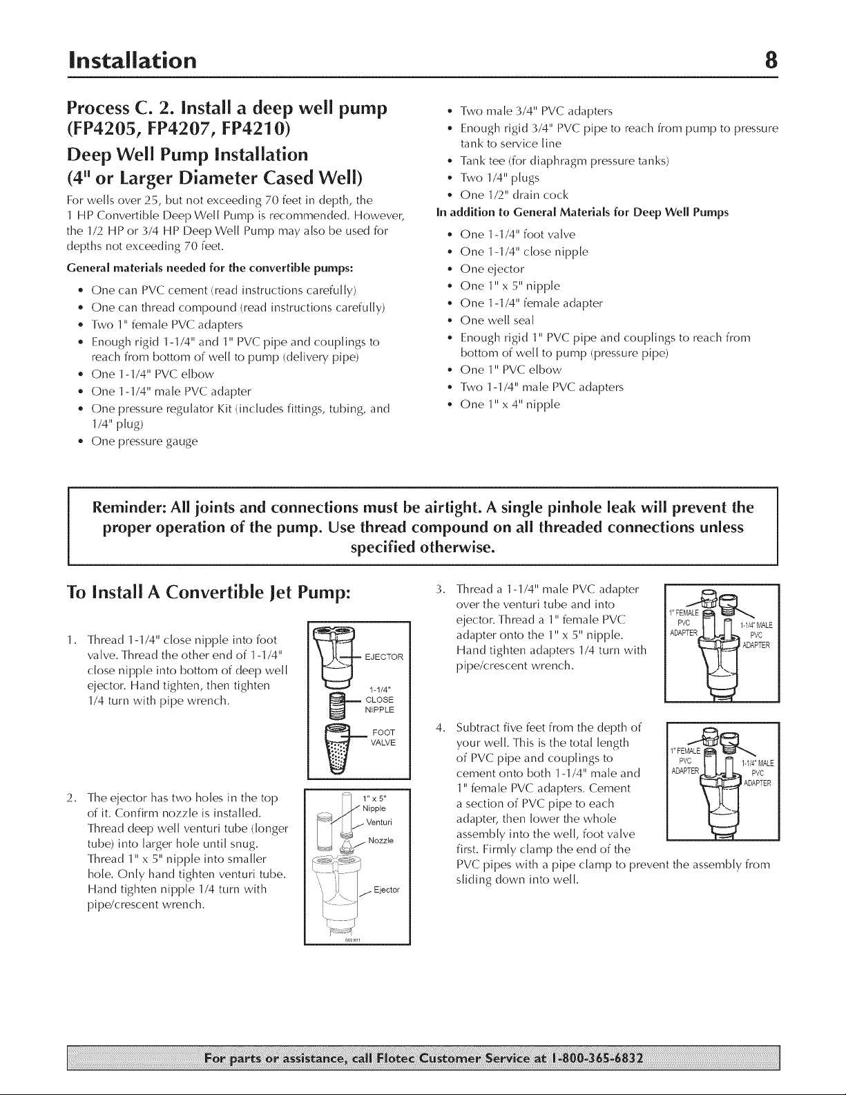
Well Point Pump Installation
Materials needed in addition to Shallow Well General
Materials, for Well Points only
• Enough galvanized 1-1/4" pipe and drive couplings to
reach from bottom of we[[ to one foot above ground [eve[
• One 1-1/4" galvanized elbow
• One 1-1/4" galvanized nipple
• One 1-1/4" check valve
• One 1-1/4" male PVC adapter
STEP 1: Drive the we[[ point into the ground according to
the instructions included with your we[[ point. Use as much
galvanized pipe and as many drive couplings as it takes to
both reach the water and leave approximately one foot of pipe
protruding from the ground.
STEP 2: Thread 1-1/4" galvanized elbow onto the pipe protruding
from the ground. Sea[ all pipe threads with Teflon r'* tape.
STEP 3: Thread 1-1/4" galvanized nipple into the 1-1/4"
galvanized elbow.
STEP 4: Thread 1-1/4" check valve onto the 1-1/4"
galvanized nipple.
STEP 5: Thread 1-1/4" male PVC adapter into the 1-1/4"
check valve.
STEP 6: FOLLOW STEPS 6-1 8 IN SHALLOW CASED WEI.I_
INSTRUCTIONS. Total installation should look like the drawing
below.
or Circuit
/ Breaker
Fuse Box ]
Pressure Tee Tank
Gauge
Discharge Pressure
FP4205
FP4207,
FP4210
CONVERTIBLE
Pressure
Switch
INSTALLATION
WELL POINT
Check Vatve
Tank
Tee
We[[
Sea[
USING
Foot
Valve
Weft
Point X
Installation 8
Process C. 2. install a deep well pump
(FP4205, FP4207, FP4210)
Deep Well Pump Installation
(4" or Larger Diameter Cased Well)
For weLLs over 25, but not exceeding 70 feet in depth, the
1 HP ConvertibLe Deep We[[ Pump is recommended. However,
the 1/2 HP or 3/4 HP Deep We[[ Pump may also be used for
depths not exceeding 70 feet.
Genera[ materials needed for the convertible pumps:
* One can PVC cement (read instructions carefuLLy)
* One can thread compound (read instructions carefuLLy)
* Two 1" female PVC adapters
* Enough rigid 1-1/4" and 1" PVC pipe and couplings to
reach from bottom of we[[ to pump (deLivery pipe)
* One 1-1/4" PVC elbow
* One 1-1/4" male PVC adapter
* One pressure regulator Kit (incLudes fittings, tubing, and
1/4" pLug)
* One pressure gauge
• Two male 3/4" PVC adapters
• Enough rigid 3/4" PVC pipe to reach from pump to pressure
tank to service Line
• Tank tee (for diaphragm pressure tanks)
Two 1/4" pLugs
• One 1/2" drain cock
In addition to Genera[ Materia[s fur Deep Weft Pumps
• One 1-1/4" foot valve
• One 1-1/4" close nipple
• One ejector
• One 1" x 5" nipple
• One 1-1/4" female adapter
• One we[[ sea[
• Enough rigid 1" PVC pipe and couplings to reach from
bottom of well to pump (pressure pipe)
• One 1" PVC elbow
• Two 1-1/4" male PVC adapters
• One 1" x 4" nipple
Reminder: ALl joints and connections must be airtight. A single pinhole Leak wiLL prevent the
proper operation of the pump. Use thread compound on all threaded connections unless
specified otherwise.
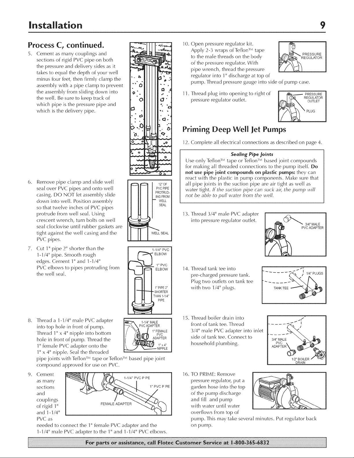
To Install A Convertible Jet Pump:
1.
Thread 1-1/4" close nipple into foot
valve. Thread the other end of 1-1/4"
dose nipple into bottom of deep we[[
ejector. Hand tighten, then tighten
1/4 turn with pipe wrench.
2.
The ejector has two holes in the top
of it. Confirm nozzle is installed.
Thread deep well venturi tube (longer
tube) into larger hole until snug.
Thread 1" x 5" nipple into smaller
hole. Only hand tighten venturi tube.
Hand tighten nipple 1/4 turn with
pipe/crescent wrench.
_ EJECTOR
.... _ Nipple
/ [ _9/Nezzte
_J _A
1-1/4"
NIPPLE
_ CLOSE
._ FOOT
VALVE
i 1"x5"
ve tur,
Ejector
3.
Thread a 1-1/4" male PVC adapter
over the venturi tube and into
ejector. Thread a 1" female PVC
adapter onto the 1" x 5" nipple.
Hand tighten adapters 1/4 turn with
pipe/crescent wrench.
4.
Subtract five feet from the depth of
your we[[. This is the total length
of PVC pipe and couplings to
cement onto both 1-1/4" male and
1" female PVC adapters. Cement
a section of PVC pipe to each
adapter, then lower the whole
assembly into the we[[, foot valve
first. Firmly clamp the end of the
PVC pipes with a pipe clamp to prevent the assembly from
sliding down into well.
ProcessC, continued.
5. Cement as many couplings and
sections of rigid PVC pipe on both
the pressure and delivery sides as it
takes to equal the depth of your we[[
minus four feet, then firmly damp the
assembly with a pipe clamp to prevent
the assembly from sliding down into
the we[[. Be sure to keep track of
which pipe is the pressure pipe and
which is the delivery pipe.
6.
Remove pipe clamp and slide well
seal over PVC pipes and onto well
casing. DO NOT let assembly slide
down into well. Position assembly
so that twelve inches of PVC pipes
protrude from we[[ sea[. Using
crescent wrench, turn bolts on we[[
sea[ clockwise until rubber gaskets are
tight against the we[[ casing and the
PVC pipes.
7.
Cut 1" pipe 2" shorter than the
1-1/4" pipe. Smooth rough
edges. Cement 1" and 1-1/4"
PVC elbows to pipes protruding from
the well seal.
12"OF
PVCPIPE
PROTRUD-
ING FROM
• WELL
SEAL
-LL SEAL
1-1/4" PVC
_ ELBOW
_ ELBOW
r_l 11,, PIPE2"
1" PVC
10.
Open pressure regulator kit.
Apply 2-3 wraps of Teflon v,, tape
PRESSURE
to the male threads on the body
of the pressure regulator. With
pipe wrench, thread the pressure
EGULATOR
regulator into 1" discharge at top of
pump. Thread pressure gauge into side of pump case.
11.
Thread plug into opening to right of
pressure regulator outlet.
OUTLET
Priming Deep Well Jet Pumps
12. Complete all electrical connections as described on page 4.
Sealing Pipe joints
Use only Teflon v'_ tape or Teflon _ based joint compounds
for making all threaded connections to the pump itself. Do
not use pipe ioint compounds on plastic pumps: they can
react with the plastic in pump components. Make sure that
all pipe joints in the suction pipe are air tight as well as
water tight. If the suction pipe can suck air, the pump will
not be able to puff water hem the well.
13. Thread 3/4" male PVC adapter
into pressure regulator outlet.
14, Thread tank tee into
pre-charged pressure tank.
Plug two outlets on tank tee
with two 1/4" plugs.
...... ,' ,4"PLUCS
8.
Thread a 1-1/4" male PVC adapter
into top hole in front of pump.
VCADAPTER
Thread 1" x 4" nipple into bottom
hole in front of pump. Thread the
1" female PVC adapter onto the
t -1/4" MALE I
1" x 4" nipple. Seal the threaded
pipe joints with Teflon L'*tape or Teflon L'*based pipe joint
compound approved for use on PVC.
9. Cement
as many
sections
and
couplings
of rigid 1" FEMALEADAPTER
and 1-1/4"
PVC as
needed to connect the 1" female PVC adapter and the
1-1/4" male PVC adapter to the 1" and 1-1/4" PVC elbows.
1-1/4" PVC P PE
1" FEMALE
PVC
DAPTER
1"x4"
NIPPLE
1" PVC P PE
15. Thread boiler drain into
front of tank tee. Thread
3/4" male PVC adapter into inlet
side of tank tee. Connect to
household plumbing.
'4'pv ;LE,
ADAPTERX_ @FJ_b..
1/2" BOILER _
16. TO PRIME: Remove
pressure regulator, put a
garden hose into the top
of the pump discharge
and fill and pump
with water until water
overflows from top of
pump. This may take several minutes. Put regulator back
on pump.
._ i#
DRAIN
Process C, continued.
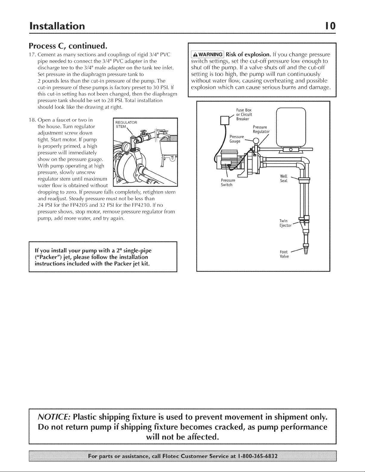
17. Cement as many sections and couplings of rigid 3/4" PVC
pipe needed to connect the 3/4" PVC adapter in the
discharge tee to the 3/4" male adapter on the tank tee inlet.
Set pressure in the diaphragm pressure tank to
2 pounds less than the cut-in pressure of the pump. The
cut-in pressure of these pumps is factory preset to 30 PSI. If
this cut-in setting has not been changed, then the diaphragm
pressure tank should be set to 28 PSI. Total installation
should look like the drawing at right.
18. Open a faucet or two in
the house. Turn regulator STEM
adjustment screw down N
tight. Start motor. If pump
is properly primed, a high
pressure will immediately
show on the pressure gauge.
With pump operating at high
pressure, slowly unscrew
regulator stem until maximum
water flow is obtained without
dropping to zero. If pressure falls completely, retighten stem
and readjust. Steady pressure must not be less than
24 PSI for the FP4205 and 32 PSI for the FP4210. If no
pressure shows, stop motor, remove pressure regulator from
pump, add more water, and try again.
REGULATOR
[_WARNING] Risk of explosion. [f you change pressure
switch settings, set the cut-off pressure low enough to
shut off the pump. If a valve shuts off and the cut-off
setting is too high, the pump will run continuously
without water flow, causing overheating and possible
explosion which can cause serious burns and damage.
FuseBOX ( '_
_=._/ or Circuit [ [
U Br0aker | |
/ Pressure | |
] ReguLator | |
Pressure / ] [
/ Ga'uge _ L_
Pressure Sea[
Switch
Twin
If you install your pump with a 2" slngle-pipe
("Packer") jet, please follow the installation
Foot
Valve
instructions included with the Packer jet kit.
NOTICE: Plastic shipping fixture is used to prevent movement in shipment only.
Do not return pump if shipping fixture becomes cracked, as pump performance
will not be affected.
Troubleshooting II
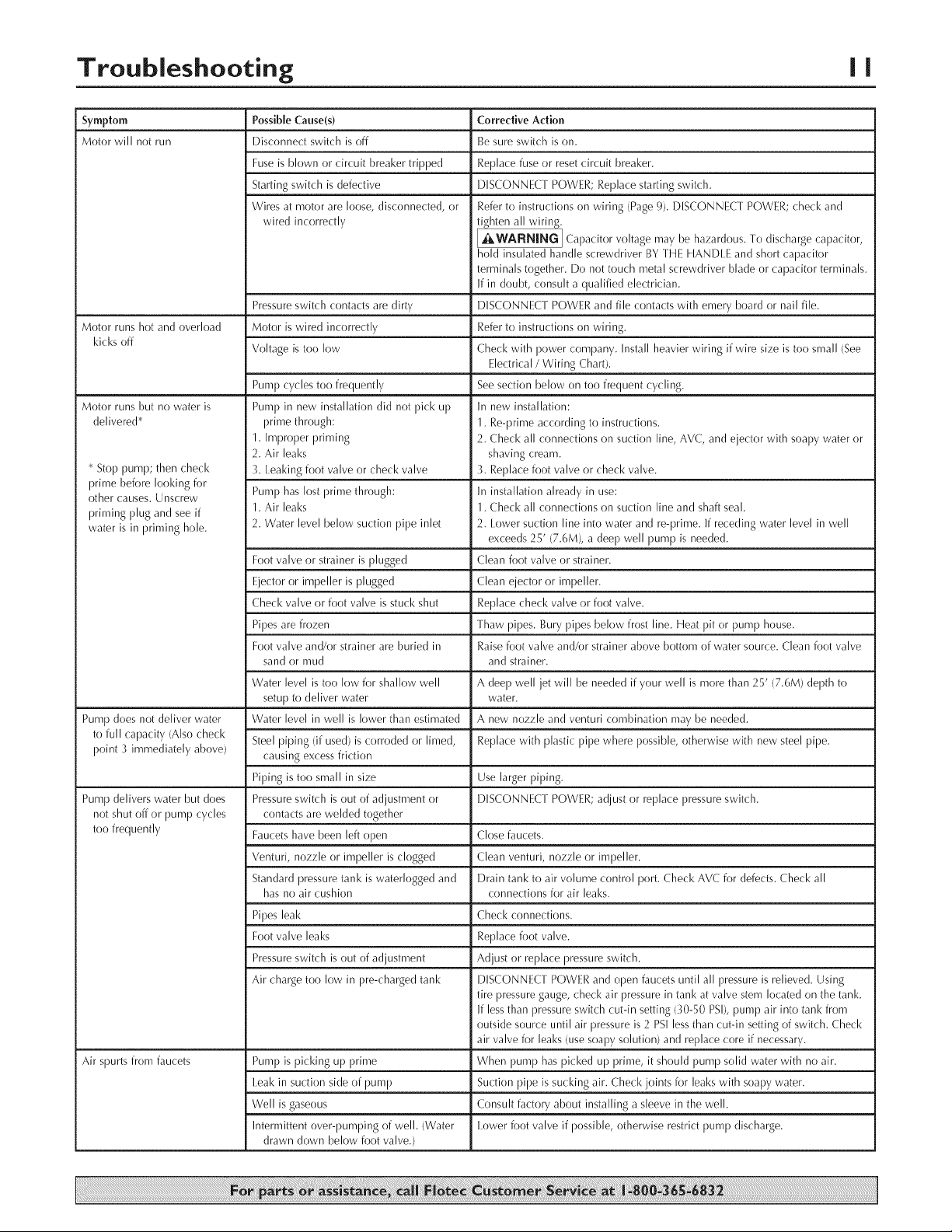
Symptom
Motor will not run
Possible Cause(s)
Disconnect switch is off
Fuse is blown or circuit breaker tripped
Starting switch is defective
Wires at motor are loose, disconnected, or
wired incorrectly
Pressureswitch contacts aredirty
Motor runs hot and overload Motor is wired incorrectly
kicksoff
Motor runs but no water is
delivered*
* Stop pump; then check
prime before looking for
other causes. Unscrew
priming plug and see if
water is in priming hole.
Pump does not deliver water Water level in well is lower than estimated
to full capacity (Also check
point _¢immediately above)
Pump delivers water but does Pressure switch is out of adjustment or DISCONNECT POWER; adjust or replace pressure switch.
not shut off or pump cycles contacts are welded together
too frequently Faucets have been left ol)en Close faucets.
Air spurts from faucets Pump is picking up prime When pump has picked up prime, it should pump solid water with no air.
Voltage is too low
Pump cycles too frequently
Pump in new installation did not pick up
prime through:
1. Improper priming
2. Air leaks
_¢.Iealdng foot valve or check valve
Pump has lost prime through:
1. Air leaks
2. Water level below suction pipe inlet
Foot valve or strainer is plugged
Ejector or impeller is plugged
Check valve or foot valve is stuck shut
Pipes are frozen
Foot valve and/or strainer are buried in
sand or mud
Water level is too low for shallow well
setup to deliver water
Steel piping (if used) is corroded or limed,
causing excess friction
Piping is too small in size Use larger piping.
Venturi, nozzle or impeller is clogged Clean venturi, nozzle or impeller.
Standard pressure tank is waterlogged and Drain tank to air volume control port. Check AVC for defects. Check all
has no air cushion connections for air leaks.
Pipes leak Check connections.
Foot valve leaks Replace foot valve.
Pressure switch is out of adjustment Adjust or replace pressure switch.
Air charge too low in pre-charged tank DISCONNEC[ POWER and (}pen faucets until all pressure is relieved. Using
leak in suction side of pump Suction pipe is sucking air. Check joints for leaks with soapy water.
Well is gaseous Consult factory about installing a sleeve in the well.
Intermittent over-pumping of well. (Water lower foot valve if possible, otherwise restrict pump discharge.
drawn down below foot valve.)
Corrective Action
Be sure switch is on.
Replace fuse or reset circuit breaker.
DISCONNECT POWER; Replace starting switch.
Refer to instructions on wiring (Page 9). DISCONNECT POWER; check and
tighten all wiring.
I ,_WARNING I Cal)acitor voltage may be hazardous. To discharge capacitor,
hold insulated handle screwdriver BY IHE HANDLE and short capacitor
terminals together. Do not touch metal screwdriver blade or capacitor terminals.
If in doubt, consult a qualified electrician.
DISCONNECT POWER and file contacts with emery board or nail file.
Refer to instructions on wiring.
Check with power company. Install heavier wiring if wire size is too small (See
Electrical / Wiring Chart).
See section below on too frequent cycling.
In new installation:
1. Re-prime according to instructions.
2. Check all connections on suction line, AVC, and ejector with soapy water or
shaving cream.
_¢.Replace foot valve or check valve.
In installation already in use:
1. Check all connections on suction line and shaft seal.
2. lower suction line into water and re-prime. If receding water level in well
exceeds 25' (7.6M), a deep well pump is needed.
Clean foot valve or strainer.
Clean ejector or impeller.
Replace check valve or foot valve.
Thaw pipes. Bury pipes below frost line. Heat pit or pump house.
Raise foot valve and/or strainer above bottom of water source. Clean foot valve
and strainer.
A deep well jet will be needed if your well is more than 25' (7.6M) depth to
water.
A new nozzle and venturi combination may be needed.
Replace with plastic pipe where possible, otherwise with new steel pipe.
tire pressure gauge, check air pressure in tank at valve stem located on the tank.
If less than pressure switch cut-in setting (30-50 PSI), pump air into tank from
outside source until air pressure is 2 PSI less than cut-in setting of switch. Check
air valve for leaks/use soapy solution) and replace core if necessary.
 Loading...