

Flotec FP4800, FP4000, FP4100 Owner's Manual
OWNER’S MANUAL
Shallow Well Jet Pumps/
Tank Systems
NOTICE D’UTILISATION
Systems de pompes enfonte
montées sur réservoir pour
puisage en eau peu profonde
MANUAL DEL USUARIO
Sistemas de bombas tip “jet”/
tanques para pozos poco profundos
Installation/Operation/Parts
For further operating, installation,
or maintenance assistance:
Call 1-800-365-6832
English . . . . . . . . . . . . . . Pages 2-13
Installation/Fonctionnement/Pièces
Pour plus de renseignements
concernant l’utilisation,
l’installation ou l’entretien,
Composer le
1 (800) 365-6832
Français . . . . . . . . . . . Pages 14-25
Instalación/Operación/Piezas
Para mayor información sobre el
funcionamiento, instalación o
mantenimiento de la bomba:
Llame al 1-800-365-6832
Español . . . . . . . . . . .Paginas 26-36
FP312 (Rev. 6/25/05)
Series FP4000 Series FP4100
Series FP4800
P.O. Box 342, Delavan, WI 53115
Phone:
1-800-365-6832
Fax:
1-800-526-3757
E-Mail:
info@flotecwater.com
Web Site:
http://www.flotecwater.com
®
®
Safety 2
For parts or assistance, call Flotec Customer Service at 1-800-365-6832
READ AND FOLLOW
SAFETY INSTRUCTIONS!
This is the safety alert symbol. When you see this
symbol on your pump or in this manual, look for
one of the following signal words and be alert to the
potential for personal injury:
warns about hazards that will cause serious
personal injury, death or major property damage if
ignored.
warns about hazards that can cause serious
personal injury, death or major property damage if
ignored.
warns about hazards that will or can cause
minor personal injury or property damage if ignored.
The label NOTICE indicates special instructions which
are important but not related to hazards.
Carefully read and follow all safety instructions in this
manual and on pump.
Keep safety labels in good condition.
Replace missing or damaged safety labels.
ELECTRICAL SAFETY
Capacitor voltage may be hazardous. To dis-
charge motor capacitor, hold insulated handle screwdriver
BY THE HANDLE and short capacitor terminals together.
Do not touch metal screwdriver blade or capacitor terminals. If in doubt, consult a qualified electrician.
GENERAL SAFETY
Do not touch an operating motor. Modern
motors are designed to operate at high temperatures. To
avoid burns when servicing pump, allow it to cool for 20
minutes after shut-down before handling.
Do not allow pump or any system component to freeze.
To do so will void warranty.
Pump water only with this pump.
Periodically inspect pump and system components.
Wear safety glasses at all times when working on pumps.
Keep work area clean, uncluttered and properly lighted;
store properly all unused tools and equipment.
Keep visitors at a safe distance from the work areas.
Pump body may explode if used as a
booster pump unless relief valve capable of passing full
pump flow at 75 psi is installed.
WARNING
Hazardous pressure!
Install pressure relief
valve in discharge pipe.
Release all pressure on
system before working on
any component.
WARNING
Hazardous voltage.
Can shock, burn, or
cause death.
Ground pump before
connecting to power
supply. Disconnect power
before working on pump,
motor or tank.
Wire motor for correct
voltage. See “Electrical”
section of this manual and
motor nameplate.
Ground motor before
connecting to power
supply.
Meet National Electri-
cal Code, Canadian
Electrical Code, and local
codes for all wiring.
Follow wiring instruc-
tions in this manual
when connecting motor to
power lines.

Table of Contents 3
Thank you for purchasing a top quality, factory tested pump.
Page
General Safety .....................................................................................................2
Warranty..............................................................................................................3
Installation ........................................................................................................4,5
Connecting Discharge Piping...............................................................................6
Electrical...........................................................................................................7,8
Preparing To Start The Pump................................................................................9
Repair Parts .................................................................................................10-12
Troubleshooting..................................................................................................13
ATTACH ORIGINAL RECEIPT HERE FOR WARRANTY CONSIDERATION.
FLOTEC warrants to the original consumer purchaser (“Purchaser”) of its products that they are free from defects in material or workmanship.
If within twelve (12) months from the date of the original consumer purchase any such product shall prove to be defective, it shall be repaired or
replaced at FLOTEC’s option, subject to the terms and conditions set forth below.Your original receipt of purchase is required to determine warranty eligibility.
Exceptions to the Twelve (12) Month Warranty
Product Warranty Period
Drill Pump, Pitcher Pump, In-line Water Filter Cartridge 90 days
1/3 HP Submersible Sump Pumps, INTELLIPUMP (Model FP0S1775A)
2 Years
Back-up Sump Pump System (Model FP2800DCC)
4" Submersible Well Pumps, 1/2 HP Submersible Sump Pumps
3 Years
Models FPSC2200A-10 and FPSC2250A-10
Pre-Charge Water System Tank, Models FPSC3200A-10 and FPSC3250A-10 5 Years
Floodmate®7000 (Model FP0S6000A), Ironmate®(Model FPSC4550A)
Sewage Ejector (Model FPSE3601A), Pedestal Sump Pump (Model FPPSS5000) Lifetime
Utility Pump (Model FPSC1725X), Submersible Sump Pump (Model FPSC4550A-10)
General Terms and Conditions
Purchaser must pay all labor and shipping charges necessary to replace product covered by this warranty.This warranty shall not apply to
acts of God, nor shall it apply to products which, in the sole judgement of FLOTEC, have been subject to negligence, abuse, accident, misapplication, tampering, alteration; nor due to improper installation, operation, maintenance or storage; nor to other than normal application,
use or service, including but not limited to, operational failures caused by corrosion, rust or other foreign materials in the system, or operation at pressures in excess of recommended maximums.
Requests for service under this warranty shall be made by returning the defective product to the Retail outlet or to FLOTEC as soon as possible after the discovery of any alleged defect. FLOTEC will subsequently take corrective action as promptly as reasonably possible. No
requests for service under this warranty will be accepted if received more than 30 days after the term of the warranty.
This warranty sets forth FLOTEC’s sole obligation and purchaser’s exclusive remedy for defective products.
FLOTEC SHALL NOT BE LIABLE FOR ANY CONSEQUENTIAL, INCIDENTAL, OR CONTINGENT DAMAGES WHATSOEVER.
THE FOREGOING WARRANTIES ARE EXCLUSIVE AND IN LIEU OF ALL OTHER EXPRESS WARRANTIES. IMPLIED WARRANTIES,
INCLUDING BUT NOT LIMITED TO THE IMPLIED WARRANTIES OF MERCHANTABILITY AND FITNESS FOR A PARTICULAR PURPOSE, SHALL NOT EXTEND BEYOND THE DURATION OF THE APPLICABLE EXPRESS WARRANTIES PROVIDED HEREIN.
Some states do not allow the exclusion or limitation of incidental or consequential damages or limitations on how long an implied warranty
lasts, so the above limitations or exclusions may not apply to you. This warranty gives you specific legal rights and you may also have other
rights which vary from state to state.
FLOTEC • P.O. Box 342 • Delavan, WI U.S.A. 53115
Phone: 1-800-365-6832 • Fax: 1-800-526-3757
E-Mail: info@flotecwater.com • Web Site: http://www.flotecwater.com
Installation 4
REPLACING AN OLD PUMP
Hazardous voltage. Disconnect power to pump before work-
ing on pump or motor.
Step 1. Drain and remove the old pump. Check the old pipe for scale, lime,
rust, etc., and replace it if necessary.
Step 2. Install the pump in the system. Make sure that all pipe joints in the
suction pipe are air-tight as well as water tight.
If the suction pipe
can suck air, the pump will not be able to pull water from the well.
Step 3. Adjust the pump mounting height so that the plumbing connections
do not put a strain on the pump body. Support the pipe so that the
pump body does not take the weight of piping or fittings.
You have just completed the well plumbing for your new shallow
well jet pump. Please go to Page 6 for discharge pipe and tank connections.
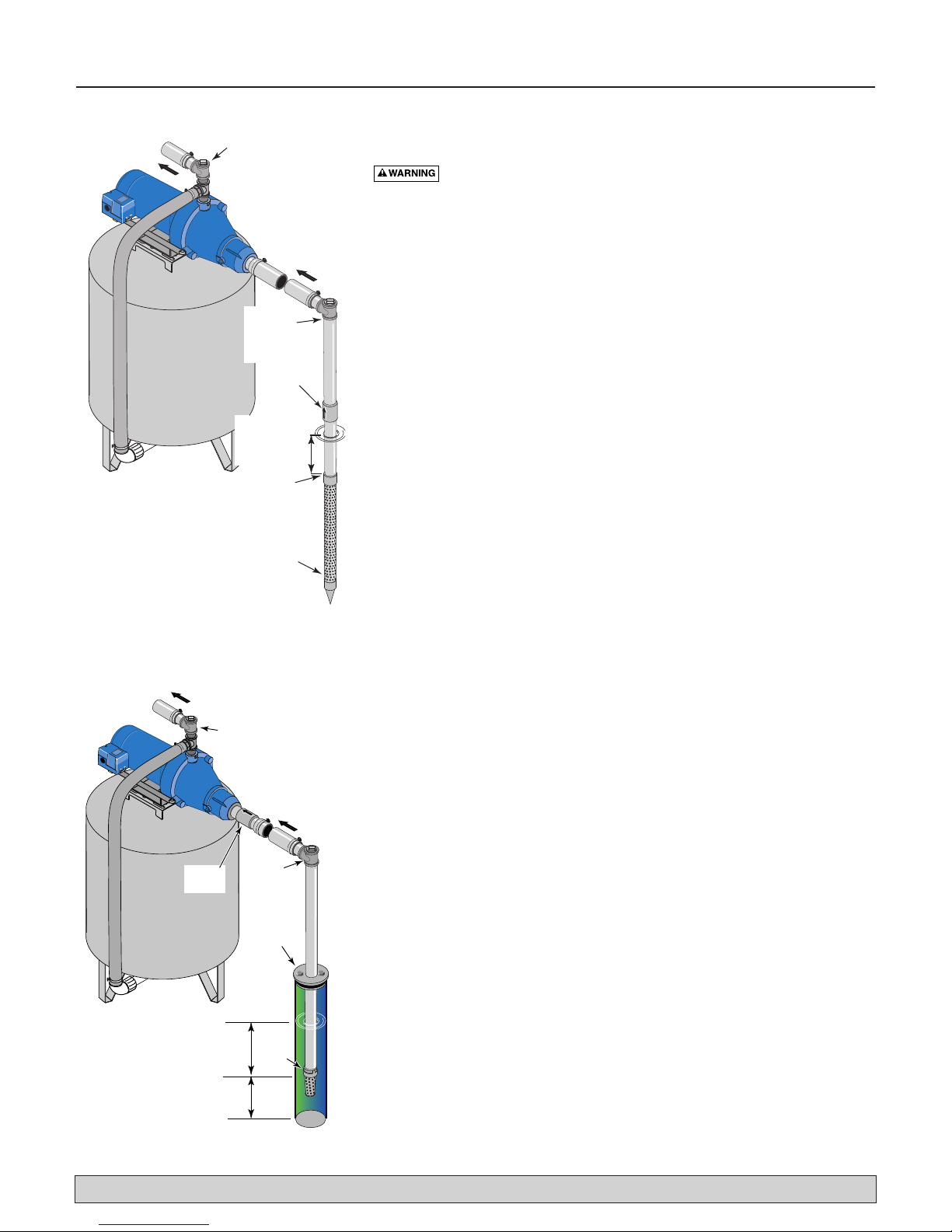
WELL POINT (DRIVEN POINT) INSTALLATION
(Figure 1)
Step 1. Drive the well, using “drive couplings” and a “drive cap”. “Drive
fittings” are threaded all the way through and allow the pipe ends to
butt against each other so that the driving force of the maul is carried by the pipe and
not
by the threads. The ordinary fittings found
in hardware stores are not threaded all the way through the fitting
and can collapse under impact. “Drive fittings” are also smoother
than standard plumbing fittings, making ground penetration easier.
Step 2. Mount the pump as close to the well as possible.
Step 3. Use the fewest possible fittings (especially elbows) when connecting
the pipe from the well point to the pump suction port. The suction
pipe should be at least as large as the suction port on the pump
(include a check valve if your pump is not equipped with one – see
Figure 1). Support the pipe so that there are no dips or sags in the
pipe, so it doesn’t strain the pump body, and so that it slopes slightly upward from the well to the pump (high spots can cause air
pockets which can air lock the pump). Seal the suction pipe joints
with teflon tape or a teflon based pipe joint compound. Joints must
be air- and water-tight.
If the suction pipe can suck air, the pump
cannot pull water from the well.
If one well point does not supply
enough water, consider connecting two or three well points to one
suction pipe.
You have just completed the suction piping for your new shallow
well jet pump. Please go to Page 6 for discharge pipe and tank connections.
CASED WELL INSTALLATION, 2" OR LARGER
CASING (Figure 2)
Step 1. Mount the pump as close to the well as possible.
Step 2. Assemble the foot valve, strainer, and well pipe (see Figure 2). Make
sure that the foot valve works freely.
Step 3. Lower the pipe into the well until the strainer is five feet above the
bottom of the well. It should also be at least 10 feet below the well’s
water level
while the pump is running
in order to prevent the pump
from sucking air. Install a sanitary well seal.
For parts or assistance, call Flotec Customer Service at 1-800-365-6832
Figure 1: Driven Point Installation
Figure 2: Cased Well Installation
To Household
Water System
Not
to
1861 0205
Pump Priming
Tee with Plug
or Gauge
Priming
Tee and
Plug
Check
Valve
Drive point
below water
level
Drive
Coupling
Drive
Point
Scale
To Household
Water System
Pump Priming
Tee with Plug
or Gauge
Suction Pipe
From Well
Check
Valve
1862 0795
Not
to
Scale
10'
Min.
5–10'
Priming
Tee and
Plug
Sanitary
Well Seal
Foot
Valve

Installation 5
Step 4. Install a priming tee, priming plug, and suction pipe to the pump
(see Figure 2). Connect the pipe from the well to the pump suction
port, using the fewest possible fittings – especially elbows – as fittings increase friction in the pipe (however, include a foot valve –
see Figure 2). The suction pipe should be at least as large as the
suction port on the pump. Use teflon tape or a teflon-based pipe
joint compound on threaded pipe joints. Support the pipe so that
there are no dips or sags in the pipe, so it doesn’t strain the pump
body, and so that it slopes slightly upward from the well to the
pump (high spots can cause air pockets which can air lock the
pump). Seal the suction pipe joints with teflon tape or a teflon
based pipe joint compound. Joints must be air- and water-tight.
If
the suction pipe can suck air, the pump cannot pull water from the
well.
You have just completed the suction piping for your new shallow
well jet pump. Please go to Page 6 for discharge pipe and tank
connections.
INSTALLATION FOR SURFACE WATER (Figure 3)
Step 1. The pump should be installed as close to the water as possible,
with the fewest possible fittings (especially elbows) in the suction
pipe. The suction pipe should be at least as large as the suction port
on the pump.
Step 2. Assemble a foot valve and suction pipe (see Figure 3). Make sure
that the foot valve works freely. Use teflon tape or a teflon-based
pipe joint compound on threaded pipe joints. Protect the foot valve
assembly from fish, trash, etc, by installing a screen around it (see
Figure 3).
Step 3. Lower the pipe into the water until the strainer is five feet above the
bottom. It should also be at least 10 feet below the water level in
order to prevent the pump from sucking air.
Step 4. Install a priming tee, priming plug, and suction pipe to the pump
(see Figure 3). Support the pipe so that there are no dips or sags in
the pipe, so it doesn’t strain the pump body, and so that it slopes
slightly upward from the well to the pump (high spots can cause air
pockets which can air lock the pump). Seal the suction pipe joints
with teflon tape or a teflon based pipe joint compound. Joints must
be air- and water-tight.
If the suction pipe can suck air, the pump
cannot pull water from the well.
You have just completed the plumbing for your new shallow well jet
pump. Please go to Page 6 for discharge pipe and tank connections.
For parts or assistance, call Flotec Customer Service at 1-800-365-6832
Figure 3: Surface Water Installation
To Household
Water System
1863 0205
Pump Priming
Tee with Plug
or Gauge
Suction Pipe
From Water
Source
Priming
Tee and
Plug
Not
to
Scale
10'
Min.
5–10'
Foot
Val ve
Screen
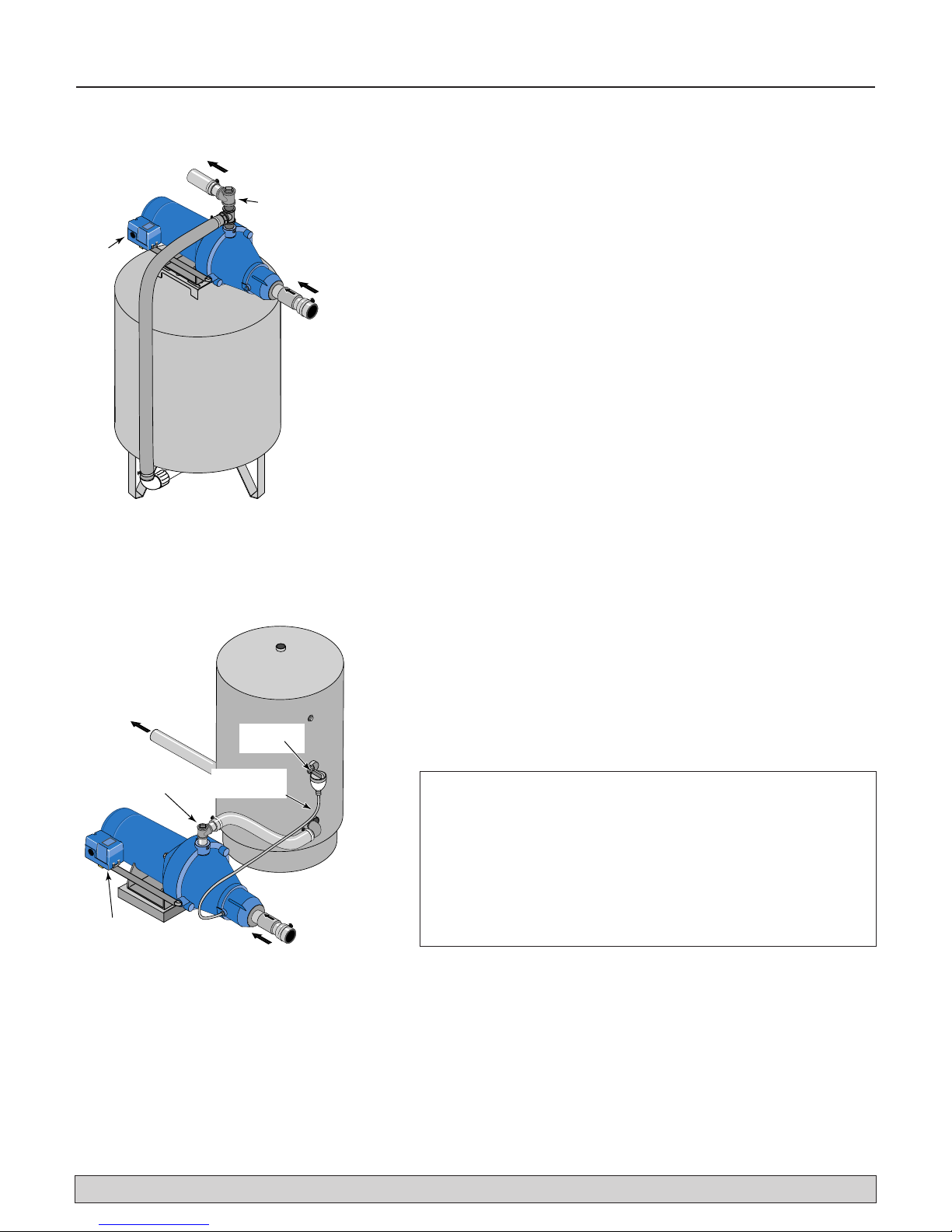
Discharge Pipe and Pressure Tank Connections 6
PRE-CHARGE TANK CONNECTION (Figure 4)
Step 1. Install two tees in the pump discharge port (see Figure 4). The pipe
size must be at least as large as the discharge port.
Step 2. Run a pipe or reinforced hose from one arm of the first tee to the
port on the pre-charged tank.
Step 3. Connect the other end of the discharge tee to your plumbing system.
Cap the tee with a threaded plug or a pressure gauge.
Step 4. Check the pre-charge of air in the tank with an ordinary tire gauge.
The pre-charge should be 2 PSI less than the cut-in setting of the
pump’s pressure switch. The pre-charge is measured
when there is
no water pressure in the tank.
Your new pump has a 30/50 PSI
switch, so adjust the tank pre-charge pressure to 28 PSI.
Congratulations! You have just completed the tank connection for
your jet pump.
Please go to Pages 7 and 8 for electrical hookup.
STANDARD TANK CONNECTION (Figure 5)
Step 1. Install one tee in the pump discharge port (see Figure 5).
Step 2. Run a pipe from the pump discharge port to the inlet port of your
tank. The pipe size must be at least as large as the discharge port.
Step 3. Remove the 1/8" NPT pipe plug from the pump Air Volume Control
(AVC) port (see Figure 5). Run tubing from the pump’s AVC port
(see Figure 5) to the port on the AVC mounted on the tank. See
instructions provided with tank and AVC for details. AVC port location will vary, depending on your pump model (see exploded
views, Page 10).
Congratulations! You have just completed the tank connection for
your jet pump.
Please go to Pages 7 and 8 for electrical hookup.
For parts or assistance, call Flotec Customer Service at 1-800-365-6832
S
Figure 4: Pre-charged Tank Connections
Figure 5: Standard Tank Connections
Sealing Pipe Joints
Use only Teflon tape or Teflon based joint compounds for
making all threaded connections to the pump itself. Do not use
pipe joint compounds on plastic pumps: they can react with
the plastic in pump components. Make sure that all pipe joints
in the suction pipe are air tight as well as water tight.
If the
suction pipe can suck air, the pump will not be able to pull
water from the well.
To Household
Water System
Pump Priming
Tee with Plug
or Gauge
Pressure
witch
1864 0795
From Well
To Household
Water System
Air Volume
Control
Pump Priming Tee
with Plug or Gauge
Pressure
Switch
Air Volume
Control Tube
From
Well
1865 0795
Electrical 7
For parts or assistance, call Flotec Customer Service at 1-800-365-6832
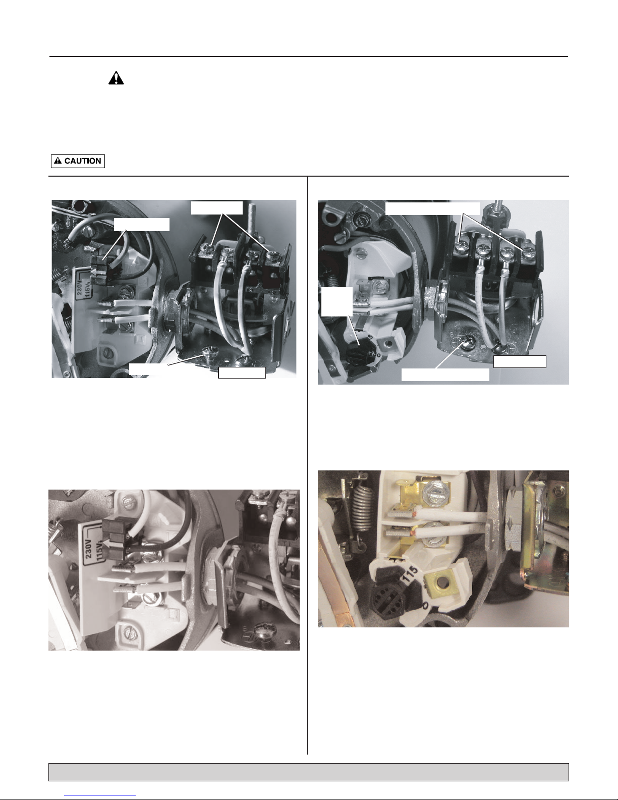
Disconnect power before working on pump, motor, pressure switch, or wiring.
Plug Type Voltage Selector
Voltage is factory set to 230 volts. To change to 115 volts:
1. Make sure power is off.
2. Pull the voltage change plug off of the tabs.
3. Move the voltage change plug to the 115 volt position. The plug will now cover 2 metal tabs and the
arrow on the plug will line up with the 115V arrow on
the label (see Figure 7).
4. Attach the incoming power leads to the two outer
screws on the pressure switch as shown in Figure 6.
5. Attach the ground wire to one of the grounding
connections, shown in Figure 6.
6. If there are other wires, they should be capped.
7. Reinstall the Motor end cover.
Dial Type Voltage Selector
Voltage is factory set to 230 volts. To change to 115 volts:
1. Make sure power is off.
2. Turn the dial counter-clockwise until 115 shows in the
dial window as shown in Figure 9.
3. Attach the incoming power leads to the two outer
screws on the pressure switch as shown in Figure 8.
4. Attach the ground wire to the grounding connections
as shown in Figure 8.
5. If there are other wires, they should be capped.
6. Reinstall the Motor end cover.
NOTE: 1/2 HP motors are wired for 115 volts only, and have no motor wiring to change.
3/4 HP or 1 HP motor terminal boards (located under the motor end cover) should look like one of those below.
If the motor can operate at either 115 or 230 volts, it is set at the factory to 230 volts. Do not change motor wiring
if line voltage is 230 volts, or if you have a single voltage motor.
Never wire a 115 volt motor to a 230 volt line.
MOTOR SWITCH SETTINGS
Figure 6:Voltage set to 230 volts, Plug Type
Figure 7:Voltage set to 115 volts, Plug Type
Figure 8:Voltage set to 230 volts, Dial Type
Figure 9:Voltage set to 115 volts, Dial Type
Power Connections
Voltage Change Plug
Ground Wire Connection
Pressure Switch
Power Supply Connections
Voltage
Change
Dial
Pressure Switch
Ground Wire Connection

Electrical 8
Hazardous voltage. Can shock, burn, or kill. Connect ground wire
before connecting power supply wires. Use the wire size (including the ground
wire) specified in the wiring chart. If possible, connect the pump to a separate
branch circuit with no other appliances on it.
Explosion hazard. Do not ground to a gas supply line.
WIRING CONNECTIONS
Fire hazard. Incorrect voltage can cause a fire or seriously dam-
age the motor and voids the warranty. The supply voltage must be within
±10% of the motor nameplate voltage.
NOTICE: Dual-voltage motors are factory wired for 230 volts. If necessary,
reconnect the motor for 115 volts, as shown. Do not alter the wiring in single voltage motors.
Install, ground, wire, and maintain your pump in compliance with the
National Electrical Code (NEC) or the Canadian Electrical Code (CEC), as
applicable, and with all local codes and ordinances that apply. Consult
your local building inspector for code information.
Connection Procedure:
Step 1. Connect the ground wire first as shown in Figure 6. The ground
wire must be a solid copper wire at least as large as the power
supply wires.
Step 2. There must be a solid metal connection between the pressure
switch and the motor for motor grounding protection. If the pressure switch is not connected to the motor, connect the green
ground screw in the switch to the green ground screw under the
motor end cover. Use a solid copper wire at least as large as the
power supply wires.
Step 3. Connect the ground wire to a grounded lead in a service panel, to a
metal underground water pipe, to a metal well casing at least ten
feet (3M) long, or to a ground electrode provided by the power
company or the hydro authority.
Step 4. Connect the power supply wires to the pressure switch as shown in
Figure 6.
You have just completed the wiring for your pump.
Please go to Page 9 for startup preparations.
For parts or assistance, call Flotec Customer Service at 1-800-365-6832
DISTANCE IN FEET(METERS) FROM MOTOR TO SUPPLY
0 - 100 101 - 200 201 - 300 301 - 400 401 - 500
Max. Load Branch Fuse
(0 - 30) (31 - 61) (62 - 91) (92 - 122) (123 - 152)
Motor HP Volts Amp Rating Amp AWG WIRE SIZE (mm2)
1/2 115 9.4 15 14 (2) 10 (5.5) 10 (5.5) 6 (14) 6 (14)
3/4 115/230 12.2/6.1 20/15 12/14 (3/2) 10/14 (5.5/2) 8/14 (8.4/2) 6/12 (14/3) 6/12 (14/3)
3/4 (4822) 115/230 14.8/7.4 20/15 12/14 (3/2) 8/14 (8.4/2) 6/14 (14/2) 6/12 (4/3) 4/10 (21/5.5)
1 (4832) 115/230 19.2/9.6 25/15 10/14 (5.5/2) 8/14 (8.4/2) 6/12 (14/3) 4/10 (21/5.5) 4/10 (21/5.5)
Wiring Chart – Recommended Wire and Fuse Sizes
Preparing to Start the Pump 9
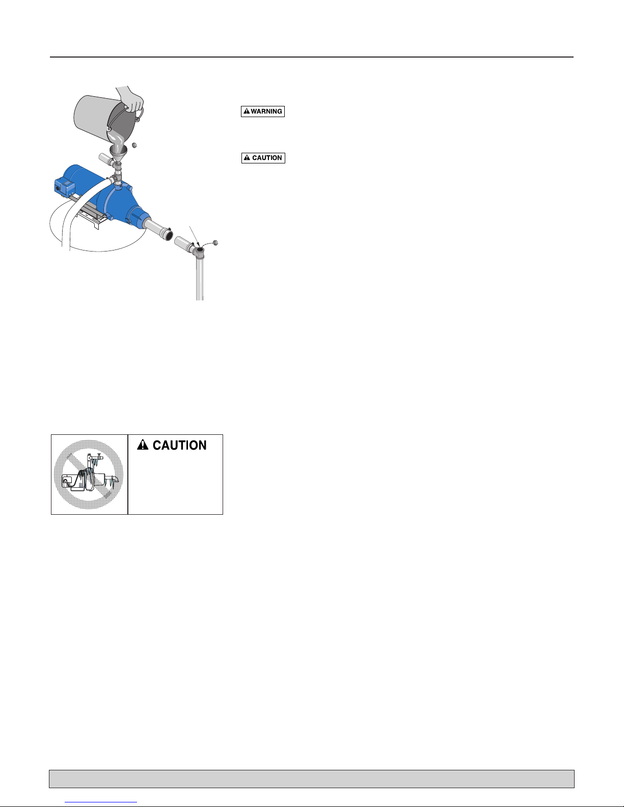
PRIMING
Never run pump against closed discharge. To do so can boil
water inside pump, causing hazardous pressure in unit, risk of explosion
and possibly scalding persons handling pump.
Never run pump dry. Running pump without water may cause
pump to overheat, damaging seal and possibly causing burns to persons
handling pump. Fill pump with water before starting.
Step 1. Remove the priming plug or gauge from the pump and fill the
pump, fill all piping between the pump and the well, and make
sure that all piping in the well is full. If you have also installed a
priming tee in the suction piping, remove the plug from the tee and
fill the suction piping.
Step 2. Replace all fill plugs.
Step 3. Power on! Start the pump. If you don’t have water after 2 or 3 min-
utes, stop the pump and remove the fill plugs. Refill the pump and
piping. You may have to repeat this several times in order to get all
the trapped air out of the piping. A pump lifting water 25’ may take
as long as 15 minutes to prime.
Step 4. After the pump has built up pressure in the system and shut off,
check the pressure switch operation by opening a faucet or two and
running enough water out to bleed off pressure until the pump
starts. The pump should start when pressure drops to 30 PSI and
stop when pressure reaches 50 PSI. Run the pump through one or
two complete cycles to verify correct operation. This will also help
clean the system of dirt and scale dislodged during installation.
WINTERIZING THE PUMP
To prepare the pump for freezing temperatures:
Step 1. Shut off power to the pump.
Step 2. Relieve system pressure. Open a faucet and let it drain until water
stops flowing.
Step 3. Drain the pump. Your pump may have a separate drain plug.
Remove this plug and let it drain.
Your pump may only have a plug or connection on the side of the
pump. Remove this and let the pump drain. Some water will
remain in the pump. A small amount of water left in the pump will
not harm it if it freezes.
Congratulations on a successful installation.
If you were unsuccessful, please refer to the Troubleshooting section
(Page 13) or call our customer service technical staff.
Thank you for purchasing Flotec Products.
For parts or assistance, call Flotec Customer Service at 1-800-365-6832
Figure 7: Prime the Pump
Fill pump
and piping
through
priming tee.
Can fill downpipe
separately through
priming tee.
Pump and piping will be
damaged if frozen and
not drained.
Follow winterizing
instructions.
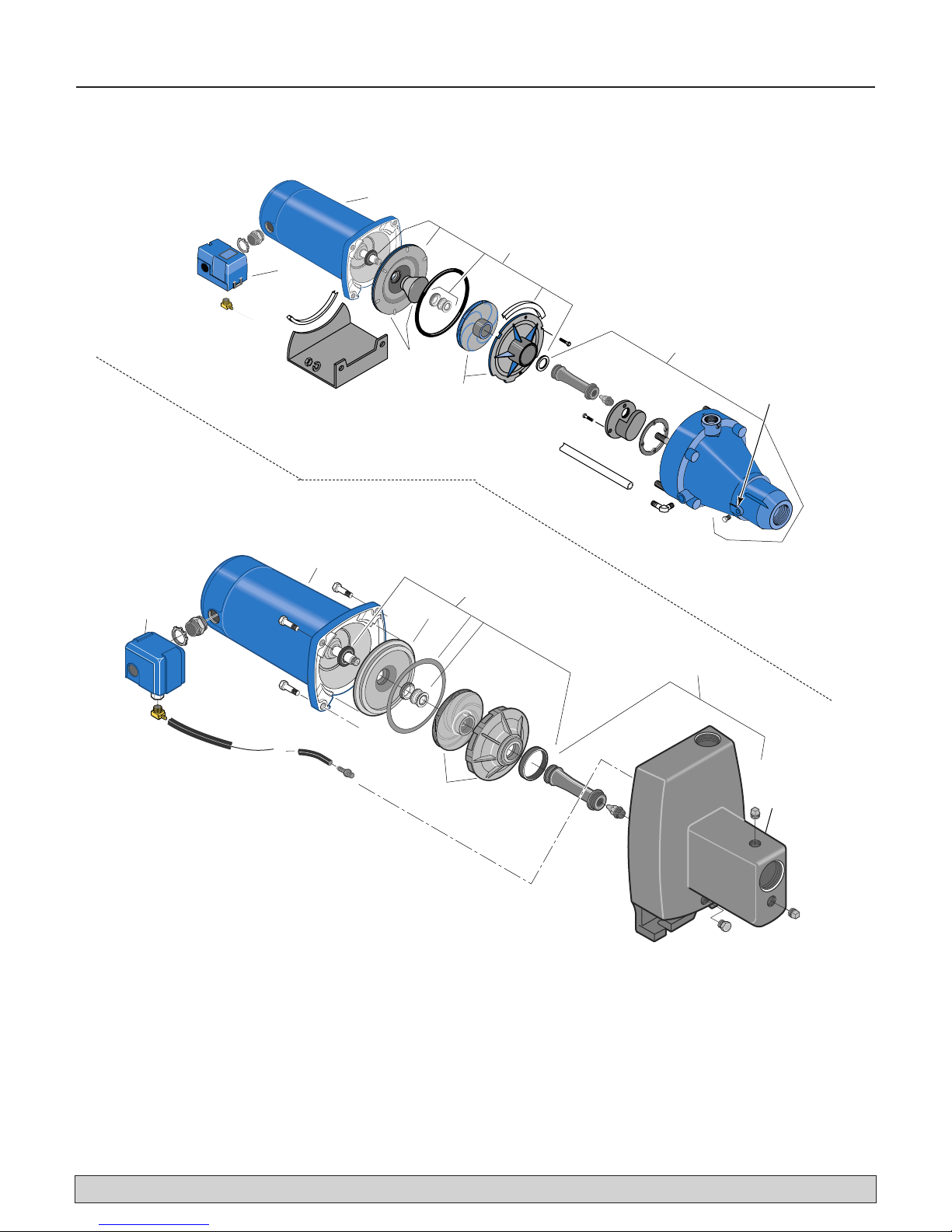
Repair Parts 10
For parts or assistance, call Flotec Customer Service at 1-800-365-6832
2490 0696
1
2
3
5 (Includes
Key No. 3)
6
4
AVC
Port
2
1
6
3
4
5 (Includes
Key No. 3)
1867 0795
AVC
Port
FP4012-08, FP4012-08C
FP4022-08, FP4022-08C
FP4112-08, FP4112-08C
FP4122-08, FP4122-08C

Repair Parts 11
For parts or assistance, call Flotec Customer Service at 1-800-365-6832
* Series FP4000 includes: Seal plate, O-Ring, and seal plate insert.
** Includes: Water slinger, seal plate O-Ring or gasket, shaft seal,
and diffuser O-Ring or gasket. Series FP4000 includes diffuser
pad also.
*** Included in model FP401215H-04 or FP401215H-04C (as
applicable).
§ Includes: Pump body, nozzle, and venturi. Series FP4000
includes venturi O-Ring; does not include check valve.
§§
Includes: Seal and Gasket Kit (Key No. 3), impeller, and diffuser.
Series FP4000 includes seal plate insert also.
Cast Iron Model Corrosion Resistant Model
and HP and HP
FP4112-08 FP4122-08 FP4012-08*** FP4022-08
Key Part FP4112-08C FP4122-08C FP4012-08C*** FP4022-08C
No. Description 1/2HP 3/4HP 1/2HP 3/4HP
1 Motor J218-577PKG J218-590PKG J218-577PKG J218-590PKG
2 Seal Plate Assembly* N3-9 N3-9 N203-12P N203-12P
3 Seal and Gasket Kit** FPP1550 FPP1550 FPP1530 FPP1530
4 Pump Body Assembly§ N176-38 N176-38F N176-35P N176-35PA
5 Overhaul Kit§§ FPP1560 FPP1561 FPP1520 FPP1521
6 Pressure Switch U217-1202 U217-1202 U217-1202 U217-1202
Models FP4112-08, FP4112-08C, FP4122-08, FP4122-08C,
FP4012-08, FP4012-08C, FP4022-08, and FP4022-08C
 Loading...