

Flotec FP400C Installation Instructions Manual
Sewage Pump System
MODEL FP400C
INSTALLATION INSTRUCTIONS
PRINTED IN U.S.A. FP538 (Rev. 8/12/04)
READ AND FOLLOW
SAFETY INSTRUCTIONS!
This is the safety alert symbol. When you see this sym-
bol on your pump or in this manual, look for one of the
following signal words and be alert to the potential for personal injury.
warns about hazards that will cause serious
personal injury, death or major property damage if ignored.
warns about hazards that can cause serious
personal injury, death or major property damage if ignored.
warns about hazards that will or can cause
minor personal injury or property damage if ignored.
The label NOTICE indicates special instructions which are
important but not related to hazards.
Carefully read and follow all safety instructions in this
manual.
Check your local codes before installing. You must comply
with their rules.
Vent sewage or septic tank according to local codes.
Do not install the basin or pump in any location classified as
hazardous by the United States National Electrical Code (NEC),
or by the Canadian Electrical Code (CEC), where applicable.
DESCRIPTION
FLOTEC Sewage Pump System, Model Number FP400C, is
ideal for basement installations, pumping below-grade toilets,
and laundry facilities. It includes a lightweight, corrosion resistant sump/sewage basin, FPW73-15 and cover, FPW73-17P.
These basins are used for residential, commercial, and industrial collection of sewage, effluent drainage and seepage
water. The basin cover kit includes an inlet hub, a gas tight
cover, vent and discharge grommets, cord seals, gaskets, and
hardware. Access openings allow for easy removal of the
pump without disturbing the vent connection. No special tools
or sealants are required.
NOTICE: This unit is not designed for applications involving salt
water or brine! Use with salt water or brine will void warranty.
INSTALLATION
Explosion hazard. Improper ventilation of
sewer gases can result in leakage of methane sewer gas, and a
possible explosion of fumes, resulting in severe injury or
death. Vent basin according to all local codes.
NOTICE: Proper ventilation is needed to prevent negative
basin pressure and to provide air for proper aerobic activity
within the basin.
The sewage basin should be located at the lowest place in the
basement or area to be drained. Floor drains from other areas
in the basement may be tiled into the basin. Drain tile around a
house foundation may also be tiled into the basin, effectively
removing water and relieving pressure from this area.
Basin covers are used to exclude refuse from the basin.
NOTICE: Read and understand this instruction manual before
your concrete floor is poured.
Installation Instructions
1. Dig the hole for the sewage basin and the sub-base. The
hole must be deep enough so the finished floor is flush
with the top of the basin. Refer to Figure 1, below.
NOTICE: The sub-base should include 4” of sand or
gravel. The maximum diameter of crushed rock should be
1/2”. The recommended maximum diameter of pea gravel
is 3/4”.
2. Level the sub-base out, until it is smooth. Sharp rock can
damage the basin.
3. Install the basin on top of the sub-base.
4. Backfill around the basin with crushed rock, with a maximum diameter of 1/2”, or use pea gravel.
5. Insert the 4” inlet pipe through the rubber grommet. Insert
it 2 inches into the basin. Dish soap can be used to lubricate the rubber grommet. If necessary, file the sharp
edges of the pipe to prevent damage to the grommet.
NOTICE: The pipe should pitch down to the basin inlet at
1/4” per foot. This will cause the water to run into the
basin.
6. Attach the discharge pipe to the sewage pump. The discharge pipe should stick up and out of the basin 6-10”.
7. Drill a 3/16” hole in the discharge pipe 3” above the
pumps discharge pipe thread.
®
P.O. Box 342, Delavan, WI 53115
Phone: 1-800-365-6832 • Fax: 1-800-526-3757
E-Mail: info@flotecwater.com • Web Site: http://www.flotecpump.com
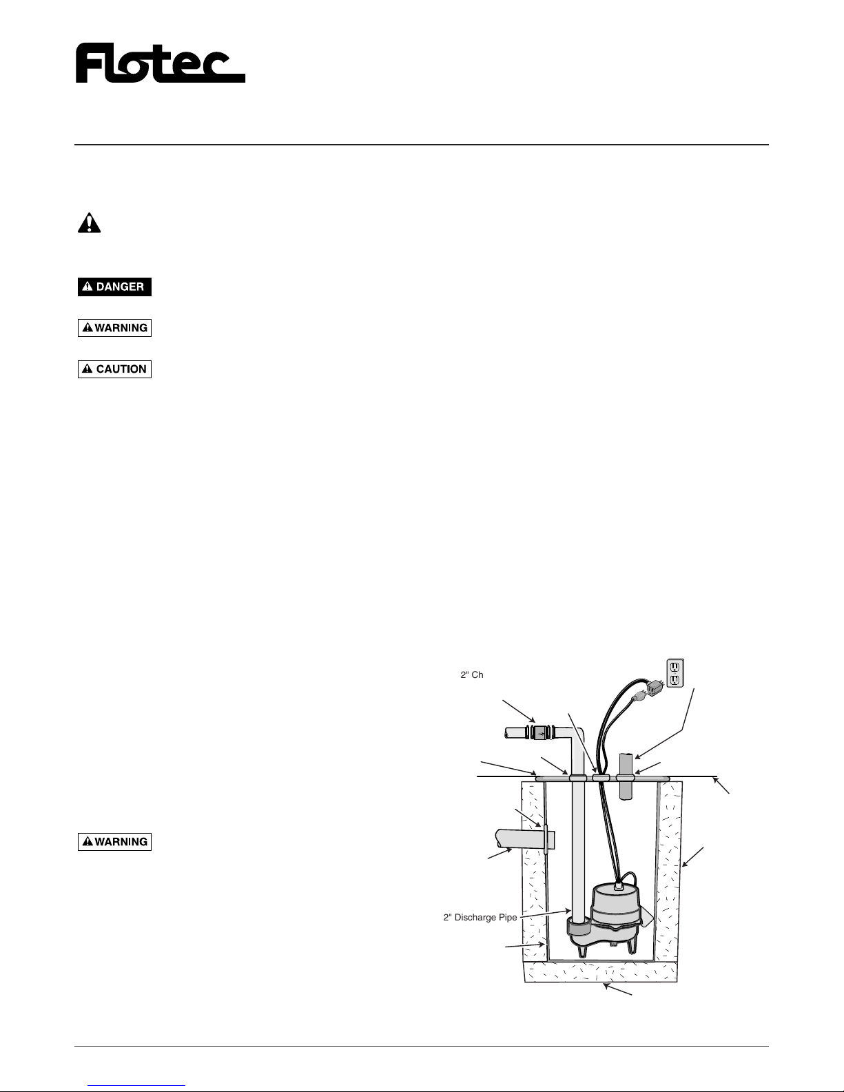
Figure 1 – Typical Installation
Plug into a Properly
Grounded Outlet
2" Checkvalve
Do Not Mount
Ver tically
Discharge
Poly Basin
Cover
Inlet Hub/Grommet
Grommet
Electric Cord
Grommet
FLOW
2" Vent Pipe.
Extend through
roof of building
or connect to
existing
vent pipe.
2" Vent Pipe
Grommet
Finished
Floor
4" Inlet Pipe
Slope @ 1/4"
Per Foot
2" Discharge Pipe
Poly Basin
4" Backfill
Requirement
4" Compacted Sub-base
Requirement
3620 1199 INST.
2
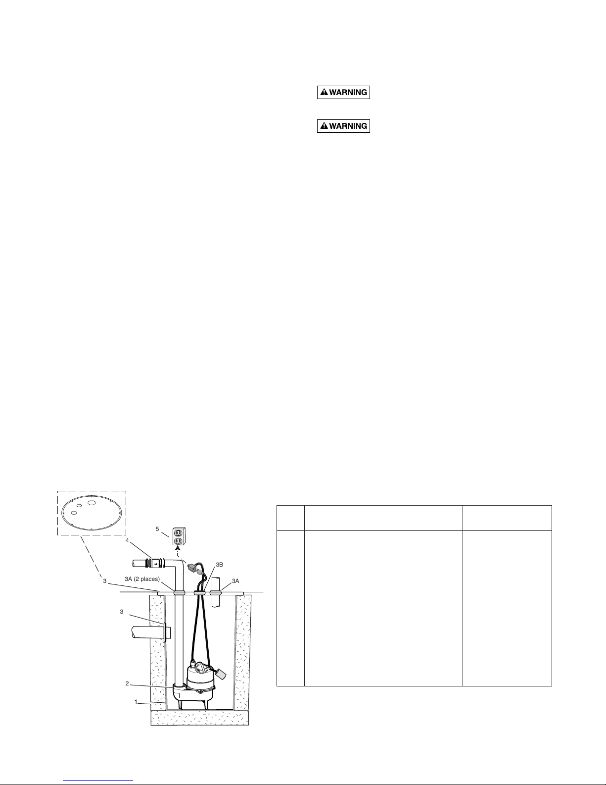
Key Part
No. Description Qty. FP400C
1 Sewage Basin 1 FPW73-15
2 Sewage Pump 1 FPSE3200A
3 Sewage Basin Cover (Includes
Fittings Package PW73-43) 1 FPW73-17P
3A 2” Grommet, (Discharge and
Vent Grommets) 2 *
3B Cord Grommet 1 *
3C Foam Gasket Seal
w/Adhesive Backing (#) 6 Ft. *
3D Bolts, 1/4-20 x 1” (#) 4 *
3E Washers, 5/16” (#) 4 *
3F 4” Inlet Hub 1 –
4 Check Valve, 2” Swing PVC 1 FPW212-4
5 Properly Grounded Outlet – (†)
REPAIR PARTS
8. Set the pump and pipe down into the basin.
9. Install the rubber discharge grommet into the basin cover.
Lubricate the grommet with dish soap and slide the cover
down over the discharge pipe. If necessary, file the sharp
edges of the pipe.
10. Pull the power cords up, through the center electric cord
hole and Install the electric cord grommet, into the cover.
11. Install the rubber vent pipe grommet into the vent hole, in
the cover. Slide the 2” vent pipe 2 inches into the hole.
The vent pipe must go through the roof of the building or
it can be connected to an existing vent pipe. The sewage
basin must be vented.
NOTICE: Bolt the lid to the basin. Do this before the concrete floor is poured. This will prevent wet concrete from
filling up your bolt holes and keep the basin from warping.
12. Install a 2” check valve in the horizontal portion of the
discharge pipe. See Figure 1. Make certain, the flow indicating arrow, points away from the pump. This check
valve will keep the water from running back into the
basin when the pump is not running.
13. Double check the connection between the discharge pipe
and the septic or sewage tank. They must be connected
before the pump is plugged in.
14. Insert the float switch piggy-back plug into the properly
grounded outlet.
15. Plug the pump into the piggy-back plug.
16. Check the operation by filling the sump basin with water
and observing pump operation through one complete
cycle.
Failure to make this operational check may
lead to improper operation, premature failure, and flooding.
Explosion hazard. Improper ventilation of
sewer gases can result in leakage of methane sewer gas, and a
possible explosion of fumes, resulting in severe injury or
death. Vent basin according to all local codes.
NOTICE: Proper ventilation is also needed to prevent negative
basin pressure and to provide the necessary air for proper aerobic activity within the basin.
MAINTENANCE
The sump basin and cover, pump, and piping should be protected from freezing temperatures. If there is any danger of
freezing temperatures, the unit should be drained. Consult
your pump manual for instructions on how to drain the pump
to protect it from freezing.
NOTE: No replacement parts available. Do not install basin or
pump in any location classified as hazardous by the United
States National Electrical Code (NEC), or by the Canadian
Electrical Code (CEC), where applicable.
(#) Not Illustrated.
(*) Included in Fittings Package, Part Number PW73-43.
(†) Not available.
5
4
FLOW
3A (2 places)
3
3F
2
1
3B
3A
3
Système de pompage
MODÈLE FP400C
des eaux usées INSTRUCTIONS D’INSTALLATION
LIRE TOUTES CES
INSTRUCTIONS ET LES SUIVRE!
Ce symbole indique qu’il faut être prudent. Lorsque ce
symbole apparaît sur le système ou dans cette Notice,
rechercher une des mises en garde qui suivent, car elles
indiquent un potentiel possible de blessures corporelles.
avertit d’un danger qui causera des blessures
corporelles, la mort ou des dommages matériels importants si on
l’ignore.
avertit d’un danger qui risque de causer des
blessures corporelles, la mort ou des dommages matériels importants si on l’ignore.
avertit d’un danger qui causera ou qui risquera de
causer des blessures corporelles, la mort ou des dommages
matériels importants si on l’ignore.
Le mot NOTA indique des instructions spéciales et importantes
n’ayant aucun rapport avec les dangers.
Lire attentivement toutes les consignes de sécurité contenues
dans cette Notice.
Avant de procéder à l’installation, consulter les codes de la
municipalité et s’y conformer.
Mettre à l’air libre la fosse des eaux d’égout ou la fosse septique,
conformément aux codes de la municipalité.
Ne pas installer le bassin ni la pompe dans un endroit classé
comme étant dangereux par le United States National Electrical
Code (NEC) ou le Code canadien de l’électricité.
DESCRIPTION
Le système de pompage des eaux usées FLOTEC, numéro de
modèle FP400C, est idéal pour être installé dans les sous-sol,
pour le pompage des toilettes installées au-dessous du niveau du
sol et pour les laveries, buanderies et blanchisseries. Ce modèle
est livré avec un bassin des eaux usées/de puisard léger et résistant à la corrosion, FPW73-15 et avec un couvercle, FPW73-17P.
Ce bassin est utilisé dans les résidences, les commerces et les
industries pour recueillir les eaux usées, les effluents et les eaux
d’infiltration. Le couvercle du bassin comprend un raccord
d’arrivée, un couvercle étanche aux gaz, des bagues de passage
pour les tuyaux de mise à l’air libre et de refoulement, des joints
d’étanchéité et toutes les fixations. L’ouverture d’accès permet
une dépose facile de la pompe sans avoir à déranger le branchement du tuyau de mise à l’air libre. Aucun outil spécial ni produit
d’étanchéité ne sont requis.
NOTA : Cette pompe n’est pas conçue pour pomper de l’eau
salée ni de la saumure! La garantie sera annulée si cette pompe
est utilisée pour pomper de l’eau salée ou de la saumure.
INSTALLATION
Danger d’explosion. Une ventilation
inadéquate des gaz des eaux usées peut causer une fuite de gaz
méthane et l’explosion possible des vapeurs, ce qui risquerait de
causer de graves blessures, voire la mort. Le bassin doit être mis à
l’air libre conformément à tous les codes de la municipalité.
NOTA : Une ventilation adéquate est indispensable pour
empêcher qu’une pression négative ne se forme dans le bassin et
pour un apport d’air nécessaire à l’activité aérobie dans le bassin.
Le bassin doit être placé à l’endroit le plus bas du sous-sol ou dans
la partie à drainer. Les drains de plancher des autres parties du soussol peuvent être branchés sur le bassin. Les tuyaux de drainage
posés autour des fondations de l’habitation peuvent également être
branchés dans le bassin, ce qui permettra d’éliminer efficacement
l’eau et de dissiper la pression de cette partie de l’habitation.
Le couvercle empêche les débris de tomber dans le bassin.
NOTA : Avant de couler le béton du plancher, lire et bien comprendre les instructions figurant dans cette notice.
Instructions d’installation
1. Creuser le trou nécessaire pour la pose du bassin des eaux
usées et la couche portante sur laquelle il reposera. Le trou
doit être suffisamment profond de façon que le haut du bassin
affleure la partie supérieure du plancher lorsqu’il sera collé.
Se reporter à la Figure 1 ci-dessous.
NOTA : La couche portante sur laquelle le bassin reposera
doit se composer de 4 pouces de sable ou de gravillon. Le
diamètre maximum de la roche concassée doit être de 1/2
pouce. Le diamètre maximum du gravillon ne pas dépasser
3/4 de pouce.
2. Étaler la couche portante sur laquelle le bassin reposera
jusqu’à ce qu’elle soit bien lisse. Les roches à arêtes vives
risquent d’endommager le bassin.
3. Poser le bassin sur la couche portante.
4. Remblayer autour du bassin avec de la roche concassée dont
le diamètre maximum ne dépassera pas 1/2 pouce ou avec du
gravillon.
5. Introduire le tuyau d’arrivée de 4 pouces dans la bague en
caoutchouc. Le faire dépasser de 2 pouces dans le bassin. Du
savon à vaisselle peut être utilisé pour lubrifier la bague en
caoutchouc. Au besoin, limer les arêtes vives du tuyau pour
qu’elles n’endommagent pas la bague.
NOTA : Le tuyau doit être incliné vers l’arrivée du bassin à
raison de 1/4 de pouce par pied afin que l’eau puisse couler
dans le bassin.
6. Brancher le tuyau de refoulement sur la pompe des eaux
usées. Le tuyau de refoulement doit dépasser verticalement du
bassin de 6 à 10 pouces.
7. Percer un trou de 3/16 de pouce dans le tuyau de refoulement, à 3 pouces au-dessus des filets du tuyau de refoulement
de la pompe.
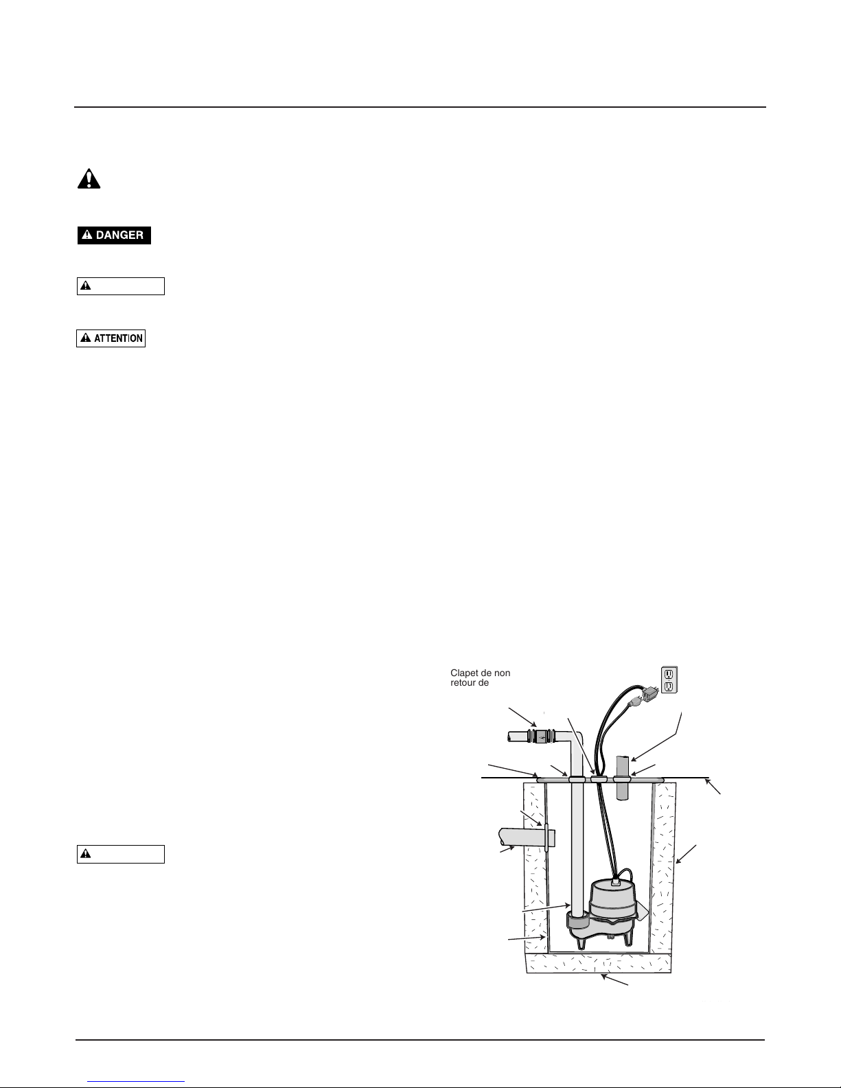
Figure 1 - Installation type
Clapet de non
retour de 2 po
Ne pas le monter
à la verticale
Bague du
cordon
électrique
Bague du tuyau de
mise à l’air libre de 2 po
Plancher
fini
Bague du tuyau
de refoulement
Couvercle
du bassin
en poly
Bague du raccord
de l’arrivée
Tuyau de mise à
l’air libre de 2 po. Il
doit dépasser le
toit du bâtiment ou
être branché sur
un tuyau de mise à
l’air libre existant.
Brancher le cordon électrique dans
une prise de courant mise à la terre
Tuyau d’arrivée
de 4 po incliné à
raison de 1/4 de
po par pied
4 po de
remblai
requis
Couche portante compactée
de 4 po requise
Tuyau de
refoulement
de 2 po
Bassin en poly
AVERTISSEMENT
Plug into a Properly
Grounded Outlet
2" Checkvalve
Do Not Mount
Ver tically
Poly Basin
Cover
Inlet Hub/Grommet
Discharge
Grommet
Electric Cord
Grommet
FLOW
2" Vent Pipe.
Extend through
roof of building
or connect to
existing
vent pipe.
2" Vent Pipe
Grommet
Finished
Floor
AVERTISSEMENT
4" Inlet Pipe
Slope @ 1/4"
Per Foot
2" Discharge Pipe
Poly Basin
4" Backfill
Requirement
4" Compacted Sub-base
Requirement
3620 1199 INST.
 Loading...