

Page 1
Direct Acting Pressure Reducing Valve Installation Instructions
Model C150E 1-½” & 2”
INSTALLATION INSTRUCTIONS:
Before installing reducing valve, flush out line to remove loose dirt and scale
which might damage seal ring and seat. Install valve in line with arrow on valve
body pointing in direction of flow. All valves will be furnished with factory
settings to reduce to 50psi. To readjust reduced pressure, loosen outer locknut
and turn adjustment screw clockwise (into cover) to raise reduced pressure, or
counterclockwise (out of cover) to lower reduced pressure. May be installed in
the horizontal or vertical position.
NOTICE: Annual inspection and maintenance is required of all plumbing
system components. To ensure proper performance and maximum life,
this product must be subject to regular inspection, testing and cleaning.
Regulators in series: Where the desired pressure reduction is more then
a 4 to 1 ratio (i.e.. 200psi to 50psi), multiple regulators in series should be
installed.
DIAPHRAGM WARNING: Loosen jamnut and adjustment screw slowly.
Look for any trapped water pressure under the diaphragm. Relieve
pressure before removing cover.
CAUTION: Anytime a reducing valve is adjusted, a pressure gauge must
be used downstream to verify correct pressure setting. Do not bottom out
adjustment screw on cover. Valve may be installed in any position.
HOW TO MAKE REPAIRS:
Shut Off Water Service Before Disassembly
1. Open a faucet on dwelling to relieve line pressure.
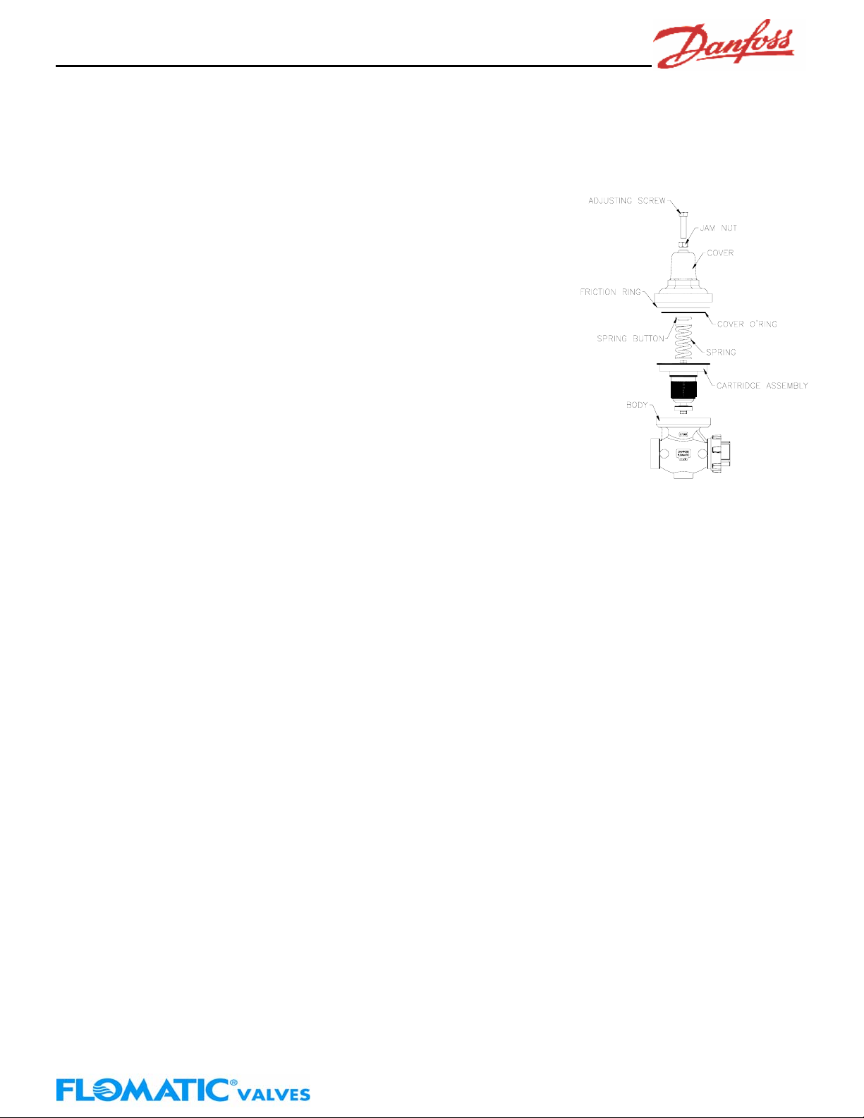
2. Note distance that adjustment screw protrudes from cover. Loosen jamnut on adjustment screw, then turn
adjustment screw out of cover to remove spring tension.
3. Unscrew cover counterclockwise and remove spring, spring button and friction ring.
4. Remove cartridge from regulator by gripping retaining bolt with pliers and pulling outwards away from body.
TO REASSEMBLE:
1. While disassembled, open inlet of water service to flush out valve body and service line of debris.
2. Replace old cartridge assembly with new cartridge assembly. Push the cartridge into bore in body making sure Orings seal tight against both the cartridge and body.
3. Replace friction ring, spring, spring button and cover. (make sure friction ring is installed with raised edge faced u p).
Tighten cover onto body by threading clockwise.
4. Turn adjustment screw into cover to old setting.
5. Enter dwelling and turn on several faucets.
6. Turn on water service. Let water run for several seconds then turn off faucets in dwelling.
7. Adjust regulator to desired pressure by turning adjustment screw clockwise (into cover) to raise pressure or
counterclockwise (out of cover) to lower pressure. NOTE: When reducing pressure, open a downstream faucet to
relieve pressure.
8. Tighten jamnut when desired pressure is achieved.
Limited One Year Warranty: Danfoss Flomatic valves are guaranteed against defects of m aterial or workmanship
when used for the services recommended. If, in any recommended service a defect develops due to material or
workmanship, and the device is returned, freight prepaid, to Danfoss Flomatic within 12 months from date of purchase, it
will be repaired or replaced free of charge. Danfoss Flomatics’ liability shall be limited to our agreement to repair or
replacement of valve only. Oil service requires special diaphragm and disc. Do Not use standard construction on oil
service.
Danfoss Flomatic Corp, 15 Pruyn’s Island, Glens Falls, New York 12801
Phone: 518-761-9797 Fax: 518-761-9798 www.flomatic.com
Danfoss Flomatic
C150003E
Rev. B
Page 2

Direct Acting Pressure Reducing Valve Installation Instructions
Model C150E 1-½” & 2”
General Trouble Shooting
Pipe lines in a water supply system must be of sufficient carrying capacity to maintain adequate pressure at the most
remote or highest fixture. Under the maximum probable fixture use, minimum adequate pressure is generally 8 to 15
lbs., but may be more, depending on the equipment being supplied.
Relatively high service pressures which can create high water velocities in pipe lines would allow use of smaller pipes
to satisfy fixture use. However, high velocities tend to cause whistling and humming. Reductions of pressure by the use
of a pressure reducing valve, in an attempt to eliminate the undesirable condition, may reduce pipe line capacities below
what is adequate for maximum probable use.
When high service pressures are in effect, either continuously or periodically, the application of a pressure re ducing
valve will be successful only when the installed pipe line is of adequate size to satisfy the system demand at the lower
pressure.
When actual water demands are unknown, the valve size should be no less than the existing pipe size.
PROBLEM
1. Pressure creeps or builds up in a system above
setting of pressure reducing valve.
A. Thermal expansion of water as it is being heated.
B. Foreign matter on seating face of sealing ring.
C. Cut, worn or chipped seal ring.
D. Cut or worn stem o-ring or worn o-ring groove.
SOLUTION:
A. This is a natural consequence. It may happen each time that the heater runs. A pressure relief valve or expansion tank
must be installed. It will not prevent pressure rise but should limit it to a safe level.
B. Flush the reducing valve by opening one or two fixture outlets wide. If this does not correct trouble, remove seal ring for
cleaning.
C. Replace with new seal ring. Temporary repairs may be made by turning seal ring over.
D. Replace with new stem o-ring and/or cartridge.
PROBLEM
2. Pressure and fixture flow unsteady.
A. Low water supply pressure in mains caused possible by
high area demands during certain periods of the day.
B. Heavy periodic demands by appliances in the house.
SOLUTION:
A. This is a water department problem. It is due to the mains being inadequate for the demands made on them.
B. House service lines may at times be inadequate for the load. Size of some pipelines may need to be increased. Pressure
setting of reducing valve may be too low.
C. Try increasing pressure before changing pipelines.
PROBLEM
3. Small inadequate flow from fixtures.
A. Pipelines to fixtures may be too small or house main
supply may be inadequate for normal fixture demand.
B. Heavy periodic demands by appliances in the house.
SOLUTION:
A. It may be necessary to increase pipe size only in some sections of the system leading to the offending appliances or
fixtures. Increasing the house service mains might be necessary if small supply is general at all fixtures .
B. Raise pressure gradually by readjusting valve until this point is determined.
C. Clean screen.
PROBLEM
4. Valve appears to be noisy, hums, whistles or
chatters.
A. Hum or whistle is usually caused by high velocity of flow in
pipelines causing vibration.
B. Chatter usually originates with worn seat washer or
loosely installed seat ring.
SOLUTION:
A. Pipelines could be small or too light. Reducing valves could be too small. Pipes and valves being small would accentuate
this condition.
B. Inspect seal ring. If a deep channel appears on seal ring face, replace or use the opposite side.
C. Frequently, noise appears in a faucet or appliance and seems to originate in the reducing valve. There is a general
tendency to use streamline piping of a relatively small size. Velocity is naturally high, and noise of the fast moving-water is not
unusual.
POSSIBLE CAUSE OR CAUSES
POSSIBLE CAUSE OR CAUSES
POSSIBLE CAUSE OR CAUSES
C. Screen clogged with debris.
POSSIBLE CAUSE OR CAUSES
Danfoss Flomatic
Danfoss Flomatic Corp, 15 Pruyn’s Island, Glens Falls, New York 12801
Phone: 518-761-9797 Fax: 518-761-9798 www.flomatic.com
C150003E
Rev. B
 Loading...