

Page 1
UNLEADED
BACKFLOW PREVENTERS
OPERATION & MAINTENANCE MANUAL
LEAD
High Quality Valves Built to Last...
Page 2

Table of Contents
Features and Operating Procedures.....1
Specification Sheet RPZE 1/2" - 2".....2
Installation Guidelines & Procedures.....3
Trouble Shooting Procedures & Guide.....4
Trouble Shooting Solutions.....5
General Service Procedures RPZE/DCVE.....6
Check Valve Service Procedures.....7
Relief Valve Service Procedures.....8
Pressure Vacuum Breaker Service Instructions.....9
Repair Kits for PVB.....10
Repair Kits for RPZE & DCVE.....11
How to Contact & Warranty.....12
Page 3
OPERATING AND MAINTENANCE PROCEDURES
Reduced Pressure Backflow Preventer
Flomatic has a consistent backflow design that
ranges from 1/2"-10", (15mm-250mm). The Flomatic
Model RPZE II design is a more compact/economical
model and is used when space is limited. The
Flomatic Model RPZE is available in size 3/4"-2",
(19mm-50mm) with a unleaded bronze body and
cover as standard. The 2 1/2"-10", (64mm-250mm)
are manufactured with epoxy coated ductile iron
for strength.
The Flomatic backflow preventer includes tightly
closing resilient seated shut-off valves on each end
of the body. The assembly has two independent and
internally loaded check valves with a pressure
differential relief valve between them.
The pressure drop across the first check valve is
approximately 6.0 PSID (41 kPa). The relief valve
consists of a hydraulically balanced diaphragm.
The high-pressure side of the first check valve is
connected to the top of the diaphragm through an
access hole in the body of the casting. The low-pressure
side is connected to the reduced pressure zone
keeping the relief valve closed during normal
operation. This is spring loaded to force the relief
valve open when the pressure drop across the first
check reduces to approximately 2.5 PSID (17 kPa).
NORMAL FLOW CONDITION
High Quality Valves Built to Last...
Flow Direction
LEGEND
Inlet Pressure
Outlet Pressure
Intermediate Zone Pressure
1
Page 4
SPECIFICATION SHEET RPZE (1/2"-2") (12mm-50mm)
Features
•Unleaded body, test cocks and ball valves
•Ultimate mechanical protection of potable water,
against hazards of cross connection contamination.
•Meets all specifications of
AWWA,ASSE and USC Foundation for Cross
Connection Control and Hydraulic Research.
•Non-Interchangeable check valve assembly
•Replaceable check valve and removable 316 stainless
steel relief valve seats
•Top entry single access cover
•Vertical test cocks
•Low Head loss
•Simple construction, fewer parts
Operation
The backflow preventer shall be a Reduced Pressure
Principle and shall include a tightly closing resilient
seated shut-off valve on each end of the body.
The assembly shall be fitted with four (4) properly
located resilient seated test cocks.
The assembly shall have two (2) independent and
internally loaded check valve with a pressure differential
relief valve located between the check valves.
The backflow preventer shall meet the requirements of
the following standards:USC’s FCCC& Hr Manual,
Sec. 10, ASSE 1013 and CSA B64.4. Australia &
New Zealand AS/NZS 2845-1
FLOMATIC SPECIFICATIONS
The Reduced Pressure Principle backflow preventer
shall protect against backflow by either backpressure
or backsiphonage from a cross-connection between
potable water systems and substances that are
considered to have health hazards.
It shall consist of two (2) mechanically independent,
spring loaded, center guided check valves. It shall also
have a hydraulically dependent differential pressure
relief valve, set in an integral cast unleaded bronze
body, with a single access cover. The assembly shall
have four (4) vertical test cocks and two shut off
valves which are quarter-turn, full-port, resilient
seated and ball type.
The seat of each check valve and the relief valve
shall be replaceable. The check valves shall be held
into place by stainless steel clips and the check
valve assemblies shall be non-interchangeable with
silicone discs.
The backflow preventer shall be suitable for supply
pressure up to 175 psi (1205kPa) and water temperatures from 33 to 180 F.
2
Page 5
INSTALLATION GUIDELINES & PROCEDURES
Proper installation of the assembly is essential to the correct function of the assembly.
The following instructions are important characteristics of a proper installation.
1. Before installing any of Flomatic's backflow
assemblies, flush the lines thoroughly to
remove all debris, chips and other foreign
objects. Failure to do so may make any of these
assemblies inoperable.
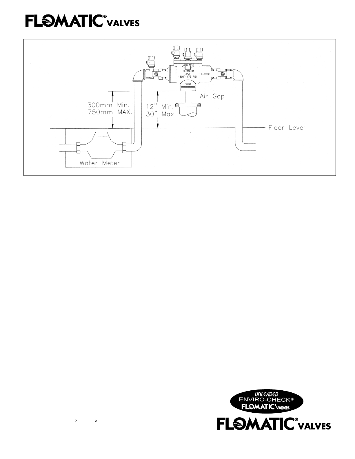
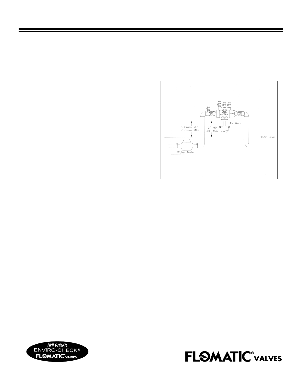
2. Allow sufficient clearance around the installed
assembly to conduct testing (minimum 18"
(450mm) around). The assembly should be
installed in a horizontal position with a minimal
clearance of 12" (300mm) between the relief
valve discharge port and the flood level. The
maximum height should be 30" (762mm) to
allow for testing at a reasonable height.
3. Flomatic's RPZE assemblies are approved by
national approval agencies and are to be installed
in a horizontal position. Approval agencies do
not recommend installation of a RPZE in a pit.
Flooding of the pit can result in a cross
connection contamination. If local codes permit
installation of a RPZE in a pit, adequate drainage
must be provided to prevent the pit from flooding.
4. Placement of the assembly should be planned
where water discharge from the relief valve will
not be objectionable or cause property damage.
5. Insure that the water supply pressure does not
exceed the manufacturer’s maximum water
pressure or temperature. The unit should also be
protected against thermal water expansion,
extreme backpressure and/or water hammer.
6. The most common cause of field problems
for RPZE’s is dirt or debris in the system.
At the time of installation dirt or debris will
become trapped in the first check seating area,
resulting in a continuous discharge from the
relief valve in a static or backflow condition.
THEREFORE THE SYSTEM SHOULD
ALWAYS BE FLUSHED BEFORE THE
ASSEMBLY IS INSTALLED.
7. To effectively flush the systems after the assembly
has been installed, remove the internal components
and open the inlet shutoff valve to flush all debris
from the line and assembly. If debris in the water
continues to cause problems, a strainer should be
installed upstream of the assembly.
3
Page 6

TROUBLE SHOOTING GUIDE
Reduced Pressure Backflow Preventers
With Differential Pressure Gauge
SYMPTOM NO. 1:
Check Differential Across No. 1 Check Valve
READING PROBLEM
2 to 3 PSID Leak in No. 1
14 to 21 kPa
6 to 8 PSID and steady Malfunctioning
41 to 55 kPa
2 to 7 PSID fluctuating Inlet pressure fluctuating
14 to 21 kPa
or No. 2 check valve
pressure relief valve
Without Differential Pressure Gauge
SYMPTOM NO. 1 and No. 2:
A.) Close Ball Valve No. 2
RESULT PROBLEM
If discharge stops Leak in No. 2
check valve
If discharge does not stop Go to
B) Open No. 4 testcock to produce a flow graeter
Than differential relief valve discharge
RESULT PROBLEM
"B"
Static Pressure Condition
800-833-2040 • 518-761-9797 • Fax 518-761-9798
www.flomatic.com
e-mail: [email protected]
If discharge stops Leak in No. 1
check valve
If discharge does not stop Malfunctioning
pressure relief valve
4
Page 7
TROUBLE SHOOTING GUIDE
Reduced Pressure Backflow Preventers
PROBLEM
1. Valve releases water
on and off from the
relief valve
2. Valve releases water
constantly from the
relief valve.
CAUSE SOLUTION
1a. Inlet pressure fluctuations
1b. Outlet pressure fluctuations
2a. Dirt or debris is on the first
check.
2b. Damaged or dirty relief valve
seat
2c. Relief valve piston "O" ring not
free to move to scale, dirt or buildup of mineral deposits.
1a. Install a soft seated, spring loaded
check valve on the inlet side of the
assembly. (Flomatic model 80E)
1b. Install a soft seated, spring-loaded
check valve on the outlet side of the
assembly as close as possible to the
shutoff valve. (Flomatic model 80E)
2a. Flush valve, If flushing does
not work then clean or replace the
first check.
2b. Clean or replace the relief
valve seat.
2c. Clean, grease or replace the
piston "O" ring.
3. Valve exhibits
high-pressure Drop
4. No water flows
downstream of valve
5. No water flows
downstream of valve
6. Valve quickly and
repeatedly fouls
following servicing.
2d. Excessive backpressure,freezing,
or water hammer has distorted the
second check.
2e. Valve improperly reassembled.
3a. Fouled strainer.
3b. Valve too small for flow.
4. Valve installed backwards
5a. Follow Flomatic’s test procedure.
5b. Leaky downstream gate valve.
6a. Debris in pipeline is to fine to
be trapped by strainer.
2d. Eliminate source of excessive
backpressure or water hammer in the
system downstream of the device.
Use Flomatic Model 80E to dampen
out backpressure. In case of freezing;
thaw, disassemble, and inspect internal
components. Replace as necessary.
2e. Install check springs in their
proper location
3a. Clean strainer or replace.
3b. Install proper size device based on
flow requirements
4a. Install valve in accordance with flow
direction arrow
5a, 5b. Clean or replace gate valve with
full port ball valves or resilient wedge
shutoff valves.
6a. Install a finer mesh strainer element
in the strainer.
5
Page 8
GENERAL SERVICE PROCEDURES RPZE/DCVE
Flomatic backflow preventers can be serviced in the field with common household tools. All assemblies have a
consistent design with all parts being located in the same locations and valves serviced in the same way.
1. First closed inlet and outlet shut-off valves and bleed any
pressure by opening the #4 testcock, then the #3 and #2.
2. Next use a wrench or socket to take the bolts out
of top cover. After taking the cover off carefully inspect
diaphragms, seals and seating surfaces for debris or damage.
(RPZE Fig. 1 DCVE Fig.1a)
Figure 1
Figure 1a
Figure 2a
5. Next use a medium straight blade screw driver to carefully
pry the check valve out.
6. After check valve is out of the body, check
for any build up of calcium or other mineral deposits. If this
condition exits, then carefully remove any build-up with a
straight blade screw driver. Also check the O-ring on the
check valve for any cuts if it is cut or has any deposits
remove and replace or clean.
7. When check valve is out of the body grasp check valve disc
holder and use a wrench or socket to unscrew the check
valve stem from the disc holder. (Figure 3).
Figure 3
3. After taking the cover off either check valve can be removed
by simply using pliers to grasp the spring clip (RPZE figure 2,
DCVE figure 2a).
4. Refer to parts list and figures for detailed parts.
Do not use any petroleum based oils, grease, solvent or pipe
dope on any of the parts unless instructed to do so. Use only
lubricants that comply with FDA PORTABLE WATER
requirements for use in drinkable water systems or lubricants supplied by the manufacturer.
Figure 2
6
8. When check valve is disassembled, inspect the check valve
seat for any cuts along the seat ring diameter. If seat is cut, it
is a sign of high back pressure from thermal water expansion,
water hammer or other causes of excessive water hammer. If
seat is cut or damaged, it should be replaced, or turn used
disc over if new seat disc is not available.
Page 9
SERVICE PROCEDURES FOR RPZE/DCVE CHECK VALVE
Necessary components
• Adjustable Wrench • Pliers • Flat head screw driver • Socket wrench set • Loctite 242 (blue)
Visually inspect the rubber discs, springs and bolts for defects
If check valve disc is damaged then call a service center or factory for a rubber kit. If the
check valve seat ring or spring is damaged call for a complete replacement check valve.
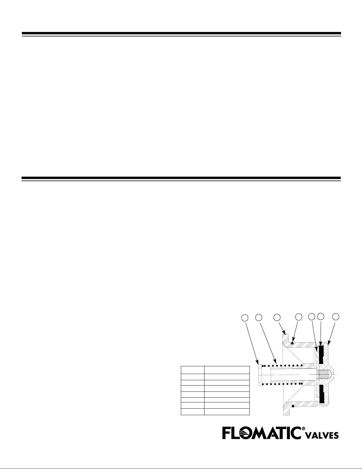
SUB-ASSEMBLIES: 1ST AND 2ND CHECK VALVES
1. Place check valve disc into check valve disc holder then place check valve disc retainer
washer (with shiny side down and dull side up) over the check valve disc.
2. Place the 1st or 2nd check valve seat ring on top of the disc retainer and place O-ring around
the slot in the seat ring. Then align these items with threaded hole in check valve disc holder.
3. Apply Loctite on the threads of the check valve disc holder.
4. Slide the spring down the shaft of the 1st or 2nd check valve seat ring. (Use heavy spring for 1st
check in RPZE units)
5. Thread the check valve stem through the assembly and tighten the stem into threads on the
check valve disc holder.
NOTE: RPZE and DCVE check valve assemblies are identical with the exception of the
1st check valve spring.
6
5
1
ITEM DESCRIPTION
1 C.V. STEM
2 C.V. SPRING
3 2nd C.V. SEAT RING
4 C.V. O-RING
5 C.V. DISC REAINER
6 C.V DISC
7 C.V. DISCHOLDER
2
3
4
7
7
Page 10
SERVICE PROCEDURES FOR RPZE RELIEF VALVE
Necessary components • Adjustable Wrench • Pliers • Flat head screw driver •
Socket wrench set-Loctite 242 (blue) Relief Valve Assembly
1. After removing the cover of the backflow preventer then remove the
relief valve assembly from body. Inspect the assembly for debris
or damage.
2. Grasp the bottom disc retainer and use a Allen wrench to take the
assembly apart. Turn the Allen wrench counter clockwise until the
assembly is apart. (figure 1)
Figure 1
3. If the relief valve disc/rubber has dirt or debris on it,
rinse in clean water. If the disc/rubber is cut or damage
beyond repair, contact service center or factory and request a
rubber kit for the relief valve assembly.
Figure 2
4. Put relief valve diaphragm plate down the stem then place relief
valve diaphragm on top of plate and screw piston onto stem.
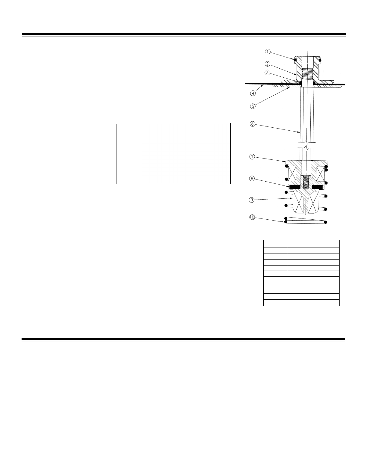
ITEM DESCRIPTION
5. Put the O-ring onto the relief valve piston.
6. Then place relief valve disc holder on the bottom of the
shaft and put the relief valve disc/rubber into disc holder,
then screw relief valve retainer on to threads.
1 PISTON O'RING
2 R.V. PISTON
3 R.V. STEM O-RING
4 R.V. DIAPHRAGM
5 R.V. DIAPHRAGM PLATE
6 R.V. STEM
7 R.V. DISCHOLDER
8 R.V. DISC
9 R.V. DISC RETAINER
10 R.V. SPRING
RELIEF VALVE ASS'Y
RPZE/DCVE BACKFLOW REASSEMBLY
Visually inspect the valve body, springs and bolts for defects. Carefully remove any debris or foreign material
with a flat head screwdriver.
Directions for assembly
1. Put lubricant on the 1st and 2nd check valve O-rings.
2. Put the 1st check valve into the body and secure with clamp.
3. Do the same for the 2nd check valve.
4. Lubricate relief valve O-ring with Silicone Lubricant.
5. For the RPZE UNITS Lubricate the relief valve seat into body and put spring over the seat then a-line relief
valve assembly with hole in seat and the holes in the diaphragm.
6. Place the RPZE/DCVE cover over the body and secure with bolts (on the RPZE units the 2 small slits on
the diaphragm should face the inlet side).
8
Page 11
GENERAL SERVICE INSTRUCTIONS
PRESSURE VACUUM BREAKER 3/4"-1" (20mm - 25mm)
1. Removal of bonnet/poppet
a. Close outlet ball valve then close inlet ball valve.
Bleed residual pressure by opening No. 2 testcock.
Figure 1
b. Remove canopy screws and canopy.
c. Unscrew bonnet assembly from valve body by hand
(If necessary, use appropriate size
wrench on the outside diameter of bonnet).
d. Remove poppet/seal for any cracks or debris if it
is dirty then clean with warm water.
2. Removal of check valve
a. After removing the bonnet/poppet inspect the check
valve.
b. Use a 12 point 1-3/8" socket to unscrew check valve
out from the body (see figure 2)
.
c. Clean and inspect all components thoroughly prior
to reassemble.
d. Vent and check valve discs are reversible.
e. Use flat head screw driver to disassemble the
check valve (see figure 3)
Figure 2
Figure 3
9
Page 12
PRESSURE VACUUM BREAKERS REPAIR SERVICE KITS
PVB Check Valve Assembly - For Models B9500 & B9501
Kit Model Number: 89598PO
Kit Parts Part Description Part Materials
9259200 Check Valve Disc Holder GFC BASF#GC25A
9759300 Check Valve Disc Silicone Rubber
9259400 Check Valve Seat Ring Noryl GFN2 - 780s
9782900 Check Valve Seat O’Ring Buna - N
9659600 Check Valve Spring 302 Stainless Steel
9359700 Check Valve Spring Retainer Bronze B140-83
8474 #8-32 x 1/2 RHSTCS 18-8 Stainless Steel
PVB Air Vent Assembly - For Models B9500 & B9501
Kit Model Number: 89599PO
Kit Parts Part Description Part Materials
925860 Vent Canopy ABS
9258700 Bonnet Noryl GFN2 - 780s
9758800 Bonnet O’Ring Buna - N
9658900 Vent Spring 302 Stainless Steel
9759000 Vent Disc Silicone Rubber
9259100 Vent Disc Holder Polythylene
8473 Screws, 6-32x3/8 18-8 Stainless Steel
PVB Check Valve Assembly - For Models B9500 & B9501
Kit Model Number: B95RKOO
Kit Parts Part Description Part Materials
9758800 Bonnet O’Ring Buna - N
9782900 Check Valve Seat O’Ring Buna - N
9759000 Vent Disc Silicone Rubber
9759300 Check Valve Disc Silicone Rubber
10
Page 13
23
3
LEAD
4
5
7
Relief Valve Assembly
15
17
16
10
st
1
Check Valve Assembly
11
12
13
14
21
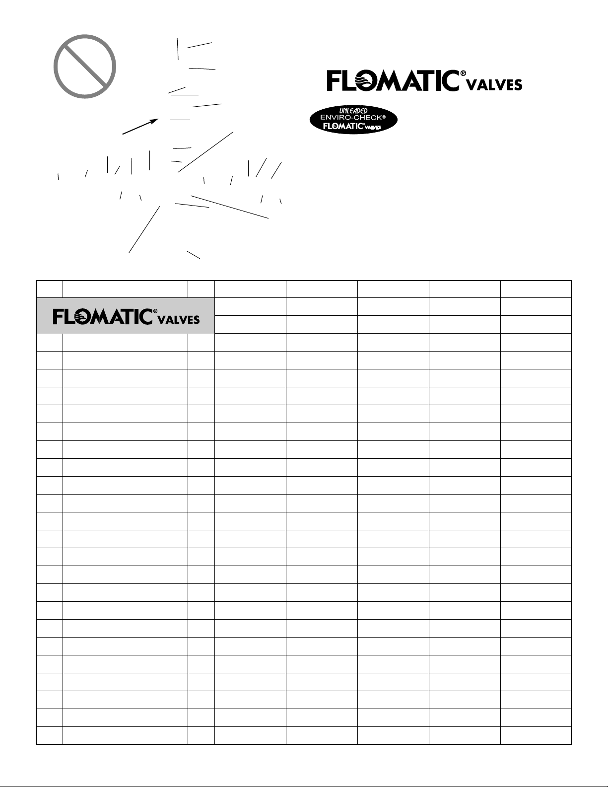
ITEM # QTYDESCRIPTION RPZE II
1
BODY
8
9
10
1
1
2
6
20
nd
2
Check Valve Assembly
12
19
22
1/2'' & 3/4''
B9399E / B9300E
8382E9, E20
14
18
15
16
17
B9200E / B9201E
BACKFLOW
PREVENTERS...
Better By Design
Air Gap Standard*
Silicone Discs
Top Entry Single Access Cover
Relief Valve Will Not Spray
Vertical Test Cocks
*Up to 2"
RPZE RPZE RPZE II RPZE
3/4'' & 1''
83820E0, 1E1
1-1/4''
B9202E
83820E2
1-1/2''
B9303E
83820E3
B9203E / B9204E
1-1/2'' & 2''
83810E3, OE4
2
3
4
5
6
RV DIAPHRAGM / DIAPHRAGM PLATE
7
8
9
10
11
12
13
14
15
16
17
18
RELIEF VALVE DISC RETAINER
1ST & 2ND CV DISC HOLDER
1ST & 2ND CV SPRING CLIP
COVER
TESTCOCK
RELIEF VALVE PISTON
RELIEF VALVE O-RING
RV STEM / STEM O-RING
RV DISC / DISC HOLDER
1ST & 2ND CV STEM
1ST CV SPRING
1ST & 2ND CV O-RING
1ST CV SEAT RING
1ST & 2ND CV WASHER
1ST & 2ND CV DISC
2ND CV SEAT RING
1
4
1
1
1
1
1
1
2
1
2
1
2
2
2
2
1
83822E9
9383395E
9283299
9783899
9783999
9283499
9783699
9283599
9382499
9682899
9872999
9282399
9682799
9782699
9382599
9684299
9283099
83822E0
9383395E
9283200
9783800
9783900
9283400
9783600
9283500
9382400
9682800
9782900
9282300
9603201
9782600
9382500
9684200
9283000
83822E2
9383397E
9283202
9783802
9783902 / 9686202
8383402 / 9785602
9783602 / 9286102
9283502
9382402
9682802
9782900
9282300
9603201
9782600
9382500
9684200
9283000
83822E3
9383397E
9283202
9783802
97839A3 / 9686202
83834A3 / 9785602
9783602 / 9286102
9283502
83824A3
96828A3
97829A3
92823A3
96032A3
97826A3
83825A3
96842A3
92830A3
83812E3
9383397E
9283203
9783803
9783903 / 9686203
8383403 / 9783803
9783603 / 9286103
9283503
8382403
9682803
9782903
9282303
9682703
9782603
83825E3
9684203
9283003
19
20
21
22
23
2ND CV SPRING
RV SPRING
RV SEAT
RV SEAT O-RING
COVER BOLTS
1
1
1
1
4
9683199
9683799
9684099
9784199
8296
9683100
9683700
9684000
9784100
8446
9683102
9683702
8684002
9784102
8446
96831A3
96837A3
8684002
9784102
8449 (USES 6)
9683103
9683703
8684003
9784103
8449 (USES 6)
11
Page 14
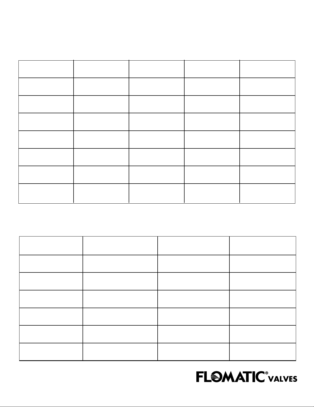
Repair Kits
Model RPZE & RPZE II
Size Relief
1/2" & 3/4"
RPZE II
(4, 5, 6, 7, 8, 9, 20, 21, 22)
3/4" & 1"
(4, 5, 6, 7, 8, 9, 20, 21, 22)
1 1/2" & 2"
2 1/2" & 3"
4"
6"
8"
(4, 5, 6, 7, 8, 9, 20, 21, 22)
(4, 5, 6, 7, 8, 9, 20, 21, 22)
(4, 5, 6, 7, 8, 9, 20, 21, 22)
(4, 5, 6, 7, 8, 9, 20, 21, 22)
(4, 5, 6, 7, 8, 9, 20, 21, 22)
Complete
89880P9
89850P0
89850P3
89850P5
89850P7
89850P9
89850P10
1st Check 2nd Check Rubber Kit
89878P9
(10, 11, 12, 13, 14, 15, 16, 17)
89848P0
(10, 11, 12, 13, 14, 15, 16, 17)
89848P3
(10, 11, 12, 13, 14, 15, 16, 17)
89848P5
(10, 11, 12, 13, 14, 15, 16, 17)
89848P7
(10, 11, 12, 13, 14, 15, 16, 17)
89848P9
(10, 11, 12, 13, 14, 15, 16, 17)
89848P10
(10, 11, 12, 13, 14, 15, 16, 17)
89879P9
(10, 12, 14, 15, 16, 17, 18, 19)
89849P0
(10, 12, 14, 15, 16, 17, 18, 19)
89849P3
(10, 12, 14, 15, 16, 17, 18, 19)
89849P5
(10, 12, 14, 15, 16, 17, 18, 19)
89879P7
(10, 12, 14, 15, 16, 17, 18, 19)
89879P9
(10, 12, 14, 15, 16, 17, 18, 19)
89879P10
(10, 12, 14, 15, 16, 17, 18, 19)
(5, 6, 8, 12, 15, 22)
(5, 6, 8, 12, 15, 22)
(5, 6, 8, 12, 15, 22)
(5, 6, 8, 12, 15, 22)
(5, 6, 8, 12, 15, 22)
(5, 6, 8, 12, 15, 22)
(5, 6, 8, 12, 15, 22)
B93RK99
B92RK00
B92RK03
B92RK05
B92RK07
B92RK09
B92RK10
Model DCVE
Size 1st Check 2nd Check Rubber Kit
3/4" & 1"
1 1/2" & 2"
2 1/2" & 3"
4"
6"
8"
89855P0
89855P3
89855P5
89855P7
89855P9
89855P10
89849P0 B91RK00
89849P3 B91RK03
89849P5 B91RK05
89849P7 B91RK07
89849P9 B91RK09
89849P10 B91RK10
12
Page 15
8 WAYS YOU CAN REACH US...
8 WAYS YOU CAN REACH US...
1. ORDER DESK 800-833-2040 Ext. 2 We love to help with new orders and inquiries.
2. TECH SUPPORT 800-833-2040 Ext. 4 Our engineers are on stand-by for application/product support.
3. SALES & MARKETING 518-761-9797 Ext. 3 Use this line & ext. 3 to reach the sales & marketing group.
4. FAX ORDERS 800-314-3155 The fastest and easiest way is to fax us orders and inquiries.
518-761-9798
5. PHONE 518-761-9797 If you are out of the country or can’t get through, try this line.
6. WEB SITE www.flomatic.com This page will help you get the latest information on Flomatic.
7. E-mail [email protected] This is a quick and easy way to send us a message and communicate with us.
8. U.S. Mail 15 Pruyn’s Island Drive Put it in an envelope and lick a stamp, it’s that easy.
Glens Falls, NY 12801-4424
Danfoss Flomatic Conditions of Sale
TERMS OF SALE
PRICE
Prices at date of shipment will apply. Prices are subject to change without notice.
ACCEPTANCE
Orders are accepted subject to approval of credit. Delivery is subject to strikes,
accidents, or other causes beyond our control.
ERRORS, SHORTAGES, ETC.
All claims for errors, shortages, etc. must be made within 10 days of delivery.
CANCELLATIONS OF ORDERS
Orders for standard catalog products may be cancelled only if notice is received
prior to the date of shipment.
RETURNS
Merchandise in new and saleable condition may be returned within one year after
purchase on a freight prepaid basis for credit upon return authorization approval
number, subject to inspection and acceptance at our plant. A 25% restocking
charge and original freight allowance, if any, will be deducted from the credit.
Special order products are nonreturnable, or at manufacturer’s option.
MINIMUM NET CHARGE TERMS FREIGHT
$50.00 1% ten days, net 30 F.O.B Factory
WARRANTIES
LIMITED ONE-YEAR WARRANTY (Complete Product Line)
Flomatic Corporation warrants that its products are free from defects in materials
and workmanship. Flomatic will replace any valve covered by this warranty that
is found to be defective within one year, unless otherwise stated below, from the
time of sale. This warranty will be void if the product has been modified in any
way by the purchaser, or is subjected to unreasonable use.
LIMITED THREE-YEAR WARRANTY (Backflow Valves)
Flomatic Corporation warrants that its BACKFLOW PREVENTERS are free from
defects in materials and workmanship. Flomatic will replace or repair any BACKFLOW PREVENTER: , covered by this warranty that is found to be defective within
three years from time of sale. This warranty will be void if the product has been
modified in any way by the purchaser, or is subjected to unreasonable use.
LIMITED 5-YEAR WARRANTY (Enviro-Check®and Enviro Foot Valves)
Danfoss Flomatic Corporation warrants that its ENVIRO-CHECK AND FOOT VALVES,
in all sizes up to 4”, are free from defects in materials and workmanship.
Danfoss Flomatic will replace, upon return authorization approval number, any
ENVIRO-CHECK OR ENVIRO FOOT VALVE covered by this warranty that is found to
be defective within five years from the time of sale. This warranty will be void if
the product has been modified in any way by the purchaser, or is subjected
to unreasonable use. These limited warranties extend to the original purchase
from Flomatic only; they do not extend to any other purchaser or transferee.
EXCLUSION OF WARRANTIES
Flomatic Corporation makes no warranties, expressed or implied, with respect to
its valves, other than the expressed limited warranties described herein. The
implied warranties of merchantability and fitness for a particular purpose are
hereby disclaimed by Flomatic Corporation. There are no warranties that extend
beyond the description on the face hereof.
WARNING-NOT DESIGNED, INTENDED OR PERMITTED IN NUCLEAR
FACILITY APPLICATIONS. FLOMATIC VALVES ARE NOT DESIGNED OR
ENGINEERED FOR USE IN ANY NUCLEAR FACILITY OR IN CONJUNCTION WITH ANY NUCLEAR FACILITY OR SUPPORT FACILITY. USE OF
ANY OF FLOMATIC’S PRODUCTS IN ANY SUCH APPLICATION IS A
MISUSE OF THESE PRODUCTS AND VOIDS ALL WARRANTIES
CONTAINED HEREIN, EXPRESSED AND IMPLIED, OF MERCHANTABILITY
AND FITNESS FOR PARTICULAR PURPOSE.
EXCLUSION OF INCIDENTAL
AND CONSEQUENTIAL DAMAGES
In no event shall Flomatic Corporation be liable for incidental or consequential
damages, including but without limitation, damages of personal injuries resulting
from the negligence of Flomatic Corporation, which may arise from the manufacture, sale, purchase and /or use of Flomatic valves. It being intended that
purchaser’s exclusive remedy is limited to replacement of defective products.
Some states do not allow the exclusion or limitation of incidental or consequential
damages, or limitation on how long an implied warranty lasts, so that the above
limitations may not apply to you. Contact your distributor or Flomatic Corporation
at address shown if you have any questions about the coverage of this warranty or
service under this warranty. This warranty gives you specific legal rights, and you
may have other rights which vary from state to state.
NOTE: Danfoss Flomatic reserves the right the change and/or alter valve
products without prior notice. Consult factory for valve specifications.
High Quality Valves Built to Last...
Page 16
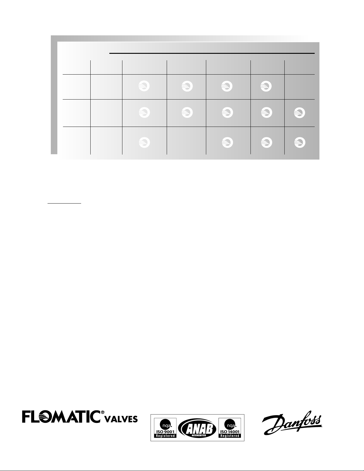
SELECTION GUIDE
APPLICATION
Type of Model Back Back Continuous Low High
Device Siphonage Pressure Pressure Hazard Hazard
Double
Check DCVE
Valve
Reduced RPZE &
Pressure RPZE II
Principle
Pressure
Type PVB
Vacuum
Breaker
DEFINITION: Back Siphonage -A form of backflow due to a reduction in system pressure
resulting in a negative or sub-atmospheric pressure
at a site in the water system.
Back-Pressure -Any increase of pressure in the downstream piping system
above the supply pressure which would cause or tend to cause a
reversal of the normal direction of flow.
Continuous Pressure -Extended or prolonged pressure.
Low Hazard -An actual or potential threat to the physical properties of the
water system or the portability of consumer's water system,
but which would not constitute a health or system hazard.
High Hazard -An actual or potential threat of contamination of a physical or
toxic nature to the consumer's water system that would be a
danger to health.
15 Pryun’s Island Drive
Glens Falls, N.Y. 12801-4424
800-833-2040 • 518-761-9797 • Fax 518-761-9798
www.flomatic.com
e-mail: [email protected]
OMBF-REV - /0
5 7 7
 Loading...