

Page 1
Direct Acting Pressure Reducing Valve Specification Sheet
Model C150E
FEATURES:
Sizes: □½” □¾” □1” □1¼”
Maximum pressure 400psi
Maximum water temperature 180ºF
Reduced pressure ranges 15psi to 75psi
15psi to 150psi
Factory preset 50psi
Standard thread connections (FNPT) ANSI B 1.20.1
APPLICATION:
Designed for installation on potable water lines to
reduce high inlet pressure to a lower outlet pressure.
The integral strainer screen makes this device most
suitable for residential and commercial water systems
that require frequent cleaning of sediment and debris.
The direct acting integral by-pass design prevents
buildup of excessive system pressure caused by
thermal expansion. The balance piston design enables
the regulator to react in a smooth and responsive
manner to changes in system flow demand, while at the
same time, providing protection from inlet pressure
changes.
STANDARDS COMPLIANCE:
● ASSE® Listed 1003
● IAPMO
● CSA
®
Listed
®
Listed ½” thru 1”
● City of Los Angeles Approved
● LEAD PLUMBING LAW COMPLIANCE
.25% Max Weighted Average Lead Content
Certified by IAPMO R&T Lab
● Manufactured in compliance with
NSF/ANSI 61-2010
Certified by IAPMO R&T Lab
MATERIALS:
Body
Cover UV Resistant Polymer Composite
Cartridge Delrin™, NSF Listed
Internals Stainless Steel 300 Series
Stem Stainless Steel 300 Series
Elastomers EPDM (FDA approved)
Strainer screen Stainless Steel, 300 Series
Spring Steel
C
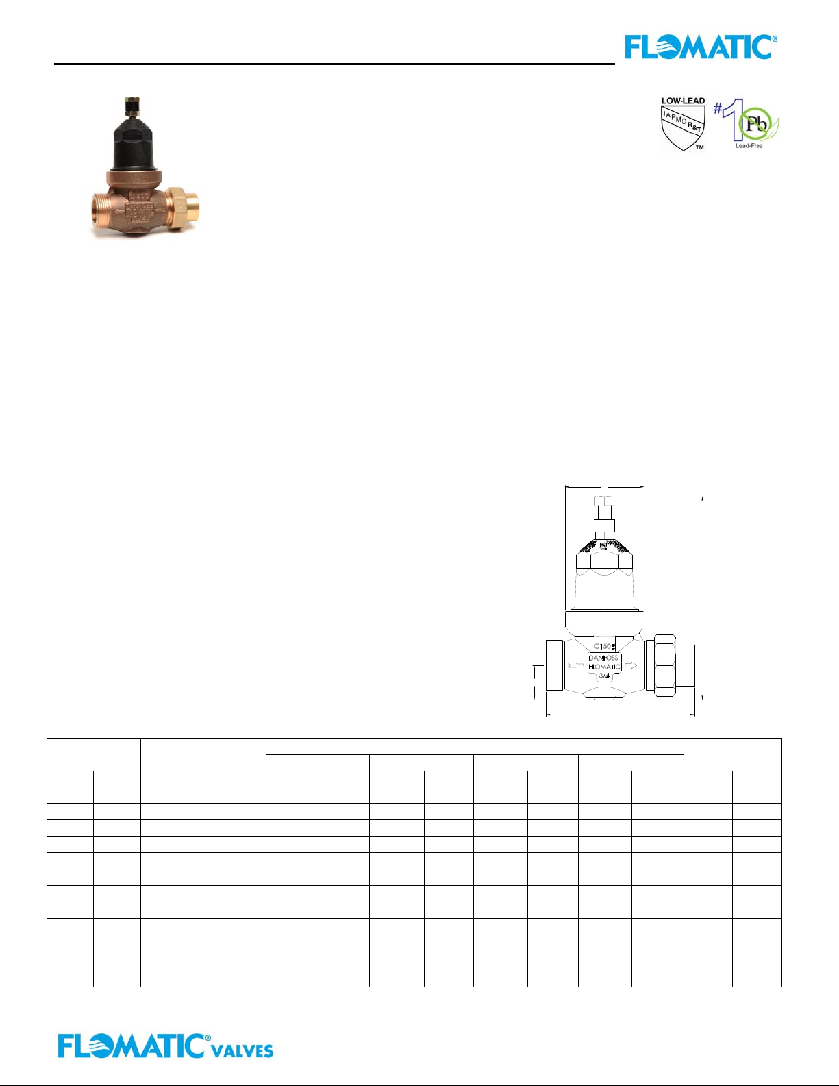
DIMENSIONS
SIZE CONNECTIONS A B C D WEIGHT
in mm in mm in mm in mm in mm lbs kg
½ 15 Single Union 4-3/8 111 6-1/8 156 1-1/32 26 2-3/8 60 3 1.5
½ 15 Less Union 3-1/2 89 6-1/8 156 1-1/32 26 2-3/8 60 3 1.5
½ 15 Double Union 5-1/4 133 6-1/8 156 1-1/32 26 2-3/8 60 3 1.5
¾ 20 Single Union
4-7/16
113 6-1/8 156 1-1/32 26 2-3/8 60 3 1.5
¾ 20 Less Union 3-1/2 89 6-1/8 156 1-1/32 26 2-3/8 60 3 1.5
¾ 20 Double Union 5-3/8 137 6-1/8 156 1-1/32 26 2-3/8 60 3 1.5
1 25 Single Union
4-15/16
125 7-5/8 194 1-1/8 29 3 76 4 2.0
1 25 Less Union 4 102 7-5/8 194 1-1/8 29 3 76 4 2.0
1 25 Double Union 5-7/8 150 7-5/8 194 1-1/8 29 3 76 4 2.0
1-¼”
1-¼”
1-¼”
* Consult factory for copper sweat and barbed end connections
32 Single Union
32 Less Union 5 125 8-3/8 213 1-9/16 40 3 76 5.3 2.4
32 Double Union 7-3/8 187 8-3/8 213 1-9/16 40 3 76 5.3 2.4
6-3/16
Flomatic Corporation, 15 Pruyn’s Island, Glens Falls, New York 12801
Phone: 518-761-9797 Fax: 518-761-9798 www.flomatic.com
157 8-3/8 213 1-9/16 40 3 76 5.3 2.4
Flomatic Corporation
Bronze C89833
Buna Nitrile (FDA approved)
D
B
A
May 3,2004 Rev. H (7/13)
Specification Sheet C150E-2
Page 2
Direct Acting Pressure Reducing Valve Specification Sheet
Model C150E
P
k
138 14
S
S
O
L
E
R
U
S
35 53.5
S
E
R
P
C
i
a
s
W
/
p
M
20
1510.5103
1069 7
0
1.1452.27
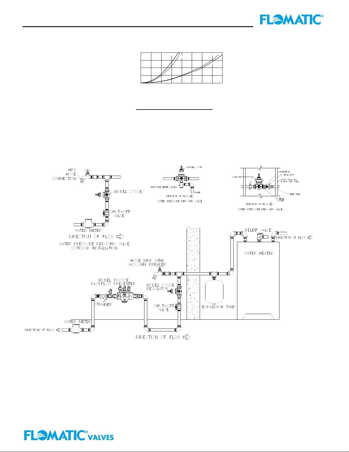
FLOW CURVES
1/2" (15mm)
10 15
3.41
.95.63.32
3/4" (20mm)
FLOW RATE
5.684.54 6.81
1.891.581.26
1" (25mm)
1-1/4" (32 mm)
7.95
2.21
40 gpm35302520
9.08 M /H
2.52 lps
3
TYPICAL INSTALLATION:
FAILURE TO FOLLOW THESE INSTRUCTION WILL VOID ANY WARRANTY
Local codes shall govern installation requirements. Unless otherwise specified, the assembly shall be mounted in
accordance with the latest edition of the Uniform Plumbing Code. The Model C150E may be installed in any position.
The assembly shall be installed with sufficient side clearance for testing and maintenance. Multiple installations are
recommended for wide demand variations or where the desired pressure reduction is more than 4 to 1 (i.e. 200 psi inlet
reduced to 50 psi outlet). CAUTION: Anytime a reducing valve is adjusted, a pressure gauge must be used
downstream to verify correct pressure setting. Do not bottom out adjusting screw on cover.
SPECIFICATIONS:
The Water Pressure Reducing Valve shall be ASSE
®
Listed 1003, and available with single union, double union and less
union end connections. The main body shall be Bronze C89833. The cover shall be composite plastic. The cartridge
shall be Delrin and incorporate an integral seat. The disc elastomer shall be EPDM. The assembly shall be
accessible for maintenance without removing the device from the line. The pressure reducing valve shall be a Flomatic
Model C150E
WARRANTY: Flomatic valves are guaranteed against defects of materials or workmanship when used for the services
recommended. If in any recommended service, a defect develops due to material or workmanship, and the device is returned, freight
prepaid, to Flomatic Corporation within 12 months from the date of purchase, it will be repaired or replaced free of charge. Flomatic
Corporations’ liability shall be limited to our agreement to repair or replace the valve only.
Flomatic Corporation, 15 Pruyn’s Island, Glens Falls, New York 12801
Phone: 518-761-9797 Fax: 518-761-9798 www.flomatic.com
Flomatic Corporation
May 3,2004 Rev. H (7/13)
Specification Sheet C150E-2
Page 3

Pressure Reducing Valve Specification Sheet
Model C150E
FEATURES:
Sizes: □1-½” □2”
Maximum pressure 400psi
Maximum water temperature 180ºF
Reduced pressure ranges 15psi to 75psi
15psi to 150psi
Factory preset 50psi
Standard thread connections (FNPT) ANSI B 1.20.1
APPLICATION:
Designed for installation on potable water lines to
reduce high inlet pressure to a lower outlet pressure.
The integral strainer screen makes this device most
suitable for residential and commercial water systems
that require frequent cleaning of sediment and debris.
The direct acting integral by-pass design prevents
buildup of excessive system pressure caused by
thermal expansion. The balance piston design enables
the regulator to react in a smooth and responsive
manner to changes in system flow demand, while at the
same time, providing protection from inlet pressure
changes.
STANDARDS COMPLIANCE:
● ASSE
● IAPMO
®
Listed 1003
®
Listed
● City of Los Angeles Approved
● LEAD PLUMBING LAW COMPLIANCE
.25% Max Weighted Average Lead Content
Certified by IAPMO R&T Lab
MATERIALS:
Body & Cover Bronze C89833
Cartridge Delrin™, NSF Listed
Internals Stainless Steel 300 Series
Stem Stainless Steel 300 Series
Elastomers EPDM (FDA approved)
Strainer screen Stainless Steel, 300 Series
Spring Steel
DIMESIONS
SIZE CONNECTIONS A B C D WEIGHT
in mm in mm in mm in mm in mm lbs kg
1-1/2 40 Single Union 7-5/64 180 9-15/16 252 2-3/16 56 5-3/16 132 14.5 6.6
1-1/2 40 Less Union 5-13/16 148 9-15/16 252 2-3/16 56 5-3/16 132 13.5 6.2
1-1/2 40 Double Union 8-11/32 212 9-15/16 252 2-3/16 56 5-3/16 132 15.5 7
2 50 Single Union 7-5/64 180 9-15/16 252 2-3/16 56 5-3/16 132 15.3 6.9
2 50 Less Union 5-13/16 148 9-15/16 252 2-3/16 56 5-3/16 132 14.3 6.5
2 50 Double Union 8-11/32 212 9-15/16 252 2-3/16 56 5-3/16 132 16.3 7.4
Flomatic Corporation
Buna Nitrile (FDA approved)
Flomatic Corporation, 15 Pruyn’s Island, Glens Falls, New York 12801
Phone: 518-761-9797 Fax: 518-761-9798 www.flomatic.com
April 29,2004 Rev. D (6/11)
Specification Sheet C150
Page 4

Pressure Reducing Valve Specification Sheet
Models C150E
S
a
S
P
k
O
L
E
R
U
S
M
138 2014
103 10.5 15
69 107
S
E
R
P
C
i
s
W
/
p
3.5 535
0
20 40
1.26 3.792.52
FLOW CURVES
9.08
60
13.64.54
1-1/2" (40mm)
80
18.17
5.04
2" (50mm)
100
22.71
6.31
TYPICAL INSTALLATION:
FAILURE TO FOLLOW THESE INSTRUCTION WILL VOID ANY WARRANTY
Local codes shall govern installation requirements. Unless otherwise specified, the assembly shall be mounted in
accordance with manufacture’s instructions and the latest edition of the Uniform Plumbing Code. The Model C150E
may be installed in any position. The assembly shall be installed with sufficient side clearance for testing and
maintenance. Multiple installations are recommended for wide demand variations or where the desired pressure
reduction is more than 4 to 1 (i.e. 200 psi inlet reduced to 50 psi outlet). CAUTION: Anytime a reducing valve is
adjusted, a pressure gauge must be used downstream to verify correct pressure setting. Do not bottom out adjusting
bolt on bell housing.
SPECIFICATIONS:
The Water Pressure Reducing Valve shall be ASSE
union end connections. The main body shall be Bronze C89833. The cover shall be composite plastic. The cartridge
shall be Delrin and incorporate an integral seat. The disc elastomer shall be EPDM. The assembly shall be
accessible for maintenance without removing the device from the line. The pressure reducing valve shall be a Flomatic
Model C150E
WARRANTY: Flomatic valves are guaranteed against defects of materials or workmanship when used for the services
recommended. If in any recommended service, a defect develops due to material or workmanship, and the device is
returned, freight prepaid, to Flomatic Corporation within 12 months from the date of purchase, it will be repaired or
replaced free of charge. Flomatic Corporations’ liability shall be limited to our agreement to repair or replace the valve
only.
FLOW RATE
®
Listed 1003, and available with single union, double union and less
Flomatic Corporation
120 gpm
3
27.25 M /H
7.56 lps
Flomatic Corporation, 15 Pruyn’s Island, Glens Falls, New York 12801
Phone: 518-761-9797 Fax: 518-761-9798 www.flomatic.com
April 29,2004 Rev. D (6/11)
Specification Sheet C150
 Loading...